TW/.., PCW/.., XW/R/IQ Wireless Sensors and Receiver Data ... - Trend
TW/.., PCW/.., XW/R/IQ Wireless Sensors and Receiver Data ... - Trend
TW/.., PCW/.., XW/R/IQ Wireless Sensors and Receiver Data ... - Trend
Create successful ePaper yourself
Turn your PDF publications into a flip-book with our unique Google optimized e-Paper software.
<strong>Data</strong> Sheet<br />
<strong>TW</strong>/.., <strong>PCW</strong>/.., <strong>XW</strong>/R/<strong>IQ</strong><br />
<strong>Wireless</strong> <strong>Sensors</strong> <strong>and</strong> <strong>Receiver</strong><br />
<strong>TW</strong>/.., <strong>PCW</strong>/.., <strong>XW</strong>/R/<strong>IQ</strong> <strong>Wireless</strong> <strong>Sensors</strong><br />
<strong>and</strong> <strong>Receiver</strong><br />
Description<br />
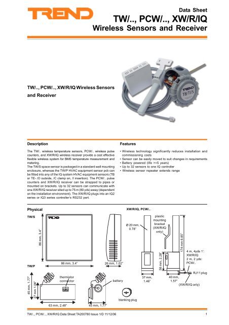
The <strong>TW</strong>/.. wireless temperature sensors, <strong>PCW</strong>/.. wireless pulse<br />
counters, <strong>and</strong> <strong>XW</strong>/R/<strong>IQ</strong> wireless receiver provide a cost effective<br />
flexible wireless system for BMS temperature measurement <strong>and</strong><br />
metering.<br />
The <strong>TW</strong>/S space sensor is packaged in a st<strong>and</strong>ard wall mounting<br />
enclosure, whereas the <strong>TW</strong>/P HVAC equipment sensor pcb can<br />
be fitted into any of the <strong>IQ</strong> system HVAC equipment sensors (TB<br />
or TE- /O outside, /C clamp on, /I insertion). The <strong>PCW</strong>/.. pulse<br />
counters <strong>and</strong> <strong>XW</strong>/R/<strong>IQ</strong> receiver can be strapped to pipes or<br />
mounted on brackets. Up to 32 sensors can communicate with<br />
one <strong>XW</strong>/R/<strong>IQ</strong> receiver sited up to 75 m (80 yds) away (dependent<br />
on the installation environment). The <strong>XW</strong>/R/<strong>IQ</strong> plugs into an <strong>IQ</strong>2<br />
series or <strong>IQ</strong>3 series controller’s RS232 port.<br />
Features<br />
• <strong>Wireless</strong> technology significantly reduces installation <strong>and</strong><br />
commissioning costs<br />
• Sensor can be easily moved to suit changes in requirements<br />
• Battery powered (life >=5 years)<br />
• Up to 32 sensors to one <strong>IQ</strong> controller<br />
• <strong>Wireless</strong> sensor repeater extends range<br />
Physical<br />
<strong>XW</strong>/R/<strong>IQ</strong>, <strong>PCW</strong>/..<br />
<strong>TW</strong>/S<br />
<strong>TW</strong>/P<br />
45 mm, 1.77”<br />
27 mm 1.06”<br />
86 mm, 3.4”<br />
86 mm, 3.4” 26 mm, 1.02”<br />
thermistor<br />
connector<br />
battery<br />
Ø 20 mm,<br />
0.78”<br />
blanking plug<br />
37 mm,<br />
1.46”<br />
plastic<br />
mounting<br />
bracket<br />
(<strong>XW</strong>/R/<strong>IQ</strong><br />
only)<br />
58 mm, 2.28”<br />
174 mm 6.85”<br />
4 m, 4yds 1’:<br />
<strong>XW</strong>/R/<strong>IQ</strong><br />
2 m, 2 yds:<br />
<strong>PCW</strong>/..<br />
RJ11 plug<br />
40 mm,<br />
1.57”<br />
(<strong>XW</strong>/R/<strong>IQ</strong> only)<br />
63 mm, 2.48”<br />
45 mm, 1.77”<br />
<strong>TW</strong>/.., <strong>PCW</strong>/.., <strong>XW</strong>/R/<strong>IQ</strong> <strong>Data</strong> Sheet TA200780 Issue 1/D 11/12/06<br />
1
100-240 V<br />
OK<br />
RX<br />
<strong>TW</strong>/.., <strong>PCW</strong>/.., <strong>XW</strong>/R/<strong>IQ</strong><br />
<strong>Data</strong> Sheet<br />
Physical (continued)<br />
ACCW/CONFIGKIT cable<br />
(kit also includes CD containing configuration software)<br />
ACCW/FK/SS<br />
3 m, 3 yds 1’<br />
9 Way D type<br />
Female (PC)<br />
2 screw terminals<br />
(<strong>IQ</strong> 24 V AUX output<br />
supply)<br />
stainless steel bracket<br />
(accessory for <strong>XW</strong>/R/<strong>IQ</strong>, <strong>PCW</strong>/..)<br />
3 m, 3 yds 1’<br />
RJ11 socket (<strong>XW</strong>/R/<strong>IQ</strong>)<br />
ACCW/RW/<strong>IQ</strong> (wireless sensor repeater)<br />
antenna<br />
13 A plug<br />
(supplied)<br />
230 Vac<br />
supply<br />
6 mm, 0.24”<br />
80 mm, 3.15”<br />
315 mm, 12.4”<br />
158 mm, 6.22”<br />
2 holes Ø 9 mm<br />
190 mm, 7.48”<br />
2 m, 2 yds<br />
180 mm, 7.09”<br />
60 mm, 2.36”<br />
FUNCTIONALITY<br />
The <strong>TW</strong>/.., <strong>PCW</strong>/.., <strong>XW</strong>/R/<strong>IQ</strong> wireless system consists of up to 32 wireless sensors (consisting of a mix of <strong>TW</strong>/.. <strong>and</strong> <strong>PCW</strong>/..)<br />
transmitting to an <strong>XW</strong>/R/<strong>IQ</strong> receiver. The <strong>XW</strong>/R/<strong>IQ</strong> receiver plugs into the local supervisor port of an <strong>IQ</strong>2 or <strong>IQ</strong>3 controller, <strong>and</strong> writes<br />
the sensors’ values <strong>and</strong> their status to defined analogue nodes <strong>and</strong> digital points within the <strong>IQ</strong> controller.<br />
Each wireless sensor is identified by a unique 3 byte (16,777,216 variants) number, which is printed on the sensor’s identification<br />
label. Using the ACCW/CONFIGKIT configuration software, the <strong>XW</strong>/R/<strong>IQ</strong> should be programmed to allocate each identification number<br />
to an analogue node within the local <strong>IQ</strong>, or within another <strong>IQ</strong> on the local Lan. The selected analogue node has associated digital<br />
points for reception of the sensor’s status<br />
<strong>PCW</strong>/..<br />
<strong>TW</strong>/S<br />
<strong>TW</strong>/P<br />
(installed in TB/TI)<br />
<strong>TW</strong>/P<br />
(installed in TB/TO)<br />
<strong>XW</strong>/R/<strong>IQ</strong><br />
up to 32 sensors<br />
RJ11<br />
<strong>Wireless</strong> <strong>Sensors</strong><br />
<strong>Wireless</strong> sensors measure the required parameters <strong>and</strong> transmit<br />
them regularly to the <strong>XW</strong>/R/<strong>IQ</strong> receiver.<br />
The sensor is powered by a lithium battery. If a low battery<br />
condition occurs, it will be indicated in the sensor’s digital status<br />
bits. The batteries are not field replaceable, <strong>and</strong> when the battery<br />
has run down (voltage
<strong>Data</strong> Sheet<br />
<strong>TW</strong>/.., <strong>PCW</strong>/.., <strong>XW</strong>/R/<strong>IQ</strong><br />
FUNCTIONALITY (continued)<br />
<strong>TW</strong>/P, HVAC Equipment Sensor PCB<br />
The <strong>TW</strong>/P is a thermistor temperature sensor suitable for a field<br />
fitting to a TE/T.. or TB/T.. HVAC Equipment sensor.<br />
i.e. TB/TO, TE/TO outside temperature sensor<br />
TB/TC, TE/TC<br />
TB/TI/S, /L<br />
TE/TE<br />
TE/TD/S, /L<br />
clamp on temperature sensor<br />
short <strong>and</strong> long insertion temperature<br />
sensor (for use as either immersion or<br />
duct sensor)<br />
immersion temperature sensor<br />
short <strong>and</strong> long duct temperature sensor<br />
Field Fitting: The <strong>TW</strong>/P is fitted into a TE/T.. or TB/T..<br />
HVAC Equipment sensor by:<br />
1. Removing lid from HVAC Equipment sensor<br />
2. Disconnecting wires from terminal block<br />
3. Discarding terminal block<br />
4. Removing <strong>and</strong> discarding M20 gl<strong>and</strong>, (but<br />
retaining nut)<br />
5. Screwing blanking plug into retaining nut<br />
6. Connecting the sensor wires to <strong>TW</strong>/P pcb<br />
7. Inserting pcb into housing (see below)<br />
8. Noting sensor’s 8 digit identifier (<strong>and</strong> removing<br />
the second identifier label if required)<br />
9. Closing lid<br />
blanking plug<br />
<strong>TW</strong>/P pcb<br />
<strong>TW</strong>/P pcb mounted in HVAC equipment sensor housing<br />
<strong>PCW</strong>/.. Pulse Counters, <strong>XW</strong>/R/<strong>IQ</strong> <strong>Receiver</strong><br />
The unit may be mounted using an optional stainless steel bracket<br />
(ACCW/FK/SS), or using the plastic bracket supplied with the<br />
<strong>XW</strong>/R/<strong>IQ</strong> only, or alternatively it can be tied to a pipe or other<br />
structure using a plastic cable tie.<br />
plastic cable<br />
tie<br />
<strong>XW</strong>/R/<strong>IQ</strong> receiver: The <strong>XW</strong>/R/<strong>IQ</strong> receiver is supplied with a 4 m<br />
(4 yds 1’) screened cable for connecting to an <strong>IQ</strong> controller. If<br />
a longer distance is required (up to 15 m, 16 yds), then an RJ11<br />
extension cable may be used. The receiver is powered from the<br />
controller.<br />
Optimum range will only be achieved if the antenna is kept clear<br />
of metallic objects such as water tanks <strong>and</strong> other conducting<br />
surfaces.<br />
Transmission<br />
The transmitters will transmit in a short burst approximately as<br />
follows:<br />
<strong>TW</strong>/S: every 2 minutes<br />
<strong>TW</strong>/P: every 1½ minutes<br />
<strong>PCW</strong>/METER: every 1 minute<br />
<strong>PCW</strong>/STATUS: every 4 minutes, <strong>and</strong> on change of input<br />
state with a triple burst (with 1s separation).<br />
In between transmissions they will switch into low power ‘sleep’<br />
mode.<br />
The transmission consists of the sensor identifier, the value, <strong>and</strong><br />
the sensor’s status.<br />
Each <strong>XW</strong>/R/<strong>IQ</strong> receiver must be programmed with a 32 entry<br />
internal look-up table of its associated sensors.<br />
Transmitter Analogue Node<br />
O/S Address<br />
Address<br />
No.<br />
Entry<br />
00698624<br />
A201<br />
8<br />
Each entry in the table associates a sensor with the <strong>XW</strong>/R/<strong>IQ</strong><br />
receiver <strong>and</strong> references the sensor’s 8 digit identifier to both its<br />
target analogue node, <strong>and</strong> its target outstation.<br />
Note that the nodes used will have to be created in the strategy<br />
for <strong>IQ</strong>3 controllers (they always exist in <strong>IQ</strong>2xx controllers).<br />
Normally the outstation number will be the device address of the<br />
outstation to which it is connected, but it may be the address of<br />
another outstation on its local Lan. If it uses another outstation<br />
then the local outstation’s proxy CNC must be set up (i.e. the local<br />
supervisor port address must be non-zero).<br />
The sensor sends its status bits to the receiver: all sensors send<br />
battery fail status, <strong>TW</strong>/.. sensors send the sensor fail status, <strong>and</strong><br />
the <strong>PCW</strong>/STATUS sends the input state. The receiver will also<br />
detect if the sensor is failing to update within 15 mins, <strong>and</strong><br />
generate a loss of reception status. The receiver produces the<br />
sensor status bits.<br />
R O L H<br />
bit 7 6 5 4 3 2 1 0<br />
0 0 0 0 0 1 1 0<br />
plastic bracket supplied<br />
(<strong>XW</strong>/R/<strong>IQ</strong> only)<br />
horizontal pipe<br />
vertical<br />
pipe<br />
loss of reception<br />
sensor failure (<strong>TW</strong>/..)<br />
low battery<br />
input state (<strong>PCW</strong>/STATUS)<br />
<strong>PCW</strong>/.. Pulse Counters: Whenever monitoring hot water<br />
systems it is not advisable to mount the pulse counter directly<br />
on the pipe without intervening insulation. A <strong>PCW</strong>/.. pulse counter<br />
is supplied with a 2 metre (2 yds) screened cable for connecting<br />
to the input contact.<br />
The input may be provided by a volt free contact, opto-coupler,<br />
or transistor switch.<br />
The <strong>PCW</strong>/.. pulse counters (/METER <strong>and</strong> /STATUS) will count the<br />
number of pulses received <strong>and</strong> transmit the accumulated value<br />
to the receiver. The count will roll round back to zero at 16777215.<br />
The <strong>PCW</strong>/METER sends the value every minute <strong>and</strong> is compatible<br />
with receivers of serial number 2404701 <strong>and</strong> greater.<br />
The <strong>PCW</strong>/STATUS also sets one of its status bits to the state of<br />
the input. It is designed to monitor non-fleeting inputs; the state<br />
must last longer than 5s. It sends the value <strong>and</strong> status on change<br />
of input state <strong>and</strong> every 4 minutes. The <strong>PCW</strong>/STATUS is compatible<br />
with receivers of serial number 2505157 <strong>and</strong> greater.<br />
On receipt of a value from the controller the receiver will send<br />
the sensor value to the analogue node <strong>and</strong> outstation address<br />
set up in appropriate entry in the look-up table, <strong>and</strong> it will send<br />
the status bits to the alarm byte associated with that node in <strong>IQ</strong>2<br />
<strong>and</strong> <strong>IQ</strong>1 series controllers (e.g. A200 uses byte 240 by convention<br />
- see <strong>IQ</strong> Digital/Analogue Array Reference Card, TB100522)<br />
For <strong>IQ</strong>3 controllers the analogue node has to be created when<br />
engineering the strategy. The four status outputs, Read (R),<br />
Outside Limits (O), Low (L), High (H) corresponding to the status<br />
bits (3 to 0 respectively) are provided in the analogue node<br />
module (see compatibility section).<br />
The status bits are sent to the local controller using text comms<br />
(if transmitting to another controller, IC Comms wil be used).<br />
<strong>TW</strong>/.., <strong>PCW</strong>/.., <strong>XW</strong>/R/<strong>IQ</strong> <strong>Data</strong> Sheet TA200780 Issue 1/D 11/12/06<br />
3
100-240 V<br />
OK<br />
RX<br />
<strong>TW</strong>/.., <strong>PCW</strong>/.., <strong>XW</strong>/R/<strong>IQ</strong><br />
<strong>Data</strong> Sheet<br />
FUNCTIONALITY (continued)<br />
Reception<br />
The recommended maximum range between a wireless sensor<br />
<strong>and</strong> the <strong>XW</strong>/R/<strong>IQ</strong> receiver is 75 metres (80 yds).<br />
All sensors transmit on the same frequency b<strong>and</strong> (433.05 to<br />
434.79 MHz).<br />
Propagation<br />
The signal propagation within the building also depends on :<br />
Reflection from flat surfaces such as metal cladding,<br />
galvanized roofing, foil backed plaster board.<br />
Radiation from thin conductors such a pipe work, electrical<br />
wiring, steel.<br />
Reflection <strong>and</strong> re-transmission can result in a st<strong>and</strong>ing<br />
wave being set up in the area. If the receiver happens<br />
to be in a null of the wave, moving its position slightly will<br />
result in stronger reception.<br />
Absorption by lossy materials such as damp concrete,<br />
stone work, <strong>and</strong> people. High RF barriers are paper (e.g.<br />
books), concrete (floors, outer walls), <strong>and</strong> metal<br />
(elevator shafts, cabinets).<br />
Generally, the higher the transmitter is mounted, the further the<br />
signal will reach. It is recommended to mount the transmitter<br />
above partition height if possible.<br />
Interference<br />
It is not recommended that other equipment operating over the<br />
same frequency b<strong>and</strong> be used in the same environment (e.g.<br />
amateur radio). It is also advisable to keep the wireless sensors<br />
<strong>and</strong> <strong>XW</strong>/R/<strong>IQ</strong> away from other sources of interference e.g.<br />
computer (>1 m, 1 yds), microwave ovens, switch mode power<br />
supplies.<br />
ACC/RW/<strong>IQ</strong> Repeater<br />
The repeater can be used to increase the maximum distance<br />
between a transmitter <strong>and</strong> the receiver. Thus, if the repeater is<br />
placed within 75 metres (80 yds) of the transmitter, the receiver<br />
can then be 75 metres (80 yds) from the repeater which increases<br />
the total distance from the transmitter to the receiver to 150 metres<br />
(160 yds).<br />
In a white walled building (a building with rooms thermally insulated<br />
with foam <strong>and</strong> aluminium sheets; food industry) best performance<br />
may be found by mounting the repeater in the loft space above<br />
the white walled area. There will always be a degree of leakage<br />
in a white walled building, <strong>and</strong> propagation is much easier out<br />
of the room, in a loft space, compared to between white walls.<br />
Enclosure: The repeater is supplied in a compact diecast<br />
wall mounting enclosure.The bracket supplied should be<br />
used to secure the unit to a wall such that the antenna<br />
is vertically polarised.<br />
Input Power: The repeater requires 230 Vac 50 Hz at<br />
<strong>Data</strong> Sheet<br />
<strong>TW</strong>/.., <strong>PCW</strong>/.., <strong>XW</strong>/R/<strong>IQ</strong><br />
FUNCTIONALITY (continued)<br />
The configuration software will be installed in Program files/Project1 by default. It will appear in the Start/Programs menu as Rtcom-<br />
<strong>Trend</strong>/Rtcom-<strong>Trend</strong>. Once the program is started it will display the following page.<br />
PIN number in use (if any)<br />
look-up table<br />
communications<br />
window<br />
The configuration software enables the look-up table stored in<br />
the <strong>XW</strong>/R/<strong>IQ</strong> to be configured. There are 32 rows in the table, one<br />
for each sensor entry. Each row in the table has the following<br />
parameters.<br />
1. Transmitter Address: An 8 digit identification number,<br />
unique to each transmitter (e.g. 00016932 will be<br />
displayed as 16932). The identification number is shown<br />
on a label attached to the wireless sensor.<br />
2. Analogue Node Number: This is the node within the <strong>IQ</strong><br />
controller to which the sensor’s value will be written. It<br />
must be configured.<br />
3. Outstation Address: This is the controller address on the<br />
local Lan. It is normally the address of the local controller,<br />
but it can be the address of another controller on the local<br />
Lan. A value of zero is invalid <strong>and</strong> will cause that sensor<br />
entry to be delivered.<br />
Note that the sensor value is then sent to the address, analogue<br />
node xx in <strong>IQ</strong>yy (xx is an analogue node number, yy is a O/S<br />
address).<br />
If the value is to be sent to another controller then the local<br />
controller’s local supervisor port address must be set greater<br />
than zero.<br />
4. Current value: The last value received from the sensor;<br />
the value is transmitted every 2 minutes (for <strong>TW</strong>/S),<br />
every 1 minute (for <strong>TW</strong>/P, <strong>PCW</strong>/METER), <strong>and</strong> every 4<br />
minutes (for <strong>PCW</strong>/STATUS; plus on every input change).<br />
Note that for <strong>PCW</strong>/METER or <strong>PCW</strong>/STATUS the initial<br />
value should be recorded as it will vary from unit to unit.<br />
The pulse counter has been designed not to have reset<br />
capability in order to prevent fraud.<br />
The full configuration details are covered by the <strong>XW</strong>/R/<strong>IQ</strong><br />
Configuration Software Manual, but the sequence given below<br />
covers the main steps:<br />
1. The <strong>XW</strong>/R/<strong>IQ</strong> receiver <strong>and</strong> its wireless sensors should<br />
be installed according to their installation instructions.<br />
2 On the ‘Protocol’ menu ensure that the ‘<strong>Trend</strong> Protocol’<br />
option is selected (✔).<br />
3. On the ‘Port’ menu select the port number of the RS232<br />
port to which the <strong>XW</strong>/R/<strong>IQ</strong> is connected; the selected<br />
port number will then be indicated by a tick (✔).<br />
4. If the controller has a password set up, specify a PIN in<br />
the <strong>XW</strong>/R/<strong>IQ</strong> that matches one of priority level 95 or<br />
greater set in the controller. On the ‘Configuration’ menu<br />
select ‘Program PIN Number’ <strong>and</strong> enter the PIN.<br />
If the controller does not have a password set up, then<br />
on the ‘Configuration’ menu select ‘disable PIN code’.<br />
Note that if the sensor values are to be sent to several controllers<br />
then all these controllers must have the same password setup<br />
(>=level 90).<br />
5. To check the existing configuration table within the <strong>XW</strong>/R/<br />
<strong>IQ</strong>, on the ‘Configuration’ menu select ‘Read Channels 1-<br />
16’; this will display the information in the first 16 entries<br />
in the table. Then ‘Read Channels 17-32’ to read the<br />
information in the last 16 entries.<br />
6. The configuration menu may be amended or cleared <strong>and</strong><br />
set up from scratch.<br />
The available sensors can be found from the<br />
communications window; on the ‘Configuration’ menu<br />
select Output Mode <strong>and</strong> ‘0 - All transmitters [binary]’. This<br />
will change the communication display into a more legible<br />
format. It will show the communications from all the<br />
sensors that the <strong>XW</strong>/R/<strong>IQ</strong> can receive.<br />
5. Received Time: The time the last value was received<br />
from the sensor.<br />
<strong>TW</strong>/.., <strong>PCW</strong>/.., <strong>XW</strong>/R/<strong>IQ</strong> <strong>Data</strong> Sheet TA200780 Issue 1/D 11/12/06<br />
5
<strong>TW</strong>/.., <strong>PCW</strong>/.., <strong>XW</strong>/R/<strong>IQ</strong><br />
<strong>Data</strong> Sheet<br />
FUNCTIONALITY (continued)<br />
Each communication shows the Address (identification number)<br />
of the sensor <strong>and</strong> its current value:<br />
Multiple <strong>Sensors</strong> <strong>and</strong> <strong>Receiver</strong>s<br />
<strong>XW</strong>/R/<strong>IQ</strong> receivers will receive communications from all wireless<br />
sensors within range (nominally 75 metres, 80 yds, but this can<br />
be affected by the installed environment <strong>and</strong> by the use of<br />
repeaters). Thus in the diagram below both <strong>XW</strong>/R/<strong>IQ</strong> receivers<br />
will receive from all wireless sensors 1, 2, <strong>and</strong> 3.<br />
< 75 m, 80 yds radius<br />
1 2<br />
<strong>TW</strong><br />
<strong>TW</strong><br />
A<br />
3 B<br />
<strong>XW</strong><br />
<strong>PCW</strong><br />
<strong>XW</strong><br />
Communications window when set to:<br />
‘0 - All transmitted (binary)’<br />
Thermistor Temperature TX.: 16940 Temperature: 27.7 ADC: 376<br />
f/w V4<br />
$8A $0 $42 $2C $1 $1 $15 $1 $78 $9 $E9<br />
sensor address<br />
Choose a sensor address from the available sensors<br />
stored in the communications window <strong>and</strong> type its details<br />
into the next available row in the table.<br />
e.g. Transmitter Analogue O/S Current<br />
Address Node No. Address Value<br />
16940 204 21<br />
Once the address is entered, moving the cursor to the<br />
‘Analogue Node No.’ will cause the number to change to<br />
the next node in sequence (i.e. increment the node<br />
number from the node above). Moving the cursor to the<br />
O/S address will cause it to default to the same O/S<br />
address as the row above.<br />
The value received from the sensor will then be entered<br />
into the current value position.<br />
The system configuration engineer can decide how the <strong>XW</strong>/R/<strong>IQ</strong><br />
receivers can be configured to select which wireless sensors<br />
each of them receives.<br />
If the engineer wishes, a wireless sensor can be received by<br />
more than 1 receiver; this will enable the same value to be<br />
present in 2 controllers, hence a degree of redundancy can be<br />
provided. Alternatively the value may be sent from controller to<br />
controller by IC comms.<br />
COMPATIBILITY<br />
Controllers: The <strong>XW</strong>/R/<strong>IQ</strong> is compatible with <strong>IQ</strong>2xx controllers<br />
<strong>and</strong> all <strong>IQ</strong>3’s. The st<strong>and</strong>ard <strong>XW</strong>/R/<strong>IQ</strong> relies on the <strong>IQ</strong> controller to<br />
supply its power from the RS232 local supervisor RJ11 socket.<br />
This is available on all current <strong>IQ</strong>2s <strong>and</strong> <strong>IQ</strong>3s except for the <strong>IQ</strong>251.<br />
Connection to an <strong>IQ</strong>251 (or any other <strong>IQ</strong>2 without 24 V output<br />
supply available on its RJ11) requires the use of the additional<br />
adaptor cable RD/SDU-ADAPTOR <strong>IQ</strong>2xx.<br />
7. On the ‘Configuration’ menu select ‘Output Mode’ <strong>and</strong><br />
‘5 - Programmed Transmitters <strong>Trend</strong> Protocol [ASCII]’.<br />
<strong>XW</strong>/R/<strong>IQ</strong><br />
2 terminal<br />
24 V AUX<br />
!<br />
CAUTION<br />
Ensure that the menu item ‘Configuration/Output<br />
mode’ is set back to ‘5 - Programmed Transmitter<br />
<strong>Trend</strong> Protocol (ASCII)’ or the receiver will not<br />
operate.<br />
8. On the ‘Configuration’ menu select ‘Program Channels<br />
1-16’ to write the first 16 items of the configuration table,<br />
<strong>and</strong> then select ‘Program Channels 17-32’ to write the<br />
last 16 entries. This will program the <strong>XW</strong>/R/<strong>IQ</strong> receiver<br />
with the new table.<br />
9. On the ‘Configuration’ menu select ‘Read Channels 1-16’<br />
<strong>and</strong> then select ‘Read Channels 17-32’ to check that the<br />
table is correct.<br />
10. Plug the <strong>XW</strong>/R/<strong>IQ</strong> receiver into its <strong>IQ</strong> controller.<br />
RJ11<br />
RJ11<br />
socket<br />
RD/SDU-ADAPTOR <strong>IQ</strong>2xx<br />
RJ11<br />
<strong>IQ</strong>2xx<br />
local<br />
supervisor<br />
port<br />
Note that if fitting to a controller, the local supervisor port should<br />
not already be in use (i.e. by SDU-<strong>IQ</strong> or SDU-xcite, RD-<strong>IQ</strong>,<br />
<strong>IQ</strong>View/RS232, NDP, or local PC), <strong>and</strong> the ‘sUperv port addr’<br />
should be set to zero (default).<br />
Note that the <strong>XW</strong>/R/<strong>IQ</strong> is not compatible with /ADL, /ATM or<br />
XNC220 controllers as the RS232 port is already in use.<br />
NOTE that the <strong>PCW</strong>/METER pulse counter is only compatible<br />
with <strong>XW</strong>/R/<strong>IQ</strong> receivers of serial number 2404701 <strong>and</strong> greater,<br />
<strong>and</strong> that the <strong>PCW</strong>/STATUS is only compatible with <strong>XW</strong>/R/<br />
<strong>IQ</strong> receivers of serial number 2505157 <strong>and</strong> greater.<br />
6 <strong>TW</strong>/.., <strong>PCW</strong>/.., <strong>XW</strong>/R/<strong>IQ</strong> <strong>Data</strong> Sheet TA200780 Issue 1/D 11/12/06
<strong>Data</strong> Sheet<br />
<strong>TW</strong>/.., <strong>PCW</strong>/.., <strong>XW</strong>/R/<strong>IQ</strong><br />
COMPATIBILITY<br />
When used with <strong>IQ</strong>3 any analogue nodes used have to be created using SET. An example strategy for a wireless sensor input<br />
is given below. The sensor failure status (<strong>TW</strong>/.. only) <strong>and</strong> loss of reception status are passed through the internal sensor module,<br />
but the battery low status <strong>and</strong> the digital input status (<strong>PCW</strong>/STATUS only) are monitored separately by internal digital inputs.<br />
wireless<br />
sensor’s target<br />
analogue node<br />
0<br />
Analogue node from R<br />
A202<br />
V<br />
D<br />
Analogue<br />
Read Alarm<br />
Out. Limits Alarm<br />
Low Alarm<br />
High Alarm<br />
20<br />
<strong>Wireless</strong> Room Space<br />
S24<br />
V<br />
A202D S<br />
INTERNAL<br />
DegC Units<br />
0 High Alarm Limit<br />
0 Low Alarm Limit<br />
0 High Alarm Delay<br />
0 Low Alarm Delay<br />
0 Out.Limits Delay<br />
0 Read Alarm Delay<br />
Disabled Read Alarm<br />
Disabled Out. Limits Alarm<br />
Disabled Low Alarm<br />
Disabled High Alarm<br />
0 Override Enable<br />
0 Override Value<br />
Sensor 24<br />
S24V S P20<br />
PLOT<br />
1 Min Period<br />
1000 Records<br />
loss of reception status<br />
sensor failure status<br />
(<strong>TW</strong>/.. only)<br />
Low Battery<br />
A202L<br />
I1<br />
S<br />
INTERNAL<br />
battery low status<br />
0 Alarm Delay<br />
0 Required State<br />
Enabled State Alarm<br />
Starts<br />
0 Override Enable<br />
0 Override Value<br />
Digital Input 2<br />
A202H<br />
I2<br />
S<br />
INTERNAL<br />
0 Alarm Delay<br />
0 Required State<br />
Disabled State Alarm<br />
Hours Run<br />
Starts<br />
0 Override Enable<br />
0 Override Value<br />
digital input status<br />
(<strong>PCW</strong>/STATUS only)<br />
INSTALLATION<br />
Note that the location of the sensor <strong>and</strong> receiver should be carefully chosen with consideration given to the interference given in<br />
the reception section above. Mount the units as high as possible. The maximum distance for a sensor from its receiver is 75 m (80 yds)<br />
or 150 m (160 yds) with a centrally placed repeater.<br />
<strong>TW</strong>/S<br />
<strong>TW</strong>/P<br />
Choose location<br />
Mount Sensor (using 2 screws - minimum)<br />
Note sensor identification number<br />
Assemble sensor unit<br />
Choose location <strong>and</strong> TB HVAC equipment sensor type<br />
Remove lid from HVAC equipment sensor<br />
Disconnect <strong>and</strong> remove connector<br />
Remove M20 gl<strong>and</strong> <strong>and</strong> fit blanking plug<br />
Connect <strong>TW</strong>/P to thermistor leads<br />
Note sensor identification number<br />
Close lid<br />
Install HVAC equipment sensor according to its installation<br />
instructions<br />
ACCW/RW/<strong>IQ</strong> (repeater)<br />
Choose location (install within 75 m, 80 yds, of sensor <strong>and</strong> 75 m,<br />
80 yds, of receiver)<br />
Mount on wall using bracket (supplied)<br />
Plug in 230 Vac supply <strong>and</strong> switch on power.<br />
Test System<br />
The installation details are covered by the following documents:<br />
<strong>TW</strong>/S Installation Instructions TG200781<br />
<strong>TW</strong>/P Installation Instructions TG200782<br />
<strong>PCW</strong>/... Installation Instructions TG200834<br />
<strong>XW</strong>/R/<strong>IQ</strong> Installation Instructions TG200783<br />
<strong>XW</strong>/R/<strong>IQ</strong> Configuration Tool Manual TE200793<br />
ACCW/RW/<strong>IQ</strong> Installation Instructions TG200852<br />
<strong>PCW</strong>/...<br />
Choose location<br />
Mount using bracket or cable ties<br />
Note sensor identification number<br />
<strong>XW</strong>/R/<strong>IQ</strong><br />
Choose location<br />
Mount receiver using bracket or cable ties<br />
Configure receiver using ACCW/CONFIGKIT<br />
Plug receiver into controller<br />
(In <strong>IQ</strong>3 configure analogue nodes to receive values)<br />
The installation of the TB HVAC equipment sensors are covered<br />
as follows:<br />
TB/TC, /TI, /TO <strong>Data</strong> Sheet TA200724<br />
TB/TO Installation Instructions TG200725<br />
TB/TC Installation Instructions TG200726<br />
TB/TI Installation Instructions TG200727<br />
<strong>TW</strong>/.., <strong>PCW</strong>/.., <strong>XW</strong>/R/<strong>IQ</strong> <strong>Data</strong> Sheet TA200780 Issue 1/D 11/12/06<br />
7
<strong>TW</strong>/.., <strong>PCW</strong>/.., <strong>XW</strong>/R/<strong>IQ</strong><br />
<strong>Data</strong> Sheet<br />
CONNECTIONS<br />
<strong>TW</strong>/S<br />
<strong>TW</strong>/P (e.g. TB/TI)<br />
wireless sensor<br />
requires no<br />
connections<br />
wireless sensor<br />
requires no connections<br />
<strong>PCW</strong>/...<br />
volt free contact<br />
red (+)<br />
transistor or opto-coupler<br />
red (+)<br />
black (-)<br />
black (-)<br />
polarity independent<br />
ensure correct polarity<br />
<strong>XW</strong>/R/<strong>IQ</strong><br />
<strong>IQ</strong>3xcite or current<br />
<strong>IQ</strong>2xx (except<br />
<strong>IQ</strong>251)<br />
100-240 V<br />
RJ11<br />
OK<br />
RX<br />
2 terminal<br />
24 V AUX<br />
RJ11<br />
RJ11<br />
socket<br />
RD/SDU-ADAPTOR <strong>IQ</strong>2xx<br />
RJ11<br />
<strong>IQ</strong>2xx<br />
local<br />
supervisor<br />
port<br />
<strong>IQ</strong>251 or older <strong>IQ</strong>2xx without<br />
24 V supplied through RJ11<br />
ACCW/RW/<strong>IQ</strong><br />
13 A plug<br />
(supplied)<br />
230 Vac<br />
power supply<br />
Either use 13 A UK style fused plug provided or wire<br />
to a fused spur (fuse: 1 A 250 V HRC 20 mm)<br />
8 <strong>TW</strong>/.., <strong>PCW</strong>/.., <strong>XW</strong>/R/<strong>IQ</strong> <strong>Data</strong> Sheet TA200780 Issue 1/D 11/12/06
<strong>Data</strong> Sheet<br />
<strong>TW</strong>/.., <strong>PCW</strong>/.., <strong>XW</strong>/R/<strong>IQ</strong><br />
MAINTENANCE<br />
The only maintenance required is for the battery in the wireless sensors. It has a minimum life of 5 years. If the battery runs down<br />
the <strong>XW</strong>/R/<strong>IQ</strong> receiver will set an alarm bit in the status data sent with the value. This corresponds to Bit 1 (Low alarm). When the<br />
battery has run down, the unit should be returned to your <strong>IQ</strong> system supplier for battery replacement.<br />
DISPOSAL<br />
COSHH (Control of Substances Hazardous to Health - UK<br />
Government Legislation 2002) ASSESSMENT FOR DISPOSAL<br />
OF SENSOR AND RECEIVER. The only part affected is the lithium<br />
battery (in the sensor) which must be disposed of in a controlled<br />
way.<br />
RECYCLING.<br />
All plastic <strong>and</strong> metal parts are recyclable. The printed circuit<br />
board may be sent to any PCB recovery contractor to recover<br />
some of the components for any metals such as gold <strong>and</strong> silver.<br />
WEEE Directive :<br />
At the end of their useful life the packaging,<br />
product, <strong>and</strong> batteries should be disposed of<br />
by a suitable recycling centre.<br />
Do not dispose of with normal household waste.<br />
Do not burn.<br />
ORDER CODES<br />
<strong>TW</strong>/S<br />
<strong>TW</strong>/P<br />
<strong>PCW</strong>/METER<br />
<strong>PCW</strong>/STATUS<br />
ACCW/RW/<strong>IQ</strong><br />
<strong>XW</strong>/R/<strong>IQ</strong><br />
ACCW/CONFIGKIT<br />
RD/SDU-ADAPTOR <strong>IQ</strong>2xx<br />
ACCW/FK/SS<br />
<strong>Wireless</strong> space sensor<br />
<strong>Wireless</strong> HVAC equipment sensor pcb <strong>and</strong> blanking plug for M20 gl<strong>and</strong> for post fit into TB HVAC<br />
equipment sensor housing<br />
Pulse counter wireless sensor<br />
Pulse counter wireless sensor with digital input status reporting<br />
<strong>Wireless</strong> sensors repeater<br />
<strong>Wireless</strong> sensor receiver with plastic wall bracket<br />
Programming kit for <strong>XW</strong>/R/<strong>IQ</strong> including connection cable between receiver, PC, <strong>and</strong> input power<br />
supply, <strong>and</strong> CD containing configuration software<br />
Adaptor cable for connecting <strong>XW</strong>/R/<strong>IQ</strong> to <strong>IQ</strong>251 <strong>and</strong> other earlier <strong>IQ</strong>2xx controllers which do not<br />
have 24 Vdc supplied through the RJ11 local supervisor port<br />
Stainless steel wall bracket for mounting <strong>XW</strong>/R/<strong>IQ</strong> at a distance of 28 cm from wall<br />
<strong>TW</strong>/.., <strong>PCW</strong>/.., <strong>XW</strong>/R/<strong>IQ</strong> <strong>Data</strong> Sheet TA200780 Issue 1/D 11/12/06<br />
9
<strong>TW</strong>/.., <strong>PCW</strong>/.., <strong>XW</strong>/R/<strong>IQ</strong><br />
<strong>Data</strong> Sheet<br />
SPECIFICATION<br />
Electrical<br />
Transmission frequency:UHF 433.05 to 434.79 MHz (wide<br />
b<strong>and</strong> FM)<br />
Transmission range :>=75 m, 80 yds (in open field)<br />
150 m, 160 yds, with repeater<br />
(ACCW/RW/<strong>IQ</strong>)<br />
Battery<br />
:(<strong>TW</strong> sensors) Lithium 3.6 V2/3 AA,<br />
leaded (i.e. not plug-in)<br />
(<strong>PCW</strong>/..) Lithium 3.6V C Cell<br />
Both factory replacement only<br />
Battery life<br />
<strong>TW</strong>/..<br />
:>5 years<br />
<strong>PCW</strong>/...<br />
:>7 years<br />
Input power<br />
:(<strong>XW</strong>/R/<strong>IQ</strong>) 24 Vdc ±10% at 50 mA (from<br />
RS232 in <strong>IQ</strong>3 or current <strong>IQ</strong>2xx excluding<br />
<strong>IQ</strong>251; from AUX 24 Vdc output supply<br />
in <strong>IQ</strong>251 or older <strong>IQ</strong>2xx without 24 V<br />
supplied through RJ11)<br />
Normal output power :< 10 mW, =75 m, 80 yds (in open field)<br />
Input Power :230 Vac, 50 Hz,


