DJ-24 STEREO MIXER with Digital Sampler OWNER'S ... - Numark
DJ-24 STEREO MIXER with Digital Sampler OWNER'S ... - Numark
DJ-24 STEREO MIXER with Digital Sampler OWNER'S ... - Numark

Create successful ePaper yourself
Turn your PDF publications into a flip-book with our unique Google optimized e-Paper software.
Professional Disc Jockey Products<br />
<strong>DJ</strong>-<strong>24</strong> <strong>STEREO</strong> <strong>MIXER</strong><br />
<strong>with</strong> <strong>Digital</strong> <strong>Sampler</strong><br />
OWNER’S MANUAL<br />
NUMARK INDUSTRIES<br />
11 Helmsman Road, North Kingstown RI 02852 http://www.numark.com
<strong>DJ</strong><strong>24</strong><br />
<strong>Numark</strong> - The Proven Leader in <strong>DJ</strong> Technology<br />
©1998 <strong>Numark</strong> Industries 2 http://www.numark.com
CAUTION<br />
RISK OF ELECTRIC SHOCK<br />
DO NOT OPEN<br />
CAUTION: TO REDUCE THE RISK OF ELECTRIC SHOCK DO NOT<br />
REMOVE ANY COVER. NO USER- SERVICEABLE PARTS INSIDE.<br />
REFER SERVICING TO QUALIFIED SERVICE PERSONNEL ONLY.<br />
The lightning flash <strong>with</strong> arrowhead symbol <strong>with</strong>in the<br />
equilateral triangle is intended to alert the user to the presence<br />
of un-insulated “dangerous voltage” <strong>with</strong>in the product’s<br />
enclosure that may be of sufficient magnitude to constitute<br />
a risk of electric shock to persons.<br />
The exclamation point <strong>with</strong>in the equilateral triangle is intended<br />
to alert the user to the presence of important operating and<br />
maintenance (servicing) instructions in the literature<br />
accompanying this appliance.<br />
CAUTION<br />
FOR USA & CANADIAN MODELS ONLY<br />
TO PREVENT ELECTRIC SHOCK DO NOT USE THIS (POLARIZED)<br />
PLUG WITH AN EXTENSION CORD, RECEPTACLE OR OTHER<br />
OUTLET UNLESS THE BLADES CAN BE FULLY INSERTED TO<br />
PREVENT BLADE EXPOSURE.<br />
SAFETY INSTRUCTIONS<br />
1. Read Instructions - All the safety and operating<br />
instructions should be read before this product is<br />
connected and used.<br />
2. Retain Instructions - The safety and operating<br />
instructions should be kept for future reference.<br />
3. Heed Warnings - All warnings on this product and in<br />
these operating instructions should be followed.<br />
4. Follow Instructions - All operating and other instructions<br />
should be followed.<br />
5. Water and Moisture - This product should be kept<br />
away from direct contact <strong>with</strong> liquids.<br />
<strong>DJ</strong><strong>24</strong><br />
6. Heat - Avoid placing this product too close to<br />
any high heat sources such as radiators.<br />
7. Power Sources - This product should be<br />
connected to a power supply only of the type<br />
described in these operating instructions, or as<br />
marked on the unit.<br />
8. Power Cord Protection - Power supply cords<br />
should be routed so that they are not likely to be<br />
walked upon or pinched by items placed on or<br />
against them. When removing the cord from a<br />
power outlet be sure to remove it by holding the<br />
plug attachment and not by pulling on the cord.<br />
9. Object and Liquid Entry - Take care that<br />
objects do not fall into and that liquids are not<br />
spilled into the inside of the mixer.<br />
10. Damage Requiring Service - This product<br />
should be serviced only by qualified personnel.<br />
If you have any questions about service please<br />
contact <strong>Numark</strong> at the number(s) shown on the<br />
back cover of this manual.<br />
11. Grounding or Polarization - Precautions should<br />
be taken so that the grounding or polarization<br />
means built into the mixer is not defeated.<br />
12. Internal/External Voltage Selectors - Internal or<br />
external voltage selector switches, if any, should<br />
only be reset and re-equipped <strong>with</strong> a proper plug<br />
for alternative voltage by a qualified service<br />
technician. Do not attempt to alter this yourself.<br />
NOTE: This apparatus does not exceed the<br />
Class A/Class B (whichever is applicable) limits<br />
for radio noise emissions from digital apparatus as<br />
set out in the radio interference regulations of the<br />
Canadian Department of Communications.<br />
WARNING: To reduce the risk of fire or electric<br />
shock, do not expose this appliance to rain or<br />
moisture. Electrical equipment should NEVER be<br />
kept or stored in damp environments.<br />
Please record the serial number of your unit as shown on the back of the chassis as well as the name of the<br />
dealer from whom you purchased the unit. Retain this information for your records. Please return the warranty<br />
card enclosed to register your mixer <strong>with</strong> us.<br />
MODEL: <strong>DJ</strong><strong>24</strong> PURCHASED FROM:_________________________<br />
SERIAL NUMBER:__________________ DATE OF PURCHASE:________________________<br />
<strong>Numark</strong> - The Proven Leader in <strong>DJ</strong> Technology<br />
©1998 <strong>Numark</strong> Industries 3 http://www.numark.com
<strong>DJ</strong><strong>24</strong><br />
NUMARK <strong>DJ</strong><strong>24</strong> <strong>STEREO</strong> <strong>MIXER</strong><br />
INDEX<br />
Safety Information Page 3<br />
Product Registration<br />
Introduction Page 5<br />
Features<br />
Precautions Page 7<br />
Front Panel Diagram Page 8<br />
Guided Tour of Features Page 8<br />
Operating Instructions<br />
Rear Panel Diagram Page 12<br />
Connection Diagram Page 13<br />
Specifications Page 14<br />
Block Diagram Page 15<br />
Warranty and Service Page 16<br />
<strong>Numark</strong> - The Proven Leader in <strong>DJ</strong> Technology<br />
©1998 <strong>Numark</strong> Industries 4 http://www.numark.com
CONGRATULATIONS!<br />
You have purchased the <strong>DJ</strong><strong>24</strong> Stereo Mixer by <strong>Numark</strong>. This equipment features all<br />
new circuitry and the latest in manufacturing and design technology to give you greater<br />
quality and better reliability than ever before. The <strong>DJ</strong><strong>24</strong> brings to you the finest quality of<br />
<strong>DJ</strong> equipment available today.<br />
Thank you for buying <strong>Numark</strong> <strong>DJ</strong> products!<br />
FEATURES...<br />
Mixer features include:<br />
• User replaceable assignable ALPs crossfader .<br />
• 5-band graphic equalizer <strong>with</strong> In/Out switch.<br />
• Master and Booth level controls<br />
• Neutrik “Combo” connector allows 1/4” or XLR plug<br />
to be used for <strong>DJ</strong> Mic.<br />
• 12-bit <strong>24</strong> second sampler<br />
• Dedicated <strong>DJ</strong> Mic and Second Mic Channel <strong>with</strong> 2 Band EQ<br />
and Talk-over dual control<br />
• Split cue headphone monitoring <strong>with</strong> cross-fader<br />
• Stereo/Mono switch on the Master<br />
• Tape Out for direct recording.<br />
• Powerful stereo headphone output<br />
• Push button cueing<br />
• High-end performance audio signal<br />
• 12V BNC light connector<br />
<strong>Numark</strong> - The Proven Leader in <strong>DJ</strong> Technology<br />
©1998 <strong>Numark</strong> Industries 5 http://www.numark.com<br />
<strong>DJ</strong><strong>24</strong>
<strong>DJ</strong><strong>24</strong><br />
<strong>Numark</strong> - The Proven Leader in <strong>DJ</strong> Technology<br />
©1998 <strong>Numark</strong> Industries 6 http://www.numark.com
IMPORTANT INFORMATION...<br />
Please read this entire manual before<br />
connecting the <strong>DJ</strong><strong>24</strong> to your system.<br />
For optimum performance:<br />
• Always make sure that AC power is OFF while<br />
making any connections.<br />
• Do not use excessively long cables (i.e. over<br />
50ft/14m) Be sure plugs and jacks are tightly<br />
mated. Loose connections can cause hum, noise or<br />
intermittents that could easily damage your<br />
speakers.<br />
• Never use spray cleaners on the slide controls.<br />
Residues cause excessive dirt build-up and this<br />
will void your warranty. In normal use slide controls<br />
can last for many years. If they malfunction<br />
(usually because of a dirty or dusty environment)<br />
consult a professional technician.<br />
• Never attempt to make any adjustments or repairs<br />
other than those described in this manual. Take the<br />
<strong>DJ</strong><strong>24</strong> to your dealer or to an authorized <strong>Numark</strong><br />
Service Center.<br />
A NOTE ON CABLES:<br />
Make the input and output connections<br />
<strong>with</strong> readily available low-capacitance<br />
stereo cables. Quality cable makes a big<br />
difference in audio fidelity and punch. See<br />
your <strong>Numark</strong> dealer or an electronics or<br />
audio specialist store if you are not sure<br />
which cables to get.<br />
SYSTEM PRECAUTIONS<br />
• Use appropriate cables throughout your system:<br />
Quality shielded audio cables and terminated<br />
shielded video cables, low-capacitance preferred.<br />
Speaker cables must be 14-gauge minimum; 12- or<br />
10-gauge is better.<br />
• Reliability will be enhanced through the use of<br />
banana connectors on the speaker wires.<br />
Observe correct speaker wire polarity. If in doubt,<br />
consult your <strong>Numark</strong> dealer or a qualified<br />
technician.<br />
• Take care to connect only one cable at a time.<br />
Pay attention to the color-coded, labelled Input and<br />
Output jacks.<br />
• ALWAYS remember: “TURN AMPS ON LAST<br />
AND OFF FIRST”. Begin <strong>with</strong> master faders or<br />
volume controls on minimum and the amplifier<br />
gain/input control(s) down. Wait 8 to 10 seconds<br />
before turning up the volume. This prevents<br />
transients which may cause severe speaker<br />
damage.<br />
• Use restraint when operating controls. Try to<br />
move them slowly. Rapid adjustments could<br />
damage speakers due to amplifier clipping.<br />
• Avoid amplifier “clipping” at all costs: this<br />
occurs when the red LEDs (usually on the front<br />
panel of most professional power amplifiers) start<br />
flashing. “Clipping” is when the power amplifier is<br />
distorting and working beyond it’s limits. Amplifier<br />
distortion is THE major cause of speaker failure.<br />
• To prevent fire or shock hazard, do not expose<br />
the unit to rain or moisture. Never place cans of<br />
beer, soda, glasses of water or anything wet<br />
on top of the mixer!<br />
<strong>Numark</strong> - The Proven Leader in <strong>DJ</strong> Technology<br />
<strong>DJ</strong><strong>24</strong><br />
©1998 <strong>Numark</strong> Industries 7 http://www.numark.com
<strong>DJ</strong><strong>24</strong><br />
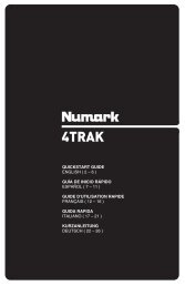
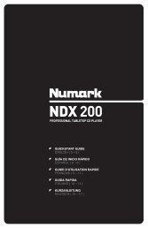
<strong>DJ</strong><strong>24</strong> FRONT PANEL DIAGRAM...<br />
7<br />
1<br />
11 2<br />
12<br />
9<br />
10<br />
8<br />
3<br />
4<br />
GUIDED TOUR OF FEATURES AND<br />
OPERATING INSTRUCTIONS...<br />
5<br />
13<br />
Please read this entire manual before you begin operation.<br />
INSTALLATION AND OPERATION<br />
Study the Connections Diagram on page 13. First,<br />
connect all stereo input sources. Next connect your<br />
microphone(s) and monitor headphones. Make sure all<br />
faders are at "zero" and the unit is off. Finally, connect the<br />
stereo outputs to the power amplifier(s) and/or audio<br />
sources. Plug the <strong>DJ</strong><strong>24</strong> into AC power. Now you are ready<br />
to switch it on.<br />
The <strong>DJ</strong><strong>24</strong> is divided into five functional blocks: Input,<br />
Crossfader, <strong>DJ</strong> Mic, Master/Zone Output, and Equalizer. It<br />
is important to learn how each of these work.<br />
CHANNEL INPUTS/CONTROLS SECTION<br />
1. Channels 1, 2, & 3 Input Toggle Switches<br />
select which source will be live to that channel based on<br />
what you have connected to the rear panel input section.<br />
2. The Input Faders are low-noise, low-impedance, highquality,<br />
smooth Alps faders. These control individual<br />
source levels in the mix.<br />
3. Channel Cue Assign. The Cue pushbuttons are<br />
used to route channel audio to the Monitor Section.<br />
The channel faders do not control the Cue send volume.<br />
6<br />
16<br />
14<br />
15<br />
17<br />
18<br />
CROSSFADER SECTION<br />
20<br />
26<br />
31<br />
19<br />
29<br />
28 27<br />
25<br />
30<br />
4. The Crossfader Assign knob to the left of the<br />
crossfader lets you choose which input channel will be<br />
heard when the crossfader is in the far left position.<br />
5. The Replaceable Crossfader achieves clean<br />
segues between the two selected input channels.<br />
<strong>Numark</strong> - The Proven Leader in <strong>DJ</strong> Technology<br />
Off1 2 3 Off1 2 3<br />
"Hard left" selects the channel set up of the Assign Left<br />
knob. In this example it is Channel 1. "Hard right" selects<br />
the channel set up on the Assign Right knob. In this<br />
example it is Channel 3. With the crossfader centered both<br />
assigned channels are live. Use the crossfader for fast and<br />
seamless segues from one selected channel to the other.<br />
To turn off the crossfader simply turn both knobs all the<br />
way to the left.<br />
Note: The crossfader is user replaceable in case of failure.<br />
Simply unscrew the two large screws which hold it in place,<br />
lift it out and disconnect it’s cable. Re-attach the new<br />
crossfader and screw the mounting plate back onto the<br />
unit - you’re back in business!<br />
6. The Crossfader Assign knob to the right of the<br />
crossfader lets you choose which input channel will be<br />
heard when the crossfader is in the far right position.<br />
©1998 <strong>Numark</strong> Industries 8 http://www.numark.com
<strong>DJ</strong> MIC SECTION<br />
The <strong>DJ</strong><strong>24</strong> has an extremely flexible <strong>DJ</strong> Mic channel. The<br />
Talkover function reduces the level of the music while<br />
leaving the <strong>DJ</strong> Mic at normal volume.<br />
7. Neutrik “Combo” connector allows connection of<br />
either a 1/4” jack or an XLR jack for the <strong>DJ</strong> Mic 1. This is<br />
ideal for connecting an XLR gooseneck directly into the<br />
mixer.<br />
8. Treble and Bass Controls fine tune the tone of<br />
your voice on both mics through the sound system. The<br />
controls are detented for setting tone "flat". For best<br />
results, use a dynamic cardioid microphone.<br />
9. The <strong>DJ</strong> Mic 1 Fader controls the <strong>DJ</strong> Mic volume for<br />
the Neutrik “Combo” connector.<br />
10. The Mic 2 Fader controls the Mic volume for the<br />
1/4” connector on the rear of the mixer.<br />
11.Mic Off/On/Talkover Switch.<br />
Off turns off Mic 1<br />
On turns on Mic 1<br />
Talkover turns down the input level of your music<br />
sources from Channels 1-4.<br />
Talkover is very useful for making announcements <strong>with</strong>out<br />
adjusting any levels.<br />
Try using this feature for audience participation<br />
when you want the music to temporarily cease<br />
and the audience to be heard - “YEAH!”<br />
MASTER/BOOTH OUTPUT SECTION<br />
12. The Stereo Master Fader controls the overall<br />
output level.<br />
<strong>Numark</strong> - The Proven Leader in <strong>DJ</strong> Technology<br />
<strong>DJ</strong><strong>24</strong><br />
13. Stereo/Mono toggle adjusts the Master output for<br />
the operation selected.<br />
14. The Booth Level controls speaker volume for a<br />
remote zone or booth monitors. If you do not use booth<br />
monitors the output can feed a tape deck, another<br />
amplifier, another mixer or a satellite speaker system.<br />
Note: This can also be used to supply line level audio to a<br />
lighting controller or to lights that are sound activated.<br />
CONTRACTOR'S NOTE: Booth Level provides<br />
zone control in installations where there are two separate<br />
rooms, or a bar and dance floor, for example. Remote zone<br />
volume should be controlled from the <strong>DJ</strong><strong>24</strong>.<br />
15. Stereo Auto Peak Hold Level Indicator. This<br />
fast, accurate stereo meter tracks the output level. The red<br />
LEDs for +3dB, +5dB and +8dB hold program peaks for a<br />
second or two. With peak metering, it's OK to be "in the<br />
red" as long as +5dB or +8dB aren't constantly lit. Set the<br />
crossover, equalizer and power amp inputs to avoid<br />
distortion at each step in the audio chain. Proper attention<br />
to the peak meter results in the punchiest possible sound<br />
<strong>with</strong>out audible distortion.<br />
©1998 <strong>Numark</strong> Industries 9 http://www.numark.com
<strong>DJ</strong><strong>24</strong><br />
EQUALIZER SECTION<br />
16. 5-Band Stereo Graphic Equalizer (EQ). EQ<br />
compensates for differences in source material sound<br />
quality. In ultra-compact mobile systems this EQ can be<br />
used to tailor the sound to the acoustical requirements of<br />
the room. Center frequencies are 63Hz, 250Hz, 1kHz,<br />
4kHz and 16kHz. Faders have a center detent for an<br />
accurate "flat” response.<br />
Below is a typical "house" EQ curve. Notice how the knobs<br />
above "0" balance out the knobs below. Start <strong>with</strong> this<br />
setting if you've never used a graphic EQ before:<br />
Below is an example of a poor EQ curve because it cuts the<br />
output volume down by 6-10dB. You have to compensate<br />
by running the Master output higher:<br />
Below is the worst sort of curve to use because you are<br />
using EQ to add volume. With exaggerated boost you can<br />
easily run your power amplifiers into “clipping” and damage<br />
your speakers.<br />
0<br />
0<br />
0<br />
GENERAL EQ HINTS<br />
• Boost the 63Hz band for deep bass tones and solid kick<br />
drum sound. Use sparingly because this dramatically<br />
increases demand on power amplifiers and could drive<br />
them into “clipping” .<br />
• Cut slightly at 250Hz and more at 1kHz for extra clarity.<br />
Note: Cutting is preferable to boosting.<br />
• Boost 16kHz for a little "sizzle".<br />
• As a general rule, less equalization is better!<br />
17. Equalizer On/Off. This controls whether your final<br />
output will be routed through the EQ or not.<br />
MONITOR SECTION<br />
18. The Monitor section includes the Program Mix<br />
control, the Headphone Volume control and the<br />
Headphone Jack. Connect headphones <strong>with</strong> a<br />
standard 1/4" stereo plug. The Cue audio is sent to the<br />
headphone amp using the Cue Assign Pushbutton<br />
and the Pgm Mix control. The Program Mix controls<br />
the amount of program audio in the headphones so that<br />
beats can be matched exactly and segues are smooth<br />
when a song is cued.<br />
19. 12V BNC Connector allows a 12 volt gooseneck<br />
lamp to be connected directly to the mixer. This light is<br />
readily available from your <strong>Numark</strong> dealer.<br />
20. Power Switch and Power-On LED.<br />
<strong>Numark</strong> - The Proven Leader in <strong>DJ</strong> Technology<br />
©1998 <strong>Numark</strong> Industries 10 http://www.numark.com
DIGITAL SAMPLER SECTION<br />
The <strong>Sampler</strong> uses dynamic RAM <strong>with</strong> a 12-bit<br />
microprocessor controller. The same digital signal<br />
processing components used in professional audio<br />
equipment deliver high-quality samples.<br />
25. The Mode Knob switches from effect to effect.<br />
Modes are:<br />
• Loop sets the unit to play back a sample and automatically<br />
repeat when it gets to the end of the sample.<br />
• Single sets the unit to play back a sample once.<br />
• Write sets the unit to sampler record ready. Depress the<br />
appropriate assign button to select the source you wish to<br />
record. Selecting a bank you wish to record to and hit the<br />
Start/Stop button (#30) to begin recording (it is safer to<br />
actually choose your bank before going to write mode so<br />
that you don't accidentally wipe out an existing sample). The<br />
LED will stay lit while you are in Write mode. After you are<br />
done writing your sample you should select a play mode<br />
(either Single or Loop) and listen to your sample.<br />
TO RECORD A SAMPLE<br />
a - Select the Write mode to go into stand by mode.<br />
b - Select the bank (or multiple banks) into which you want<br />
to record. Any bank can be selected. Each bank contains 6<br />
seconds of recording time. If you want to record a longer<br />
sample select multiple banks (they must be adjoining). To<br />
playback a multi-bank sample you must reselect the same<br />
banks later. Note: To overwrite an existing sample, select<br />
that bank instead of an empty bank. Changing bank<br />
selection at this point in time is possible and will not destroy<br />
any previously recorded samples.<br />
c - Hit the Start-Stop button to begin recording. The red<br />
LED will light.<br />
d- Hit Start-Stop a second time to stop the sampling, or<br />
allow the memory banks to fill up, at which time sampling will<br />
stop automatically. Once your writing is complete, switch to a<br />
playback mode. The sampler is now ready for playback.<br />
27. The Speed Control plays samples faster or slower<br />
resulting in a pitch shift of the sample. In the center position,<br />
the sample is played at recorded speed. Moving the knob to<br />
the left will slow down playback by up to 50%; moving the<br />
knob to the right will speed up the playback by up to 200%.<br />
Positions near the center provide fine changes in playback<br />
speed. Positions further from the center detent provide<br />
more drastic changes in playback speed.<br />
<strong>Numark</strong> - The Proven Leader in <strong>DJ</strong> Technology<br />
<strong>DJ</strong><strong>24</strong><br />
28. Effect Level Mix fader. This precisely sets<br />
the audible level of the sample in the mix.<br />
29. Memory Bank Select Pushbuttons A-D.<br />
Four banks are available for storing samples. To<br />
record a bank go to Write and then hit the bank<br />
button. You can record into any combination of banks<br />
by pressing multiple bank buttons. After sampling,<br />
you can either select the next bank and record it<br />
(remember Write is still on, just select the bank and<br />
hit Start/Stop) or you can manually select a playback<br />
mode.<br />
• You can play any combination of the Memory Banks<br />
from left to right (that is, Memory Bank B will always<br />
play before Memory Bank D - but you can play ABCD;<br />
BC; BD: ACD; only C; only D; etc.).<br />
30. The large Start-Stop button controls sample<br />
recording and sample playback. The small red Effects<br />
Indicator LED glows when the sampler is "on". Here<br />
are the functions:<br />
• Tap the button when in sampler Write mode to<br />
begin sampling (the LED will light). Tapping it again<br />
ends the sample and the LED goes out. (unless the<br />
sampler has run out of memory and shuts off<br />
automatically.<br />
• In single or loop play <strong>with</strong>out Trigger, tap the<br />
button to play the sample and tap it again to stop the<br />
playback. Every time you play the sample, the music<br />
starts from the beginning of the sample.<br />
• In Single or Loop play <strong>with</strong> Trigger you are<br />
ready to "stab" samples. With the Trigger Out, the<br />
sample plays all the way through before you can play it<br />
again. With it In, you can stab or stutter a sample.<br />
When you shout "Rock it - rock the house!" and<br />
sample it, it can be played back as -<br />
R-R-R-R-R-R-R-Rock --<br />
Rock-Rock-Rock it - Rock it Rock it -<br />
Rock - - Rock it - rock the house!<br />
by simply "drumming" <strong>with</strong> your fingers.<br />
31. Monitor Pushbutton. To hear the sample or<br />
effect in the headphones, press this button.<br />
Program Mix still works and you will be able to hear<br />
any other input channels <strong>with</strong> the Cue buttons<br />
activated.<br />
©1998 <strong>Numark</strong> Industries 11 http://www.numark.com
<strong>DJ</strong><strong>24</strong><br />
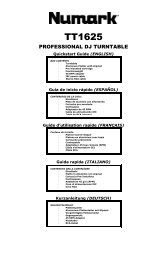
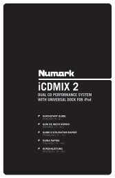
<strong>DJ</strong><strong>24</strong> REAR PANEL DIAGRAM...<br />
1<br />
4 5 3<br />
REAR PANEL: INPUTS AND OUTPUTS<br />
1. AC Cord. See safety precautions on page 3 for<br />
proper treatment of the power cord.<br />
2. GND is the grounding lug for turntables 1 and 2<br />
(phono inputs on Channels 1 and 2). Always use this<br />
connection (your turntable cable should have a<br />
grounding wire).<br />
3. The Stereo Main Outputs are low-impedance<br />
RCA connectors controlled by the Master fader.<br />
4. The Stereo Zone Outputs are low-impedance<br />
unbalanced RCA jacks controlled by the Zone Level<br />
control.<br />
5. The Tape Outputs are low-impedance<br />
unbalanced RCA jacks which output the program mix<br />
and allow you to connect any recording device.<br />
6. Mic 2 is a high-impedance 1/4” input.<br />
7 7 7 8 7<br />
<strong>Numark</strong> - The Proven Leader in <strong>DJ</strong> Technology<br />
7. Channels 1-3 Line Inputs are unbalanced RCA<br />
jacks. The Line Input is selected <strong>with</strong> the toggle<br />
switch on the front panel.<br />
You can connect stereo audio from HiFi VCRs, cassette<br />
and reel-to-reel tape decks, DAT machines, CD players,<br />
laser discs, tuners, even synthesizers or other mixing<br />
consoles.<br />
NOTE: Plug mono audio sources into both Left and<br />
Right inputs using a “Y” cable connector.<br />
8. Phono Inputs on Channels 1 and 2 use<br />
unbalanced RCA jacks. Your input signal is fed directly<br />
to the <strong>DJ</strong><strong>24</strong>'s high-quality RIAA phono pre-amplifiers<br />
so use this position only for moving magnet cartridges.<br />
Line level sources will overload the sensitive phono<br />
pre-amps and will sound very bad, so always be sure to<br />
toggle the line/phono switch over to line before<br />
connection of line sources.<br />
©1998 <strong>Numark</strong> Industries 12 http://www.numark.com<br />
8<br />
6<br />
2
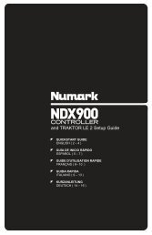
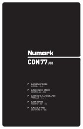
<strong>DJ</strong><strong>24</strong> CONNECTION DIAGRAM...<br />
Tape Deck<br />
AC<br />
Outlet<br />
Zone<br />
Sound System<br />
w/ Amplifier<br />
Main<br />
Sound System<br />
w/ Amplifier<br />
Tape Deck<br />
Turntable 1<br />
Microphone 2<br />
CD Player Turntable 2<br />
<strong>Numark</strong> - The Proven Leader in <strong>DJ</strong> Technology<br />
©1998 <strong>Numark</strong> Industries 13 http://www.numark.com<br />
<strong>DJ</strong><strong>24</strong>
<strong>DJ</strong><strong>24</strong><br />
SPECIFICATIONS...<br />
INPUTS:<br />
Line:10kΩ input impedance<br />
80 mV rms sensitivity (for 1.22 V output)<br />
Mic: 10kΩ input impedance balanced/unbalanced<br />
2.5 mV rms sensitivity (for 1.22 V output)<br />
500 mV rms max input<br />
Phono:47kΩ input impedance<br />
1.5 mV rms sensitivity @ 1 KHz (for 1.22 V output)<br />
OUTPUTS:<br />
Line: 9V rms max (+20 dBm)<br />
Headphone Amp: .5 watt into 47Ω<br />
Distortion less than .01%<br />
EQUALIZER:<br />
5-Band Stereo Graphic EQ<br />
Band centers 63Hz, 250Hz, 1KHz, 4KHz, 16KHz +/- 12 dB<br />
SIGNAL TO NOISE RATIOS (vs. maximum output):<br />
Line: Better than 85 dB<br />
Mic: Better than 72 dB<br />
Phono: Better than 83 dB<br />
FREQUENCY RESPONSE:<br />
Mic: 20 Hz- 15k Hz +_ .5 dB<br />
Line: 20 Hz- 20k Hz +_ .5 dB<br />
Phono: +_ 1 dB except for controlled attenuation of -3 dB<br />
@ 20 Hz to reduce rumble and feedback<br />
TALKOVER ATTENUATION:<br />
variable from no cut to -16 dB<br />
POWER CONSUMPTION:<br />
20 Watt typical, 28 Watt <strong>with</strong> full headphone output<br />
<strong>Numark</strong> - The Proven Leader in <strong>DJ</strong> Technology<br />
©1998 <strong>Numark</strong> Industries 14 http://www.numark.com
BLOCK DIAGRAM...<br />
<strong>Numark</strong> - The Proven Leader in <strong>DJ</strong> Technology<br />
©1998 <strong>Numark</strong> Industries 15 http://www.numark.com<br />
<strong>DJ</strong><strong>24</strong>
Professional Disc Jockey Products<br />
Warranty and Service Information<br />
<strong>Numark</strong> Industries, LLC and <strong>Numark</strong> International, Inc. (hereafter “<strong>Numark</strong>”)<br />
warrants each new product manufactured and/or supplied by it to be free from<br />
defects in material or workmanship under conditions of normal use and service for<br />
360 days, beginning on the date of purchase from an authorized <strong>Numark</strong> Dealer,<br />
but not to exceed 2 years from date of shipment by <strong>Numark</strong>.<br />
The <strong>Numark</strong> obligation under this warranty is limited to repairing or replacing, at<br />
its option, the product or part(s) therein; which upon examination by <strong>Numark</strong> shall<br />
appear to be defective or not up to factory specifications; providing the <strong>Numark</strong><br />
product is returned (transportation prepaid) to <strong>Numark</strong>.<br />
<strong>Numark</strong> shall not be liable for any damages, consequential or otherwise,<br />
resulting from the use and operation of this product and makes no other warranty(s)<br />
either express or implied on this product, including any warranty of merchantability.<br />
This warranty does not extend to any of our products which have been<br />
subjected to misuse, neglect, accident, incorrect wiring not our own, improper<br />
installation, or use in violation of instructions furnished by us, nor extended to units<br />
which have been repaired or altered outside of our factory, nor to cases where the<br />
serial number thereof has been removed, defaced, or changed, nor to accessories<br />
used there<strong>with</strong> not of our own manufacture. <strong>Numark</strong> reserves the right to make<br />
changes or improvements in its products, during subsequent production, <strong>with</strong>out<br />
incurring the obligation to install such changes or improvements on previously<br />
manufactured equipment.<br />
To place this warranty into effect, the enclosed WARRANTY REGISTRATION<br />
CARD must be returned to <strong>Numark</strong> Industries, LLC <strong>with</strong>in thirty (30) days after<br />
date of purchase.<br />
This warranty gives you specific legal rights, and you may also have other<br />
rights which vary from state to state.<br />
Some states do not allow the exclusion or limitation of incidental or<br />
consequential damages so the above limitation or exclusion may not apply to you.<br />
EQUIPMENT TRANSPORT<br />
A Return Authorization number should be obtained from <strong>Numark</strong> through the<br />
addresses or phone numbers below.<br />
It is the customer’s obligation, when returning faulty equipment, to properly<br />
pack the <strong>Numark</strong> equipment in its original packaging. Failure to do so may<br />
inadequately protect the equipment in transit and, therefore, jeopardize the<br />
customer’s warranty. The defective <strong>Numark</strong> equipment should be sent, FREIGHT<br />
PREPAID <strong>with</strong> Return Authorization number to:<br />
NUMARK INDUSTRIES<br />
11 Helmsman Road<br />
North Kingstown, RI 02852 USA<br />
Attention: Service Department<br />
Telephone: +1 (401) 295-9000<br />
Fax: +1 (401) 295-5200<br />
E-mail: numark@numark.com