Spindle Assembly Removal - Little Machine Shop
Spindle Assembly Removal - Little Machine Shop
Spindle Assembly Removal - Little Machine Shop

You also want an ePaper? Increase the reach of your titles
YUMPU automatically turns print PDFs into web optimized ePapers that Google loves.
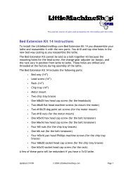
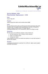
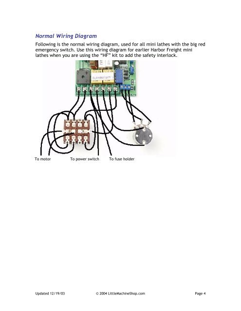
Normal Wiring Diagram<br />
Following is the normal wiring diagram, used for all mini lathes with the big red<br />
emergency switch. Use this wiring diagram for earlier Harbor Freight mini<br />
lathes when you are using the “HF” kit to add the safety interlock.<br />
To motor To power switch To fuse holder<br />
Updated 12/19/03 © 2004 <strong>Little</strong><strong>Machine</strong><strong>Shop</strong>.com Page 4
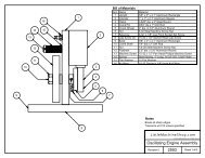
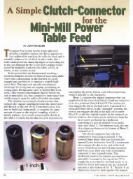
FC250J/110V<br />
Controller<br />
Wiring diagram for standard late model 7x12 mini lathe<br />
with red and yellow emergency stop switch.<br />
DC<br />
Output<br />
- +<br />
AC<br />
Input<br />
1 2 3 4 5 6 7<br />
P1 P2 P3 P4<br />
Rev<br />
Potentiometer<br />
Off<br />
For Black<br />
F/O/R<br />
Switch<br />
Fuse<br />
White<br />
Power<br />
Cord<br />
Motor<br />
Emergency<br />
Switch<br />
<strong>Little</strong><strong>Machine</strong><strong>Shop</strong>.com<br />
Wiring Diagram, Mini Lathe<br />
Revision 0<br />
2506<br />
© 2005 <strong>Little</strong><strong>Machine</strong><strong>Shop</strong>.com. All rights reserved.<br />
Sheet 1 of 1