to download the AX7 heatpump manual. - Air Trade Centre
to download the AX7 heatpump manual. - Air Trade Centre
to download the AX7 heatpump manual. - Air Trade Centre

Create successful ePaper yourself
Turn your PDF publications into a flip-book with our unique Google optimized e-Paper software.
ALL IN ONE<br />
Heat Pump Water Heater<br />
INSTALLATION AND OPERATION INSTRUCTIONS<br />
Please read this user’s <strong>manual</strong> carefully before operate <strong>the</strong> unit.<br />
www.airtradecentre.com
CONTENTS<br />
A. IMPORTANT REMARKS ------------------------------------------------------------------------------------------------ 1<br />
B. DESCRIPTION OF HEAT PUMP ------------------------------------------------------------------------------------- 2<br />
C. INSTALLATION INSTRUCTION------------------------------------------------------------------------------------ 3-5<br />
D. OPERATION PANEL INSTRUCTION----------------------------------------------------------------------------- 6-9<br />
E. MAINTENANCE AND SERVICE -------------------------------------------------------------------------------- 10-11<br />
F. UNIT CIRCUIT DIAGRAM-----------------------------------------------------------------------------------------12-13<br />
WARNING:<br />
1. This unit must be installed by <strong>the</strong> professional persons, dealers or special installation<br />
companies authorized. Or o<strong>the</strong>rwise, accidents maybe possibly caused and use effect maybe<br />
possibly be affected.<br />
2. Be sure that <strong>the</strong> unit is STOP operation when disconnecting <strong>the</strong> power supply <strong>to</strong> <strong>the</strong><br />
unit .Disconnect all electric power supplies before servicing.<br />
3. This appliance is not intended for use by persons (including children) with reduced physical,<br />
or lack of experience and knowledge, unless <strong>the</strong>y have been given supervision or instruction<br />
concerning use of <strong>the</strong> appliance by a person responsible for <strong>the</strong>ir safety.<br />
4. Children should be supervised <strong>to</strong> ensure that <strong>the</strong>y do not play with <strong>the</strong> appliance.<br />
5. If <strong>the</strong> supply cord is damaged, it must be replaced by <strong>the</strong> manufacturer or its service agent or<br />
a similarly qualified person in order <strong>to</strong> avoid a hazard.
A. Important remarks<br />
Thank you for choosing our products. Before installation, it is strongly recommended <strong>to</strong> read<br />
this instruction firstly. This <strong>manual</strong> includes <strong>the</strong> information of installation, debugging,<br />
running and maintenance of <strong>the</strong> products.<br />
Every unit of products has passed strictly test <strong>to</strong> ensure safety and high efficiency operation.<br />
The manufacturer of this product will not be held responsible if someone is injured or <strong>the</strong> unit<br />
is damaged, as a result of improper installation, debugging, and unnecessary maintenance<br />
which is not in line with this <strong>manual</strong>.<br />
The installer should be an authorized technician, and install <strong>the</strong> system follow <strong>the</strong> diagram<br />
on <strong>the</strong> equipment.<br />
Please notice <strong>the</strong> following information during installation:<br />
1. Applied working temperature of heat pump: -7~43℃.<br />
2. Check whe<strong>the</strong>r <strong>the</strong> power supply and wire meet <strong>the</strong> standard of <strong>the</strong> unit.<br />
3. Do not alter <strong>the</strong> power wire or socket and <strong>the</strong> metal parts should be connected <strong>to</strong> GND well. Do<br />
not change <strong>the</strong> GND connection of <strong>the</strong> system.<br />
4. The appliance shall be installed in accordance with national wiring regulations.<br />
5. When <strong>the</strong> system is connected <strong>to</strong> a fixed power supply, a 3mm space switch should be equipped.<br />
6. When finish all <strong>the</strong> wiring, check it again before power on.<br />
7. Do not install <strong>the</strong> system in <strong>the</strong> warehouse where flammable gas may leak out.<br />
8. Do not insert hands or object in<strong>to</strong> <strong>the</strong> vent of <strong>the</strong> heat pump, it may cause <strong>the</strong> dangerous <strong>to</strong><br />
people or damage <strong>the</strong> system.<br />
9. To make <strong>the</strong> system more efficiency, please install <strong>the</strong> main unit at a place with good ventilation.<br />
10. Do not put (or install) <strong>the</strong> operating panel at a wet place, do not cut and reconnect <strong>the</strong><br />
connecting wire.<br />
11. Before turn on <strong>the</strong> system at a first time, ensure <strong>the</strong> water tank is full filled with water.<br />
12. The inlet of <strong>the</strong> water tank equips with a filter (detachable), clean it according <strong>to</strong> <strong>the</strong> water quality<br />
and running condition of <strong>the</strong> system (<strong>the</strong> period should be 2~3 months)<br />
13. While <strong>the</strong> water supply has been s<strong>to</strong>pped or <strong>the</strong> system s<strong>to</strong>ps running for a long period in winter,<br />
should be drain <strong>the</strong> tank water <strong>to</strong> avoid water system frost crack.<br />
14. The highest temperature of outing water is 60℃, when using, tune up <strong>to</strong> a suitable temperature<br />
(<strong>the</strong> most suitable temperature for human is 38~45℃, if <strong>the</strong> temperature is higher than 55℃, it<br />
may cause <strong>the</strong> danger of scald). Normally, <strong>the</strong> setting temperature can be from 10℃ - 60℃, <strong>the</strong><br />
model with Auxiliary heater can reach up <strong>to</strong> 70℃.<br />
15. Move <strong>the</strong> main unit at max. 30 degree angle. Do not drop down or upend <strong>the</strong> unit.<br />
16. The unit needs <strong>to</strong> be checked and maintained 1 time per year by a qualified service man.<br />
And disconnect all power when servicing.<br />
17. The purpose of <strong>the</strong> magnesium bar is <strong>to</strong> protect <strong>the</strong> tank, it's an additional part. According <strong>to</strong> <strong>the</strong><br />
water quality, it is recommendable <strong>to</strong> replace <strong>the</strong> bar every 1 or 1,5 years <strong>to</strong> increase <strong>the</strong> life time<br />
of <strong>the</strong> stainless steel tank. The warranty on <strong>the</strong> unit is only valid if <strong>the</strong> bar is replaced on a regular basis.<br />
18. Please provide <strong>the</strong> warrantee card and S/N No. enclosed with <strong>the</strong> product for after service.<br />
1
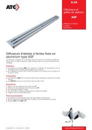
B. Description of heat pump<br />
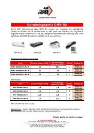
Unit constructions (outside):<br />
Top Cover 顶 盖<br />
Upper 主 机 Cover 上 壳<br />
流 溢 孔<br />
Condensate Overflow Hole<br />
Vent 出 风 Pipe 管<br />
Ventilation 风 机 Fan<br />
Host 主 Chassis 机 底 盘<br />
底 盘 安 装 板<br />
Chassis Installation board<br />
Hot Water 热 水 Outlet 出 口<br />
循 环 水 口<br />
Circulation Water Hole<br />
Tank 水 箱 Cover 外 壳<br />
Hand 抽 Grip 手<br />
Circulation Water Hole<br />
循 环 水 口<br />
Condensate Drain Hole<br />
冷 凝 水 口<br />
Cold Water Inlet /<br />
进 排 水 口<br />
Drainage Hole<br />
Supporting frame 底 脚<br />
<strong>Air</strong> Inlet / Outlet<br />
Screen 操 作 面 Panel 板<br />
Decoration 装 饰 条 Bar<br />
Electric 电 器 盒 Board<br />
Compressor 压 缩 机<br />
Evapora<strong>to</strong>r 蒸 发 器<br />
Left/Right 左 右 装 饰 Decoration 条 Bar<br />
Decoration 装 饰 板 Panel<br />
Magnesium 镁 棒 口 Hole<br />
Electric 电 加 热 Heater 盖 Cover<br />
Electric 电 加 热 Heater 口 Hole<br />
Polyurethane 发 泡 层 Layer<br />
Condenser 盘 管 coil<br />
Remark:<br />
1. The above drawing is for reference <strong>to</strong> identify <strong>the</strong> name of each part. Details are subject <strong>to</strong> real unit.<br />
2. The drawing of “Electric Heater hole” is only for <strong>the</strong> unit with Auxiliary heater models; o<strong>the</strong>r models<br />
without auxiliary heater function are not available.<br />
3. There are two “Circulation Water Hole” for optional connection. It can be available when <strong>the</strong> user<br />
requests an external connection for hot water circulation. Normal models are without <strong>the</strong>se holds.<br />
2
CLOCK ON/OFF<br />
TIMER MODE<br />
ON/OFF<br />
CLOCK ON/OFF<br />
TIMER MODE<br />
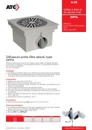
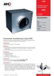
C. Installation instruction<br />
Note:<br />
1. This heat pump unit can be installed at veranda, hallway or o<strong>the</strong>r place where is easy <strong>to</strong> install and<br />
stable. The air inlet and outlet are at <strong>the</strong> <strong>to</strong>p side, main unit should not be placed at an open air. Avoid<br />
<strong>the</strong> rain or debris <strong>to</strong> enter <strong>the</strong> vents. The air inlet and outlet can connect <strong>the</strong> φ150mm air duct.As below,<br />
≥800mm<br />
CLOCK<br />
MODE≥800mm<br />
TIMER<br />
≥600mm<br />
≥600mm<br />
≥500mm<br />
(Fig.1)<br />
(Fig.2)<br />
2. When install as Fig.1, only connect <strong>the</strong> air inlet or outlet, <strong>the</strong> unit should be installed at a place of<br />
ventilation, and <strong>the</strong> side connected with water pipes should has enough space. Then, if <strong>the</strong> unit is<br />
installed besides <strong>the</strong> room, it can be connected <strong>the</strong> air outlet duct <strong>to</strong> <strong>the</strong> room for exchange fresh air<br />
and cooling function; If <strong>the</strong> unit is installed in <strong>the</strong> room, it can be pulled out room’s air for ventilation<br />
function.<br />
3. If install as Fig. 2, <strong>the</strong> unit can be installed by <strong>the</strong> middle of <strong>the</strong> wall, and connect <strong>the</strong> air inlet and outlet<br />
pipe for air exchange. The distance of <strong>the</strong> unit and wall or o<strong>the</strong>r obstacle should not be <strong>to</strong>o short. Keep<br />
a certain distance.<br />
4. If install as Fig. 3, <strong>the</strong> unit is installed outside <strong>the</strong> room, <strong>the</strong><br />
air inlet and outlet is connected indoor for air exchange<br />
(and cooling). In this way, <strong>the</strong> indoor air inlet and outlet<br />
should have a distance ≥2m <strong>to</strong> avoid mix air.<br />
5. Because <strong>the</strong> air outlet comes with cooling air, <strong>the</strong> surface<br />
of <strong>the</strong> pipe may have condensation water, it’s necessary <strong>to</strong><br />
≥600mm<br />
insulate <strong>the</strong> indoor outlet pipe <strong>to</strong> prevent water leakage.<br />
6. Heat pump water heater unit must be placed upright, and<br />
installed on a solid place where can be able <strong>to</strong> withstand<br />
<strong>the</strong> weight over 700kgs. Supporting surface should be<br />
evenness (obliquity less than 2°)<br />
7. When install <strong>the</strong> unit, <strong>the</strong>re should has some measures of<br />
sound insulation and shockproof in order not <strong>to</strong> affect<br />
neighbors. (Fig. 3)<br />
≥800mm<br />
3
C. Installation instruction<br />
8. When unit operation, put <strong>the</strong> unit in a well-ventilated place and non-blocking <strong>the</strong> air vent, so that <strong>the</strong><br />
machine can be able <strong>to</strong> inhale and exhaust enough air, <strong>to</strong> achieve hot water supply function.<br />
9. There should be with drain around <strong>the</strong> system unit for drainage. And <strong>the</strong> surrounding should have<br />
enough space for maintenance. Because <strong>the</strong> <strong>to</strong>p cover can be opened, at <strong>the</strong> <strong>to</strong>p side of <strong>the</strong> unit<br />
should have ≥800mm space for maintain.<br />
10. Nearby <strong>the</strong> system unit, <strong>the</strong>re should be reserved a water supply pipe and hot water pipe interface<br />
equipped with valves, <strong>the</strong> water inlet pipe should be with filter (for cleaning).<br />
11. For waterway connection of this integrated unit, please refer <strong>to</strong> <strong>the</strong> following “Waterway installation<br />
diagram”. Follow with <strong>the</strong> system unit, <strong>the</strong>re are Three-port valve, Safety valve and Filter. Connect<br />
<strong>the</strong>m <strong>to</strong> <strong>the</strong> water inlet and outlet of <strong>the</strong> unit.<br />
12. If <strong>the</strong> Heat pump equip with “Circulation Water Hole” (optional), It can be connected with SOLAR<br />
WATER HEATER, HEAT RECOVERY SYSTEM and o<strong>the</strong>r water heating equipment <strong>to</strong> heat <strong>the</strong> water<br />
tank by circulation. Retain original if no need external connection.<br />
13. The working pressure of this water heater tank must ≤0.7MPa. Water inlet must connect <strong>the</strong> safety<br />
valve, and its operation pressure is 0.7MPa, Connect ano<strong>the</strong>r end of <strong>the</strong> safety valve <strong>to</strong> water supply<br />
pipe. The safety valve should be connected by a small rubber pipe interlinked with atmosphere; this<br />
pipe must not be blocked, in order <strong>to</strong> drain <strong>the</strong> water when <strong>the</strong> tank’s pressure exceeds 0.7MPa.<br />
14. Water inlet pressure should >0. 1MPa, if <strong>the</strong> pressure is lower, can connect <strong>the</strong> pressure pump on<br />
inlet pipe <strong>to</strong> get <strong>the</strong> high water flow.<br />
15. Ensure <strong>the</strong> water tank is full fill with water before turn on <strong>the</strong> system: First, open <strong>the</strong> valve on <strong>the</strong><br />
water supply inlet, <strong>the</strong>n switch on ei<strong>the</strong>r valve of <strong>the</strong> water outlet, and <strong>the</strong>n you can affuse water <strong>to</strong> <strong>the</strong><br />
tank until <strong>the</strong> water overflow <strong>the</strong> water outlet valve. After which you can turn off <strong>the</strong> water outlet valve<br />
and check for leakage. Make sure <strong>the</strong>re is no water leaking.<br />
NOTE: For <strong>the</strong> first time use, ensure <strong>the</strong> water tank has been filled with water before turn on <strong>the</strong><br />
system.<br />
16. In order <strong>to</strong> ensure <strong>the</strong> water tank filled with water, require a certain section of hot water outlet side<br />
should be about 10cm higher than <strong>the</strong> water heater tank section.<br />
17. The water heater temperature <strong>the</strong>rmal sensor was put and sealed well in a tank by <strong>the</strong> fac<strong>to</strong>ry before<br />
launch <strong>to</strong> market. No need <strong>to</strong> install it when installation.<br />
18. This water heater unit is filled with refrigerant by <strong>the</strong> fac<strong>to</strong>ry, and no need <strong>to</strong> vacuumize or refill<br />
refrigerant.<br />
19. In <strong>the</strong> winter cold regions, <strong>the</strong> water heater unit can not turn off <strong>the</strong> power, if <strong>the</strong> system s<strong>to</strong>ps running<br />
for a long period in winter, should be drain <strong>the</strong> tank water <strong>to</strong> avoid water pipe or tank frost crack.<br />
Meanwhile, we should streng<strong>the</strong>n or check <strong>the</strong> external pipe <strong>to</strong> prevent <strong>the</strong> pipe frozen.<br />
4
CLOCK<br />
TIMER<br />
ON/OFF<br />
MODE<br />
C. Installation instruction<br />
Installation diagram:<br />
<strong>Air</strong> Outlet<br />
出 风<br />
Vent 风 Tube 管<br />
<strong>Air</strong>进 Inlet 风<br />
Hot Water Outlet<br />
热 水 出<br />
(Hot Water ( 用 水 use) 端 )<br />
溢 流 水 管<br />
Condensate Overflow drain<br />
热 循 环 进 水<br />
Heat Circulation water inlet<br />
热 循 环 出 水<br />
Heat Circulation water outlet<br />
Water ( 自 Supply 来 水 端 )<br />
Filter 过 滤 器<br />
冷 Water 水 进 Inlet<br />
安 全 阀<br />
Safety Valve<br />
冷 凝 水 排 出<br />
Condensate water drainage<br />
Ball Valve 球 阀<br />
Three-port Valve<br />
三 通<br />
排 Drainage 污 管 Pipe<br />
Remark:<br />
1. For <strong>the</strong> first time use, ensure <strong>the</strong> water tank have been filled with water before power on <strong>to</strong> prevent<br />
burn out.<br />
2. Follow with <strong>the</strong> water heater unit, <strong>the</strong>re are Three-port valve, Safety valve and Filter (see <strong>the</strong> annex<br />
detail list of parts). As for o<strong>the</strong>r water system components, <strong>the</strong> user or installation company should<br />
provide by <strong>the</strong>mselves.<br />
3. Before installation, it’s better <strong>to</strong> reserve a water supply pipe interface, hot water outlet pipe interface<br />
and drainage pipe interface. Among <strong>the</strong>m, <strong>the</strong> water supply pipe and hot water outlet pipe should be<br />
used in line with standards for drinking water pipes. (E.g. PPR pipe or stainless steel pipe, etc.), can<br />
not use iron pipe or <strong>the</strong> rubber hose with odor for installation.<br />
4. If <strong>the</strong> using place below 0 ℃ , make sure <strong>to</strong> insulate <strong>the</strong> water pipes <strong>to</strong> prevent frozen.<br />
5. <strong>Air</strong> inlet /outlet can connect Φ150mm vent tube, but pipe should not be <strong>to</strong>o long and less crankle.<br />
5
D. Operation panel instruction<br />
1. Panel - Operation:<br />
6
D. Operation panel instruction<br />
2. Panel - Display:<br />
Set 设 Temperature 定 水 温 显 示<br />
High 水 Temperature 温 高 温 提 示<br />
机 器 报 Alarm 警 指 示<br />
Auxiliary 辅 电 加 Heater 热 指 示<br />
Status 机 器 状 态 指 示<br />
HTG: Heating<br />
DEF: Defrost<br />
WARM: Keep warm<br />
工 Working 作 模 式 Mode 指 示<br />
Time 调 节 adjustment 时 钟 指 示<br />
当 前 时 间 Time 显 示<br />
定 时 开 Timer 显 示 On<br />
定 时 关 Timer 显 示 Off<br />
定 Timer 时 时 段 Period 显 示<br />
Water 用 水 Temperature 温 度 显 示<br />
Temperature 水 温 渐 Gradient 变 显 示<br />
注 : 当 用 水 温 度 超 过 55℃ 时 , 显 示 屏 上 " 高 温 " 提 示 亮 。<br />
Note: When <strong>the</strong> water temperature exceeds 55℃, <strong>the</strong> indica<strong>to</strong>r light<br />
on display.<br />
7
D. Operation panel instruction<br />
3. Parameter Setting:<br />
Press “MODE” but<strong>to</strong>n for 5 seconds; enter <strong>the</strong> Parameter setting status, <strong>the</strong> main parameter code as<br />
below sheet:<br />
Type Code Parameter Name Setting Range Fac<strong>to</strong>ry Setting Unit Remark<br />
Temperature<br />
Control<br />
F11 Setting temperature 5-70 55 °C<br />
F12 Difference in Temp. 1 - 30 5 °C<br />
F13<br />
Determine Heat pump s<strong>to</strong>p<br />
ambient temp.<br />
-10 – 5 -7 °C<br />
F14 Highest temp. for heat pump 40 – 60 55 °C<br />
F15<br />
F16<br />
F17<br />
Turn on or off electric<br />
heater mode<br />
Ambient temp. for start electric<br />
heating<br />
Turn on or off electric heater for<br />
sterilization function<br />
0 - 1 1 -<br />
-10 - 20 0 °C<br />
0-1 1<br />
F18 Sterilization cycle 1-990 336 hour<br />
F19<br />
Water <strong>the</strong>rmal sensor<br />
temp. amendment<br />
-5 – 5 0 °C<br />
Compressor F21 Compressor start delay 0 – 10 3 minute<br />
Defrost<br />
Alarm<br />
Function<br />
F31 Defrost start temp. -20 – 20 -2 °C<br />
F32 Defrost finish temp. 0 – 50 25 °C<br />
F33 Defrost start time 1 – 999 45 minute<br />
F34 Max. defrost time Off, 1 – 99 10 minute<br />
F50 Low pressure alarm mode 0 - 2 2 -<br />
F51<br />
F52<br />
F54<br />
Au<strong>to</strong> resume times of low<br />
pressure alarm<br />
Reset time of external alarm<br />
au<strong>to</strong> resume times<br />
Electric heater overheat<br />
protection<br />
0 – 10 3 time<br />
0 – 999 60 minute<br />
0 - 2 2 -<br />
F55 Overheat resume time 0-10 3 -<br />
F56 Alarm resume time 0-999 60 °C<br />
F57 Exhaust temp. protection mode 0 – 2 1 -<br />
F58 Exhaust protect temp. 50 – 125 110 °C<br />
F59<br />
Exhaust temp. protection<br />
Return difference<br />
1 – 30 10 °C<br />
F61 Memory status when power off Yes/No Yes -<br />
Setting F69 Communication baud 24/48 24 -<br />
System<br />
Setting<br />
F80<br />
Password<br />
OFF<br />
0001 -- 9999<br />
4321 -<br />
F85 Display sterilization <strong>to</strong>tal time - - hour<br />
Testing F98 Force defrosting (refrigeration)<br />
Control panel<br />
display “AdF”<br />
“OFF” means no<br />
password.<br />
Set “0000” <strong>to</strong><br />
clear password.<br />
Start compressor, 4-way valve<br />
and fan mo<strong>to</strong>r. Press any key<br />
<strong>to</strong> exit or 20 minutes it will exit<br />
au<strong>to</strong>matic.<br />
Remark: When enter Parameter setting status, press “up” or “down” <strong>to</strong> choose parameter code; after choose one,<br />
press “Timer” but<strong>to</strong>n <strong>to</strong> show this code’s setting value, and press “up” or “down” can set <strong>the</strong> value; After finish setting,<br />
press “Timer” but<strong>to</strong>n <strong>to</strong> confirm and return <strong>to</strong> Parameter code status.<br />
8
D. Operation panel instruction<br />
4. Error Handling:<br />
ERROR CODE ERROR STATUS REASONS ERROR HANDLING<br />
A1<br />
Thermal sensor alarm<br />
Water temp. sensor open circuit<br />
or short circuit.<br />
1. Check <strong>the</strong> water temp. sensor<br />
connection.<br />
2. Change <strong>the</strong> water temp. sensor.<br />
A2<br />
Condenser coil sensor<br />
alarm<br />
Condenser coil temp.sensor<br />
open circuit or short circuit.<br />
1. Check <strong>the</strong> condenser coil temp.<br />
sensor connection.<br />
2. Change <strong>the</strong> coil sensor.<br />
A3<br />
Exhaust sensor alarm<br />
Exhaust temp. sensor open<br />
circuit or short circuit.<br />
1. Check <strong>the</strong> exhaust temp. sensor<br />
connection.<br />
2. Change <strong>the</strong> exhaust temp. sensor.<br />
A4<br />
Ambient temp. sensor<br />
alarm<br />
Ambient temp. sensor open<br />
circuit or short circuit.<br />
1. Check <strong>the</strong> Ambient temp. sensor<br />
connection.<br />
2. Change <strong>the</strong> ambient temp. sensor.<br />
A5<br />
Low /High pressure<br />
alarm<br />
1.1. High pressure protection<br />
switch off.<br />
1.2. Ambient temp. <strong>to</strong>o high or<br />
water heat exchanger dirty<br />
block.<br />
2.1. Low pressure protection<br />
switch off.<br />
2.2. Leakage of refrigerant.<br />
1.1Check or change <strong>the</strong> high pressure<br />
protec<strong>to</strong>r.<br />
1.2. Check if <strong>the</strong> surround temp. is <strong>to</strong>o<br />
high, or clean <strong>the</strong> heat exchanger<br />
of water tank.<br />
2.1. Check or change <strong>the</strong> low pressure<br />
protec<strong>to</strong>r.<br />
2.2. Supply refrigerant and check if<br />
<strong>the</strong>re is any leakage.<br />
A6<br />
(Auxiliary) electric<br />
heater protection<br />
overheat alarm<br />
1. Electric heater protection<br />
switch off.<br />
2. Tank water temp. <strong>to</strong>o high.<br />
1. Check if <strong>the</strong> water temp. is as LCD<br />
display, or if water temp. is <strong>to</strong>o high.<br />
2. Change <strong>the</strong> Electric heater.<br />
A7<br />
Exhaust temperature<br />
<strong>to</strong>o high<br />
1. Lack of refrigerant.<br />
2. Mix with air in system.<br />
3. Lack of lubricating oil.<br />
1. Supply refrigerant.<br />
2. Re-vacuumizing, and fill in<br />
refrigerant.<br />
3. Change <strong>the</strong> lubricating oil of<br />
compressor.<br />
- -<br />
Screen no display or<br />
display insufficiency<br />
1. No plug in power.<br />
2. Mainboard and operation<br />
panel communication break off.<br />
1. Check <strong>the</strong> power line and voltage.<br />
2. Reconnect <strong>the</strong> line of<br />
mainboard and operation panel.<br />
3. Change <strong>the</strong> mainboard or operation<br />
panel.<br />
NOTE:<br />
1. When <strong>the</strong> unit has error, <strong>the</strong> buzzer of <strong>the</strong> operation panel will make an alarm sound, and <strong>the</strong>re will<br />
show “Alarm” on <strong>the</strong> screen panel.<br />
2. “ERROR CODE” will show on temperature display location by alternately.<br />
3. Part of <strong>the</strong> error alarm can be au<strong>to</strong>matically res<strong>to</strong>red (resumed). That is <strong>the</strong> appeared alarm can be<br />
eliminated by electronically controlled self-test.<br />
4. Some of <strong>the</strong> error alarm is caused by large fluctuation of <strong>the</strong> external power, by this, just power off and<br />
restart <strong>the</strong> unit <strong>to</strong> clear <strong>the</strong> error.<br />
5. When <strong>the</strong> machine has error alarm and restart still can not eliminated error, please contact <strong>the</strong> after<br />
service as soon as possible for solution.<br />
9
E. Maintenance and service<br />
Examination before trial run<br />
1. Check <strong>the</strong> water tank is filled with water, and open <strong>the</strong> water outlet tap till water flow out.<br />
2. Check <strong>the</strong> water pressure is normal (0.15Mpa~0.7Mpa).<br />
3. Check <strong>the</strong> air inlet or outlet is well connected; and <strong>the</strong> air outlet pipe heat insulation is completed.<br />
4. Check <strong>the</strong> power supply voltage is normal, whe<strong>the</strong>r according with <strong>the</strong> nameplate requirement.<br />
(Range ± 10%).<br />
5. Check whe<strong>the</strong>r <strong>the</strong> equipped parts are screwed /locked well.<br />
6. Check whe<strong>the</strong>r <strong>the</strong> wirings are according with <strong>the</strong> Circuit diagram, and <strong>the</strong> earth-wire is<br />
connected.<br />
7. Check whe<strong>the</strong>r <strong>the</strong> wind inlet and outlet has been cleaned up and no obstacle.<br />
8. Check whe<strong>the</strong>r <strong>the</strong> condensate drain pipe is connected well and no blockage.<br />
9. After power-ON, check <strong>the</strong> control panel display is normal.<br />
Trial running<br />
1. After <strong>the</strong> machine starts, <strong>to</strong> hear and determine whe<strong>the</strong>r <strong>the</strong>re is abnormal sound or collision<br />
during operation, if <strong>the</strong>re is abnormal sound, s<strong>to</strong>p <strong>the</strong> unit immediately and check for it until <strong>the</strong>re<br />
is no abnormal sound <strong>to</strong> continue operation.<br />
2. For <strong>the</strong> first time power on, <strong>the</strong> compressor will have 3 minutes delay protection function.<br />
3. Observe whe<strong>the</strong>r <strong>the</strong> drainage of condensate water is smooth, prevent <strong>the</strong> chassis stagnant or<br />
spill water.<br />
4. For <strong>the</strong> first time discharge hot water or start <strong>the</strong> units after a long time closure, <strong>the</strong> water tap of<br />
outlet pipe may flow muddy water, this is a normal phenomenon, and continue <strong>to</strong> drain for a period<br />
of time can be cleared.<br />
5. After s<strong>to</strong>p operation for a long time, <strong>the</strong>re may have condensation water hereabout <strong>the</strong> air outlet or<br />
pipe (especial in humidity wea<strong>the</strong>r), this is a normal phenomenon, use a dry washcloth <strong>to</strong> clean it<br />
or by air dry.<br />
6. The advance setting parameters of <strong>the</strong> operation panel has been set at <strong>the</strong> fac<strong>to</strong>ry, users no need<br />
<strong>to</strong> reset it, <strong>the</strong> maintenance person should be carefully set if needed.<br />
Maintenance and service<br />
1. After carry and move <strong>the</strong> unit by <strong>the</strong> first time installation, and connects <strong>the</strong> water pipes and filled<br />
<strong>the</strong> tank with water. The machine should be rest for 1-2 hours before start trial running.<br />
2. The water heater inlet filter needs <strong>to</strong> be cleaned once per 3 months. At <strong>the</strong> same time, we suggest<br />
draining all <strong>the</strong> s<strong>to</strong>rage water and repeatedly wash for 2-3 times <strong>to</strong> remove <strong>the</strong> dirt and sediment.<br />
3. To clean <strong>the</strong> fin heat exchanger, use a hard nylon brush <strong>to</strong> clean it or <strong>the</strong> dustproof filter-net. Be<br />
careful not <strong>to</strong> damage <strong>the</strong> copper tube. If <strong>the</strong>re has compressed air, use a high pressure air tube <strong>to</strong><br />
clean <strong>the</strong> fin heat exchanger. This need <strong>to</strong> be done once per 2-3 months.<br />
4. When clean <strong>the</strong> water tank or heat exchanger must turn off <strong>the</strong> machine and power supply.<br />
5. If <strong>the</strong> supply cord is damaged, it must be replaced by <strong>the</strong> manufacturer or its service agent or a<br />
similarly qualified person.<br />
10
CLOCK<br />
TIMER<br />
ON/OFF<br />
MODE<br />
E. Maintenance and service<br />
Heat Pump main unit disassembly<br />
If want <strong>to</strong> check and maintain <strong>the</strong> <strong>to</strong>p main parts of <strong>the</strong> unit, should disassembly <strong>the</strong> cover of <strong>the</strong> unit,<br />
follow <strong>the</strong> below steps (Fig.5, 6) <strong>to</strong> process.<br />
1<br />
4<br />
2<br />
3<br />
7<br />
6<br />
5<br />
(Fig.5)<br />
(Fig.6)<br />
1. Move up <strong>the</strong> Control panel along <strong>the</strong> slot until exposed control panel terminal docking connec<strong>to</strong>r.<br />
2. Loosen <strong>the</strong> cable terminal docking, may be continue <strong>to</strong> move up <strong>the</strong> control panel completely.<br />
3. Unfasten <strong>the</strong> decorative plate screw, pull out a small angle (about 10°), <strong>the</strong>n move up <strong>to</strong> take <strong>the</strong><br />
whole decorative plate out.<br />
4. Take down <strong>the</strong> <strong>to</strong>p section of a decorative fixed plate by loosen <strong>the</strong> screws.<br />
5. Loosen <strong>the</strong> bot<strong>to</strong>m screws of <strong>the</strong> <strong>to</strong>p cover.<br />
6. Release <strong>the</strong> power line from <strong>the</strong> <strong>to</strong>p cover of fixed terminal, <strong>to</strong> prevent <strong>the</strong> power line stuck when<br />
move up <strong>the</strong> <strong>to</strong>p cover.<br />
7. Finally, remove <strong>the</strong> block objects (e.g. air ducts etc.) from <strong>the</strong> air inlet /outlet, holding both sides of<br />
<strong>the</strong> <strong>to</strong>p cover and move it up.<br />
11
F. Unit circuit diagram<br />
The following is a unit circuit diagram (for user’s reference); <strong>the</strong> unit practical connection should be as <strong>the</strong><br />
circuit /wiring diagram on <strong>the</strong> machine.<br />
1). Heat pump without auxiliary electric heater:<br />
12
时 钟<br />
定 时<br />
开 / 关<br />
模 式<br />
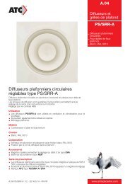
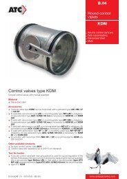
F. Unit circuit diagram<br />
2). Heat pump WITH auxiliary electric heater:<br />
WATER TEMP.SENSOR<br />
2<br />
OPERATION PANEL<br />
3<br />
COIL TEMP.SENSOR<br />
AMBIENT TEMP.SENSOR<br />
EXHAUST TEMP.SENSOR<br />
ELECTRIC HEATER PROTECTOR<br />
COMPRESSOR<br />
C<br />
PRESURE PROTECTOR<br />
YELLOW/GREEN<br />
S<br />
R<br />
4-WAY VALVE<br />
YELLOW/GREEN<br />
FAN MOTOR<br />
Comp<br />
Elect Valve Fan<br />
N<br />
L<br />
1 2<br />
ELECTRIC.HEATER<br />
L N<br />
YELLOW/GREEN<br />
YELLOW/GREEN<br />
POWER SUPPLY<br />
13