Untitled
Untitled
Untitled

Create successful ePaper yourself
Turn your PDF publications into a flip-book with our unique Google optimized e-Paper software.
Foreword<br />
Dear Customer<br />
These instructions are intended to help you properly carry out repairs on the electronically controlled diesel<br />
injection system described in this document.<br />
In writing these instructions, we have assumed that you have the necessary knowledge of control systems<br />
for working on and with the electronic diesel control.<br />
Best regards<br />
MAN Nutzfahrzeuge Aktiengesellschaft<br />
Nuremberg Plant<br />
Since our products are in continuous development, we reserve the right to make technical modifications.<br />
© 2002 MAN Nutzfahrzeuge Aktiengesellschaft<br />
Reprint, duplication or translation, as a whole or in part without the written approval of MAN is prohibited.<br />
MAN reserves all rights accorded by the relevant laws on copyright.<br />
MTDA Technical status: 02.2002 51.99598–8049<br />
1
Contents<br />
Safety information . . . . . . . . . . . . . . . . . . . . . . . . . . . . . . . . . . . . . . . . . . . . . . . . . . . . . . . . . . . . . . . . . . . . . . . . 4<br />
Electronic diesel control . . . . . . . . . . . . . . . . . . . . . . . . . . . . . . . . . . . . . . . . . . . . . . . . . . . . . . . . . . . . . . . . . . . 6<br />
System description . . . . . . . . . . . . . . . . . . . . . . . . . . . . . . . . . . . . . . . . . . . . . . . . . . . . . . . . . . . . . . . . . . . . . . . 7<br />
Component description . . . . . . . . . . . . . . . . . . . . . . . . . . . . . . . . . . . . . . . . . . . . . . . . . . . . . . . . . . . . . . . . . . . . 9<br />
Control unit plug connector . . . . . . . . . . . . . . . . . . . . . . . . . . . . . . . . . . . . . . . . . . . . . . . . . . . . . . . . . . . . . 9<br />
Injection pump . . . . . . . . . . . . . . . . . . . . . . . . . . . . . . . . . . . . . . . . . . . . . . . . . . . . . . . . . . . . . . . . . . . . . . . . 11<br />
Electromagnetic fuel-delivery regulator . . . . . . . . . . . . . . . . . . . . . . . . . . . . . . . . . . . . . . . . . . . . . . . . . . . 11<br />
Resistor bank . . . . . . . . . . . . . . . . . . . . . . . . . . . . . . . . . . . . . . . . . . . . . . . . . . . . . . . . . . . . . . . . . . . . . . . . . 12<br />
Electrohydraulic shut-off device EHAB . . . . . . . . . . . . . . . . . . . . . . . . . . . . . . . . . . . . . . . . . . . . . . . . . . . . 13<br />
Drive stage selection . . . . . . . . . . . . . . . . . . . . . . . . . . . . . . . . . . . . . . . . . . . . . . . . . . . . . . . . . . . . . . . . . . . 16<br />
Turbo air and coolant temperature sensors . . . . . . . . . . . . . . . . . . . . . . . . . . . . . . . . . . . . . . . . . . . . . . . . 17<br />
Turbo pressure sensor (51.27421–0181) . . . . . . . . . . . . . . . . . . . . . . . . . . . . . . . . . . . . . . . . . . . . . . . . . . 18<br />
RPM sensor . . . . . . . . . . . . . . . . . . . . . . . . . . . . . . . . . . . . . . . . . . . . . . . . . . . . . . . . . . . . . . . . . . . . . . . . . . 19<br />
Notes on operation . . . . . . . . . . . . . . . . . . . . . . . . . . . . . . . . . . . . . . . . . . . . . . . . . . . . . . . . . . . . . . . . . . . . . . . 20<br />
Self-diagnosis . . . . . . . . . . . . . . . . . . . . . . . . . . . . . . . . . . . . . . . . . . . . . . . . . . . . . . . . . . . . . . . . . . . . . . . . . . . . 21<br />
Flash code . . . . . . . . . . . . . . . . . . . . . . . . . . . . . . . . . . . . . . . . . . . . . . . . . . . . . . . . . . . . . . . . . . . . . . . . . . . 22<br />
List of checking procedures . . . . . . . . . . . . . . . . . . . . . . . . . . . . . . . . . . . . . . . . . . . . . . . . . . . . . . . . . . . . . . . . 24<br />
Troubleshooting chart . . . . . . . . . . . . . . . . . . . . . . . . . . . . . . . . . . . . . . . . . . . . . . . . . . . . . . . . . . . . . . . . . . . . . 27<br />
Troubleshooting program . . . . . . . . . . . . . . . . . . . . . . . . . . . . . . . . . . . . . . . . . . . . . . . . . . . . . . . . . . . . . . . . . . 30<br />
Test . . . . . . . . . . . . . . . . . . . . . . . . . . . . . . . . . . . . . . . . . . . . . . . . . . . . . . . . . . . . . . . . . . . . . . . . . . . . . . . . . . . . 31<br />
Drive stage selection . . . . . . . . . . . . . . . . . . . . . . . . . . . . . . . . . . . . . . . . . . . . . . . . . . . . . . . . . . . . . . . . . . . 31<br />
RPM sensor . . . . . . . . . . . . . . . . . . . . . . . . . . . . . . . . . . . . . . . . . . . . . . . . . . . . . . . . . . . . . . . . . . . . . . . . . . 32<br />
Boost pressure sensor . . . . . . . . . . . . . . . . . . . . . . . . . . . . . . . . . . . . . . . . . . . . . . . . . . . . . . . . . . . . . . . . . 33<br />
Control rod position sensor . . . . . . . . . . . . . . . . . . . . . . . . . . . . . . . . . . . . . . . . . . . . . . . . . . . . . . . . . . . . . 34<br />
Coolant temperature sensor . . . . . . . . . . . . . . . . . . . . . . . . . . . . . . . . . . . . . . . . . . . . . . . . . . . . . . . . . . . . . 35<br />
Resistor bank . . . . . . . . . . . . . . . . . . . . . . . . . . . . . . . . . . . . . . . . . . . . . . . . . . . . . . . . . . . . . . . . . . . . . . . . . 36<br />
Fuel volume regulator . . . . . . . . . . . . . . . . . . . . . . . . . . . . . . . . . . . . . . . . . . . . . . . . . . . . . . . . . . . . . . . . . . 37<br />
Auxiliary rpm sensor . . . . . . . . . . . . . . . . . . . . . . . . . . . . . . . . . . . . . . . . . . . . . . . . . . . . . . . . . . . . . . . . . . . 38<br />
Charge-air temperature sensor . . . . . . . . . . . . . . . . . . . . . . . . . . . . . . . . . . . . . . . . . . . . . . . . . . . . . . . . . . 39<br />
Undervoltage . . . . . . . . . . . . . . . . . . . . . . . . . . . . . . . . . . . . . . . . . . . . . . . . . . . . . . . . . . . . . . . . . . . . . . . . . 40<br />
Control unit . . . . . . . . . . . . . . . . . . . . . . . . . . . . . . . . . . . . . . . . . . . . . . . . . . . . . . . . . . . . . . . . . . . . . . . . . . . 41<br />
Engine overspeed . . . . . . . . . . . . . . . . . . . . . . . . . . . . . . . . . . . . . . . . . . . . . . . . . . . . . . . . . . . . . . . . . . . . . 42<br />
EDC control box for idle speed adjustment . . . . . . . . . . . . . . . . . . . . . . . . . . . . . . . . . . . . . . . . . . . . . . . . 43<br />
CAN system (control unit) . . . . . . . . . . . . . . . . . . . . . . . . . . . . . . . . . . . . . . . . . . . . . . . . . . . . . . . . . . . . . . 44<br />
Main relay . . . . . . . . . . . . . . . . . . . . . . . . . . . . . . . . . . . . . . . . . . . . . . . . . . . . . . . . . . . . . . . . . . . . . . . . . . . . 45<br />
Atmospheric pressure sensor (in control unit) . . . . . . . . . . . . . . . . . . . . . . . . . . . . . . . . . . . . . . . . . . . . . . 46<br />
CAN system (TSC1-FM message) . . . . . . . . . . . . . . . . . . . . . . . . . . . . . . . . . . . . . . . . . . . . . . . . . . . . . . . 47<br />
Control unit, EEPROM processor 1 fault . . . . . . . . . . . . . . . . . . . . . . . . . . . . . . . . . . . . . . . . . . . . . . . . . . 48<br />
Control unit, EEPROM processor 2 fault . . . . . . . . . . . . . . . . . . . . . . . . . . . . . . . . . . . . . . . . . . . . . . . . . 49<br />
Control unit (processor run-on) . . . . . . . . . . . . . . . . . . . . . . . . . . . . . . . . . . . . . . . . . . . . . . . . . . . . . . . . . . 50<br />
Control unit watchdog run-on fault . . . . . . . . . . . . . . . . . . . . . . . . . . . . . . . . . . . . . . . . . . . . . . . . . . . . . . . 51<br />
Control rod position sensor – loose contact . . . . . . . . . . . . . . . . . . . . . . . . . . . . . . . . . . . . . . . . . . . . . . . . 52<br />
PBM interface . . . . . . . . . . . . . . . . . . . . . . . . . . . . . . . . . . . . . . . . . . . . . . . . . . . . . . . . . . . . . . . . . . . . . . . . . 53<br />
Electrohydraulic shut-off device EHAB . . . . . . . . . . . . . . . . . . . . . . . . . . . . . . . . . . . . . . . . . . . . . . . . . . . . 54<br />
2
Contents<br />
Plug connections . . . . . . . . . . . . . . . . . . . . . . . . . . . . . . . . . . . . . . . . . . . . . . . . . . . . . . . . . . . . . . . . . . . . . . . . . 55<br />
Rating data sheet . . . . . . . . . . . . . . . . . . . . . . . . . . . . . . . . . . . . . . . . . . . . . . . . . . . . . . . . . . . . . . . . . . . . . . . . 57<br />
Revision list . . . . . . . . . . . . . . . . . . . . . . . . . . . . . . . . . . . . . . . . . . . . . . . . . . . . . . . . . . . . . . . . . . . . . . . . . . . 57<br />
Scope . . . . . . . . . . . . . . . . . . . . . . . . . . . . . . . . . . . . . . . . . . . . . . . . . . . . . . . . . . . . . . . . . . . . . . . . . . . . . . . . 57<br />
General features . . . . . . . . . . . . . . . . . . . . . . . . . . . . . . . . . . . . . . . . . . . . . . . . . . . . . . . . . . . . . . . . . . . . . . 57<br />
Temperature range . . . . . . . . . . . . . . . . . . . . . . . . . . . . . . . . . . . . . . . . . . . . . . . . . . . . . . . . . . . . . . . . . . . . 58<br />
Mechanical characteristics . . . . . . . . . . . . . . . . . . . . . . . . . . . . . . . . . . . . . . . . . . . . . . . . . . . . . . . . . . . . . . 59<br />
Electrical ratings . . . . . . . . . . . . . . . . . . . . . . . . . . . . . . . . . . . . . . . . . . . . . . . . . . . . . . . . . . . . . . . . . . . . . . . 60<br />
Immunity to interference . . . . . . . . . . . . . . . . . . . . . . . . . . . . . . . . . . . . . . . . . . . . . . . . . . . . . . . . . . . . . . . . 61<br />
Resistance to motor vehicle-specific liquids / fluids . . . . . . . . . . . . . . . . . . . . . . . . . . . . . . . . . . . . . . . . . 62<br />
Mechanical test data . . . . . . . . . . . . . . . . . . . . . . . . . . . . . . . . . . . . . . . . . . . . . . . . . . . . . . . . . . . . . . . . . . . 62<br />
Service life test . . . . . . . . . . . . . . . . . . . . . . . . . . . . . . . . . . . . . . . . . . . . . . . . . . . . . . . . . . . . . . . . . . . . . . . . 62<br />
Connection diagram . . . . . . . . . . . . . . . . . . . . . . . . . . . . . . . . . . . . . . . . . . . . . . . . . . . . . . . . . . . . . . . . . . . . . . 63<br />
Index . . . . . . . . . . . . . . . . . . . . . . . . . . . . . . . . . . . . . . . . . . . . . . . . . . . . . . . . . . . . . . . . . . . . . . . . . . . . . . . . . . . 66<br />
3
Safety information<br />
General<br />
Important safety regulations are summarized in this quick-reference overview and arranged by topic to effectively<br />
convey the knowledge necessary to avoid accidents causing injury, damage or environmental hazard.<br />
The engine operating manual contains further information.<br />
Important:<br />
Should an accident occur despite all precautionary measures, particularly one involving contact with corrosive<br />
acid, penetration of fuel under the skin, scalding by hot oil, antifreeze splashing into the eyes etc. you<br />
must seek medical assistance immediately.<br />
1. Instructions for avoiding accidents likely to cause injury<br />
Only authorized and qualified personnel are permitted to carry out inspection, adjustment and repair<br />
work<br />
D<br />
Secure and chock vehicles to prevent the vehicle rolling<br />
D<br />
D<br />
D<br />
Firmly secure units and assemblies on disassembly<br />
Only authorized personnel are permitted to start and operate the engine<br />
Do not stand too close to rotating parts while the engine is running<br />
Wear close-fitting working clothes<br />
D<br />
Do not touch a hot engine with bare hands:<br />
Risk of burns<br />
D<br />
Keep area surrounding engine, ladders and stairways free of oil and grease.<br />
Accidents caused by slipping can have serious consequences<br />
ËË<br />
D<br />
D<br />
Only work with tools which are in good condition. Damaged or worn spanners and<br />
wrenches can slip off: Risk of injury<br />
Persons must not stand under an engine suspended on a crane hook. Keep lifting<br />
gear in perfect condition<br />
D<br />
Only open coolant circuit once the engine has cooled down. Follow the instructions<br />
given under “Care and Maintenance” in the Operating Manual exactly if it is not possible<br />
to avoid opening the coolant circuit with the engine at operating temperature<br />
4
Safety information<br />
D<br />
Do not tighten or loosen pipes and hoses that are under pressure (lubricant circuit,<br />
coolant circuit and any downstream hydraulic oil circuits): Risk of injury caused by<br />
liquids escaping under pressure<br />
D<br />
D<br />
D<br />
D<br />
D<br />
Do not place hands under the fuel jet when checking injection nozzles.<br />
Do not inhale fuel mist<br />
Always disconnect battery when working on the electrical system<br />
Do not use rapid charger to start the engine. Rapid charging of batteries is only permitted<br />
with the positive and negative leads disconnected!<br />
Disconnect batteries only with the ignition turned off<br />
Observe manufacturer’s instructions for handling batteries.<br />
Caution:<br />
Battery acid is toxic and corrosive. Battery gasses are explosive<br />
D<br />
D<br />
Only use suitable measuring instruments to measure voltages! The minimum input<br />
resistance of a measuring instrument should be 10 MΩ<br />
Only disconnect or connect wiring harness connectors on electronic control units with<br />
the ignition turned off!<br />
Disconnect batteries and connect the positive lead to the negative lead such that they are<br />
electrically conductive before carrying out any electric welding work. Earth the welding set<br />
as close to the weld as possible. Do not place cables of welding set parallel to electrical<br />
lines in the vehicle.<br />
Refer to the “Welders Code of Practice” for further accident prevention measures.<br />
D<br />
When carrying out repaint jobs, electronic components may be subject to high temperatures<br />
(max. 95°C) for only very short periods; a period of up to approx. 2 hours is<br />
permissible at a max. temperature of 85°C, disconnect batteries<br />
Limitation of liability for parts and accessories<br />
In your own interest, we strongly recommend you use only accessories and original MAN parts expressly<br />
approved by MAN for your MAN engine. The reliability, safety and suitability of these parts and accessories<br />
have been tested specially for MAN engines. Despite us keeping a constant eye on the market, we cannot<br />
assess and be held responsible for these properties in other products, even if they bear TÜV (German testing<br />
and inspection institute) approval or any other official approval in any particular case.<br />
Laying up or storage<br />
Special measures must be implemented in accordance with MAN Company Standard M 3069 Part 3 if engines<br />
are to be laid up or placed into storage for more than 3 months.<br />
5
Electronic diesel control<br />
Electronic diesel control EDC<br />
General<br />
The requirements set by customers and legislation in respect of fuel consumption, exhaust emission and<br />
noise characteristics etc. on diesel engines have grown over the years and will be even more stringent in<br />
the future.<br />
The fact that conventional mechanical injection systems have reached their performance limits has made<br />
electronically controlled fuel injection systems necessary.<br />
Such systems increase engine efficiency, improve driving comfort and lessen the burden on the environment.<br />
EDC (Electronic Diesel Control) meets these requirements.<br />
6
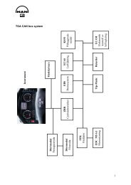
System description<br />
System description EDC M(S) 5<br />
Engine<br />
speed 1<br />
Engine<br />
speed 2<br />
Drive stage<br />
selection<br />
Boost<br />
pressure<br />
Charge air intake<br />
temperature<br />
Coolant<br />
temperature<br />
EHAB<br />
Electrohydraulic cut-out<br />
Control unit<br />
Intermediate<br />
engine speeds<br />
Power supply<br />
terminal 30<br />
Terminal 15<br />
PWM signal<br />
ISO diagnosis<br />
Diagnosis<br />
request<br />
Diagnosis<br />
warning lamp<br />
CAN bus<br />
Engine speed<br />
The controller contains<br />
– the linear solenoid<br />
– the control rod position transducer<br />
The linear solenoid is actuated by the electronic control unit. The control unit processes information which it<br />
receives via<br />
– the control rod position transducer<br />
– the drive position selection<br />
– drive stage selection<br />
– coolant temperature sensor<br />
– charge-air temperature sensor<br />
– intermediate engine speed setpoint<br />
– and the rpm sensors.<br />
The diagnosis request push button and the EDC indicator lamp are used in detecting faults and signalling<br />
them through a code.<br />
An ISO interface provides a communication with the MAN-cats test and diagnostic computer.<br />
The control unit, with its program adapted to the engine model concerned, determines the optimum setting<br />
of the control rod from all the measured values.<br />
To ensure the vehicle can still be driven to the nearest workshop in the event of one or several sensors failing,<br />
an emergency drive function is integrated in the control unit which, depending on the situation, makes it<br />
possible to continue driving with restricted functions.<br />
When the brakes are applied, the system operates as an intermediate engine speed controller with a cyclic<br />
irregularity (P-degree) of 0, i.e. a set intermediate engine speed is maintained exactly provided the engine<br />
develops sufficient power output for this purpose.<br />
7
System description<br />
The idle speed control operates in the same way as the intermediate engine speed control. The idle speed<br />
is exactly maintained by means of the idle speed governor as long as the engine output is sufficient for this.<br />
The regulated idle speed can be varied within certain limits.<br />
Starting-fuel delivery is output when either a lower start recognition speed is exceeded. The starting fuel<br />
volume and cold idle speed are limited as a function of the coolant temperature to avoid impermissible<br />
smoke emission and unnecessary revving of the engine after starting.<br />
8
Component description<br />
Control unit plug connector<br />
Pin arrangement<br />
19 . . . . . . . . . . . . . . . . . . . . . . . 1<br />
37 . . . . . . . . . . . . . . . . . . . . . . 20<br />
55 . . . . . . . . . . . . . . . . . . . . . . 38<br />
Pin assignments of control unit plug connector<br />
EDC Pin Connection to component (O=Output, I=Input)<br />
1 Injection pump controller pin 8 O<br />
Jumper to pin 2 (activation of fuel volume regulator) O<br />
2 Jumper to pin 1 (activation of fuel-delivery regulator) O<br />
3 Not used<br />
4 Not used<br />
5 Not used<br />
6 Not used<br />
7 Not used<br />
8 Not used<br />
9 Injection pump controller pin 5 (control rod position sensor, instrument coil)<br />
10 Injection pump controller pin 1 (control rod position sensor, reference coil)<br />
11 Injection pump controller pin 6 (control rod position sensor, centre pick-off)<br />
12 Not used<br />
13 Negative from control unit for (Sensor ground)<br />
– rpm sensor<br />
– turbo pressure sensor<br />
– drive stage selection<br />
– turbo air temperature sensor<br />
– coolant temperature sensor<br />
– resistor bank<br />
14 Electrohydraulic shut-off valve (EHAB) O<br />
15 Control unit power supply battery + (via main relay and fuse) I<br />
16 Control unit power supply battery + (via main relay and fuse) I<br />
17 Ground for auxiliary rpm sensor<br />
18 Power supply battery –<br />
19 Power supply battery –<br />
20 EDC indicator lamp and diagnostic lamp O<br />
21 RPM sensor (twisted with cable pin 13) I<br />
22 Auxiliary rpm sensor (twisted with cable pin 17) I<br />
23 Intermediate engine speed control ZDR 1 I<br />
24 Not used<br />
25 Not used<br />
9
Component description<br />
EDC Pin Connection to component (O=Output, I=Input)<br />
26 Not used<br />
27 Drive stage selection (signal) I<br />
28 Engine speed signal output from control unit (square-wave pulses) O<br />
29 Multiplex signal O<br />
30 CAN-L<br />
31 CAN-H<br />
32 Not used<br />
33 Turbo pressure sensor (supply) O<br />
34 Turbo air temperature sensor I<br />
35 Resistor bank<br />
36 Turbo pressure sensor (signal) I<br />
37 Not used<br />
38 Not used<br />
39 Empty fuel switch signal<br />
40 External engine cut-out<br />
41 Intermediate engine speed control ZDR 2 I<br />
42 Not used<br />
43 Not used<br />
44 Speed control device I<br />
45 Drive stage selection (supply)<br />
46 Relay power supply batt.+ (main relay) O<br />
47 Relay power supply n/o contact I<br />
48 Diagnostic connection (K-link)<br />
49 Diagnostic connection (L-link)<br />
50 Not used<br />
51 Resistor bank 3 kΩ<br />
52 Assigned to batt.+ (to enable multiplex signal) I<br />
53 Coolant temperature sensor I<br />
54 Not used<br />
55 Not used<br />
10
Component description<br />
Injection pump<br />
The EDC injection pump consists of a heavy-duty version of a conventional injection stage of the wellknown<br />
Bosch P-pumps and, instead of the mechanical regulator, a flange-mounted electromagnetic fueldelivery<br />
regulator with a control rod position transducer.<br />
Electromagnetic fuel-delivery regulator<br />
Description:<br />
The fuel-delivery regulator operates in conjunction with the P-pump. The most important component of the<br />
fuel-delivery regulator is a linear solenoid whose armature acts directly on the control rod thus determining<br />
the injection volume by means of the control position. When no power is applied, the control rod is held in<br />
the stop position by means of a spring.<br />
The other important component in the regulator is a control rod position sensor.<br />
Injection pump Control rod Control rod position sensor<br />
Fuel delivery regulator<br />
(linear solenoid)<br />
Fuel-delivery regulator<br />
6<br />
7<br />
5<br />
2<br />
1<br />
4<br />
3<br />
Control rod position sensor<br />
Plug connection<br />
11
Component description<br />
Resistor bank<br />
On commercial vehicles, certain items of data are fed to the EDC which are not required for railway operation.<br />
An example of such data is a signal from the tachograph (speedometer, tachograph) which is used for controlling<br />
or limiting the driving speed (see Page 36).<br />
Some unused EDC connections must be closed by resistors since the EDC constantly conducts a signalrange<br />
check, as described on Page 21.<br />
Interior circuit<br />
3<br />
2<br />
1<br />
6<br />
5<br />
4<br />
R1 0.511 kOhm<br />
R5 0.511 kOhm<br />
R2 1.37 kOhm<br />
R6 1.37 kOhm<br />
R7 3.08 kOhm<br />
R3 3.08 kOhm<br />
R8 8.20 kOhm<br />
R4 8.20 kOhm<br />
9<br />
8<br />
7<br />
2 8 4 3 5 7 6 9 1<br />
12
Component description<br />
Electrohydraulic shut-off device EHAB<br />
The EHAB (electrohydraulic shut-off device) is a safety-relevant component.<br />
The EHAB shuts off the fuel supply to the injection pump in the event of certain faults occurring in the EDC<br />
system. The EHAB is connected into the fuel supply system between the delivery pump and pump suction<br />
chamber. The EHAB reverses the delivery direction of the delivery pump so that the pressure in the suction<br />
chamber is reduced rapidly thus interrupting the filling procedure.<br />
Power is always applied to the EHAB during operation. The power circuit is interrupted by the EDC control<br />
unit in order to activate the EHAB (e.g. for emergency engine shut-down).<br />
For this reason, the ignition must be turned on when bleeding the fuel system by means of the presupply<br />
pump.<br />
2 1<br />
T<br />
ÜV<br />
Fi<br />
FP<br />
4 3<br />
5 6<br />
2<br />
1<br />
Plug connection<br />
13
Component description<br />
Fuel circuit diagram – Engine running<br />
Injection pump<br />
6 Suction<br />
6<br />
chamber<br />
Pressure chamber<br />
Flame starting<br />
system<br />
11 11<br />
3<br />
T<br />
UV<br />
Injection nozzles<br />
Fi<br />
Fp<br />
10<br />
4 4<br />
9 9 9 9<br />
7<br />
Engine<br />
5<br />
13<br />
M<br />
8<br />
12<br />
2<br />
1<br />
1 Fuel tank 7 Overflow valve 3.7–4.3 bar<br />
2 Prefilter 8 Pre-delivery pump (hand primer)<br />
3 Electrohydraulic shut-off device (EHAB) 9 Fuel hose NW12<br />
(overrevving protection) 10 Magneto valve<br />
4 Delivery pump (double acting) 11 Flame heater plugs<br />
5 Fuel filter 12 Electric fuel pump<br />
6 Overflow valve 2.0–2.5 bar 13 Overflow valve 1.0 bar<br />
Caution:<br />
Presupply pump integration in the fuel circuit should be checked according to pump type.<br />
14
Component description<br />
Fuel circuit diagram – engine shutoff using EHAB<br />
Injection pump<br />
6<br />
Suction<br />
chamber<br />
6<br />
Pressure chamber<br />
Flame starting<br />
system<br />
11 11<br />
3<br />
T<br />
UV<br />
Injection nozzles<br />
Fi<br />
Fp<br />
10<br />
4 4<br />
7<br />
9 9 9 9<br />
Engine<br />
5<br />
13<br />
M<br />
12<br />
8 2<br />
1<br />
1 Fuel tank 7 Overflow valve 3.7–4.3 bar<br />
2 Prefilter 8 Pre-delivery pump (hand primer)<br />
3 Electrohydraulic shut-off device (EHAB) 9 Fuel hose NW12<br />
(overrevving protection) 10 Magneto valve<br />
4 Delivery pump (double-acting) 11 Flame heater plug<br />
5 Fuel filter 12 Electric fuel pump<br />
6 Overflow valve 2.0–2.5 bar 13 Overflow valve 1.0 bar<br />
Caution:<br />
Presupply pump integration in the fuel circuit should be checked according to pump type.<br />
15
Component description<br />
Drive stage selection<br />
Function<br />
The drive stage selection device transfers driver’s requests in the form of voltages to the control unit.<br />
The control unit then derives the corresponding engine speed or volumetric charge from these voltages.<br />
Block diagram<br />
Pin 13<br />
Pin 39<br />
Pin 13<br />
Pin 27<br />
Pin 45<br />
U = Reference voltage, approx. 5 V from the EDC control unit<br />
u = Setpoint<br />
Pedal travel sensor simulation values<br />
Lower idle speed: 257–539 mV / upper idle speed: 2944–4501 mV<br />
Empty fuel switch: switch-on point at 569–976 mV (typically 800 mV)<br />
top idle<br />
speed<br />
lower idle<br />
speed<br />
257 mV 976 mV 2944 mV 4501 mV [ mV ]<br />
539 mV 569 mV Fault registration<br />
Empty fuel switch range<br />
(typically 880 mV)<br />
Exceptionally, the voltage “u” is produced electronically as drive position selection, or the setpoint selection<br />
(drive position selection) takes place via the CAN bus.<br />
16
Component description<br />
Turbo air B197 (51.27421–0165)<br />
Characteristic R=f (-í)<br />
Turbo air and coolant temperature sensors<br />
4<br />
2<br />
3<br />
1<br />
Plug connection<br />
Coolant B124 (51.27421–0172)<br />
Characteristic R=f (-í)<br />
4<br />
1<br />
2<br />
3<br />
Plug connection<br />
Function<br />
The turbo air and coolant temperature sensors are NTC resistors. The coolant temperature sensor is located<br />
in the coolant circuit and the turbo air temperature sensor in the turbo air circuit after the intercooler.<br />
They supply the control unit with information relating to the coolant and turbo air temperature.<br />
17
Component description<br />
Turbo pressure sensor (51.27421–0181)<br />
1 4<br />
Output<br />
Ground – Supply +<br />
2 3<br />
Plug connection<br />
Function<br />
The pressure sensor element consists of an Si diaphragm which contains several piezo-resistive (pressuresensitive)<br />
semiconductor resistors. The pressure to be measured “deflects” the sprung diaphragms. As a<br />
result, extended or compressed zones are created on the surface of the diaphragms. The action of these<br />
forces changes the electrical ratings of semiconductor resistor arrays arranged in these zones. These values<br />
are a measure for the pressure to be measured.<br />
Circuit diagram<br />
Output +5 V<br />
Pin 13 36 33<br />
Pressure<br />
connection<br />
18
Component description<br />
RPM sensor<br />
Housing: grey<br />
Coding A<br />
2<br />
1<br />
2 1<br />
Housing: black<br />
Coding B<br />
Plug connection<br />
RPM sensor (1)<br />
Plug connection<br />
Auxiliary rpm sensor (2)<br />
Function<br />
The rpm sensor consists of a permanent magnet and a coil with a high number of windings. The magnet<br />
“touches” the rotaring component to be measured, normally a crown gear or grooved ring gear, with its<br />
magnetic field.<br />
With the EDC M(S) 5 system, there are 6 grooves on the flywheel.<br />
When a groove passes the sensor, the magnetic current is reduced. This generates an induction voltage in<br />
the sensor coil which is measured by the electronic control. The distance between the sensor and the<br />
grooved ring gear is approx. 1 mm.<br />
Two rpm sensors are required to ensure reliable operation of the EDC system.<br />
Both rpm sensors are installed in the flywheel housing.<br />
A distinction is made between the rpm sensor and the auxiliary rpm sensor.<br />
The rpm sensor is installed in the flywheel housing such that an rpm pulse is triggered 10° after TDC.<br />
The auxiliary rpm sensor is installed in the flywheel housing in such a way that an auxiliary speed pulse is<br />
triggered 18° after TDC. The signals of the auxiliary rpm sensor are used only for redundant engine speed<br />
sensing.<br />
Caution:<br />
Do not confuse installation locations of the rpm sensor (1) and the auxiliary rpm sensor (2), nor the “+”<br />
and “–” wires of the sensors.<br />
19
Notes on operation<br />
Start procedure<br />
The gear stage must be selected (idle speed request setpoint specification) to start the engine.<br />
Changing idle speed<br />
Idle speed setting is possible using EOL programming (MAN Cats), but this should only be performed by<br />
MAN customer service personnel.<br />
Intermediate engine speed control<br />
Different intermediate engine speeds can be programmed by means of MAN-Cats:<br />
D ZDR 1, ZDR 2 and ZDR 3<br />
These intermediate engine speeds are set by corresponding pin connection.<br />
The intermediate engine speeds can be changed using EOL programming (MAN-Cats), but this should only<br />
be performed by MAN customer service personnel.<br />
20
Self-diagnosis<br />
General<br />
The EDC system continuously checks itself by means of a signal-range check. It does this by running a<br />
signal-range check. During this check, all signals are scanned for presence and plausibility within a certain<br />
time frame (determined by the software).<br />
The control unit itself is also constantly checked the whole time the program is running. The first check is<br />
always carried out when the ignition is turned on.<br />
Any faults occurring during operation are stored for the purpose of subsequent diagnosis.<br />
A maximum of 5 faults can be stored simultaneously in the fault memory. The faults are stored in the order<br />
in which they occurred. If more than 5 faults occur, the least significant fault is deleted.<br />
Fault storage includes<br />
D allocation of fault priority,<br />
D identification of the type of fault,<br />
D recording of fault frequency.<br />
Sporadic faults are recorded by a frequency counter the first time they occur. This means that a certain frequency<br />
number is set which is decremented by one during every start procedure. If the fault no longer occurs,<br />
it is deleted when the counter reaches zero.<br />
To report the fault, the diagnostic lamp either comes on permanently or remains off, depending on the significance<br />
of the fault. If several faults are stored, the steady light has priority over OFF.<br />
Only faults currently present are indicated. Faults which are stored but which are not currently present are<br />
not indicated.<br />
There are two fault memories:<br />
D<br />
D<br />
Fault memory for diagnosis via ISO interface. This memory can be read out and cleared with MAN-Cats<br />
Fault memory for diagnosis via flash code. The flash code memory can be read out and cleared with the<br />
aid of the diagnosis button<br />
Faults are always entered in both fault memories simultaneously and can be read out even after the ignition<br />
has been switched off and back on again.<br />
Indicator lamp check:<br />
The EDC indicator lamp lights as a lamp test for approximately 2 seconds after the ignition is switched on.<br />
21
Self-diagnosis<br />
The following measures are implemented automatically depending on the significance<br />
of the fault:<br />
D Changeover to suitable substitute function to enable continued yet restricted operation<br />
D Reduction of engine speed to idle speed (drive stage 0)<br />
D Immediate shut-down of the engine if required for safety reasons. Depending on the type of fault, engine<br />
shut-down is done by reducing the fuel delivery volume to zero or by way of an emergency shut-down<br />
with EHAB<br />
Flash code<br />
To read out the fault memory<br />
D With the engine stationary or running and the “ignition” switched on, press and hold the diagnosis request<br />
button for at least 2 seconds. The diagnosis lamp will not come on<br />
D The flash procedure starts after a pause of approximately 3 seconds. The flash code is divided into long<br />
and short pulses<br />
D The diagnostic system always outputs only one fault at a time. In order to check whether several faults<br />
are stored, the fault scanning procedure must be repeated until the fault that was shown first reappears<br />
20<br />
18/19<br />
49<br />
Example of a flash code output<br />
On<br />
Lamp<br />
Off<br />
0.5 sec<br />
Fault 2x long, 5x short<br />
OFF phase before output:<br />
ON duration of a long pulse:<br />
OFF phase between two long pulses:<br />
OFF phase between a long and short pulse:<br />
ON duration of a short pulse:<br />
OFF phase between two short pulses:<br />
3 seconds.<br />
2 seconds.<br />
1 second.<br />
5 seconds.<br />
0.5 seconds.<br />
0.5 seconds.<br />
To clear fault memory<br />
1. Press request button<br />
2. Switch on ignition<br />
3. Press and hold request button for a further 3 seconds but not longer than 10 seconds<br />
22
Self-diagnosis<br />
Fault code output MAN M(S) 5 EDC / MS 5 EDC<br />
Number of<br />
flashes<br />
Long<br />
Short<br />
Overview of flash codes<br />
Fault path<br />
Steady<br />
light fault<br />
Maintained<br />
light<br />
Reset<br />
a) / b)<br />
0 0 No fault stored<br />
1 Drive stage selection yes b) 31<br />
4 Engine speed sensing (rpm sensor) yes b) 32<br />
5 Turbo pressure sensing yes b) 33<br />
6 Control rod position sensing yes a) 34<br />
7 Coolant temperature sensing yes b) 35<br />
8 Resistor bank no b) 36<br />
10 Fuel volume regulator monitoring yes a) 37<br />
14 Engine speed sensing (auxiliary rpm sensor) yes b) 38<br />
1 1 Turbo air temperature sensing yes b) 39<br />
1 3 Battery voltage sensing no – 40<br />
1 6 Processor coupling defective yes a) 41<br />
1 7 Overrevving yes b) 42<br />
1 12 Resistor bank yes a) 36<br />
1 13 Control box no b) 43<br />
1 15 CAN system yes b) 44<br />
2 5 Main relay sticking no – 45<br />
2 8 Atmospheric pressure sensing yes b) 46<br />
2 13 TSC1-FM (setpoint selection) yes b) 47<br />
3 2 EEPROM processor 1 error yes a) 48<br />
3 3 EEPROM processor 2 error yes a) 49<br />
3 8 Afterrunning not completed no – 50<br />
3 9 Afterrunning watchdog error no b) 51<br />
3 10 Control rod position sensor – loose contact no – 52<br />
– – PBM interface no – 53<br />
– – Redundant cut-out device (EHAB) no – 54<br />
see<br />
page<br />
a) Reset by “Ignition” Off / On (cold restart)<br />
b) Reset takes place automatically once the fault is rectified<br />
23
List of checking procedures<br />
List of checking procedures EDC MS 5<br />
1. Resistance checks<br />
– “Ignition” off, control unit not connected<br />
– Engine temperature [25°C<br />
– Socket box connected<br />
– Measure resistance between PIN+ and PIN– with multimeter<br />
PIN+ PIN– Set-point value Measured value<br />
Control rod position sensor 11 9 18–25 Ohms . . . . . . . . . . . . . . . Ohms<br />
11 10 18–25 Ohms . . . . . . . . . . . . . . . Ohms<br />
18 9 >10 MOhms . . . . . . . . . . . . . . . MOhms<br />
18 10 >10 MOhms . . . . . . . . . . . . . . . MOhms<br />
RPM sensor (DZG) 21 13 0.8–1.0 kOhm . . . . . . . . . . . . . . . kOhms<br />
Auxiliary rpm sensor (HZG) 22 17 0.8–1.0 kOhm . . . . . . . . . . . . . . . kOhms<br />
Fuel-delivery regulator 15 1 0.7–1.3 Ohms . . . . . . . . . . . . . . . Ohms<br />
18 1 >10 MOhms . . . . . . . . . . . . . . . MOhms<br />
16 2 0.7–1.3 Ohms . . . . . . . . . . . . . . . Ohms<br />
Ground 13 18 >10 MOhms . . . . . . . . . . . . . . . MOhms<br />
17 19 >10 MOhms . . . . . . . . . . . . . . . MOhms<br />
EHAB 14 18/19 30–70 Ohms . . . . . . . . . . . . . . . Ohms<br />
Coolant temperature sensor 53 13 1.3–3.6 kOhms 1) . . . . . . . . . . . . . . . kOhms<br />
Charge-air temperature sensor 34 13 1.3–3.6 kOhms . . . . . . . . . . . . . . . kOhms<br />
Boost pressure sensor 33, 36 13 Resistance measurement not appropriate<br />
Resistor bank 35 13 500–520 Ohms . . . . . . . . . . . . . . . Ohms<br />
51 13 2.8–3.2 kOhms . . . . . . . . . . . . . . . kOhms<br />
1) Resistance approximately 230–460 W with engine at operating temperature (approximately 80°C)<br />
24
List of checking procedures<br />
2. Test for engine when running and vehicle stationary (gearbox neutral)<br />
– Engine temperature approx. 30°C<br />
– Control unit connected<br />
– Corrective measures<br />
Set-point value Measured value Remark MAN-Cats<br />
RPM sensor (DZG) n-lower idle speed n= ................ rpm Min (low. idle sp.) Engine speed<br />
n-top idle speed n= ................ rpm Max (top idle sp.) (Monitoring 2)<br />
Auxiliary rpm sensor (HZG)<br />
n-lower idle speed n= ................ rpm Min (low. idle sp.) Engine speed<br />
n-top idle speed n= ................ rpm Max (top idle sp.) (Monitoring 2)<br />
– Measure voltage between PIN+ and PIN– with multimeter<br />
Control unit supply<br />
(U-Batt)<br />
Reference voltage<br />
(Uref)<br />
Idle speed switch<br />
(LGS, NO contact)<br />
Charge-air temperature<br />
sensor (LTF)<br />
Water temperature sensor<br />
(WTF)<br />
Boost pressure sensor<br />
(LDF)<br />
PIN<br />
+<br />
15<br />
47<br />
45<br />
33<br />
Resistor bank 35<br />
51<br />
PIN<br />
–<br />
18<br />
19<br />
13<br />
13<br />
Set-point<br />
value [V]<br />
U-Batt<br />
U-Batt<br />
4.75–5.25<br />
4.75–5.25<br />
39 13 4.75–5.25<br />
0–2.00<br />
Measured<br />
value [V]<br />
. . . . . . . . .<br />
. . . . . . . . .<br />
. . . . . . . . .<br />
. . . . . . . . .<br />
. . . . . . . . .<br />
. . . . . . . . .<br />
Remark<br />
Throttle lever min.<br />
Throttle lever max.<br />
Engine<br />
speed<br />
Idle speed<br />
Idle speed<br />
idle speed<br />
Top idle sp.<br />
MAN-Cats<br />
(Monitoring)<br />
open<br />
closed<br />
34 13 4.17–2.62 . . . . . . . . . 10–50°C Idle speed 10–50°C<br />
53 13 3.46–1.22 . . . . . . . . . 30–90°C Idle speed 30–90°C<br />
36 13 0.94–1.20<br />
1.10–1.70<br />
13<br />
13<br />
0.75–1.25<br />
> 0.6<br />
. . . . . . . . .<br />
. . . . . . . . .<br />
. . . . . . . . .<br />
. . . . . . . . .<br />
Throttle lever min.<br />
Throttle lever max.<br />
Pos 0<br />
idle speed<br />
Top idle sp.<br />
Idle speed<br />
0–100 mbar<br />
300–600 mbar<br />
– Check main relay<br />
PIN+ PIN– Set-point value<br />
[V]<br />
Measured value [V]<br />
Remark<br />
Main relay * 47 18 U-Batt . . . . . . . . . . . . . . Ignition on<br />
0V . . . . . . . . . . . . . . Ignition off<br />
46 18<br />
0V . . . . . . . . . . . . . . Ignition on<br />
U-Batt . . . . . . . . . . . . . . Ignition off<br />
* Pin 46 must switch to U-Batt within 0.5 to 5 seconds after ignition has been switched off.<br />
25
List of checking procedures<br />
3. Flash code diagnosis check<br />
– EDC control unit connected<br />
– Socket box connected<br />
– Engine running<br />
Check procedure<br />
– Short-circuit rpm sensor; connect pin 21 to pin 13 to do this<br />
– Diagnosis lamp lights up<br />
– Engine speed is measured by auxiliary rpm sensor<br />
– Disconnect connection between pin 21 and pin 13<br />
– Press diagnosis button for at least 3 seconds but no more than 10 seconds<br />
– Check flash code (4x short = rpm sensor)<br />
– Deleting the fault memory; do this by turning off ignition pressing diagnosis button, turning on ignition,<br />
pressing and holding button for at least 3 seconds but not longer than 10 seconds<br />
4. EHAB check<br />
– Control unit connected<br />
– Socket box connected<br />
– Engine running<br />
Check procedure<br />
– Disconnect pin 14<br />
– Engine should shut down after no more than 10 seconds<br />
5. Capacitance reserve check<br />
The power capacitance of the line leading to the control rod position transducer must not exceed the specified<br />
maximum capacitance. The capacitance increases if the line is dirty or moist. This check is designed to<br />
establish how much capacitance reserve is still available.<br />
– Control unit connected<br />
– Socket box connected<br />
Check procedure<br />
– Connect capacitance decade between pin 11 and pin 13<br />
– Connect additional capacitance until the engine no longer starts<br />
– Record value<br />
Setpoint:<br />
>400 pF without wiring harness adapter (capacitance of wiring harness adapter approx. 100 pF),<br />
(wiring harness dry at approx. 25_C)<br />
– Deleting the fault memory<br />
After the checks have been completed, the fault memory must be cleared with MAN-Cats.<br />
No fault must be stored when the “ignition” is turned on again. If this is not the case, the fault must<br />
be located and eliminated in accordance with the troubleshooting procedure.<br />
26
Troubleshooting chart<br />
1. EDC self-diagnosis or flash code output<br />
2. Starter turns over engine only slowly or not at all<br />
3. Starter turns, engine does not start, engine does not start / difficult to start when cold<br />
4. Engine stalls (dies) during operation, no longer starts (starter turns), engine does not start / starts with difficulty when hot<br />
5. Sudden, temporary engine shut-down, engine does not reach full revs<br />
6. Engine only runs at idle speed, no throttle response<br />
7. Engine only runs at increased idle speed, no throttle response<br />
8. Rated engine speed distinctly reduced (even under no load)<br />
9. Reduced output in all ranges<br />
10. Irregular engine operation, traction loss<br />
11. Unstable idle speed, engine hunting, misfiring, knocking in engine<br />
12. Engine judder<br />
13. Unusual combustion noise<br />
14. Excessive smoke emission: White smoke / blue smoke<br />
15. Excessive smoke emission: Black smoke<br />
16. Engine temperature too high (coolant loss)<br />
17. Intermediate engine speed control cannot be activated / does not switch off,<br />
engine revs too high<br />
18. Fuel consumption too high<br />
19. Lubricating oil pressure too low<br />
20. Lubricating oil pressure too high<br />
21. Lubricating oil consumption too high<br />
22. Engine too loud / mechanical noise<br />
Possible causes<br />
x x<br />
Batteries discharged, battery lead connections loose or corroded, break in power<br />
circuit<br />
x<br />
Crank gear blocked<br />
x x<br />
Starter solenoid switch sticks (clicks) / defective, cable connection loose or damaged<br />
x x<br />
Starter / starter interlock relay defective (carbon brushes worked loose / worn,<br />
winding defective, short to ground)<br />
x x x x Engine oil viscosity unsuitable, not suitable for ambient temperature, lubricating<br />
oil quality does not correspond to specifications<br />
x x Oil level in sump too high<br />
x Oil level in sump too low, oil in sump too thin (mixed with condensate or fuel)<br />
x Engine temperature too high<br />
x Oil filter clogged<br />
x x Oil pressure gauge faulty<br />
x Safety valve in oil circuit defective (does not close, spring fatigued or broken)<br />
x x Bearing wear<br />
x Oil pump gears worn<br />
x Crankshaft timing gears worn, tooth flank backlash too great<br />
x x x Engine cold<br />
x<br />
Lubricating oil entering combustion chamber (piston rings worn, piston rings<br />
broken) – valve stem guide worn – overpressure in crankcase (crankcase vent<br />
clogged)<br />
x Relief valve in oil circuit faulty (does not open), oil lines / oil galleries clogged<br />
x Leaks in lubricating oil circuit, particularly at turbocharger and oil cooler<br />
x x Piston rings heavily worn, broken<br />
x<br />
x Piston pin or crankshaft bearing worn<br />
x Valve stems worn<br />
x x x Valve clearance not correct<br />
x x Valves jam<br />
x x x x Compression deficient, or more than 3–4 bar pressure difference between individual<br />
cylinders<br />
x x x Valve seats leaking<br />
o x x Increased power consumption due to faulty secondary consumers such as hydraulic<br />
pumps, fan, etc, power take-off engaged<br />
x x x x x Air cleaner soiled or clogged, charge-air system leaking, air inlet / exhaust lines<br />
clogged / leaking<br />
x x x x x x x x x Fuel low pressure system: fuel tank, prefilter, water trap faulty / clogged / mould /<br />
fungal attack, fuel unsuitable / heavily contaminated (paraffin added)<br />
x = Probable<br />
o = Possible<br />
27
Troubleshooting chart<br />
1. EDC self-diagnosis or flash code output<br />
2. Starter turns over engine only slowly or not at all<br />
3. Starter turns, engine does not start, engine does not start / difficult to start when cold<br />
4. Engine stalls (dies) during operation, no longer starts (starter turns), engine does not start / starts with difficulty when hot<br />
5. Sudden, temporary engine shut-down, engine does not reach full revs<br />
6. Engine only runs at idle speed, no throttle response<br />
7. Engine only runs at increased idle speed, no throttle response<br />
8. Rated engine speed distinctly reduced (even under no load)<br />
9. Reduced output in all ranges<br />
10. Irregular engine operation, traction loss<br />
11. Unstable idle speed, engine hunting, misfiring, knocking in engine<br />
12. Engine judder<br />
13. Unusual combustion noise<br />
14. Excessive smoke emission: White smoke / blue smoke<br />
15. Excessive smoke emission: Black smoke<br />
16. Engine temperature too high (coolant loss)<br />
17. Intermediate engine speed control cannot be activated / does not switch off,<br />
engine revs too high<br />
18. Fuel consumption too high<br />
19. Lubricating oil pressure too low<br />
20. Lubricating oil pressure too high<br />
21. Lubricating oil consumption too high<br />
22. Engine too loud / mechanical noise<br />
Possible causes<br />
x x x x x x x x Fuel low pressure system: Fuel lines leaking, broken, clogged<br />
x x x x x x x Fuel low pressure system: AIR in the system<br />
(turn on ignition when bleeding the system)<br />
x x x x x x x x x Fuel low pressure system: delivery pump, overflow valve, main filter<br />
x x x x x o x x Fuel high pressure system: nozzles faulty / clogged / leaking / coked<br />
x x x x o Fuel high pressure system: pressure lines – constriction, cavitation, leaking<br />
x x o x x x x o Fuel high pressure system: injection pump worn / incorrectly set<br />
o x o o Fuel high pressure system: injection pump constant-pressure control valve / return<br />
flow constrictor faulty<br />
x x x o x EHAB defective, drive faulty<br />
o o o x o x x x Injection pump / engine synchronisation: start of delivery incorrect (basic installation),<br />
start of delivery set incorrectly<br />
x x x x o x o Injection pump controller: stiff movement – fuel volume regulator (control deviation)<br />
x x x x o Control rod position sensor in regulator: connection lines, break, short-circuit<br />
o o o Control rod position sensor in regulator: set incorrectly<br />
x x o Control rod position sensor in regulator: capacitance reserve of the wiring harness<br />
too low (e.g. water penetrated wiring harness)<br />
x o x o o Injection pump: fuel volume set incorrectly / uniform delivery, lower idle speed set<br />
too low<br />
x o x x x Delivery actuating solenoid in controller: Connection lines, break, short-circuit, or<br />
CAN-Bus<br />
x x x x x o Drive stage selection defective:Connection lines, short-circuit, break<br />
x<br />
EDC rpm sensor defective, implausible with auxiliary rpm sensor, line defective<br />
x o<br />
EDC rpm sensor, polarity reversed<br />
x<br />
EDC auxiliary rpm sensor defective, implausible with rpm sensor, line defective<br />
x x x x o o o o EDC detects incorrect engine speed (interference signal on rpm sensor line)<br />
x x x x o Both rpm sensors faulty, line fault<br />
x x x EDC boost pressure sensor: faulty, incorrect, implausible with atmospheric pressure<br />
sensor, line fault<br />
x x o x Exhaust turbocharger leaking or faulty<br />
x Turbine and compressor rotor in turbocharger dirty (out-of-balance, irregular running)<br />
x<br />
Intercooler leaking, faulty<br />
x x Flame starting system defective<br />
x o x x o x EDC coolant temperature sensor: faulty, line fault<br />
x x x EDC charge-air temperature sensor: faulty, line fault<br />
o x x Radiator dirty or cooling system failure (temperatures too high)<br />
x = Probable<br />
o = Possible<br />
28
Troubleshooting chart<br />
1. EDC self-diagnosis or flash code output<br />
2. Starter turns over engine only slowly or not at all<br />
3. Starter turns, engine does not start, engine does not start / difficult to start when cold<br />
4. Engine stalls (dies) during operation, no longer starts (starter turns), engine does not start / starts with difficulty when hot<br />
5. Sudden, temporary engine shut-down, engine does not reach full revs<br />
6. Engine only runs at idle speed, no throttle response<br />
7. Engine only runs at increased idle speed, no throttle response<br />
8. Rated engine speed distinctly reduced (even under no load)<br />
9. Reduced output in all ranges<br />
10. Irregular engine operation, traction loss<br />
11. Unstable idle speed, engine hunting, misfiring, knocking in engine<br />
12. Engine judder<br />
13. Unusual combustion noise<br />
14. Excessive smoke emission: White smoke / blue smoke<br />
15. Excessive smoke emission: Black smoke<br />
16. Engine temperature too high (coolant loss)<br />
17. Intermediate engine speed control cannot be activated / does not switch off,<br />
engine revs too high<br />
18. Fuel consumption too high<br />
19. Lubricating oil pressure too low<br />
20. Lubricating oil pressure too high<br />
21. Lubricating oil consumption too high<br />
22. Engine too loud / mechanical noise<br />
Possible causes<br />
x<br />
Coolant level too low, air in coolant circuit<br />
x<br />
V-belt for water pump drive not tensioned correctly<br />
x Incorrect V-belt tension<br />
x<br />
Water pump leaking, faulty / thermostat faulty, does not open<br />
x<br />
Coolant lines leaking, clogged or twisted<br />
x<br />
Coolant entering combustion chamber (cylinder head / gasket leaking)<br />
x Resistor bank EDC control unit pin 51<br />
x x x o o Power supply to EDC control unit interrupted or battery voltage too low /<br />
Relay K1 faulty<br />
x x o o Line terminal 15 to EDC control unit (pin 47) interrupted / loose contact<br />
x Line defective: Pin 23 or 41<br />
x o o o EDC control unit faulty (internal fault)<br />
x x x x o o o x Incorrect EDC control unit (check MAN part number)<br />
x x o Intermediate engine speed activated<br />
x<br />
EOL programming terminated / voltage interrupt<br />
x<br />
Afterrunning not completed (e.g. shut-down via EMERGENCY STOP)<br />
x<br />
EOL programming: configuration incorrect<br />
x<br />
Engine bearings worn<br />
x = Probable<br />
o = Possible<br />
29
Troubleshooting program<br />
The following troubleshooting program contains all faults which can be detected by the diagnostic system.<br />
The order corresponds to the numerical sequence of the flash code, irrespective of the significance of the<br />
fault.<br />
It is therefore not arranged on the basis of “fault is indicated by EDC indicator lamp” or “fault is not indicated<br />
by EDC indicator lamp”.<br />
The entire fault code memory should always be read out and all stored fault codes noted down before starting<br />
the engine test.<br />
This is important because lines or components need to be disconnected when troubleshooting the<br />
system and this can cause the corresponding fault codes to be set and stored.<br />
For this reason, the fault memory should always be cleared after intermediate checks.<br />
The “test lines” test stage must always be performed as follows:<br />
– Break or contact resistance<br />
Set-point value: approximately 0 Ω<br />
– Short to negative<br />
Set-point value: ∞ Ω<br />
– Short to positive<br />
Set-point value: ∞ Ω<br />
– Short to adjacent lines<br />
Set-point value: ∞ Ω<br />
– Loose contacts<br />
After rectifying faults and checking, repeat test and clear fault code memory.<br />
All checks which refer to the control unit plug connector are conducted with the aid of the socket box.<br />
The pin designations on the control unit plug connector are identical to those of the test sockets on the<br />
socket box.<br />
Note:<br />
The connection to the control unit must be disconnected at the socket box when resistance measurements<br />
are being carried out.<br />
30
Test<br />
Drive stage selection<br />
Flash code:<br />
Fault indication:<br />
Fault path:<br />
Effect of fault:<br />
Possible cause:<br />
Test precondition:<br />
1x short<br />
Fault is indicated by the EDC indicator lamp coming on continuously<br />
Drive stage selection<br />
– Signal too high<br />
– Signal too low<br />
– Signal implausible with idle speed switch<br />
Engine assumes lower idle speed<br />
Line break, short-circuit, power supply interrupted, drive stage selection defective,<br />
control unit defective<br />
Socket box connected<br />
“Ignition” switched on<br />
Test Measurement Corrective measures<br />
Voltage supply Measure voltage at the socket box across – Check lines<br />
pin 45 (+) and pin 13 (–)<br />
– Check plug connections<br />
Setpoint: 4.75–5.25 V<br />
– If no fault found, replace control<br />
unit (disconnect the control unit<br />
only when the current is<br />
switched off)<br />
Drive stage selection<br />
PWG Min. 0 %<br />
PWG Max. 100 %<br />
Idle speed switch<br />
Measure voltage at the socket box across<br />
pin 27 (+) and pin 13 (–)<br />
Setpoints:<br />
Idle speed setting: 0.3–0.5 V<br />
Full load setting: 2.9–3.1 V<br />
Measure voltage on the socket box across<br />
pin 39 (+) and pin 13 (–)<br />
– Check lines<br />
– Check plug connections<br />
– Replace drive stage selection<br />
– Check lines<br />
– Check plug connections<br />
PWG Min. 0 %<br />
PWG Max. 100 %<br />
Setpoints:<br />
Idle speed setting: 4.75–5.25 V<br />
Full load setting: 0.0–2.0 V<br />
Switch open<br />
Switch closed<br />
31
Test<br />
RPM sensor<br />
Flash code:<br />
Fault indication:<br />
Fault path:<br />
Effect of fault:<br />
Possible cause:<br />
Test precondition:<br />
4x short<br />
Fault is indicated by the EDC indicator lamp coming on continuously<br />
RPM sensor<br />
– Statically implausible<br />
– Dynamically implausible<br />
– Implausible with auxiliary rpm sensor<br />
If the auxiliary rpm sensor also fails, the engine will be shut down by EHAB<br />
Line break, short to ground, rpm sensor faulty, control unit faulty<br />
Disconnect EDC control unit to ensure the engine cannot start up<br />
Socket box connected<br />
Test Measurement Corrective measures<br />
Resistance<br />
Engine speed signal<br />
Measure resistance at socket box across<br />
pin 21 and pin 13<br />
Setpoint: 800–1000 Ω<br />
Check signal at socket box at starting<br />
speed across pin 21 (+) and pin 13 (–)<br />
with oscilloscope<br />
Setpoint: see diagram<br />
– Check lines<br />
– Check plug connections<br />
– If no fault found, replace rpm<br />
sensor<br />
U > 2 V<br />
32
Test<br />
Boost pressure sensor<br />
Flash code:<br />
Fault indication:<br />
Fault path:<br />
Effect of fault:<br />
Possible cause:<br />
Test precondition:<br />
5x short<br />
Fault is indicated by the EDC indicator lamp coming on continuously<br />
Boost pressure sensor<br />
– Signal too high<br />
– Signal too low<br />
– Signal implausible with atmospheric pressure sensor (in control unit)<br />
60 to 70 % reduction in power<br />
Line break, short-circuit, boost pressure sensor faulty, control unit faulty<br />
EDC control unit connected<br />
Socket box connected<br />
“Ignition” switched on<br />
Test Measurement Corrective measures<br />
Power supply<br />
Signal voltage<br />
Measure voltage at socket box across pin<br />
33 (+) and pin 13 (–)<br />
Setpoint: 4.75–5.25 V<br />
Measure voltage at socket box across pin<br />
36 (+) and pin 13 (–)<br />
Setpoints:<br />
Lower idle speed: 0.94–1.20 V<br />
Upper idle speed: 1.10–1.70 V<br />
– Check lines<br />
– Check plug connections<br />
– If no fault found, replace control<br />
unit (disconnect the control unit<br />
only when the current is<br />
switched off)<br />
If all the values are OK, the atmospheric<br />
pressure sensor in the control unit may be<br />
faulty<br />
– Replace control unit (only disconnect<br />
control unit once the<br />
current is switched off)<br />
33
Test<br />
Control rod position sensor<br />
Flash code:<br />
Fault indication:<br />
Fault path:<br />
Effect of fault:<br />
Possible cause:<br />
Test precondition:<br />
6x short<br />
Fault is indicated by the EDC indicator lamp coming on continuously<br />
Control rod position tranducer<br />
– Signal too high<br />
– Signal too low<br />
This fault results in the engine being shut down by setting the control rod<br />
travel to 0. The engine cannot be started if this fault is currently present (EDC<br />
indicator lamp permanently on).<br />
Line break, short-circuit, too little capacitance reserve (see page 26), control<br />
rod position sensor set incorrectly, injection pump faulty<br />
EDC control unit disconnected<br />
Corrective measures<br />
Test Measurement Corrective measures<br />
Instrument coil<br />
Reference coil<br />
Measure resistance at socket box across<br />
pin 11 and pin 9<br />
Setpoint: 18–25 Ω<br />
Measure resistance at socket box across<br />
pin 11 and pin 10<br />
Setpoint: 18–25 Ω<br />
Measure resistance at socket box across<br />
pin 18 and pin 9<br />
Setpoint: > 10 MΩ<br />
Measure resistance at socket box between<br />
pin 18 and pin 10<br />
Setpoint: > 10 MΩ<br />
– Check lines<br />
– Check plug connections<br />
– If no fault found, repair injection<br />
pump<br />
In addition to the possibility of an electrical<br />
fault, the fault described here may also be<br />
caused by incorrect setting of the control<br />
rod position sensor<br />
– Remove injection pump<br />
– Adjust control rod position sensor<br />
34
Test<br />
Coolant temperature sensor<br />
Flash code:<br />
Fault indication:<br />
Fault path:<br />
Effect of fault:<br />
Possible cause:<br />
Test precondition:<br />
7x short<br />
Fault is indicated by the EDC indicator lamp coming on continuously<br />
Coolant temperature sensor<br />
The substitute value provided in the control unit for such cases results in a<br />
reduction in power output (e.g. in the event of radiator contamination or failure<br />
of cooling system).<br />
Line break, short-circuit, temperature sensor faulty, control unit faulty, failure or<br />
contamination of cooling system<br />
EDC control unit disconnected / connected<br />
Socket box connected<br />
Test Measurement Corrective measures<br />
Sensor resistance<br />
(control unit<br />
disconnected)<br />
Sensor voltage<br />
(control unit connected)<br />
Measure resistance at the socket box<br />
across pin 53 and pin 13<br />
Setpoints:<br />
1.3–3.6 KΩ at 15–30°C<br />
230–460 Ω at 75–80°C<br />
Measure voltage at socket box between<br />
pin 53 and pin 13<br />
Setpoint: 3.46–1.22 V at 30–90°C<br />
– Check lines<br />
– Check plug connections<br />
– Replace temperature sensor<br />
– If no fault found, replace control<br />
unit (disconnect the control unit<br />
only when the current is<br />
switched off)<br />
35
Test<br />
Resistor bank<br />
Driving speed<br />
Flash code:<br />
Fault indication:<br />
Torque limitation<br />
Flash code:<br />
Fault indication:<br />
8x short<br />
Fault is not indicated by the EDC indicator lamp<br />
1x long, 12x short<br />
Fault is indicated by the EDC indicator lamp coming on continuously<br />
Driving speed / Torque limitation<br />
Fault path:<br />
Resistance for the sensors not present – speed of travel (pin 51) and torque<br />
limit (pin 35)<br />
Resistor bank defective,<br />
Resistance values incorrect<br />
Effect of fault:<br />
Reduced final engine speed<br />
Possible cause:<br />
Test precondition:<br />
Line break, short-circuit, resistor bank defective<br />
EDC control unit disconnected<br />
Socket box connected<br />
Test Measurement Corrective measures<br />
Resistor bank<br />
Measure resistance across<br />
Pin 13 and Pin 35<br />
Pin 13 and Pin 51<br />
Setpoint:<br />
500–520 Ω<br />
2.8–3.2 kΩ<br />
– Check lines<br />
– Check plug connections<br />
– If no fault found, replace resistor<br />
bank<br />
36
Test<br />
Fuel volume regulator<br />
Flash code:<br />
Fault indication:<br />
Fault path:<br />
Effect of fault:<br />
Possible cause:<br />
Test precondition:<br />
10x short<br />
Fault is indicated by the EDC indicator lamp coming on continuously<br />
Fuel volume regulator control deviation<br />
The setpoint – actual value comparison for activating the fuel volume regulator<br />
has resulted in a control deviation which has exceeded a specified time<br />
threshold. This fault results in the engine being shut down. The engine can<br />
only be restarted when the fault is no longer present and the ignition is<br />
switched off and on again once.<br />
Line break, short-circuit, injection pump faulty (internal fault in regulator or stiff<br />
movement), capacitance reserve of line leading to control rod position sensor<br />
too low (see page 26)<br />
EDC control unit disconnected<br />
Socket box connected<br />
Test Measurement Corrective measures<br />
Actuating solenoid<br />
Measure resistance at socket box across<br />
pin 15 and pin 1, pin 16 and pin 2<br />
Setpoints: 0.7–1.3 Ω<br />
Measure resistance at socket box between<br />
pin 18 and pin 1<br />
Setpoint: > 10 MΩ<br />
– Check lines<br />
– Check plug connections<br />
– If no fault found, replace injection<br />
pump<br />
37
Test<br />
Auxiliary rpm sensor<br />
Flash code:<br />
Fault indication:<br />
Fault path:<br />
Effect of fault:<br />
Possible cause:<br />
Test precondition:<br />
14x short<br />
Fault is indicated by the EDC indicator lamp coming on continuously<br />
Auxiliary rpm sensor<br />
– Statically implausible<br />
– Dynamically implausible<br />
– Implausible with rpm sensor<br />
If the rpm sensor also fails, the engine will be shut down<br />
Line break, short to ground, auxiliary rpm sensor faulty, control unit faulty<br />
Disconnect EDC control unit to ensure the engine cannot start up<br />
Socket box connected<br />
Test Measurement Corrective measures<br />
Resistance<br />
Engine speed signal<br />
Measure the resistance at the socket box<br />
between pin 22 and pin 17<br />
Setpoint: 800–1000 Ω<br />
Check signal at socket box at starting<br />
speed across pin 22 (+) and pin 17 (–)<br />
with oscilloscope<br />
Setpoint: see diagram<br />
– Check lines<br />
– Check plug connections<br />
– If no fault found, replace auxiliary<br />
rpm sensor<br />
U > 2 V<br />
38
Test<br />
Charge-air temperature sensor<br />
Flash code:<br />
Fault indication:<br />
Fault path:<br />
Effect of fault:<br />
Possible cause:<br />
Test precondition:<br />
1x long, 1x short<br />
Fault is not indicated by the EDC indicator lamp<br />
Charge-air temperature sensor<br />
The substitute value provided in the control unit for such cases results in a<br />
reduction in power output (e.g. in the event of radiator contamination or failure<br />
of cooling system).<br />
Line break, short-circuit, turbo air temperature sensor defective, control unit<br />
defective, failure or contamination of cooling system.<br />
EDC control unit disconnected / connected<br />
Socket box connected<br />
Test Measurement Corrective measures<br />
Sensor resistance<br />
(control unit<br />
disconnected)<br />
Sensor voltage<br />
(control unit connected)<br />
Measure resistance at socket box across<br />
pin 34 and pin 13<br />
Setpoint: 1.3–3.6 KΩ at 15–30°C<br />
Measure voltage at socket box across pin<br />
34 and pin 13<br />
Setpoint: 4.17–2.62 V at 10–50°C<br />
– Check lines<br />
– Check plug connections<br />
– Replace temperature sensor<br />
– Check cooling system<br />
– If no fault found, replace control<br />
unit (only disconnect the control<br />
unit once the current is switched<br />
off)<br />
39
Test<br />
Undervoltage<br />
Flash code:<br />
Fault indication:<br />
Fault path:<br />
Effect of fault:<br />
Possible cause:<br />
Test precondition:<br />
1x long, 3x short<br />
Fault is not indicated by the EDC indicator lamp<br />
Control unit power supply (battery voltage too low)<br />
The EDC system or the engine can behave in various ways depending on the<br />
magnitude of the voltage drop:<br />
– No power<br />
– Highly irregular engine operation<br />
– No engine operation<br />
– Excessive smoke emission<br />
– Contradictory fault memory entries<br />
Battery discharged or faulty, alternator faulty, line break, short-circuit, main<br />
relay faulty<br />
EDC control unit disconnected<br />
Socket box connected<br />
“Ignition” switched on<br />
Test Measurement Corrective measures<br />
Voltage supply<br />
To activate the main relay K1, connect<br />
jumper across pin 46 and pin 19<br />
Measure voltage at socket box across<br />
pins 15/16 (+) and pins 18/19 (–)<br />
Setpoint: 24–28 V<br />
– Check lines<br />
– Check plug connections<br />
– Replace main relay<br />
40
Test<br />
Control unit<br />
Flashcode:<br />
Fault indication:<br />
Fault path:<br />
Effect of fault:<br />
Possible cause:<br />
Test precondition:<br />
1x long, 6x short<br />
Fault is indicated by the EDC indicator lamp coming on continuously<br />
Control unit fault (processor coupling)<br />
Engine is shut down by “no power applied to fuel delivery output stage” and<br />
control position set to 0<br />
If this fault occurs only temporarily, the engine can be restarted after switching<br />
the “ignition” off and on again<br />
Undervoltage (loose contact), control unit fault<br />
EDC control unit connected<br />
Test Measurement Corrective measures<br />
The controller contains<br />
This fault signal can also occur in the<br />
event of extremely low power supply<br />
(loose contacts or undervoltage)<br />
– Check lines<br />
– Check plug connections<br />
Internal fault in control unit<br />
– Replace control unit (only disconnect<br />
the control unit once the<br />
current is switched off)<br />
41
Test<br />
Engine overspeed<br />
Flash code:<br />
Fault indication:<br />
Fault path:<br />
Effect of fault:<br />
Possible cause:<br />
1x long, 7x short<br />
Fault is indicated by the EDC indicator lamp coming on continuously<br />
Engine overspeed<br />
Fuel delivery is interrupted. EHAB is deactivated.<br />
If no other fault is present, fuel delivery will continue once the engine overspeed<br />
range has been left.<br />
Stiff control rod. Injection pump defective, control unit defective, wiring harness<br />
defective, engine being towed<br />
Test Measurement Corrective measures<br />
Injection pump<br />
If no other faults are present, no further<br />
action is necessary<br />
If the fault occurs more frequently, check<br />
injection pump, control unit and lines.<br />
– Deleting the fault memory<br />
– Replace lines<br />
– Replace control unit (disconnect<br />
control only when current is<br />
switched off)<br />
– Replace injection pump<br />
42
Test<br />
EDC control box for idle speed adjustment<br />
Flash code:<br />
Fault indication:<br />
Fault path:<br />
Effect of fault:<br />
Function:<br />
1x long, 13x short<br />
Fault is not indicated by the EDC indicator lamp<br />
Operating unit defective<br />
– Voltage values incorrect or implausible<br />
The idle position can no longer be activated.<br />
If the fault was only temporary (e.g. operating unit activated several times) the<br />
system will be ready for operation after switching the “ignition” off an on again.<br />
The operating unit is resistor-coded, i.e. the control unit recognizes each<br />
switching state according to the voltage level supplied. Faults are detected<br />
when incorrect values are output over a certain period of time; e.g. electrical<br />
fault or multiple operation (incorrect operation) of the operating unit.<br />
Possible cause:<br />
Test precondition:<br />
Line break, short-circuit, operating unit defective, incorrect operation<br />
EDC control unit connected<br />
socket box connected<br />
ignition switched on<br />
Test Measurement Corrective measures<br />
Control box<br />
Measure voltage at the socket box across<br />
pin 44 and pin 13<br />
Switch through all settings of the operating<br />
unit and determine relevant voltage<br />
value<br />
Setpoints:<br />
SET+:<br />
SET–:<br />
MEMORY:<br />
OFF:<br />
Not activated:<br />
0.65–0.97 V<br />
2.31–2.75 V<br />
1.41–1.81 V<br />
3.72–4.33 V<br />
3.15–3.55 V<br />
– Check lines<br />
– Check plug connections<br />
– Replace the control box<br />
– If no fault found, replace control<br />
unit as a check (disconnect the<br />
control unit only when the current<br />
is switched off)<br />
43
Test<br />
CAN system (control unit)<br />
Flash code:<br />
Fault indication:<br />
Fault path:<br />
Effect of fault:<br />
Possible cause:<br />
1x long, 15x short<br />
Fault is indicated by the EDC indicator lamp coming on continuously<br />
Control unit faulty<br />
The data exchange has been interrupted. Some engine data (speed, temperature<br />
of water and charge air, boost pressure and fuel consumption) no longer<br />
displayed.<br />
Line break, short-circuit<br />
Test Measurement Corrective measures<br />
Control unit No further testing necessary – Replace control unit (only disconnect<br />
the control unit once the<br />
current is switched off)<br />
44
Test<br />
Main relay<br />
Flash code:<br />
Fault indication:<br />
Fault path:<br />
Effect of fault:<br />
Function:<br />
Possible cause:<br />
Test precondition:<br />
2x long, 5x short<br />
Fault is not indicated by the EDC indicator lamp<br />
Main relay<br />
Contact sticks or jams (does not open)<br />
Under certain conditions, this fault may not be detected<br />
The negative side of the relay coil is triggered by the EDC control unit via the<br />
control unit output pin 46. The main relay switch-off is delayed after the ignition<br />
is switched off (run-on).<br />
During the afterrunning phase, various processor functions are checked and<br />
any faults stored in the fault code memory.<br />
Short to ground, main relay faulty<br />
EDC control unit connected<br />
Socket box connected<br />
Test Measurement Corrective measures<br />
Main relay<br />
Measure voltage at the socket box across<br />
pin 47 and pin 18.<br />
Setpoints:<br />
0 V at “ignition” off<br />
U-Batt at “ignition” on<br />
Measure voltage at socket box across pin<br />
46 and pin 18<br />
Setpoints:<br />
U-Batt at “ignition” off<br />
0 V at “ignition” on<br />
– Check lines<br />
– Check plug connections<br />
– If line OK, replace main relay<br />
Note:<br />
Pin 46 must switch to U-Batt within 5 seconds of the ignition being switched off (processor<br />
run-on).<br />
45
Test<br />
Atmospheric pressure sensor (in control unit)<br />
Flash code:<br />
Fault indication:<br />
Fault path:<br />
Effect of fault:<br />
Possible cause:<br />
2x long, 8x short<br />
Fault is indicated by the EDC indicator lamp coming on continuously<br />
Atmospheric pressure sensor in control unit faulty<br />
The power reduction at high altitudes for the protection of the exhaust turbocharger<br />
is not activated<br />
Control unit faulty<br />
Test Measurement Corrective measures<br />
Control unit<br />
If only this fault code is stored in the<br />
memory, testing is not possible, as the<br />
sensor is located in the control unit.<br />
If, however, a faulty boost pressure sensor<br />
is also detected, this should be<br />
checked first in accordance with the boost<br />
pressure sensor test (page 33).<br />
– Replace control unit (only disconnect<br />
the control unit once the<br />
current is switched off)<br />
46
Test<br />
CAN system (TSC1-FM message)<br />
Flash code:<br />
Fault indication:<br />
Fault path:<br />
Effect of fault:<br />
Possible cause:<br />
Test precondition:<br />
2x long, 13x short<br />
Fault is indicated by the EDC indicator lamp coming on continuously<br />
EDC – CAN communication is faulty<br />
Idle speed<br />
Power interruption<br />
EDC control unit and CAN computer disconnected<br />
Socket box connected to EDC plug<br />
Test Measurement Corrective measures<br />
Resistance Resistance measurement between pin 30<br />
(CAN-L) on the socket box and a downstream<br />
computer<br />
Setpoint: 0 Ω<br />
Resistance measurement between pin 31<br />
(CAN-H) on the socket box and a downstream<br />
computer<br />
Setpoint: 0 Ω<br />
– Check line<br />
– Check plug connection<br />
47
Test<br />
Flash code:<br />
Fault indication:<br />
Control unit, EEPROM processor 1 fault<br />
3x long, 2x short<br />
Fault is indicated by the EDC indicator lamp coming on continuously<br />
Fault path: Processor 1 in control unit faulty (EEPROM 1)<br />
Possible cause:<br />
Control unit faulty, EOL programming not completed (voltage supply interrupted)<br />
Effect of fault:<br />
Engine is shut down<br />
Engine will not start<br />
Test Measurement Corrective measures<br />
Voltage supply No further testing necessary – Complete EOL programming,<br />
clear fault codes<br />
– Replace control unit (only<br />
Control unit<br />
disconnect the control unit<br />
once the current is switched<br />
off)<br />
48
Test<br />
Flash code:<br />
Fault indication:<br />
Control unit, EEPROM processor 2 fault<br />
3x long, 3x short<br />
Fault is indicated by the EDC indicator lamp coming on continuously<br />
Fault path: Processor 2 in control unit faulty (EEPROM 2)<br />
Possible cause:<br />
Control unit faulty, EOL programming not completed (voltage supply interrupted)<br />
Effect of fault:<br />
Engine is shut off<br />
Engine will not start<br />
Test Measurement Corrective measures<br />
Voltage supply No further testing necessary – Complete EOL programming,<br />
clear fault codes<br />
– Replace control unit (only<br />
Control unit<br />
disconnect the control unit<br />
once the current is switched<br />
off)<br />
49
Test<br />
Control unit (processor run-on)<br />
Flash code:<br />
Fault indication:<br />
Fault path:<br />
Effect of fault:<br />
Function:<br />
Possible cause:<br />
Test precondition:<br />
3x long, 8x short<br />
Fault is not indicated by the EDC indicator lamp<br />
Control unit<br />
– Processor run-on did not take place<br />
No direct effect<br />
Every time the engine is turned off, run-on takes place automatically for the<br />
purpose of checking the various processor functions<br />
Control unit faulty, main relay faulty, battery voltage switched off before “ignition”<br />
off.<br />
EDC control unit disconnected<br />
Socket box connected<br />
Test Measurement Corrective measures<br />
Control unit<br />
Other possible causes<br />
Test same as for undervoltage (page 40) and<br />
main relay (page 45)<br />
– Switch ignition on and off<br />
again, clear fault code<br />
– Same as pages 40 and 45<br />
– Replace control unit (only<br />
disconnect the control unit<br />
once the current is switched<br />
off)<br />
– Engine was shut down via battery + (e.g. by disconnecting the battery or actuating the main fuse switch)<br />
– Power supply fault (e.g. undervoltage, main relay faulty, loose contact)<br />
50
Test<br />
Control unit watchdog run-on fault<br />
Flash code:<br />
Fault indication:<br />
Fault path:<br />
Effect of fault:<br />
3x long, 9x short<br />
Fault is not indicated by the EDC indicator lamp<br />
Control unit faulty (watchdog test)<br />
None<br />
Test Measurement Corrective measures<br />
Control unit No further testing necessary – Replace control unit (only disconnect<br />
the control unit once the<br />
current is switched off)<br />
51
Test<br />
Control rod position sensor – loose contact<br />
Flash code:<br />
Fault indication:<br />
Fault path:<br />
Effect of fault:<br />
Possible cause:<br />
Test precondition:<br />
3x long, 10x short<br />
Fault is not indicated by the EDC indicator lamp<br />
Control rod position tranducer<br />
– Signal too high<br />
– Signal too low<br />
None<br />
Line break, short-circuit, too little capacitance reserve (see page 26), control<br />
rod position sensor set incorrectly, injection pump faulty<br />
EDC control unit disconnected<br />
Socket box connected<br />
Test Measurement Corrective measures<br />
Instrument coil<br />
Reference coil<br />
Measure resistance at socket box across<br />
pin 11 and pin 9<br />
Setpoint: 18–25 Ω<br />
Measure resistance at socket box across<br />
pin 11 and pin 10<br />
Setpoint: 18–25 Ω<br />
Measure resistance at socket box across<br />
pin 18 and pin 9<br />
Setpoint: > 10 MΩ<br />
Measure resistance at socket box between<br />
pin 18 and pin 10<br />
Setpoint: > 10 MΩ<br />
– Check lines<br />
– Check plug connections<br />
– If no fault found, repair injection<br />
pump<br />
In addition to the possibility of an electrical<br />
fault, the fault described here may also be<br />
caused by incorrect setting of the control<br />
rod position sensor<br />
– Remove injection pump<br />
– Adjust control rod position sensor<br />
52
Test<br />
Flash code:<br />
Fault indication:<br />
No code<br />
PBM interface<br />
Fault is not indicated by the EDC indicator lamp<br />
Fault path: Control unit input pin 52<br />
– Faulty<br />
– Interrupted<br />
Effect of fault:<br />
Possible cause:<br />
Test precondition:<br />
No PBM signal at pin 29 (steady voltage U-Batt)<br />
short to negative, line break<br />
EDC control unit connected<br />
Socket box connected<br />
“Ignition” switched off<br />
Test Measurement Corrective measures<br />
Lines<br />
Measure resistance at socket box across pin<br />
52 and pin 19<br />
Setpoint: ∞ Ω<br />
Measure resistance at socket box across pin<br />
29 and pin 19<br />
Setpoint: ∞ Ω<br />
– Check line<br />
– Replace control unit<br />
Note:<br />
Battery voltage must be applied at pin 52 against pin 18/19 with the “ignition” switched on.<br />
53
Test<br />
Electrohydraulic shut-off device EHAB<br />
Flash code:<br />
Fault indication:<br />
Fault path:<br />
Effect of fault:<br />
Function:<br />
Possible cause:<br />
Test precondition:<br />
No code<br />
Fault is not indicated by the EDC indicator lamp<br />
EHAB function<br />
Engine is shut down<br />
Engine will not start (in this case it is assumed, that the fuel supply is OK)<br />
The EHAB performs an important safety function in its capacity as an independent,<br />
higher-ranking (redundant) engine shut-off device<br />
The EHAB is activated in certain emergency situations when the engine can<br />
no longer be shut off by controlling fuel delivery to zero – e.g. when the control<br />
rod has jammed.<br />
The EHAB reduces the pressure in the suction chamber of the injection pump,<br />
thus interrupting filling.<br />
Line break, short-circuit, EHAB defective, faulty activation from control unit<br />
(control unit defective)<br />
EDC control unit connected<br />
Socket box connected<br />
Test Measurement Corrective measures<br />
Coil resistance<br />
Switch off “ignition”<br />
Disconnect control unit<br />
Measure resistance at socket box across pin<br />
14 and pin 19<br />
– Check line<br />
– Replace control unit<br />
– Replace EHAB<br />
Voltage supply<br />
Setpoint: 30–70 Ω<br />
Switch on “ignition”<br />
Measure voltage at socket box across pin 14<br />
(+) and pin 19 (–)<br />
Setpoint: U-Batt<br />
– Check line<br />
– Replace control unit<br />
– Replace EHAB<br />
If no fault found:<br />
– Replace control unit (only<br />
disconnect control unit<br />
once the current is<br />
switched off)<br />
Note:<br />
When bleeding the fuel system using the presupply pump, power must be supplied to the EHAB, i.e. the<br />
fuel system cannot be bled without the “ignition” being switched on.<br />
See page 26 for function test.<br />
54
Plug connections<br />
Pin No. Abbreviation Description<br />
1 MES O Activation for fuel-delivery actuator<br />
– Output, fuel-delivery control circuit<br />
–I max 11 A temporarily, on average 4.5 A, against batt.+, pulsed f=variable, pulse-width modulated<br />
2 MES O Activation for fuel-delivery actuator<br />
– Output, fuel-delivery control circuit<br />
3 VHS O Not used<br />
4 VHS O Not used<br />
5 MBR 1 Not used<br />
6 LEB 1 Not used<br />
7 WGS 1 Not used<br />
8 LKS 1 Not used<br />
9 RWG M Control rod position transducer measuring coil (RWG 2)<br />
– Control rod position evaluator circuit<br />
10 RWG R Control rod position transducer reference coil (RWG O)<br />
– Control rod position evaluator circuit<br />
11 RWG Y Control rod position transducer centre pick-off (RWG 1)<br />
– Control rod position evaluator circuit<br />
12 CAN O Not used<br />
13 GND A Sensor ground<br />
14 EAB 1 Electrical shut-down<br />
– Output (switch)<br />
–I max 1 A, U batt. against batt. –,<br />
15 Bat + Batt.+ via main relay<br />
– Input battery +<br />
– I with engine stationary 0.9 A, idle speed 1.5 A, operation 4.5 A, temporarily 16 A<br />
16 Bat + Batt.+ via main relay<br />
– Input battery +<br />
17 NBF 0, HZGO Needle movement sensor and auxiliary rpm sensor<br />
– Reference ground<br />
18 Bat – Battery negative<br />
– Input battery –<br />
– I same as batt.+ (terminals 15 and 16)<br />
19 Bat – Battery negative<br />
– Input battery<br />
20 DIA-B Diagnosis lamp<br />
– Output (switch)<br />
–I max 1 A, U batt. against batt. –,<br />
21 DZG 1 RPM sensor signal<br />
– Input, dynamic<br />
– Alternating voltage U PP idle speed approx. 2 V, max. 80 V, f=number of cyl. XN sec. –1<br />
22 HZG 1 Auxiliary rpm sensor signal<br />
– Input, dynamic<br />
– Alternating voltage U PP idle speed approx. 2 V, max. 80 V, f=number of cyl. XN sec. –1<br />
23 ZDR-E1 Intermediate engine speed control 1<br />
– Input, static<br />
– Batt. +<br />
24 BRK-E Not used<br />
25 FMS-E Not used<br />
26 KUP-E Not used<br />
27 PWG 1 Pedal travel sensor signal<br />
– Input, analog<br />
– Direct voltage, U approx. 0.4 to 4 V<br />
28 TDS-A Engine speed signal<br />
– Output<br />
–U batt. against batt. –, square-wave signal, f=number of cyl. X N sec. –1<br />
29 MPS-A Multiplex signal<br />
– Interfaces<br />
55
Plug connections<br />
Pin No.<br />
Abbreviation<br />
Description<br />
30 CAN-L Controller Area Network<br />
– Interfaces<br />
31 CAN-H Controller Area Network<br />
– Interfaces<br />
32 NBF 1 Needle movement sensor<br />
– Input, dynamic<br />
–U PP approx. 2 V<br />
33 LDF 2 Boost pressure sensor<br />
– Output, supply<br />
– Controlled direct voltage, U approx. 5 V<br />
34 KTF 1 Fuel temperature sensor (used for turbo air temperature)<br />
– Input, analog<br />
35 MDB 1 Multi-stage input (torque limitation)<br />
– Input, analog<br />
– Input by change in resistance<br />
36 LDF 1 Boost pressure sensor signal<br />
– Input, analog<br />
37 FGB 1 Not used<br />
38 EOL E Not used<br />
39 LGS-E Idle speed switch signal<br />
– Input, static<br />
– against GND-O (terminal 13)<br />
40 MST-E External engine cut-out<br />
41 ZDR-E2 Intermediate engine speed control 2<br />
– Input, static<br />
Batt.+<br />
42 MBR-E Not used<br />
43 BRE-E Not used<br />
44 FGR 1 Speed control device<br />
45 PWG 2 Pedal travel sensor<br />
– Output, supply<br />
– Controlled direct voltage, U approx. 5 V<br />
46 HRL O Main relay<br />
– Output (switch)<br />
–I max 0.3 A, batt. – against batt.+<br />
47 K15-E Terminal 15, digit. Data for control unit<br />
– Input, static<br />
– Batt. +<br />
48 ISO-K ISO-K link to ISO protocol<br />
– Interfaces<br />
49 ISO-L ISO-L link to ISO protocol<br />
– Interfaces<br />
50 TKS-E Door contact switch<br />
– Input, static<br />
– Batt. +<br />
51 FGG 1 Driving speed sensor signal<br />
– Input, dynamic<br />
– Square-wave voltage U PP 8.5 V, f. variable<br />
52 PB1-E Pulse-width modulated input signal 1<br />
– Interface<br />
53 WTF 1 Coolant temperature sensor<br />
– Input, analog<br />
54 HGB 1 Multi-stage input, maximum speed limitation<br />
– Input, analog<br />
– Input by change in resistance<br />
55 LTF 1 Not used<br />
56
Rating data sheet<br />
1. Revision list<br />
Date Revisions<br />
30.05.1994 First issue<br />
26.04.1999 New edition<br />
2. Scope<br />
This data sheet comprises the specifications and tests for the electronic control unit EDC-MS5 required<br />
to guarantee the functions listed in the following under the specified ambient conditions.<br />
3. General features<br />
3.1 Place of installation Frame (chassis)<br />
3.2 Electrical connection 55-pin plug connection<br />
3.3 Weight approx. 1.4 kg<br />
3.4 Degree of protection<br />
Protection against shock-hazard<br />
and foreign bodies<br />
in accordance with DIN 40 050, Part 9; IP 54 A<br />
Protection against water ingress<br />
with connector plugged in<br />
in accordance with DIN 40 050, Part 9; IP 54 A<br />
without protecting sleeve in accordance with DIN 40 050, Part 9; IP 30<br />
57
Rating data sheet<br />
4. Temperature range<br />
Ta: Temperature of mounting surface<br />
Tu: Temperature of ambient air<br />
4.1 Storage temperature<br />
Permanent, not installed<br />
Temporary, max. 1h in installed position<br />
–40°C ... +85°C<br />
–40°C ... +100°C<br />
4.2 Operating temperature<br />
Still air<br />
Ambient temperature Tu, permanent<br />
Mounting surface Ta, permanent<br />
Moving air<br />
Ambient temperature Tu, permanent<br />
Mounting surface Ta, permanent<br />
–40°C ... +65°C<br />
–40°C ... +65°C<br />
–40°C ... +70°C<br />
–40°C ... +70°C<br />
Tu =Ta, temporary –40°C ... –85°C<br />
See diagram:<br />
Tu= Ta<br />
85°C<br />
*<br />
70°C<br />
*<br />
–<br />
Control unit switched off<br />
0 5 t [min.]<br />
Control unit switched on<br />
58
Rating data sheet<br />
5. Mechanical characteristics<br />
5.1 Vibration stress<br />
5.1.1 Sinusoidal vibration test in accordance with DIN 40046 Part 8 ,Fc (IEC 68-2-6)<br />
Max. acceleration amplitude 50 m/s 2<br />
Frequency range<br />
Frequency change rate<br />
Test duration<br />
10 Hz ... 200 Hz<br />
1 okt./min.<br />
24 h per main coordinate<br />
5.1.2 Broadband noise test in accordance with DIN 40046 Part 22, Fd (IEC 68-2-34)<br />
Total acceleration (effective value) 45 m/s 2<br />
Frequency range<br />
Test duration<br />
10 Hz ... 1000 Hz<br />
24 h per main coordinate<br />
5.2 Shock stress, test in accordance with DIN 40046 Part 7, (IEC 68-2-27)<br />
Max. acceleration amplitude 1000 m/s 2<br />
Shock form<br />
Semi-sinusoidal<br />
Duration of nominal shock<br />
6 ms<br />
Test duration<br />
3 shocks per main coordinate in<br />
both directions (18 shocks)<br />
The frequency and acceleration value specified in 5.1 and 5.2 apply to the vibration testing table.<br />
59
Rating data sheet<br />
6. Electrical ratings<br />
6.1 Supply voltage range<br />
6.1.1 Rated voltage 24 V<br />
6.1.2 Permissible supply voltage 7.0 ... 32 V normal operation<br />
(measured at the batt.+, batt.–<br />
min. 16 V for 50 ms after switching on terminals<br />
of the control unit)<br />
the control unit<br />
The definition provided in Section 7 applies to the voltages U-batt+ ≤ 7 V or U-bat– ≥ 32 V.<br />
6.1.3 Residual ripple of supply voltage (Operation without battery not permitted)<br />
Effective value of supply voltage:<br />
U-batt eff = 500 mV max.<br />
(Measured at the batt+, batt– terminals of the control unit with the control unit switched on and the<br />
engine running. The value need not be maintained during the start procedure)<br />
6.2 Power loss, control unit<br />
(idle speed, engine at operating temperature)<br />
approx. 18 W<br />
6.3 Polarity reversal protection By coded control unit connector, polarity reversal<br />
of battery does not result in destruction of control<br />
unit when the main relay is activated by the<br />
control unit.<br />
6.4 Short-circuit strength<br />
– Conditions: Max. 1 short-circuit simultaneously For all plug connections against batt+, batt–<br />
– Ta and Tu ≤ 65°C, and against one another except for BAT+, BAT–,<br />
– U-Batt ≤ 28V GND 0. NBF 0. CAN H and L<br />
– control unit is powered with U-batt.<br />
Restricted:<br />
RWGR. RWGM. RWGY short-circuit at<br />
max. 26 V permissible for max. duration of 1 min.<br />
60
Rating data sheet<br />
7. Immunity to interference<br />
Pulses in accordance with ISO 7637-2 are permitted on the batt+/batt– line if they are within the following<br />
rated values.<br />
The control unit can switch off as a precautionary measure in the case of supply voltages outside the<br />
range 7V ≤ U-Bat+ ≤ 32V.<br />
The function is resumed on returning to the permissible voltage range.<br />
7.1 ISO pulses 1 to 4<br />
Test pulse Vs [Volt] Ri [Ohm] tl [s] Number of Test duration [h]<br />
pulses<br />
1a –200 10 5 5 000 –<br />
2 +100 10 0.5 5 000 –<br />
3a –200 50 100µ – 1<br />
3b +200 50 100µ – 1<br />
7.2 ISO pulse 5 (load dump)<br />
Vs = 57 V Ri = 2 Ω td = 200ms (at +U-Batt = 28V)<br />
7.3 EMV<br />
Set-up temperature Ta ≤ 65°C<br />
Ambient air Tu ≤ 65°C<br />
Minimum wait time between subsequent pulses 1 min<br />
Number of pulses 10<br />
Voltage limitation by the internal load dump feature cuts in at min. 34 V.<br />
7.3.1 Irradiation immunity<br />
Frequency range 1 MHz ... 1000 MHz (measure up to 400 MHz)<br />
Field strength<br />
Criterion<br />
100 V/m sinusoidal, non-modulated<br />
(stripline measurement)<br />
Engine overrevving or shutting down<br />
not permitted.<br />
Accuracy deviation permissible.<br />
7.4 Interference suppression In accordance with VDE 0879 Part 3,<br />
interference suppression level 2.<br />
61
Rating data sheet<br />
8. Resistance to motor vehicle-specific liquids / fluids<br />
The control unit is resistant to diesel fuel, petrol, engine oil, engine cleaner, brake fluid, battery acid,<br />
windscreen washer fluid, isooctane / toluene<br />
9. Mechanical test data<br />
9.1 Vibration stress As Point 5.1<br />
9.2 Shock stress As Point 5.2<br />
9.3 Alternating temperature Test Nb in accordance with DIN 40046 Part 14<br />
Clause 3 (IEC 68-2-14 Nb)<br />
Lower test temperature<br />
–40°C<br />
Upper test temperature<br />
+85°C<br />
Number of cycles 100<br />
Temperature change rate<br />
Holding time at upper stress temperature<br />
9.4 Moisture resistance<br />
< 10K/min<br />
15 minutes each<br />
9.4.1 Test in accordance with DIN standard Test Db in accordance with FW 24 DIN 50016<br />
(IEC 68-2-30)<br />
Number of cycles 28<br />
Function test after<br />
7 cycles<br />
9.4.2 Active moisture-alternating temperature test<br />
Rel. humidity 95%<br />
Normal temperature phase at 40°C<br />
Duration<br />
Low temperature phase at<br />
Duration<br />
Changeover time<br />
240 h<br />
–10°C<br />
2 h<br />
< 3 min<br />
10. Service life test<br />
The service life test comprises a mechanical test in accordance with Points 5.1 and 5.2 as well as a<br />
climatic test in accordance with Points 9.3 and 9.4. Function measurements in accordance with the<br />
test and adjustment specifications are conducted after the individual tests.<br />
62
Connection diagram<br />
Essential installation in the rail coach<br />
Battery<br />
–<br />
+<br />
2<br />
6<br />
15A<br />
2<br />
2.5<br />
18/19<br />
Battery –<br />
18<br />
19<br />
Sensor –<br />
13<br />
2.5<br />
2.5<br />
Electromagnetic interference suppression<br />
X337<br />
Terminal 15<br />
30 87 15/16<br />
46<br />
85 86<br />
30 87 47<br />
18/19<br />
85 86<br />
18/19<br />
20<br />
18/19<br />
49<br />
49<br />
Z<br />
– A<br />
a<br />
18/19<br />
48<br />
+ D<br />
15/16<br />
14<br />
18/19<br />
1/2<br />
15/16<br />
9<br />
10<br />
11<br />
34<br />
13<br />
21<br />
13<br />
Y131<br />
Y130<br />
B197<br />
B199<br />
5<br />
511<br />
2<br />
1.37K3<br />
3K 6<br />
13<br />
54<br />
35<br />
51<br />
22<br />
17<br />
33<br />
36<br />
13<br />
B200<br />
B125<br />
3 13<br />
1K<br />
6 39<br />
5 13<br />
4<br />
1K<br />
45<br />
2<br />
1K<br />
27<br />
53<br />
13<br />
B124<br />
*<br />
28<br />
2<br />
2<br />
Battery +<br />
at Main relay<br />
15<br />
16<br />
BAT –<br />
LTF 1<br />
FGB 1<br />
BAT –<br />
HGB 1<br />
LFD 1<br />
NBF 0<br />
WTF 1<br />
MDB 1<br />
BAT +<br />
PB1 E<br />
KTF 1<br />
BAT +<br />
FGG 1<br />
LDF 2<br />
EAB 1<br />
TKS E<br />
NBF 1<br />
GND 0<br />
ISO L<br />
CAN H<br />
19<br />
2<br />
2.5<br />
55<br />
37<br />
2<br />
18<br />
2.5<br />
54<br />
36<br />
17<br />
53<br />
35<br />
16<br />
2<br />
2.5<br />
52<br />
34<br />
15<br />
2<br />
2.5<br />
51<br />
33<br />
14<br />
50<br />
32<br />
13<br />
2<br />
2.5<br />
49<br />
31<br />
12<br />
ISO K<br />
CAN L<br />
RWG Y<br />
K15 E<br />
MPS A<br />
RWG R<br />
HRL 0<br />
TDS A<br />
RWG M<br />
PWG 2<br />
PWG 1<br />
LKS 1<br />
FGR 1<br />
KUP E<br />
WGS 1<br />
BRE E<br />
FMS E<br />
LEB 1<br />
MBR E<br />
BRK E<br />
MBR 1<br />
ZDR E2<br />
ZDR E1<br />
VHS 0<br />
MST E<br />
HZG 1<br />
VHS 0<br />
LGS E<br />
DZG 1<br />
MES 0<br />
EOL E<br />
DIA B<br />
MES 0<br />
48<br />
30<br />
11<br />
47<br />
29<br />
10<br />
46<br />
28<br />
9<br />
45<br />
27<br />
8<br />
44<br />
26<br />
7<br />
43<br />
25<br />
6<br />
42<br />
24<br />
5<br />
41<br />
23<br />
4<br />
40<br />
22<br />
3<br />
39<br />
21<br />
2<br />
2<br />
2.5<br />
38<br />
20<br />
1<br />
2<br />
2.5<br />
EDC control unit<br />
At Engine<br />
Main relay<br />
Switch-on relay<br />
Diagnostic lamp<br />
Push button<br />
Flasher code requirement *<br />
Diagnostic plug<br />
MAN Cat<br />
T<br />
K<br />
A<br />
N<br />
U<br />
L<br />
M<br />
S<br />
G<br />
E<br />
F<br />
1 2<br />
2 1<br />
2<br />
7<br />
5<br />
1<br />
6<br />
3<br />
1<br />
2 1<br />
1 2<br />
Electro-hyrdraulic shut-down<br />
device (EHAB)<br />
Actuator control rod travel<br />
Control rod position sensor<br />
Charge-air temperature sensor<br />
rpm sensor<br />
Resistor bank<br />
H<br />
j<br />
B<br />
C<br />
R<br />
2 1<br />
1 2<br />
2 3<br />
1 4<br />
3 2<br />
Auxiliary rpm sensor<br />
Boost pressure sensor<br />
Pedal travel sensor *<br />
(Drive position selection setpoint controller)<br />
D<br />
P<br />
3<br />
1<br />
Connector piece<br />
Engine connector<br />
Coolant temperature sensor<br />
* Interconnection only according to demand<br />
(EOL programming)<br />
CAN-H<br />
CAN-L<br />
Speed against 13 (GND 0)<br />
Speed control device<br />
ZDR<br />
External engine cut–out<br />
*<br />
*<br />
*<br />
*<br />
*<br />
*<br />
31<br />
30<br />
44<br />
41<br />
23<br />
40<br />
=<br />
Transposed lines approx. 20x/m<br />
not designated lines 1 mm 2<br />
8049<br />
63
Connection diagram<br />
64
Notes<br />
.............................................................................................................................................<br />
.............................................................................................................................................<br />
.............................................................................................................................................<br />
.............................................................................................................................................<br />
.............................................................................................................................................<br />
.............................................................................................................................................<br />
.............................................................................................................................................<br />
.............................................................................................................................................<br />
.............................................................................................................................................<br />
.............................................................................................................................................<br />
.............................................................................................................................................<br />
.............................................................................................................................................<br />
.............................................................................................................................................<br />
.............................................................................................................................................<br />
.............................................................................................................................................<br />
.............................................................................................................................................<br />
.............................................................................................................................................<br />
.............................................................................................................................................<br />
.............................................................................................................................................<br />
.............................................................................................................................................<br />
.............................................................................................................................................<br />
.............................................................................................................................................<br />
.............................................................................................................................................<br />
.............................................................................................................................................<br />
.............................................................................................................................................<br />
.............................................................................................................................................<br />
.............................................................................................................................................<br />
65
Index<br />
A<br />
Atmospheric pressure sensor<br />
(in control unit) . . . . . . . . . . . . . . . . . . . . . . . . . . . . 46<br />
Auxiliary rpm sensor . . . . . . . . . . . . . . . . . . . . . . . 38<br />
B<br />
Boost pressure sensor . . . . . . . . . . . . . . . . . . . . . 33<br />
C<br />
CAN system (control unit) . . . . . . . . . . . . . . . . . . 44<br />
CAN system (TSC1-FM message) . . . . . . . . . . . 47<br />
Capacitance reserve check . . . . . . . . . . . . . . . . . 26<br />
Charge-air temperature sensor . . . . . . . . . . . . . . 39<br />
Component description . . . . . . . . . . . . . . . . . . . 9–26<br />
Connection diagram . . . . . . . . . . . . . . . . . . . . . . . 63<br />
Control box for idle speed adjustment . . . . . . . . 43<br />
Control rod position sensor . . . . . . . . . . . . . . . . . 34<br />
Control rod position sensor – loose contact . . . 52<br />
Control rod position transducer . . . . . . . . . . . . . . . 7<br />
Control unit . . . . . . . . . . . . . . . . . . . . . . . . . . . . . . . 41<br />
Control unit (processor run-on) . . . . . . . . . . . . . . 50<br />
Control unit plug connector –<br />
pin arrangement . . . . . . . . . . . . . . . . . . . . . . . . . 9–10<br />
Control unit watchdog run-on fault . . . . . . . . . . . 51<br />
Control unit, EEPROM processor 1 fault . . . . . . 48<br />
Control unit, EEPROM processor 2 fault . . . . . . 49<br />
Controller . . . . . . . . . . . . . . . . . . . . . . . . . . . . . . . . . 7<br />
Coolant temperature sensor . . . . . . . . . . . . . . . . 35<br />
D<br />
Drive stage selection . . . . . . . . . . . . . . . . . . . . 16, 31<br />
E<br />
EHAB check . . . . . . . . . . . . . . . . . . . . . . . . . . . . . . 26<br />
Electrohydraulic shut-off device EHAB . . . . 13, 54<br />
Electromagnetic fuel-delivery regulator . . . . . . . 11<br />
Electronic diesel control – General . . . . . . . . . . . . 6<br />
Engine overspeed . . . . . . . . . . . . . . . . . . . . . . . . . 42<br />
F<br />
Flash code . . . . . . . . . . . . . . . . . . . . . . . . . . . . . . . 22<br />
Flash code diagnosis check . . . . . . . . . . . . . . . . . 26<br />
Fuel volume regulator . . . . . . . . . . . . . . . . . . . . . . 37<br />
I<br />
Idle speed . . . . . . . . . . . . . . . . . . . . . . . . . . . . . . . . 20<br />
Injection pump . . . . . . . . . . . . . . . . . . . . . . . . . . . . 11<br />
L<br />
Linear solenoid . . . . . . . . . . . . . . . . . . . . . . . . . . . . . 7<br />
List of checking procedures EDC MS 5 . . . . 24–26<br />
M<br />
Main relay . . . . . . . . . . . . . . . . . . . . . . . . . . . . . . . . 45<br />
N<br />
Notes on operation . . . . . . . . . . . . . . . . . . . . . 20–21<br />
Intermediate engine speed control . . . . . . . . . 20<br />
P<br />
PBM interface . . . . . . . . . . . . . . . . . . . . . . . . . . . . 53<br />
R<br />
Rating data sheet . . . . . . . . . . . . . . . . . . . . . . 57–62<br />
Resistance checks . . . . . . . . . . . . . . . . . . . . . . . . 24<br />
Resistor bank . . . . . . . . . . . . . . . . . . . . . . . . . . 12, 36<br />
RPM sensor . . . . . . . . . . . . . . . . . . . . . . . . . . . 19, 32<br />
S<br />
Safety instructions . . . . . . . . . . . . . . . . . . . . . . . . 4–5<br />
Avoiding accidents likely to cause injury . . . . . . 4<br />
Laying up or storage . . . . . . . . . . . . . . . . . . . . . . 5<br />
Limitation of liability<br />
for parts and accessories . . . . . . . . . . . . . . . . . . 5<br />
Self-diagnosis . . . . . . . . . . . . . . . . . . . . . . . . . . 21–23<br />
Start procedure . . . . . . . . . . . . . . . . . . . . . . . . . . . 20<br />
System description EDC M(S) 5 . . . . . . . . . . . . 7–8<br />
T<br />
Test . . . . . . . . . . . . . . . . . . . . . . . . . . . . . . . . . . 31–54<br />
Troubleshooting chart . . . . . . . . . . . . . . . . . . . 27–29<br />
Troubleshooting program . . . . . . . . . . . . . . . . . . . 30<br />
Turbo air and coolant temperature sensors . . . . 17<br />
Turbo pressure sensor . . . . . . . . . . . . . . . . . . . . . 18<br />
U<br />
Undervoltage . . . . . . . . . . . . . . . . . . . . . . . . . . . . . 40<br />
66