Model HPBF Series 14 - Aerovent
Model HPBF Series 14 - Aerovent
Model HPBF Series 14 - Aerovent

Create successful ePaper yourself
Turn your PDF publications into a flip-book with our unique Google optimized e-Paper software.
®<br />
The Industrial Choice.<br />
FIBERGLASS PRESSURE BLOWER<br />
<strong>Series</strong> <strong>14</strong><br />
BULLETIN 950-B September 2004
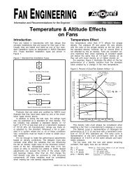
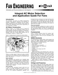
<strong>Series</strong> <strong>14</strong> Fiberglass Pressure Blower<br />
<strong>Aerovent</strong> <strong>Series</strong> <strong>14</strong> Fiberglass Pressure Blowers are recommended<br />
for relatively small, but constant, volumes of air at<br />
high static pressure.<br />
All airstream parts are constructed of fiberglass reinforced<br />
plastic, with excellent corrosion resistance to most chemicals.<br />
The radial type wheel is resin transfer molded (RTM) from a<br />
resin-glass mixture providing optimal strength and corrosion<br />
resistance. All wheels are dynamically and statically balanced<br />
after testing.<br />
Belt driven Arrangement 1 or direct drive Arrangement 8<br />
are available and are supplied with heavy-gauge steel bases,<br />
finished with two coats of light grey epoxy paint. Arrangement<br />
1 can be furnished with a slide rail base for ease in adjusting<br />
belt tension.<br />
<strong>Aerovent</strong> recommends an Arrangement 1 furnished with<br />
an optional steel unitary base constructed of structural channel<br />
and finished with two coats of light grey epoxy paint. This<br />
configuration allows assembly of the fan, motor, and drive as<br />
an integral unit.<br />
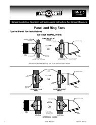
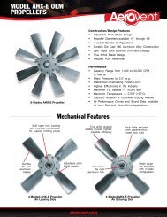
Wheel<br />
Cast from a resin-glass mixture providing<br />
optimal strength and corrosion<br />
resistance.<br />
Accessories<br />
Belt Guard<br />
The belt guard is made of mild steel and is available for all<br />
Arrangement 1 sizes.<br />
Coupling Guard<br />
The coupling guard is made of mild steel and is available for<br />
all Arrangement 8 sizes.<br />
Shaft and Bearing Guard<br />
The mild steel shaft and bearing guard is available on<br />
Arrangements 1 and 8.<br />
Housing Drain<br />
The housing drain is provided with 1" PVC pipe located at the<br />
low point of the scroll.<br />
Flanged Inlet and Outlet<br />
The heavy fiberglass flanged inlet and outlet are standard.<br />
Drilling of holes in the flange is available as an option.<br />
Shaft Seal<br />
The Viton shaft seal rides<br />
against a heavy Teflon<br />
wear plate. It is suitable<br />
for operation up to<br />
225°F.<br />
Graphite Impregnation<br />
Static grounding by graphite impregnation is available as an<br />
option.<br />
316 Stainless Steel Fan Shaft<br />
A 316SS shaft is available as an option.<br />
Special Fiberglass Materials<br />
Dow vinyl ester, Nexus veil, and fire-retardant resin are available<br />
as options.<br />
2 <strong>Aerovent</strong> Bulletin 950
Temperature and Altitude Correction<br />
For Air Density Ratios<br />
The performance tables in this bulletin are based on standard<br />
air density: 70°F at sea level (0.075 lbs./cu.ft. density). The fan<br />
performance tables provide the fan RPM and brake horsepower<br />
requirements for the given CFM and static pressure, at<br />
standard air density.<br />
When the fan performance is not at standard conditions,<br />
the performance must be converted to standard conditions<br />
before entering the fan performance tables. The fan performance<br />
is converted to standard conditions by using the<br />
“Temperature and Altitude Density Ratio” from Table 1<br />
shown below.<br />
The following is an example explaining how to convert the<br />
fan’s performance to standard conditions.<br />
Example: A Size 22/10 <strong>HPBF</strong> is to provide 2,200 CFM at<br />
12" SP, at 200°F at 2,000 ft. elevation (0.056 lbs./cu. ft. density).<br />
• For 200°F and 2,000 ft. elevation, Table 1 shows a density<br />
ratio of 0.747.<br />
• The operating static pressure is 12" SP.<br />
• Using the temperature and altitude density ratio, the<br />
static pressure at standard conditions is determined as<br />
follows:<br />
Operating Temp. & Alt. Static Pressure<br />
Static ÷ Density = at Standard<br />
Pressure Ratio Conditions<br />
For this example:<br />
12" SP ÷ 0.747 =16" SP at Standard Conditions<br />
Turn to page 5 for the Size 22/10 <strong>HPBF</strong> fan performance<br />
table. Using 2,200 CFM at 16" SP at standard conditions, find<br />
the RPM and brake horsepower. The answer is 2,471 RPM<br />
and 9.03 BHP. Note: 9.03 BHP is the brake horsepower<br />
required at standard conditions and is also referred to as the<br />
“cold brake horsepower” or “starting brake horsepower.”<br />
The actual brake horsepower at the operating condition of<br />
200°F and 2,000 ft. elevation is determined by the following<br />
equation:<br />
Brake HP Temp. & Alt. Brake HP<br />
at Standard x Density = at Operating<br />
Conditions Ratio Conditions<br />
For this example:<br />
9.03 x 0.747 = 6.75 BHP at Operating Conditions<br />
Therefore, the Size 22/10 <strong>HPBF</strong> fan providing 2,200 CFM<br />
at 12" SP, at 200°F will run at 2,471 RPM and will require 6.75<br />
BHP at operating conditions and 9.03 BHP at starting.<br />
Maximum Safe Speeds<br />
When operating at temperatures other than 70°F, the maximum<br />
speed of the fan is affected. To determine the maximum<br />
speed, at the operating temperature, a “Maximum Safe Speed<br />
Factor” (Table 3) is applied to the maximum speed of the fan<br />
(Table 2).<br />
Example: The maximum safe speed for a Size 22/10<br />
<strong>HPBF</strong> operating at 200°F is 3,600 RPM. The calculation is<br />
shown below.<br />
Max. RPM<br />
Temp. Factor<br />
Max. RPM<br />
at 70°F x<br />
(Table 3)<br />
= at Operating<br />
(Table 2)<br />
Temp.<br />
For this example:<br />
3,600 x 0.85 = 3,060 Max. RPM at 200°F<br />
Table 2. Table 3.<br />
Max. Safe Speeds (at 70°F) Max. Safe Speed Factors<br />
SIZE<br />
MAX. RPM<br />
18/8 4000<br />
22/10 3600<br />
28/12 2500<br />
Table 4. Metric Conversion Factors<br />
TEMP.<br />
FACTOR<br />
150°F 1.00<br />
200°F 0.85<br />
225°F 0.60<br />
ENGLISH FACTOR METRIC<br />
VOL. FLOW CFM .000472 m 3 /s<br />
PRESSURE SP .24836 kPa<br />
POWER BHP .74570 bkW<br />
VELOCITY FPM .00508 m/s<br />
DENSITY lbs/ft 3 16.018 kg/m 3<br />
SPEED RPM .01667 rps<br />
AREA ft 2 .09290 m 2<br />
CIRCUMFERENCE ft. .30480 m<br />
DIAMETER in. 25.4 mm<br />
Table 1. Temperature and Altitude Density Ratios<br />
ALTITUDE IN FEET ABOVE SEA LEVEL<br />
AIR<br />
0 1000 2000 3000 4000 5000 6000 7000 8000 9000 10000 15000<br />
TEMP<br />
BAROMETRIC PRESSURE IN INCHES OF MERCURY<br />
°F<br />
29.92 28.86 27.82 26.82 25.84 24.90 23.98 23.09 22.22 21.39 20.58 16.89<br />
–50 1.293 1.247 1.201 1.159 1.116 1.076 1.036 .997 .960 .924 .889 .729<br />
0 1.152 1.111 1.071 1.032 .995 .959 .923 .889 .856 .824 .792 .650<br />
50 1.039 1.003 .967 .932 .897 .864 .833 .801 .772 .743 .715 .586<br />
70 1.000 .964 .930 .896 .864 .832 .801 .772 .743 .7<strong>14</strong> .688 .564<br />
100 .946 .912 .880 .848 .818 .787 .758 .730 .703 .676 .651 .534<br />
150 .869 .838 .808 .770 .751 .723 .696 .671 .646 .620 .598 .490<br />
200 .803 .774 .747 .720 .694 .668 .643 .620 .596 .573 .552 .453<br />
250 .747 .720 .694 .669 .645 .622 .598 .576 .555 .533 .5<strong>14</strong> .421<br />
3 <strong>Aerovent</strong> Bulletin 950 <strong>Aerovent</strong> Bulletin 950 3
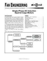
Performance Data<br />
<strong>HPBF</strong> Size 18/8 Fiberglass High Pressure Blower<br />
Wheel Dia.: 18" Tip Speed, FPM = 4.71 x Fan RPM Outlet Dia.: 8" Max. RPM 4000<br />
CFM OV<br />
4" SP 6" SP 8" SP 10" SP 12" SP <strong>14</strong>" SP 16" SP<br />
RPM BHP RPM BHP RPM BHP RPM BHP RPM BHP RPM BHP RPM BHP<br />
175 500 <strong>14</strong>26 0.32<br />
350 1000 <strong>14</strong>13 0.42 1732 0.68 2004 0.99 2245 1.34 2464 1.72 2665 2.13 2852 2.56<br />
525 1500 <strong>14</strong>40 0.58 1739 0.89 1999 1.23 2234 1.59 2448 1.98 2647 2.41 2832 2.87<br />
700 2000 <strong>14</strong>98 0.80 1780 1.17 2026 1.56 2248 1.98 2454 2.41 2645 2.85 2826 3.32<br />
875 2500 1579 1.07 1842 1.50 2077 1.96 2290 2.43 2486 2.92 2669 3.43 2842 3.96<br />
1050 3000 1678 1.42 1923 1.91 2<strong>14</strong>3 2.42 2348 2.96 2537 3.52 27<strong>14</strong> 4.09 2881 4.67<br />
1225 3500 1791 1.86 2018 2.40 2226 2.97 2419 3.57 2600 4.19 2771 4.82 2933 5.47<br />
<strong>14</strong>00 4000 1913 2.40 2128 3.01 2322 3.64 2505 4.29 2677 4.97 2840 5.66 2997 6.38<br />
1575 4500 2041 3.06 2245 3.74 2430 4.43 2602 5.<strong>14</strong> 2766 5.87 2922 6.62 3071 7.38<br />
1750 5000 2176 3.86 2368 4.59 2545 5.35 2710 6.13 2865 6.91 30<strong>14</strong> 7.71 3158 8.54<br />
1925 5500 2313 4.78 2497 5.60 2666 6.42 2825 7.27 2974 8.12 3116 8.98 3252 9.84<br />
2100 6000 2454 5.86 2631 6.77 2792 7.65 2944 8.55 3088 9.47 3225 10.40 3357 11.34<br />
CFM OV<br />
18" SP 20" SP 22" SP 24" SP 26" SP 28" SP 30" SP<br />
RPM BHP RPM BHP RPM BHP RPM BHP RPM BHP RPM BHP RPM BHP<br />
175 500<br />
350 1000 3029 3.02 3196 3.51<br />
525 1500 3007 3.35 3172 3.86 3330 4.39 3480 4.93 3625 5.51 3765 6.10 3899 6.70<br />
700 2000 2997 3.82 3160 4.34 3315 4.88 3464 5.45 3608 6.05 3746 6.66 3879 7.29<br />
875 2500 3007 4.50 3165 5.05 3316 5.61 3462 6.20 3602 6.79 3738 7.41 3869 8.05<br />
1050 3000 3039 5.27 3191 5.88 3337 6.51 3478 7.15 36<strong>14</strong> 7.80 3746 8.46 3874 9.13<br />
1225 3500 3087 6.13 3235 6.81 3376 7.49 3513 8.19 3645 8.90 3772 9.62 3897 10.37<br />
<strong>14</strong>00 4000 3<strong>14</strong>7 7.10 3290 7.84 3428 8.59 3561 9.35 3689 10.11 38<strong>14</strong> 10.90 3935 11.69<br />
1575 4500 3215 8.17 3354 8.97 3489 9.79 3618 10.61 3744 11.45 3865 12.29 3984 13.15<br />
1750 5000 3296 9.38 3429 10.24 3558 11.11 3684 12.00 3807 12.90 3926 13.81<br />
1925 5500 3385 10.74 35<strong>14</strong> 11.66 3639 12.59 3760 13.53 3878 <strong>14</strong>.49 3993 15.46<br />
2100 6000 3483 12.28 3606 13.24 3728 <strong>14</strong>.24 3845 15.23 3959 16.24<br />
Underlined figures indicate maximum static efficiency.<br />
<strong>HPBF</strong> Size 22/10 Fiberglass High Pressure Blower<br />
Wheel Dia.: 22" Tip Speed, FPM = 5.76 x Fan RPM Outlet Dia.: 10" Max. RPM 3600<br />
CFM OV<br />
4" SP 6" SP 8" SP 10" SP 12" SP <strong>14</strong>" SP 16" SP 18" SP<br />
RPM BHP RPM BHP RPM BHP RPM BHP RPM BHP RPM BHP RPM BHP RPM BHP<br />
275 500 1157 0.39 <strong>14</strong>25 0.66<br />
550 1000 1139 0.56 1398 0.89 1620 1.27 1817 1.68 1996 2.12 2160 2.59 23<strong>14</strong> 3.09 2458 3.60<br />
825 1500 1170 0.82 <strong>14</strong>05 1.23 1611 1.67 1800 2.13 1974 2.62 2136 3.15 2287 3.70 2430 4.28<br />
1100 2000 1236 1.13 <strong>14</strong>51 1.66 1643 2.19 1818 2.73 1980 3.30 2132 3.89 2277 4.50 2415 5.12<br />
1375 2500 1326 1.56 1522 2.12 1699 2.80 1864 3.45 2017 4.11 2161 4.78 2297 5.46 2427 6.16<br />
1650 3000 <strong>14</strong>30 2.20 1612 2.74 1777 3.41 1928 4.22 2073 5.02 2210 5.81 2340 6.59 2464 7.38<br />
1925 3500 1544 2.89 1713 3.72 1868 4.31 2012 5.02 2<strong>14</strong>6 5.93 2274 6.89 2398 7.82 2517 8.73<br />
2200 4000 1662 3.80 1825 4.68 1969 5.63 2105 6.30 2235 7.02 2356 7.97 2471 9.03 2583 10.13<br />
2475 4500 1783 4.97 1940 5.82 2080 6.88 2208 7.96 2329 8.77 2447 9.44 2559 10.40 2665 11.51<br />
2750 5000 1908 6.39 2059 7.30 2195 8.32 2318 9.51 2434 10.72 2544 11.73 2651 12.44 2755 13.29<br />
3025 5500 2034 8.03 2181 9.09 2312 10.10 2433 11.27 2545 12.60 2650 13.93 2752 15.<strong>14</strong> 2851 16.06<br />
3300 6000 2163 9.94 2305 11.17 2433 12.28 2550 13.41 2659 <strong>14</strong>.69 2762 16.15 2860 17.62 2954 19.00<br />
CFM OV<br />
20" SP 22" SP 24" SP 26" SP 28" SP 30" SP 32" SP 34" SP 36" SP<br />
RPM BHP RPM BHP RPM BHP RPM BHP RPM BHP RPM BHP RPM BHP RPM BHP RPM BHP<br />
275 500<br />
550 1000 2595 4.15 2725 4.71 2850 5.30 2969 5.90<br />
825 1500 2565 4.88 2694 5.51 2817 6.15 2936 6.82 3050 7.50 3160 8.20 3267 8.93 3370 9.66 3471 10.42<br />
1100 2000 2547 5.77 2674 6.44 2795 7.<strong>14</strong> 2912 7.85 3025 8.60 3134 9.36 3240 10.15 3342 10.94 3442 11.76<br />
1375 2500 2552 6.90 2673 7.65 2789 8.40 2902 9.17 3012 9.96 3119 10.76 3223 11.59 3324 12.43 3422 13.28<br />
1650 3000 2584 8.19 2698 9.00 2809 9.83 2917 10.69 3021 11.56 3123 12.45 3223 13.35 3320 <strong>14</strong>.25 3416 15.18<br />
1925 3500 2632 9.65 2742 10.57 2849 11.49 2952 12.42 3053 13.37 3151 <strong>14</strong>.33 3246 15.29 3340 16.29 3431 17.29<br />
2200 4000 2692 11.20 2799 12.25 2902 13.30 3001 <strong>14</strong>.33 3099 15.39 3193 16.43 3286 17.50 3376 18.57 3464 19.64<br />
2475 4500 2767 12.70 2867 13.93 2965 15.16 3062 16.36 3156 17.54 3247 18.70 3337 19.89 3424 21.06 3510 22.24<br />
2750 5000 2855 <strong>14</strong>.41 2950 15.63 3043 16.95 3134 18.32 3223 19.69 3311 21.05 3397 22.36 3482 23.67 3566 24.99<br />
3025 5500 2947 16.82 3041 17.83 3131 19.04 3219 20.38 3304 21.80 3387 23.28 3469 24.78 3550 26.30<br />
3300 6000 3046 20.19 3136 21.09 3224 21.94 3310 23.03 3393 24.33 3474 25.76 3553 27.27<br />
Underlined figures indicate maximum static efficiency.<br />
Performance shown is for installation type B: Free inlet, Ducted outlet.<br />
Power rating (BHP) does not include drive losses.<br />
Performance ratings do not include the effects of appurtenances in the airstream.<br />
4 <strong>Aerovent</strong> Bulletin 950
<strong>HPBF</strong> Size 28/12 Fiberglass High Pressure Blower<br />
Wheel Dia.: 28" Tip Speed, FPM = 7.33 x Fan RPM Outlet Dia.: 12" Max. RPM 2500<br />
CFM OV<br />
4" SP 6" SP 8" SP 10" SP 12" SP <strong>14</strong>" SP 16" SP<br />
RPM BHP RPM BHP RPM BHP RPM BHP RPM BHP RPM BHP RPM BHP<br />
395 500<br />
790 1000 882 0.76<br />
1185 1500 895 1.10 1081 1.66 1247 2.27 1397 2.91<br />
1580 2000 935 1.56 1107 2.23 1260 2.94 1398 3.68 1527 4.46 1649 5.27 1765 6.12<br />
1975 2500 994 2.16 1151 2.94 1293 3.76 <strong>14</strong>24 4.63 1545 5.51 1659 6.42 1767 7.36<br />
2370 3000 1064 2.91 1210 3.85 1341 4.78 <strong>14</strong>63 5.74 1579 6.75 1688 7.79 1791 8.84<br />
2765 3500 1<strong>14</strong>1 3.84 1278 4.93 <strong>14</strong>02 6.02 1517 7.12 1624 8.21 1727 9.35 1826 10.52<br />
3160 4000 1224 4.99 1353 6.22 <strong>14</strong>69 7.45 1578 8.70 1681 9.95 1778 11.20 1871 12.47<br />
3555 4500 1312 6.38 <strong>14</strong>33 7.76 1544 9.<strong>14</strong> 1647 10.53 1744 11.92 1838 13.34 1927 <strong>14</strong>.74<br />
3950 5000 <strong>14</strong>03 8.04 1517 9.56 1622 11.08 1721 12.63 18<strong>14</strong> <strong>14</strong>.17 1903 15.73 1989 17.30<br />
4345 5500 <strong>14</strong>95 9.97 1605 11.67 1705 13.34 1799 15.02 1889 16.73 1974 18.42 2056 20.13<br />
4740 6000 1589 12.21 1695 <strong>14</strong>.09 1791 15.93 1881 17.76 1967 19.60 2049 21.44 2128 23.30<br />
CFM OV<br />
18" SP 20" SP 22" SP 24" SP 26" SP 28" SP 30" SP<br />
RPM BHP RPM BHP RPM BHP RPM BHP RPM BHP RPM BHP RPM BHP<br />
395 500<br />
790 1000<br />
1185 1500<br />
1580 2000 1875 6.99 1979 7.89<br />
1975 2500 1871 8.35 1970 9.33 2067 10.36 2161 11.42 2251 12.49 2338 13.58 2423 <strong>14</strong>.71<br />
2370 3000 1889 9.91 1984 11.02 2075 12.<strong>14</strong> 2163 13.29 2248 <strong>14</strong>.46 2331 15.64 2413 16.87<br />
2765 3500 1921 11.73 2011 12.93 2099 <strong>14</strong>.17 2184 15.44 2266 16.71 2345 17.99 2423 19.32<br />
3160 4000 1961 13.76 2049 15.11 2133 16.46 2215 17.84 2294 19.22 2371 20.63 2446 22.06<br />
3555 4500 2012 16.<strong>14</strong> 2094 17.55 2175 19.02 2254 20.51 2331 22.03 2405 23.54 2478 25.09<br />
3950 5000 2072 18.87 2151 20.42 2227 21.96 2302 23.55 2375 25.15 2447 26.79<br />
4345 5500 2135 21.84 2212 23.56 2287 25.29 2359 27.00 2429 28.72 2497 30.43<br />
4740 6000 2204 25.16 2278 27.03 2350 28.91 2420 30.78 2489 32.68<br />
Underlined figures indicate maximum static efficiency.<br />
Performance shown is for installation type B: Free inlet, Ducted outlet.<br />
Power rating (BHP) does not include drive losses.<br />
Performance ratings do not include the effects of appurtenances in the airstream.<br />
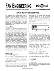
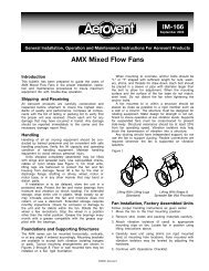
Dimensional Data<br />
Arrangement 1<br />
(V) Qty. (W) Dia. Holes<br />
Optional Flange Drilling<br />
Arr. #8 Size<br />
Determined<br />
By Motor Size<br />
(4) 9/16 Dia. Holes<br />
NOTE: Phantom drawing illustrates an Arrangement #8 <strong>Model</strong> <strong>HPBF</strong> pressure blower.<br />
SIZE SHAFT DIA. A B C D a b c d E F G H J<br />
18" – 8" 1 1 ⁄2 18 3 ⁄8 17 <strong>14</strong> 10 1 ⁄2 13 5 ⁄8 20 1 ⁄8 <strong>14</strong> 3 ⁄8 12 7 ⁄8 12 1 ⁄2 <strong>14</strong> 3 ⁄4 13 1 ⁄4 24 1 ⁄4 6 5 ⁄8<br />
22" – 10" 1 1 ⁄2 24 3 ⁄8 22 18 3 ⁄16 <strong>14</strong> 7 ⁄8 17 5 ⁄8 31 1 ⁄8 18 5 ⁄8 16 5 ⁄8 16 3 ⁄16 19 3 ⁄16 17 3 ⁄16 24 7 ⁄16 6 3 ⁄4<br />
28" – 12" 1 15 ⁄16 30 28 22 3 ⁄4 18 7 ⁄8 22 39 5 ⁄8 23 1 ⁄4 20 3 ⁄4 20 1 ⁄4 24 21 1 ⁄2 26 5 ⁄8 8<br />
SIZE K L M N R S T U V W Y Z B.C. O.D. I.D.<br />
18" – 8" 3 1 ⁄2 6 7 ⁄8 7 17 5 ⁄8 4 5 ⁄8 12 8 3 ⁄4 9 5 ⁄8 8 7<br />
⁄8 22 1 ⁄2 45 11 3 ⁄4 13 1 ⁄2 8<br />
22" – 10" 4 9 7 1 ⁄8 17 11 ⁄16 4 11 ⁄16 12 11 11 7 ⁄8 12 1 15 30 <strong>14</strong> 1 ⁄4 16 10<br />
28" – 12" 5 12 9 18 5 ⁄8 5 21 ⁄32 12 12 3 ⁄8 13 1 ⁄4 12 1 15 30 17 19 12<br />
See page 7 for discharge positions.<br />
5 <strong>Aerovent</strong> Bulletin 950 <strong>Aerovent</strong> Bulletin 950 5
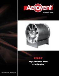
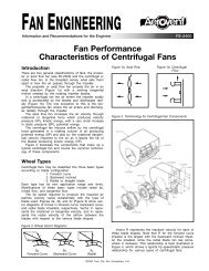
Dimensional Data<br />
Arrangement 9<br />
C<br />
B<br />
O.D.<br />
I.D.<br />
B.C.<br />
F<br />
D<br />
K REF.<br />
Y<br />
Z<br />
"W" DIA. HOLES<br />
(V) REQ'D<br />
L<br />
O.D.<br />
OPTIONAL<br />
FLANGE DRILLING<br />
A<br />
9/16 DIA.<br />
THRU (4)<br />
T<br />
U<br />
Q<br />
P<br />
S<br />
N<br />
H<br />
R<br />
M<br />
J<br />
SIZE SHAFT DIA. A B C D a b c d E F G H J<br />
18" – 8" 1 1 ⁄2 18 3 ⁄8 17 <strong>14</strong> 10 1 ⁄2 13 5 ⁄8 20 1 ⁄8 <strong>14</strong> 3 ⁄8 12 7 ⁄8 12 1 ⁄2 <strong>14</strong> 3 ⁄4 13 1 ⁄4 34 1 ⁄4 6 5 ⁄8<br />
22" – 10" 1 1 ⁄2 24 3 ⁄8 22 18 3 ⁄16 <strong>14</strong> 7 ⁄8 17 5 ⁄8 31 1 ⁄8 18 5 ⁄8 16 5 ⁄8 16 3 ⁄16 19 3 ⁄16 17 3 ⁄16 39 1 ⁄16 6 3 ⁄4<br />
28" – 12" 1 15 ⁄16 30 28 22 3 ⁄4 18 7 ⁄8 22 39 5 ⁄8 23 1 ⁄4 20 3 ⁄4 20 1 ⁄4 24 21 1 ⁄2 43 11 ⁄16 8<br />
SIZE K L M N P Q R S T U V W Y Z O.D. I.D. B.C.<br />
18" – 8" 4 6 7 ⁄8 7 27 5 ⁄8 34 5 ⁄16 33 7 ⁄16 5 5 ⁄8 17 8 3 ⁄4 9 5 ⁄8 8 7<br />
⁄8 22 1 ⁄2 45 13 1 ⁄2 8 11 3 ⁄4<br />
22" – 10" 4 9 7 1 ⁄8 32 5 ⁄16 36 7 ⁄8 35 5 ⁄8 5 13 ⁄16 20 1 ⁄2 10 3 ⁄16 11 7 ⁄8 12 1 15 30 16 10 <strong>14</strong> 1 ⁄4<br />
28" – 12" 5 12 9 35 11 ⁄16 39 1 ⁄2 38 1 ⁄4 6 11 ⁄16 28 11 3 ⁄4 13 12 1 15 30 19 12 17<br />
See page 7 for discharge positions. Please note that clockwise 45° downblast and counter-clockwise bottom horizontal discharges<br />
are not available on Arrangement 9 units.<br />
Arrangement 10<br />
C<br />
B<br />
O.D.<br />
I.D.<br />
B.C.<br />
F<br />
D<br />
OPTIONAL<br />
WEATHER COVER<br />
K REF.<br />
Y<br />
Z<br />
"W" DIA. HOLES<br />
(V) REQ'D<br />
L<br />
O.D.<br />
OPTIONAL<br />
FLANGE DRILLING<br />
A<br />
T<br />
U<br />
(4) 9/16 DIA. HOLES<br />
T<br />
U<br />
E<br />
S<br />
N<br />
H<br />
R<br />
M<br />
J<br />
SIZE SHAFT DIA. A B C D a b c d E F G H J<br />
18" – 8" 1 1 ⁄2 19 7 ⁄8 17 <strong>14</strong> 10 1 ⁄2 13 5 ⁄8 20 1 ⁄8 <strong>14</strong> 3 ⁄8 12 7 ⁄8 12 1 ⁄2 <strong>14</strong> 3 ⁄4 13 1 ⁄4 33 3 ⁄4 6 5 ⁄8<br />
22" – 10" 1 1 ⁄2 23 5 ⁄16 22 18 3 ⁄16 <strong>14</strong> 7 ⁄8 17 5 ⁄8 31 1 ⁄8 18 5 ⁄8 16 5 ⁄8 16 3 ⁄16 19 3 ⁄16 17 3 ⁄16 38 3 ⁄4 6 3 ⁄4<br />
28" – 12" 1 15 ⁄16 31 1 ⁄8 28 22 3 ⁄4 18 7 ⁄8 22 39 5 ⁄8 23 1 ⁄4 20 3 ⁄4 20 1 ⁄4 24 21 1 ⁄2 43 5 ⁄8 8<br />
SIZE K L M N R S T U V W Y Z O.D. I.D. B.C.<br />
18" – 8" 4 6 7 ⁄8 7 27 1 ⁄8 6 3 ⁄8 19 8 13 ⁄16 9 5 ⁄16 8 7<br />
⁄8 22 1 ⁄2 45 13 1 ⁄2 8 11 3 ⁄4<br />
22" – 10" 4 9 7 1 ⁄8 32 6 3 ⁄4 23 1 ⁄4 10 7 ⁄8 11 1 ⁄2 12 1 15 30 16 10 <strong>14</strong> 1 ⁄4<br />
28" – 12" 5 12 9 35 5 ⁄8 8 5 ⁄8 24 1 ⁄2 12 1 ⁄8 13 12 1 15 30 19 12 17<br />
See page 7 for discharge positions.<br />
6 <strong>Aerovent</strong> Bulletin 950
Discharge Positions<br />
DISCHARGE<br />
POSITION<br />
TOP<br />
HORIZONTAL<br />
BOTTOM<br />
HORIZONTAL<br />
UPBLAST<br />
TOP<br />
45 DOWN<br />
BOTTOM<br />
45 UP<br />
TOP<br />
45 UP<br />
CLOCK-<br />
WISE<br />
ROTATION<br />
COUNTER-<br />
CLOCK-<br />
WISE<br />
Special construction is required for clockwise and counterclockwise downblast positions.<br />
* Discharge position not available on Arrangement 9 units.<br />
Typical Specifications<br />
Fans shall be of the Fiberglass Reinforced Plastic Pressure Blower type, as manufactured by <strong>Aerovent</strong>, Minneapolis, Minnesota, and shall be of<br />
the size and capacity as indicated in the fan schedule. Centrifugal fans shall be tested in accordance with ANSI/ASHRAE 51-1985 and ANSI/<br />
AMCA 210-85 test codes and guaranteed by the manufacturer to deliver at the rated published performance levels. In addition, each unit shall be<br />
factory run tested prior to shipment.<br />
CONSTRUCTION — All airstream components shall be fabricated of corrosion resistant fiberglass reinforced polyester resin. The radial type<br />
wheel shall be resin transfer molded from a resin-glass mixture, providing optimal strength and corrosion resistance and an extremely smooth<br />
surface to maximize aerodynamic performance. The fan housing shall be molded of fiberglass reinforced polyester.<br />
ARRANGEMENT — The pressure blower shall be fabricated for either belt driven Arrangement 1 or direct drive Arrangement 8 configuration<br />
as indicated in the fan schedule. Where indicated on the drawings or schedules, the Arrangement 1 pressure blower may be furnished with a<br />
unitary base to allow mounting of the fan and motor on a common frame.<br />
WHEEL — The radial type wheel is resin transfer molded (RTM) from a resin-glass mixture providing optimal strength and corrosion resistance.<br />
All wheels are dynamically and statically balanced after testing.<br />
BEARINGS — Bearings shall be oversized to ensure maximum bearing life. The belts and sheaves furnished by the manufacturer shall be<br />
selected to provide additional allowances of 1.3 to 2 times the normal satisfactory capacity.<br />
Balancing — The propeller assembly shall be statically and dynamically balanced in accordance with ANSI/AMCA 204-96 “Balance Quality<br />
and Vibration Levels for Fans” to Fan Application Category BV-3, Balance Quality Grade G6.3. In addition, belt driven fan propellers shall be<br />
balanced on the fan shaft after final assembly in the fan casing, in the manufacturing facility, to the following peak velocity values, filter-in, at the<br />
fan test speed:<br />
Fan Application Category Rigidly Mounted - (in./s) Flexibly Mounted - (in./s)<br />
BV-3 0.15 0.20<br />
MOTORS — Fan motors shall be foot mounted NEMA A Design B, standard industrial continuous duty, ball bearing (ODP, TEFC, FXCP),<br />
variable torque type suitable for operation on voltage, phase, and hertz, as listed in the fan schedule. Motor bearings shall have a minimum L-10<br />
life, as defined by AFBMA, of at least 40,000 hours (200,000 hours average life).<br />
FINISH — All steel parts are finished with an air dry epoxy paint. All fiberglass parts are coated inside and outside with resin (with UV inhibitor),<br />
approximately 10 mils in thickness, to seal the surface and provide a smooth, shiny finish. Optional resins and finishes include:<br />
• Dow Vinyl Ester • Nexus Surface Veil • Fire-Retardant Resin<br />
ACCESSORIES — The units shall be furnished complete with:<br />
• Flange Drilling<br />
• Nexus Veil<br />
• Drain<br />
• Belt Guard, OSHA<br />
• Graphite Impregnation with Static Grounding<br />
• Coupling Guard (Arrangement 1 Only)<br />
• Viton Shaft Seal<br />
• 316SS Shaft<br />
• Dow Vinyl Ester<br />
• Silica Sand Airstream<br />
• Unitary Base<br />
• Vibration Isolation (RIS/Spring)<br />
• Shaft & Bearing Guard, GT Type<br />
©2004 <strong>Aerovent</strong><br />
Bulletin illustrations cover the general appearance of products at the time of publication, and<br />
we reserve the right to make changes in design and construction at any time without notice.<br />
7 <strong>Aerovent</strong> Bulletin 950 <strong>Aerovent</strong> Bulletin 950 7
PROPELLER FANS | TUBEAXIAL & VANEAXIAL FANS | CENTRIFUGAL FANS & BLOWERS | ROOF VENTILATORS<br />
INDUSTRIAL AIR HANDLERS | AIR MAKE-UP | FIBERGLASS FANS | CUSTOM FANS<br />
®<br />
AEROVENT<br />
A Twin City Fan Company<br />
WWW.AEROVENT.COM<br />
5959 Trenton Lane N | Minneapolis, MN 55442 | Phone: 763-551-7500 | Fax: 763-551-7501