Design for Flip-Chip and Chip-Size Package Technology - IPC Outlook
Design for Flip-Chip and Chip-Size Package Technology - IPC Outlook
Design for Flip-Chip and Chip-Size Package Technology - IPC Outlook

Create successful ePaper yourself
Turn your PDF publications into a flip-book with our unique Google optimized e-Paper software.
As originally published in the <strong>IPC</strong> APEX EXPO Proceedings.<br />
<strong>Design</strong> <strong>for</strong> <strong>Flip</strong>-<strong>Chip</strong> <strong>and</strong> <strong>Chip</strong>-<strong>Size</strong> <strong>Package</strong> <strong>Technology</strong><br />
Vern Solberg<br />
Solberg <strong>Technology</strong> Consulting<br />
Madison, Wisconsin<br />
Abstract<br />
As new generations of electronic products emerge they often surpass the capability of existing packaging <strong>and</strong><br />
interconnection technology <strong>and</strong> the infrastructure needed to support newer technologies. This movement is occurring at<br />
all levels: at the IC, at the IC package, at the module, at the hybrid, the PC board which ties all the systems together.<br />
Interconnection density <strong>and</strong> methodology becomes the measure of successfully managing per<strong>for</strong>mance. The gap<br />
between printed boards <strong>and</strong> semiconductor technology (wafer level integration) is greater than one order of magnitude<br />
in interconnection density capability, although the development of fine-pitch substrates <strong>and</strong> assembly technology has<br />
narrowed the gap somewhat. All viable ef<strong>for</strong>ts are being used in filling this void utilizing uncased integrated circuits<br />
(flip-chip) <strong>and</strong> incorporating more than one die or more than one part in the assembly process.<br />
This paper provides a comparison of different commonly used technologies including flip-chip, chip-size <strong>and</strong> wafer level<br />
array package methodologies detailed in a new publication, <strong>IPC</strong>-7094. It considers the effect of bare die or die-size<br />
components in an uncased or minimally cased <strong>for</strong>mat, the impact on current component characteristics <strong>and</strong> reviews the<br />
appropriate PCB design guidelines to ensure efficient assembly processing. The focus of the <strong>IPC</strong> document is to<br />
provide useful <strong>and</strong> practical in<strong>for</strong>mation to those who are considering the adoption of bare die or die size array<br />
components.<br />
Introduction<br />
The flip-chip process was originally established <strong>for</strong> applications requiring aggressive miniaturization. Initially developed by<br />
IBM <strong>for</strong> the Solid Logic <strong>Technology</strong> (SLT) hybrid electronic circuitry <strong>for</strong> their System 360 computers, the die were very<br />
small <strong>and</strong> had very few contacts. The perimeter located bond sites were, as they are to a degree today, prepared with alloy<br />
bumps enabling the uncased semiconductor die to be bonded directly to a substrate using surface mount processes. In<br />
developing the <strong>IPC</strong>-7094, „<strong>Design</strong> <strong>and</strong> Assembly Process Implementation <strong>for</strong> <strong>Flip</strong>-<strong>Chip</strong> <strong>and</strong> Die <strong>Size</strong> Components’, a number<br />
of experts were assembled to address the industries need <strong>for</strong> practical <strong>and</strong> up-to-date in<strong>for</strong>mation <strong>and</strong> guidance in how to<br />
employ the uncased as well as minimally packaged semiconductor elements being offered to the commercial market. A<br />
number of miniature package solutions have evolved as well that retain an outline that is the same or very near the same as<br />
the die element. The uncased die element, when processed <strong>for</strong> in the wafer <strong>for</strong>mat <strong>for</strong> board level attachment, is identified as<br />
a wafer level BGA (WLBGA). A family of die-size BGA (DSBGA) is a component that employs a package assembly<br />
process utilizing an intermediate interposer to add a level of physical robustness, enable more efficient electrical test, burn-in<br />
<strong>and</strong> board level assembly.<br />
Because of the rapid movement toward semiconductor package miniaturization, members of the Joint Electronic Device<br />
Engineering Council (JEDEC) developed a number of st<strong>and</strong>ards to help maintain a degree of uni<strong>for</strong>mity <strong>for</strong> the<br />
semiconductor devices final configuration. Its membership includes semiconductor manufacturers, packaging services<br />
companies, material suppliers <strong>and</strong> users. The organizations JC-11 subcommittee is responsible <strong>for</strong> developing the mechanical<br />
outline requirements <strong>for</strong> solid state semiconductor packaging. The two st<strong>and</strong>ards that the <strong>IPC</strong>-7094 document has focused on<br />
are JEDEC 95 Publication „<strong>Design</strong> Guide 4.18‟ (WLBGA) <strong>and</strong> „<strong>Design</strong> Guide 4.7‟ <strong>for</strong> DSBGA. Their definition is as<br />
follows:<br />
<br />
<br />
A Wafer Level Ball Grid Array (WLBGA) has an array of metallic balls on the underside of the package. The<br />
substrate of the package is the semiconductor die with or without a redistribution layer that may have a square or<br />
rectangular shape with metallic balls applied onto the circuit side of the die. The array pattern of metallized balls<br />
provides the mechanical <strong>and</strong> electrical connection from the package body to the next level component such as a<br />
printed circuit board or intermediate substrate.<br />
A Die-size Ball Grid Array (DSBGA) also has an array of metallic balls on the underside of the package. The die<br />
elements are, however, attached to a dielectric substrate or carrier <strong>for</strong> redistribution of the die bond pads to a<br />
uni<strong>for</strong>m contact array pattern. The package substrate may have a square or rectangular shape with a metalized circuit<br />
pattern applied to one or both sides of a dielectric structure. The size of the substrate or carrier is as close to the die<br />
size as practically possible.
As originally published in the <strong>IPC</strong> APEX EXPO Proceedings.<br />
The contacts on the WLBGA <strong>and</strong> DSBGA are balls, bumps or other protruding terminals constructed from a variety of alloy<br />
<strong>and</strong>/or polymer materials. The alloy ball or bump features are added to each contact site to provide the mechanical <strong>and</strong><br />
electrical connection from the package body to the next level component such as a printed circuit board. Typically, when<br />
balls are present, they consist of eutectic lead/tin solder or a lead-free solder alloy. For purposes of the JEDEC documents,<br />
these contacts of whatever final <strong>for</strong>m are referenced generically as “balls”. In regard to accommodation <strong>for</strong> board level<br />
assembly processing, the perimeter bumping process is generally limited to mounting uncased die having a relatively few<br />
contact sites. Larger die requiring higher pin count, will likely be processed to redistribute the peripheral located wire-bond<br />
sites to a uni<strong>for</strong>m area array <strong>for</strong>mat. When the contact sites are arranged in the array package <strong>for</strong>mat it furnishes a more<br />
uni<strong>for</strong>m interface configuration that better accommodates component level test, better access <strong>for</strong> circuit routing <strong>and</strong> is more<br />
compatibility with established surface mount assembly processes.<br />
The profile height of the WLBGA <strong>and</strong> DSBGA devices are very thin. The finished devices are not encased in plastic typical<br />
of the coarser pitch BGA families, however, some suppliers may furnish these miniature components with a thin polymer<br />
coating to protect the exposed silicon surface. The actual height of the array device is defined as the distance from the<br />
seating plane (the surface of the mating circuit board) to the highest point on the package body. This distance is measured<br />
perpendicularly to the seating plane.<br />
Applications<br />
H<strong>and</strong>-held communication <strong>and</strong> entertainment products will continue to dominate the consumer markets worldwide <strong>and</strong>, with<br />
each generation offering more <strong>and</strong> more features <strong>and</strong>/or capability, system level integration <strong>and</strong> miniaturization becomes<br />
more of a priority. And even though the actual applications <strong>and</strong> functionality of the new product offering exp<strong>and</strong>s, the<br />
customer is expecting each generation to be smaller <strong>and</strong> lighter that its predecessor. Semiconductor elements widely targeted<br />
<strong>for</strong> improving package per<strong>for</strong>mance <strong>and</strong> package size reduction include both logic <strong>and</strong> memory. High volume consumer<br />
products requiring greater memory component density include:<br />
<br />
<br />
<br />
<br />
<br />
MP3 players, portable media players<br />
Memory cards (mini SD, SD, MMC etc.)<br />
Digital Still Cameras (DSC)<br />
H<strong>and</strong>held video games<br />
Solid State Drives <strong>for</strong> mobile computing<br />
Consumer applications may include a number of the functions unique to the product. For wireless h<strong>and</strong>sets, <strong>for</strong> example,<br />
companies are looking <strong>for</strong> miniature package solutions <strong>for</strong> all functions.<br />
Array packaging has evolved as the most direct method <strong>for</strong> package-to-board interface since there is no intermediate leadframe<br />
required. The die prepared <strong>for</strong> flip-chip applications enables increased circuit density which can contribute to improved<br />
electrical per<strong>for</strong>mance. When comparing the WLBGA <strong>and</strong> DSBGA semiconductor packaging to the QFP lead-frame package,<br />
the surface area differences are quite dramatic. Table 1 provides a comparison of different semiconductor packaging methods<br />
having a common 10 mm x 10 mm die element with 100 active contact features.<br />
Table 1: Comparative Table of Various Technologies <strong>for</strong> a 100 I/O, 10x10 mm <strong>Size</strong> Die<br />
Source: <strong>IPC</strong>-7094
As originally published in the <strong>IPC</strong> APEX EXPO Proceedings.<br />
WLBGA Challenges<br />
Three primary factors that must be addressed when adopting WLBGA include; per<strong>for</strong>mance, reliability <strong>and</strong> cost. Although<br />
each factor carries equal status when assessing the merits of any flip-chip or re-distributed array packaging innovations, cost<br />
of the product will always influence adoption of one technology over the other. When companies choose to adopt uncased<br />
WLCSP semiconductors several issues should be considered:<br />
<br />
<br />
<br />
<br />
<br />
How to manage multiple IC vendors<br />
Availability of Known Good Die (test <strong>and</strong> burn-in)<br />
Die <strong>and</strong> wafer availability/uni<strong>for</strong>m quality<br />
Compound yield expectation <strong>for</strong> less mature ICs<br />
Accommodating future die shrinks<br />
A number of single-die wafer-level package innovations have been developed <strong>for</strong> a broad market; however, many<br />
supplier companies are not able to meet acceptable manufacturing yields. This is due in part to the difficulty of<br />
simultaneous testing of die while in the wafer <strong>for</strong>mat. The definition of KQD is that the supplier will demonstrate with<br />
data that the defect level <strong>and</strong> early failure rate estimates on die shipments are within the negotiated rang e, <strong>and</strong> retain a<br />
level of confidence in those estimates. Wafer level probe test is typically employed to per<strong>for</strong>m only basic analysis <strong>and</strong><br />
is not widely utilized <strong>for</strong> per<strong>for</strong>mance sorting, reliability screening or massively parallel contacting. If the uncased die<br />
elements are only to be tested while in the wafer <strong>for</strong>mat, the user still expects the same quality <strong>and</strong> reliability level of<br />
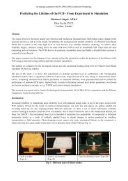
packaged part. The most thorough <strong>and</strong> reliable electrical testing is when bump or ball contacts are furnished on a<br />
singulated die element (see Figure 1), allowing each device to be socketed.<br />
Source: Micron Semiconductor<br />
Figure 1. The uncased WLBGA, when prepared with compatible alloy<br />
bump contacts, can be socketed <strong>for</strong> electrical testing.<br />
The <strong>IPC</strong>-7094 document notes that, the term “Known Quality Die”, (KQD) does not depend on exact definitions of die<br />
quality <strong>and</strong> reliability in terms of defect levels or early failure rates, but instead offers the die supplier <strong>and</strong> user the<br />
opportunity to negotiate the price, quality <strong>and</strong> reliability targets needed to satisfy the system-level cost, yield <strong>and</strong> warranty<br />
requirements.<br />
Wafer Level <strong>Package</strong> Process Variations<br />
The basic wafer level process begins with the under-bump (UB) metallization <strong>and</strong> bumping of the contact sites at the die<br />
perimeter. All of this work takes place while the die elements remain in the wafer-level <strong>for</strong>mat. The first metallization layer<br />
(typically chromium) is used to create a good bond to the aluminum pad initially prepared <strong>for</strong> the wire-bond processes.<br />
Subsequent metal films, typically copper <strong>and</strong> gold, are deposited to provide solderability <strong>for</strong> mounting the small ball contacts.<br />
It is common practice to first sputter an adhesion layer on in advance of the metals used to provide the required conductivity<br />
to the circuit. Adhesion-promoting metals include: nickel (Ni), molybdenum (Mo), chrome (Cr), tungsten (W), <strong>and</strong> titanium<br />
(Ti). These base materials are then over-plated with a more conductive metal such copper, gold, tin <strong>and</strong> palladium. Originally,<br />
the ball contact was an alloy of Au-Sn eutectic which melted at 360°C; there<strong>for</strong>e, the pad was called the ball-limiting<br />
metallurgy because the melted ball would not wet the glass passivation on the die surface beyond the area of the pad.
As originally published in the <strong>IPC</strong> APEX EXPO Proceedings.<br />
Later the Au-Sn ball contact was replaced by a Ni-Au plated solid copper ball attached with a Pb-Sn alloy to maintain a more<br />
uni<strong>for</strong>m „st<strong>and</strong>-off‟ height. The ball contact alloys of greatest favor today is SnPb eutectic or (<strong>for</strong> lead-free assembly) a<br />
SnAgCu composition.<br />
Redistribution methods are utilized when the existing bond pad locations are not practical <strong>for</strong> board-level assembly. I/O<br />
redistribution is a sequential process where additional dielectric <strong>and</strong> conductive layers are added to the wafers active surface.<br />
The process can provide a uni<strong>for</strong>m contact grid pattern that can enables a st<strong>and</strong>ard contact assignment to better facilitate<br />
component level testing <strong>and</strong> board or module level assembly. Dimensional control is a vital factor in the implementation of<br />
WLBGA assembly. Factors affecting the successful implementation of wafer-level processing are stabilized die element<br />
outline dimensions <strong>and</strong> wire-bond pad location <strong>and</strong> size. The metallization process allows the wire-bond sites to be routed to<br />
a uni<strong>for</strong>m contact pitch to accommodate the ball or bump contact application. Process control in the bump or ball application<br />
process is paramount. Even small dimensional differences in bump profile <strong>and</strong> size can translate into uneven stress balance of<br />
the solder joining process that can affect end product reliability.<br />
In regard to planning ahead <strong>for</strong> the potential of „die shrink‟, suppliers often attempt to refine the die to gain higher yield or to<br />
enable additional units to be furnished within the fixed wafer area. With each revision or refinement, the die could shrink 5%<br />
to 10% in area, changing the die outline <strong>and</strong> often rearranging the wire-bond sites. This occurrence often leads to major<br />
redesign of the circuit board as well as the package substrate <strong>for</strong> the DSBGA. To minimize the impact of die shrink, all the<br />
active signal, power <strong>and</strong> ground contacts should be located in the die interior <strong>and</strong> locate any contacts used <strong>for</strong> redundant<br />
<strong>and</strong>/or mechanical support toward the outer area of the die. When the shrink occurs, the outer, less essential rows will be lost,<br />
but the critical contacts will not be affected. As the chip shrinks so does the „Distance to the Neutral Point‟ (DNP), making<br />
the loss of redundant <strong>and</strong> mechanical contacts less of a reliability issue. With this approach, the next level of assembly is not<br />
affected as the non-critical connections simply become open pins. If the die undergoes excessive shrinks the contact array<br />
matrix will likely need to be re-established with a reduced contact pitch <strong>and</strong> contact size.<br />
Die <strong>Size</strong> Array <strong>Package</strong> Assembly Process<br />
Die size (DSBGA) array package technology has evolved using widely differing constructions including a number or<br />
proprietary packaging methodologies. Many applications have been successful in employing flip-chip technology, however,<br />
when h<strong>and</strong>ling <strong>and</strong> testing the uncased die, users realize that without some <strong>for</strong>m of rein<strong>for</strong>cement (post assembly underfill or<br />
encapsulation) that they are prone to cracking <strong>and</strong>, because of the thermal co-efficient of expansion differences of silicon <strong>and</strong><br />
PCB laminates, solder joint fatigue is common. Companies have found that even minimal packaging of the bare die element<br />
can reduce assembly process damage. Although DSBGA package methods differ somewhat, a number of companies offer a<br />
structure that enhances both functional per<strong>for</strong>mance <strong>and</strong> physical robustness. One of the most widely adopted packaging<br />
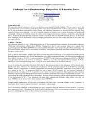
processes used <strong>for</strong> packaging silicon is the face-down wire-bond µBGA ® . The technology enables the smallest possible<br />
finished package outline while providing a method <strong>for</strong> furnishing a uni<strong>for</strong>m contact size. Although the use of the<br />
methodology requires a licensing agreement with the patent holder, the material set used in the package process significantly<br />
contributes to the physical integrity of the end product (illustrated in Figure 2).<br />
Source: Tessera<br />
Figure 2. Face-down DSBGA with through-slot wire bond interconnect<br />
The µBGA package methodology was developed to minimize the impact of the thermal coefficient of expansion between the<br />
silicon die element <strong>and</strong> the circuit board.
As originally published in the <strong>IPC</strong> APEX EXPO Proceedings.<br />
When completed, the structure provides a unique compliant polymer adhesive layer between the die surface <strong>and</strong> package<br />
substrate to decouple the differential expansion of the silicon (3ppm per ºC) from that of the circuit board substrate (~16ppm<br />
per ºC). The package, when mounted to the circuit board, does not require underfill.<br />
High Density Circuit Routing<br />
Board design <strong>for</strong> WLBGA <strong>and</strong> DSBGA is similar to that presently used <strong>for</strong> soldered surface mount assembly, however,<br />
l<strong>and</strong> pattern sizes will shrink <strong>and</strong> circuit density will likely increase. To provide the per<strong>for</strong>mance <strong>and</strong> interconnection<br />
capability needed <strong>for</strong> flip-chip <strong>and</strong> chip-scale IC packaging it will require adapting higher density circuit board<br />
fabrication technology. For the uncased die, <strong>for</strong> example, the contact sites are typically designed <strong>for</strong> wire-bond<br />
processing <strong>and</strong> are often r<strong>and</strong>omly spaced at the die periphery <strong>and</strong> will also be a great deal smaller than those used <strong>for</strong><br />
array packaged ICs (the die element with 100 micron pitch peripheral configured bond sites will likely have a pad size<br />
of 50 x 50 microns). Arrays configured devices, on the other h<strong>and</strong>, are generally more uni<strong>for</strong>m <strong>and</strong> can be configured<br />
with a much larger contact geometry <strong>and</strong> wider spacing between contact features. When establishing the array <strong>for</strong>mat<br />
the package designers will first consider a contact pitch that can be efficiently routed on the circuit board. In addition to<br />
the basic electrical connections, several bump contacts may be added <strong>for</strong> heat dissipation, mechanical support<br />
(outriggers, chip orientation, or future design migration). To enhance per<strong>for</strong>mance, the package designer may determine<br />
that the product will need redundant bump contacts <strong>for</strong> power, ground <strong>and</strong> critical signals. The actual number of bump<br />
or ball contacts needed varies with electrical, thermal, <strong>and</strong> mechanical requirements.<br />
After establishing the l<strong>and</strong> pattern array it‟s up to the PCB design specialist to plan optimum component placement <strong>and</strong><br />
alternative circuit routing strategies. Two fabrication methodologies can be considered; the more traditional drilled <strong>and</strong> plated<br />
via hole fabrication process or the use of micro-via-in-l<strong>and</strong> build-up board technology. Signal routing on subsurface layers of<br />
the drilled via PCB will be restricted by the space reserved between via pad sites. Adding more circuit layers can enable<br />
higher component density but, the added layers may increase the thickness of the substrate <strong>and</strong> extend fabrication<br />
complexity. On the other h<strong>and</strong>, finer circuit lines <strong>and</strong> spaces, although reducing the need <strong>for</strong> added circuit layers, may prove<br />
to be more costly due to the lower fabrication yield. As the pin count increases on smaller array packages, it may be<br />
necessary to move away from the conventional drilled-hole multilayer PCB fabrication technology to more advanced<br />
fabrication technologies. To maximize the efficiency of the circuit structure surface, the designer may consider build-up<br />
fabrication, moving the via-hole onto the l<strong>and</strong> pattern <strong>for</strong> more efficient subsurface circuit routing. The blind plated micro-via<br />
within the l<strong>and</strong> pattern can provide circuit routing density that is far greater than that possible with conventional drilledthrough-hole<br />
fabrication alone.<br />
The micro-via plated hole typically interconnects only component l<strong>and</strong> patterns on the outer surface circuit layer to one or<br />
more subsurface circuit layers. The build-up of high density circuit layers with laser drilled <strong>and</strong> plated micro-vias <strong>for</strong> layerto-layer<br />
interconnect (typical of that illustrated in Figure 3) enables the developer to maximize circuit density <strong>and</strong><br />
per<strong>for</strong>mance while reducing circuit layers <strong>and</strong> minimizing overall product or module size.<br />
Figure 3. Ten layer (3+4+3) build-up substrate example.<br />
Source: <strong>IPC</strong>-7094<br />
The micro-via hole-in-l<strong>and</strong> can be, <strong>and</strong> most often is, much smaller than the conventional mechanically drilled <strong>and</strong> plated<br />
through-hole via. Moving the via hole onto the l<strong>and</strong> pattern enables much closer component spacing <strong>and</strong> the smaller size hole<br />
allows significantly greater circuit routing channels on the inner layers of the circuit structure.<br />
L<strong>and</strong> Pattern Planning<br />
After establishing the contact type (ball or bump) <strong>and</strong> diameter, the supplier will determine the appropriate contact feature<br />
geometry <strong>and</strong> pitch.
As originally published in the <strong>IPC</strong> APEX EXPO Proceedings.<br />
Although the l<strong>and</strong> patterns developed <strong>for</strong> spherical (ball) contacts can be the same diameter as the sphere, experts recommend<br />
a l<strong>and</strong> diameter that is slightly smaller, however, with lower profile „bump‟ contacts, the l<strong>and</strong> pattern diameter is more likely<br />
to be the same as the bump diameter. Because there is little time <strong>for</strong> the user to build, test <strong>and</strong> evaluate l<strong>and</strong> pattern variations<br />
<strong>for</strong> each device, JEDEC has stated that the IC supplier is obligated to specify the recommended l<strong>and</strong> pattern geometry that<br />
will furnish the most satisfactory electrical interface between the device <strong>and</strong> package interposer or module substrate.<br />
The printed board l<strong>and</strong> pattern <strong>for</strong> flip-chips <strong>and</strong> die size array packages is simply a circle of coated copper foil whose<br />
diameter is the same or slightly smaller than the bump or ball contact diameter. Table 2 compares variations of contact<br />
features recommended in <strong>IPC</strong>-7094.<br />
Table 2: Contact pitch, ball size to l<strong>and</strong> pattern approximation (microns)<br />
Source: <strong>IPC</strong>-7094<br />
The requirements <strong>for</strong> design <strong>and</strong> the fabrication options used to develop circuit board substrates are well defined in <strong>IPC</strong>-2221.<br />
In addition, when the core material reflects requirements identified in the sectional st<strong>and</strong>ards; <strong>IPC</strong>-2222, <strong>IPC</strong>-2223, <strong>IPC</strong>-2224,<br />
<strong>IPC</strong>-2225 <strong>and</strong> <strong>IPC</strong>-2226 (the <strong>IPC</strong>-2226 is specifically targeted <strong>for</strong> high-density interconnect applications). The st<strong>and</strong>ard<br />
series provide recommendations <strong>for</strong> signal, power, ground <strong>and</strong> mixed distribution layers, dielectric separation, via <strong>for</strong>mation<br />
<strong>and</strong> metallization requirements <strong>and</strong> other design features that are necessary <strong>for</strong> HDI <strong>and</strong> advanced IC interconnection<br />
substrates including trade-off analyses required to match the mounting structure to the selected chip set. While lithography<br />
technologies establish the general limitations <strong>for</strong> circuit feature sizes, each of the various types of substrate has slightly<br />
different limits based on their construction <strong>and</strong> each has it own strengths <strong>and</strong> weaknesses in terms of layering <strong>and</strong> drilling.<br />
Table 3 lists three key characteristics of today‟s electronic package <strong>and</strong> module substrates <strong>and</strong> identifies the current status <strong>for</strong><br />
high volume manufacturing capability around the globe.<br />
Table 3: Substrate <strong>Design</strong> Feature Characteristics<br />
DESIGN FEATURES CONVENTIONAL LEADING EDGE STATE-OF-THE-ART<br />
Lines & Spaces (m) 100 - 250 50 – 100 < 25<br />
Via Diameter (m; as drilled) >250 100 - 200 50<br />
(Conductive) Layer Count 2 - 6 8 - 20 >20<br />
Dielectric Thickness (m) 25 - 100 12 -25 12<br />
Conductor Thickness (m) 18 -36 10 -17 8 - 9<br />
Adhesive Yes Adhesiveless Adhesiveless<br />
Minimum Annular Ring =(pad diameterhole<br />
diameter) x 1/2 (m)<br />
200 50 None<br />
(l<strong>and</strong>less via)<br />
Source: <strong>IPC</strong> Industry Roadmap<br />
<strong>Design</strong> <strong>for</strong> Assembly Processing<br />
As noted, PCB design <strong>for</strong> WLBGA <strong>and</strong> DSBGA assembly is similar to that <strong>for</strong> presently used <strong>for</strong> soldered surface mount<br />
assembly except, in some specialized applications the WLBGA die may adapt a non-solder process <strong>for</strong> attachment.
As originally published in the <strong>IPC</strong> APEX EXPO Proceedings.<br />
Key issues that need to be established <strong>for</strong> device mounting during the design planning phase of the substrate or module<br />
development are:<br />
<br />
<br />
<br />
<br />
<br />
<br />
L<strong>and</strong> pattern geometry<br />
Solder mask material, clearances<br />
Surface plating compatibility <strong>for</strong> attachment<br />
Clearance required <strong>for</strong> mounting, inspection<br />
Assembly test method, test feature requirement<br />
Thermal management, heat dissipation<br />
To accommodate precise registration of the stencil <strong>for</strong> solder paste printing <strong>and</strong> ensure accurate component placement, some<br />
means of vision or camera assisted alignment is required. Features needed <strong>for</strong> accurate positional reference on the PCB<br />
surface are fiducial targets. Both global <strong>and</strong> local fiducial targets are needed to enable assembly process efficiency. The<br />
globally located fiducial targets are used <strong>for</strong> both precise stencil-to-board alignment ensuring accurate solder paste print<br />
registration <strong>and</strong>, in subsequent process steps, to assist in the placement of both passive <strong>and</strong> active surface mount devices.<br />
When smaller boards are furnished in a panel <strong>for</strong>mat, three fiducial targets are recommended near the edge of the panel. The<br />
example furnished in the <strong>IPC</strong>-7094 document recommends the establishment one fiducial in the corner area of the PCB unit<br />
as a 0-0 reference with two additional fiducial targets extended outward at a 90 angle in the X <strong>and</strong> Y directions. These targets<br />
are used to enable more precise automated device placement by correcting offsets (X <strong>and</strong> Y position) <strong>and</strong> rotational offsets<br />
(theta position). In addition, one or preferably two targets are to be provided within the mounting zone <strong>for</strong> fine-pitch devices.<br />
Additional „zonal‟ fiducial target features may be required on larger boards having exceptionally high quantities of passive<br />
<strong>and</strong> active devices. A common fiducial size is preferred at all locations, although shape <strong>and</strong> size can be customized <strong>for</strong> unique<br />
applications. The Surface Mount Equipment Manufacturers Association (SMEMA) members, however, have agreed <strong>and</strong><br />
recommend the use of a 1.0mm (.040”) diameter solid l<strong>and</strong>. The fiducial surface may be plated or non-plated <strong>and</strong> they must<br />
be relatively flat <strong>and</strong> free of solder mask to ensure that the camera can make a quick identification.<br />
Additionally, palletizing smaller <strong>and</strong>/or odd shaped circuit boards is a common technique used to improve assembly<br />
efficiency. To accommodate de-paneling <strong>and</strong> electrical testing, each board unit within the panel should be furnished with a<br />
minimum of two tooling holes (preferably in diagonal corners). The hole size is typically defined by the assembly specialist<br />
(0.65 mm diameter is common) <strong>and</strong> they should be specified to be free of plating to ensure a more precise finished hole<br />
diameter.<br />
Conclusion<br />
Feature sizes <strong>for</strong> WLBGA <strong>and</strong> DSBGA packages will continue to shrink as the silicon fabrication technology adopts<br />
significantly higher circuit densities. This trend will allow the IC designer to further compress the functionality onto even<br />
smaller die outlines. To maintain the minimal finished package outline it will be necessary to reduce the contact size <strong>and</strong><br />
move the contact features closer together. We can expect the next generation of these components to push the limits of<br />
printed circuit fabrication capability. In preparation <strong>for</strong> higher density circuit boards, designers <strong>and</strong> suppliers will need to<br />
work together in selecting the best laminate materials <strong>and</strong> adopt more advanced fabrication processes. Even today, the higher<br />
density circuit routing <strong>and</strong> contact features are very near the size of early semiconductor technology, prompting circuit<br />
fabrication specialist to employ more sophisticated clean-room enclosures around key processes. For example, any<br />
microscopic particles at any stage of the circuit fabrication environment will have the potential to cause fatal defects. The<br />
photo-lithographic process steps in particular <strong>and</strong> the preparation steps leading up to the process are particularly vulnerable to<br />
particle contamination. Additionally, surface contamination or incompatible surface finish on the substrate is a concern<br />
because they can potentially contribute to product failure. In regard to market acceptance <strong>and</strong> per<strong>for</strong>mance of WLBGA <strong>and</strong><br />
DSBGA technology, there remain significant challenges that need to be addressed:<br />
<br />
<br />
<br />
<br />
<br />
Aggressive cost reduction strategies<br />
Consistency of die level quality<br />
Refining wafer <strong>and</strong> component level test capability<br />
PCB design analysis <strong>and</strong> assembly modeling capabilities<br />
Reliability improvement strategies<br />
In regard to package <strong>and</strong> module assembly, there will be an ongoing need <strong>for</strong> the OEM or EMS provider to make<br />
capital improvements to their facility. Improvements in the <strong>for</strong>m of a cleaner environment <strong>for</strong> each process <strong>and</strong><br />
significantly greater accuracy in solder printing, device placement <strong>and</strong> solder process control.
As originally published in the <strong>IPC</strong> APEX EXPO Proceedings.<br />
References:<br />
1. <strong>IPC</strong>-7094, „<strong>Design</strong> <strong>and</strong> Assembly Process Implementation <strong>for</strong> <strong>Flip</strong>-<strong>Chip</strong> <strong>and</strong> Die <strong>Size</strong> Components’<br />
2. <strong>IPC</strong>-2220, ‘<strong>Design</strong> St<strong>and</strong>ard Series including <strong>IPC</strong>-2221, <strong>IPC</strong>-2222, <strong>IPC</strong>-2223 <strong>and</strong> <strong>IPC</strong>-2225’<br />
3. <strong>IPC</strong>-2226, ‘<strong>Design</strong> St<strong>and</strong>ard <strong>for</strong> High Density Interconnect (HDI) Printed Boards’<br />
4. JEDEC Publication 95 Section 4.7,‟Die-<strong>Size</strong> Ball Grid Array <strong>Package</strong> (DSBGA’)<br />
5. JEDEC Publication 95 Section 4.18, „Wafer Level Ball Grid Arrays (WLBGA)’<br />
Solberg Technical Consulting, Madison Wisconsin<br />
Telephone: 608-224-4220 or 408-568-3734<br />
e-mail: vsolberg123@aol.com