Tutorial: Magic Tee Coupler - Empire
Tutorial: Magic Tee Coupler - Empire Tutorial: Magic Tee Coupler - Empire
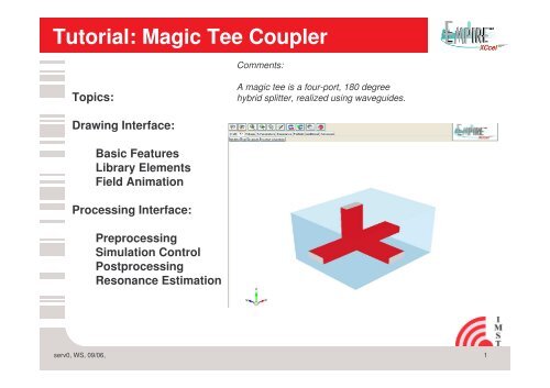
Tutorial: Magic Tee Coupler Comments: Topics: A magic tee is a four-port, 180 degree hybrid splitter, realized using waveguides. Drawing Interface: Basic Features Library Elements Field Animation Processing Interface: Preprocessing Simulation Control Postprocessing Resonance Estimation serv0, WS, 09/06, 1
- Page 2 and 3: Step 1 : Template Wizard 1. Start E
- Page 4 and 5: Step 3: Definition of Waveguide 1.
- Page 6 and 7: Step 5: Port Definition 1. Create a
- Page 8 and 9: Step 7: Field Dump Box 1. Create la
- Page 10: Step 9: 1. Create a layer for field
<strong>Tutorial</strong>: <strong>Magic</strong> <strong>Tee</strong> <strong>Coupler</strong><br />
Comments:<br />
Topics:<br />
A magic tee is a four-port, 180 degree<br />
hybrid splitter, realized using waveguides.<br />
Drawing Interface:<br />
Basic Features<br />
Library Elements<br />
Field Animation<br />
Processing Interface:<br />
Preprocessing<br />
Simulation Control<br />
Postprocessing<br />
Resonance Estimation<br />
serv0, WS, 09/06,<br />
1
Step 1 : Template Wizard<br />
1. Start <strong>Empire</strong> XCcel<br />
2. Click on Start From Scratch<br />
serv0, WS, 09/06,<br />
2
Step 2: Definition of Metal Block<br />
1. Create a new layer and name it<br />
as `Metal´<br />
2. Select + Structure +Create+Box<br />
x0=0 ; x1=250000<br />
y0=0 ; y1=200000<br />
z0=0 ; z1=150000<br />
serv0, WS, 09/06,<br />
3
Step 3: Definition of Waveguide<br />
1. Create a layer with<br />
dielectric<br />
properties and<br />
name it as<br />
´wg-Air´<br />
2. Set the priority of<br />
this layer to be the<br />
highest<br />
3. Now create three<br />
different Boxes in a<br />
T-shape with inner<br />
dimensions as<br />
shown in the figure<br />
4. For Details See<br />
Next Page<br />
serv0, WS, 09/06,<br />
4
Step 4: Setup of Waveguide<br />
1. Select ‘wg-Air‘ as the current layer<br />
2. Select +Create +Box<br />
x0=0 ; x1=250000<br />
y0=100000 ; y1=150000<br />
z0=30000 ; z1=50000<br />
3. Select +Create +Box<br />
x0=100000 ; x1=150000<br />
y0=100000 ; y1=0<br />
z0=30000 ; z1=50000<br />
4. Select +Create +Box<br />
x0=115000 ; x1=135000<br />
y0=150000 ; y1=100000<br />
z0=50000 ; z1=150000<br />
Box Creation Editor<br />
serv0, WS, 09/06,<br />
5
Step 5: Port Definition<br />
1. Create a new layer and name it<br />
ports and delete its properties<br />
2. Create Boxes at the four open<br />
ends of the waveguide and assign<br />
Waveguide property and port<br />
number to each of these boxes<br />
3. For Details See Next Page<br />
Comments:<br />
Coordinates may be entered by<br />
values or mouse input<br />
serv0, WS, 09/06,<br />
6
Step 6 :Port Definition(Co-ordinates)<br />
1. Port1: (Excite only this particular port by entering its<br />
start and end Excitation Port Number.)<br />
x0=100000 ; x1=150000<br />
y0=500 ; y1=-500<br />
z0=30000 ; z1=50000<br />
2. Port2:<br />
x0=249500 ; x1=250500<br />
y0=150000 ; y1=100000<br />
z0=30000 ; z1=50000<br />
3. Port3:<br />
x0=-500 ; x1=500<br />
y0=150000 ; y1=100000<br />
z0=30000 ; z1=50000<br />
4. Port4:<br />
x0=115000 ; x1=135000<br />
y0=150000 ; y1=100000<br />
z0=149500 ; z1=150500<br />
serv0, WS, 09/06,<br />
7
Step 7: Field Dump Box<br />
1. Create layer field-dump<br />
2. Change the layer property to<br />
- dumpbox<br />
- field<br />
- field distribution<br />
+ Add Sequence 3.5 to 5.5GHz<br />
with for e.g. 5 sampling<br />
points or as desired<br />
3. Select +Create +Box<br />
x0=-5000 ; x1=255000<br />
y0=205000 ; y1=-4500<br />
z0=-5000 ; z1=155000<br />
serv0, WS, 09/06,<br />
8
Step 8:Simulate the <strong>Magic</strong> <strong>Tee</strong> <strong>Coupler</strong><br />
1. Click Start Simulation<br />
and view the results on screen<br />
as the simulation is running.<br />
Voltage<br />
S-Parameters<br />
serv0, WS, 09/06,<br />
9
Step 9:<br />
1. Create a layer for field display<br />
and name it as field-display<br />
2. Change Object Property<br />
- Field<br />
- Field Display<br />
- 3D Field Animation Box<br />
- Entired desired frequency<br />
3. Create Boxes along the T-joint of<br />
the <strong>Magic</strong> <strong>Tee</strong> in the respective<br />
layers and<br />
4. Now Switch to the 3D-Mode to<br />
visualize the fields<br />
Field Animation in 3D-Mode:<br />
serv0, WS, 09/06,<br />
10


