Pike Technologies Comprehensive Catalog of FTIR ... - Madatec
Pike Technologies Comprehensive Catalog of FTIR ... - Madatec
Pike Technologies Comprehensive Catalog of FTIR ... - Madatec

Create successful ePaper yourself
Turn your PDF publications into a flip-book with our unique Google optimized e-Paper software.
P IKE T ECHNOLOGIES WWW. PIKETECH. COM 608-274-2721<br />
The optical material substrate used to create the polarizers<br />
determines the wavelength range <strong>of</strong> the polarizer – such as ZnSe<br />
or KRS-5. Table 1 shows the K 1 values <strong>of</strong> PIKE <strong>Technologies</strong> polarizers.<br />
The maximum transmitted light is affected by the transmission <strong>of</strong><br />
the materials and the scattering <strong>of</strong> the ruled and evaporated surfaces.<br />
Fresnel losses are determined by the refractive index and<br />
the performance <strong>of</strong> the anti-reflection coating on the element. The<br />
maximum transmission compared to a fully depolarized open<br />
beam is typically less than 50%. However, <strong>FTIR</strong> spectrometers<br />
produce slightly polarized beams, which in most cases are oriented<br />
in the vertical direction in the sample compartment. Thus the<br />
apparent transmission <strong>of</strong> a single polarizer oriented vertically<br />
and compared to open beam can be over 50%.<br />
The other critical parameter <strong>of</strong> polarizers, the contrast, can<br />
be measured by crossing two polarizers and recording the<br />
throughput signal. For efficient polarizers in a practical spectroscopy<br />
setting, such as using a converging infrared beam in the sample<br />
compartment <strong>of</strong> an <strong>FTIR</strong> spectrometer, it is expected that the<br />
light level should be less than 1%. For selected high performance<br />
polarizers it can be better than 0.5%.<br />
Polarizers are usually mounted in a plastic disc and placed<br />
in a rotating holder with an angle scale. This way, the angle <strong>of</strong><br />
the polarizer orientation can be positioned with approximately<br />
1 degree repeatability. Motorized polarizers are available with<br />
much better angular accuracy and precision. The automated<br />
polarizers are also very useful for conducting a series <strong>of</strong> experiments<br />
with different angle settings under complete computer control.<br />
One <strong>of</strong> the main uses <strong>of</strong> infrared polarizers is to monitor<br />
molecular orientation in samples such as films and fibers. During<br />
manufacture polymers tend to orient along the axis <strong>of</strong> the<br />
mechanical stretching and this preferred orientation is retained<br />
after the material stops flowing. In some cases, polymers are a<br />
mixture <strong>of</strong> crystalline, more polarized, and amorphous, less<br />
polarized, forms <strong>of</strong> the material. In order to study orientation,<br />
polarized light is directed on the film or fiber. The polarized light<br />
electrical vector coinciding with the dipole <strong>of</strong> the infrared active<br />
moiety increases in absorption intensity, thereby revealing the<br />
band assignment and the orientation <strong>of</strong> the molecular group.<br />
Single crystals placed in the focus <strong>of</strong> polarized light also absorb<br />
selectively, depending on the orientation <strong>of</strong> the crystal.<br />
Polarizers can also be used in conjunction with attenuated<br />
total reflection (ATR). Even without polarizers, for any ATR that<br />
retains the orientation relative to the incoming infrared beam,<br />
there could be spectral differences noted when an oriented sample<br />
is placed with its direction along the optical axis or perpendicular<br />
to it. The phenomenon is related to penetration depth differences<br />
for the light components polarized parallel or perpendicular with<br />
the reflective surface (see ATR Theory and Applications).<br />
Another important application <strong>of</strong> polarizers is the enhancement<br />
<strong>of</strong> the signal measuring thin films on polished semiconductors,<br />
metallic mirrors and other reflective surfaces.<br />
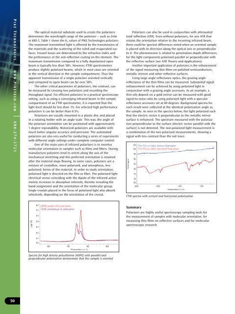
Using large angle reflectance optics, the grazing angle<br />
reflectance <strong>of</strong> the thin films can be measured. Substantial signal<br />
enhancement can be achieved by using polarized light in<br />
conjunction with a grazing angle accessory. As an example, a<br />
thin oily deposit on a gold mirror can be measured with good<br />
signal-to-noise ratio by using polarized light with a specular<br />
reflectance accessory set at 80 degrees. Background spectra for<br />
each result were collected at the identical polarization angle as<br />
the sample. As seen in the spectra below, the light polarized such<br />
that the electric vector is perpendicular to the metallic mirror<br />
surface is enhanced. The spectrum measured with the polarization<br />
perpendicular to the surface (electric vector parallel with the<br />
surface) is not detected. The non-polarized light measurement is<br />
a combination <strong>of</strong> the two polarized measurements, showing a<br />
signal with less contrast than the red trace.<br />
<strong>FTIR</strong> spectra with vertical and horizontal polarization<br />
Summary<br />
Polarizers are highly useful spectroscopy sampling tools for<br />
the measurement <strong>of</strong> samples with molecular orientation, for<br />
measuring thin films on reflective surfaces and for molecular<br />
spectroscopic research.<br />
Spectra for high density polyethylene (HDPE) with parallel and<br />
perpendicular polarization demonstrate that this sample is oriented<br />
50