T2800 Data Sheet - DSL electronic ® GmbH
T2800 Data Sheet - DSL electronic ® GmbH
T2800 Data Sheet - DSL electronic ® GmbH

You also want an ePaper? Increase the reach of your titles
YUMPU automatically turns print PDFs into web optimized ePapers that Google loves.
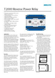
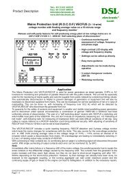
<strong>T2800</strong> Overcurrent or Earth Fault Relay<br />
• Protection of generators against earth<br />
faults or overcurrent<br />
• Visual indication of power, pick-up<br />
and relay tripping<br />
• Wide range of settings for current and<br />
delay, both in two steps.<br />
• High precision digital countdown<br />
timer for delayed output<br />
• Accepts high supply voltage<br />
variations: 60 - 110%<br />
• Cost effective and highly reliable<br />
compact design<br />
• 50 hours burn-in before final test<br />
• Operating temperature range:<br />
-20°C to +70°C<br />
• Flame retardant enclosure<br />
• DIN rail or screw mounting<br />
Application<br />
The <strong>T2800</strong> Overcurrent or Earth Fault<br />
Relay has a broad application as an earth<br />
fault or a single phase overcurrent detection<br />
relay. It has a wide setting range for<br />
protection, control and monitoring.<br />
The <strong>T2800</strong> is part of the SELCO T-Line<br />
series with modular units for protection,<br />
control and monitoring of generators.<br />
Function<br />
The <strong>T2800</strong> detects the magnitude of the<br />
current and, if this exceeds the preset<br />
level (0.02 - 2 x I N<br />
), the pick-up LED will<br />
indicate and the delay timer will be<br />
started.<br />
After the preset time (0.1 - 10 sec.) has<br />
expired the output relay and the<br />
corresponding LED will be activated,<br />
provided that the current level was<br />
exceeded for the entire delay time.<br />
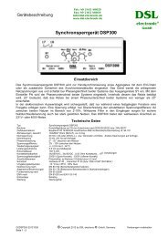
The <strong>T2800</strong> has a normally energized<br />
output relay. The relay is a latching<br />
relay which can be reset or disabled.<br />
The latching of the output relays is reset<br />
or disabled by bridging terminals 15<br />
and 16.<br />
The current setting range (0.02 – 0.2 x I N<br />
)<br />
is multiplied by 10 (0.2 – 2.0 x I N<br />
) by<br />
bridging terminals 18 and 19.<br />
The delay setting range (0.1 – 1.0 sec.) is<br />
multiplied by 10 (1.0 - 10 sec.) by<br />
bridging terminals 12 and 13.<br />
The current setting can be calculated<br />
according to the following example:<br />
Overcurrent protection of a generator.<br />
Required trip level: 110%<br />
Generator rating: 695A<br />
Current transformer: 800/5A<br />
Setting: 110 x 695/800 = 96% = 0.96 x I N<br />
Troubleshooting<br />
1) If the relay is not operating please<br />
check that the power LED is on,<br />
ensuring that the supply is present.<br />
2) Measure the supply voltage which<br />
must be compatible with the<br />
information label on top of the<br />
enclosure.<br />
3) Measure the current levels in<br />
erminals 5 and 6 and check that the<br />
current is above setting.<br />
For example:<br />
0.08 x I N<br />
= 0.4A; 1 x I N<br />
= 5A<br />
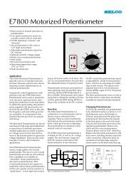
Installation<br />
The supply voltage is connected to<br />
terminals 1 and 3 or terminals 2 and 3,<br />
according to the supply source.<br />
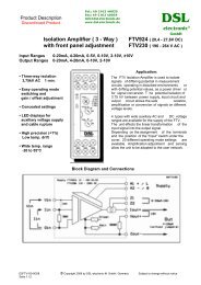
The <strong>T2800</strong> is connected to the measuring<br />
current coming from the current<br />
transducer(s) secondary via terminals<br />
5 and 6. See application diagram.<br />
Fig. 1. Application. Earth fault detection and overcurrent detection using same transducers
Specifications<br />
<strong>T2800</strong> Overcurrent or Earth Fault Relay<br />
50<br />
10<br />
7.5<br />
Dimensions.<br />
100<br />
Fixing holes<br />
2 x ø 4.5 mm<br />
85<br />
115<br />
Dimensions in mm<br />
70<br />
Type Approvals and Certificates<br />
The <strong>T2800</strong> has been designed and tested<br />
for use in harsh environments. The<br />
unit is based on standard components,<br />
providing long term durability.<br />
The <strong>T2800</strong> carries the CE label and has<br />
been approved by the following marine<br />
classification societies:<br />
Bureau Veritas<br />
Russian Maritime Register of Shipping<br />
Trip level<br />
Delay<br />
Max. voltage<br />
0.02 - 0.2 x I N<br />
or 0.2 - 2 x I N<br />
0.1 - 1.0 sec. or 1.0 - 10 sec.<br />
660V<br />
Voltage range 60 - 110%<br />
Consumption<br />
Continuous current<br />
Frequency range<br />
Output relay<br />
Contact rating<br />
Overall accuracy ±5%<br />
Repeatability ±1%<br />
Operating temperature<br />
Dielectric test<br />
EMC<br />
Burn-in<br />
Enclosure material<br />
Weight<br />
Voltage 5VA at U N<br />
Current 0.3VA at I N<br />
2 x I N<br />
45 - 400Hz<br />
Normally energized, latching, resetable<br />
AC: 400V, 5A, 2000VA<br />
DC: 150V, 5A, 150W<br />
-20°C to +70°C<br />
2500V, 50Hz<br />
CE according to EN50081-1, EN50082-1, EN50081-2,<br />
EN50082-2<br />
50 hours before final test<br />
Polycarbonate. Flame retardant<br />
0.5kg<br />
Dimensions 70 x 100 x 115mm (H x W x D)<br />
Installation<br />
35mm DIN rail or 4mm (3/16”) screws<br />
The specifications are subject to change without notice.<br />
Type Selection Table<br />
Standard types: I N<br />
= 5A<br />
Terminals<br />
Type 1-3 2-3 I N<br />
<strong>T2800</strong>-00 230V 5A<br />
<strong>T2800</strong>-01 450V 400V 5A<br />
<strong>T2800</strong>-02 127V 120V 5A<br />
<strong>T2800</strong>-04 24V DC+AC 5A<br />
<strong>T2800</strong>-05 480V 415V 5A<br />
<strong>T2800</strong>-08 230V 1A<br />
Other combinations and voltages are available on request.<br />
Main office:<br />
SELCO A/S<br />
Betonvej 10<br />
DK-4000 Roskilde<br />
Denmark<br />
Phone: + 45 7026 1122<br />
Fax: + 45 7026 2522<br />
e-mail: selco.dk@selco.com<br />
www.selco.com<br />
12 1<br />
SEC x 10<br />
13<br />
2<br />
3<br />
15 LATCHING<br />
16 OFF<br />
18<br />
I x 10<br />
19 N<br />
7<br />
8<br />
9 5<br />
10 6<br />
Fig. 2. Relay shown deenergized<br />
T289562E