4600 IOM - Eastech Flow Controls
4600 IOM - Eastech Flow Controls
4600 IOM - Eastech Flow Controls

Create successful ePaper yourself
Turn your PDF publications into a flip-book with our unique Google optimized e-Paper software.
SCOPE<br />
This manual contains information concerning the installation, operation and<br />
maintenance of the Vantage 4000. To ensure proper performance of the unit, the<br />
instructions should be thoroughly understood and followed.<br />
Section<br />
1<br />
Keep the manual in a readily accessible location for future reference.<br />
Changes and additions to the original edition of this manual will be covered by a “CHANGE<br />
NOTICE” supplied with the manual. The change notice will identify the sections in this manual<br />
where the changes have occurred.<br />
Vantage 4000<br />
Table of Contents<br />
Scope ...................................................................................................................................... 1-1<br />
General Specifications............................................................................................................ 1-2<br />
Installation Procedure.......................................................................................................... 2-1<br />
Enclosure Mounting ............................................................................................................... 2-1<br />
System Diagram ..................................................................................................................... 2-2<br />
Wiring Connections................................................................................................................ 2-3<br />
Splice Procedure..................................................................................................................... 2-5<br />
Programming........................................................................................................................ 3-1<br />
QuikCal Menu Functions ....................................................................................................... 3-1<br />
Main <strong>Flow</strong> Screen.............................................................................................................. 3-2<br />
Review Meter..................................................................................................................... 3-2<br />
Program ............................................................................................................................. 3-2<br />
Measure Units .................................................................................................................. 3-2<br />
Sensor Install.................................................................................................................... 3-3<br />
Totalizer........................................................................................................................... 3-5<br />
4-20 Output...................................................................................................................... 3-6<br />
Damping........................................................................................................................... 3-6<br />
Lost Signal ....................................................................................................................... 3-7<br />
<strong>Flow</strong> Simulation............................................................................................................... 3-7<br />
Integrator.......................................................................................................................... 3-7<br />
Setpoints........................................................................................................................... 3-8<br />
Relays............................................................................................................................... 3-8<br />
Daily Sum........................................................................................................................... 3-8<br />
Data Logger ....................................................................................................................... 3-9<br />
System Setup...................................................................................................................... 3-9<br />
Vantage 4000 1-1 942000<br />
01/04
GENERAL SPECIFICATIONS<br />
Pipe Size Range<br />
Output<br />
Display<br />
Programming<br />
Power<br />
Strap On Sensors: 1” to 120” (Larger pipe ranges available, consult factory)<br />
Hotshot Style Sensors: 8” to 120” (using tapping saddles >15”)<br />
Windowed Spool Sensors: 3”to 48”<br />
Internal Wetted Sensors: 12” to 120”<br />
Two 4-20 mADC isolated; 800 ohms max. (Model <strong>4600</strong>)<br />
One 4-20 mADC isolated, 800 ohms max (Model 4400)<br />
Three programmable relays, SPDT .25 amp @ 120 VAC, .5 amp @ 24 VDC (Model <strong>4600</strong>)<br />
One programmable relay, SPDT .25 amp @ 120 VAC, .5 amp @ 24 VDC (Model 4400)<br />
RS-232 Serial Port, 9600 – 36500 Baud, Modbus Protocol<br />
RS-485 Serial Port optically isolated, Modbus Protocol (Model <strong>4600</strong> Only)<br />
12VDC, 100ma Maximum<br />
Data Logger & Software CD<br />
Backlit LCD, 128x64 Graphic Module<br />
Front panel mounted 16 button keypad., Computer or Palm Pilot<br />
80/240 VAC, 50/60 Hz, or 12-28 VDC @ 350 mA continuous.<br />
Accuracy<br />
Sensor<br />
Electronic<br />
Enclosure<br />
Up to +/- 0.5% of actual flow above 1 foot per second.<br />
Strap On:<br />
Temperature Range: -20° to 160° F (-30° to 70° C)<br />
-20° to 300° F, High Temperature option<br />
Operating Frequency: 640 or 1280 KHz<br />
Housing:<br />
Cable:<br />
Hotshot Wetted:<br />
Temperature Range:<br />
Operating Frequency:<br />
Pressure:<br />
Housing:<br />
Cable:<br />
Anodized aluminum, Ultem plastic<br />
50 feet of Triaxial PVC coated Std.<br />
(1000 ft maximum) Belden 9222 or equal<br />
-40° to 160° F (-40° to 90° C) 30 kHz<br />
640 or 1280 KHz<br />
0-300 PSI<br />
316s/s, PVC tip<br />
50 feet of Triaxial PVC coated Std<br />
(1000 ft maximum) Belden 9222 or equal<br />
IP66/NEMA 4X standard, temperature range: -4° to 158° F (-20° to 70° C)<br />
Optional with heater, temperatures down to -40° F (-40°C)<br />
Vantage 4000 1-2
Section<br />
2<br />
Installation<br />
Enclosure Mounting<br />
The enclosure is rated IP 66 (NEMA 4X) and can be mounted indoors or out. A sunshade is recommended<br />
for outdoor installation. Openings used for the sensor and power must be properly prepared and sealed to<br />
maintain the rating. There are two stainless steel mounting brackets factory assembled to the enclosure. The<br />
mounting feet have slots for ¼" bolts (4 places).<br />
The electronics should be mounted with the display<br />
at eye level or lower. There are three ½" holes in<br />
the bottom of the enclosure for conduit fittings.<br />
9.32"<br />
8.25"<br />
8.92"<br />
9.50"<br />
5.50"<br />
These holes have rubber plugs installed at the<br />
factory. If you do not use all three holes for<br />
conduit, leave the rubber plugs in the holes to<br />
protect the enclosure ratings.<br />
Opening the Enclosure:<br />
There are two hinged door clasps on the front cover<br />
of the enclosure. To open, put thumb on one of the<br />
hinges, pull toward the outside of the enclosure.<br />
Once the hinge pops to the outside it will lower<br />
allowing the clasp at the bottom of the hinge to<br />
release. Swing the cover towards the front to open.<br />
The opposite side will act as a hinge to swing the<br />
door freely. To close, clasp the bottom side of the<br />
hinge and push the top of the hinge toward the<br />
enclosure until it locks.<br />
Hinge Lock and Optional Door Lock<br />
There are two plastic gray plugs supplied with the Vantage 4000. These plugs may be used to<br />
permanently disable one side of the hinged handles. If an optional door lock was supplied with the<br />
unit then one side of the hinge handle should be plugged and the other side will have the key lock<br />
used. Either side hinge handle may be disabled. Insert the gray plug into the keyhole. Warning:<br />
This will permanently disable the hinge handle. The other side can be used for the key provided<br />
for the optional lock.<br />
Vantage 4000 2-1
Note: The key will have to be left in the hinge handle<br />
if the door is to remain unlocked. The only way the<br />
key can be removed is if the hinge handle is locked.<br />
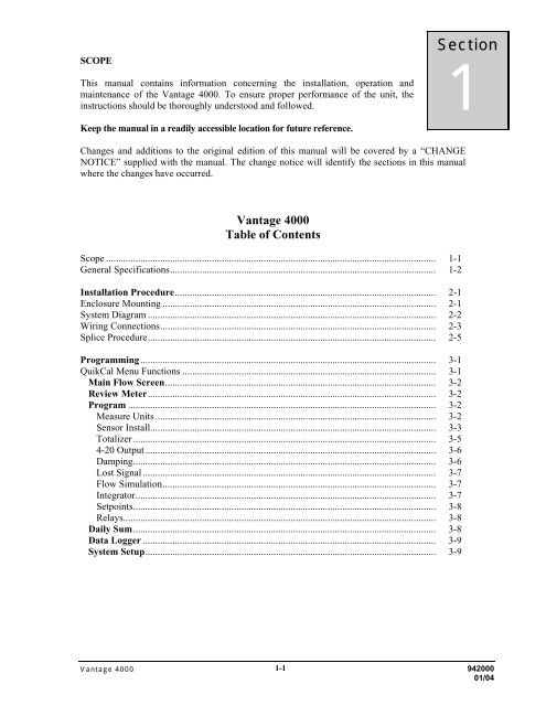
Vantage 4000 Recommended System Diagram<br />
NEMA 4X/IP66<br />
Enclosure<br />
Flex Conduit<br />
(by others)<br />
Pull Box<br />
(by others)<br />
Metallic Conduit<br />
(by others)<br />
Sensor Cable (1000ft max.)<br />
7/8" entrance holes<br />
(3 places)<br />
Input Power<br />
4-20madc output<br />
Sensor connections: 1/2"-14 NPT<br />
Vantage 4000 2-2
Wiring Diagram<br />
There are three terminal strips provided for all wiring of the Vantage 4000. The AC power terminal<br />
is separate from the other two terminal strips. The power terminal strip has three connections for<br />
High, Low and Ground for AC voltage only. Refer to the wiring diagram below for all internal<br />
wiring connections. The specifications for the load requirements for each input are on Page 1-2<br />
General Specifications. The unit may also be powered with 12-24 VDC at TBA Terminals 14 (+)<br />
and 15 (-).<br />
*Model <strong>4600</strong> Only<br />
SENSOR<br />
CONNECTIONS<br />
DC Power Out<br />
AMR<br />
+ - + -<br />
RS-232<br />
CTS<br />
RTS<br />
RX<br />
TX<br />
*<br />
RS-485<br />
B<br />
A<br />
GND<br />
Heater<br />
Connection<br />
B<br />
A<br />
UPSTREAM<br />
DOWNSTREAM<br />
1 2 3 4 5 6 7 8 9 10 11 12 13 14 15<br />
+ - + -<br />
+ -<br />
4-20maDc Out #1<br />
4-20maDc Out #2<br />
*<br />
NC<br />
C<br />
NO<br />
Relay #1<br />
NC<br />
C<br />
NO<br />
Relay #2<br />
NO<br />
NC<br />
C<br />
Relay #3<br />
* *<br />
Battery (DC) In<br />
LO<br />
HI<br />
GND<br />
TB1<br />
90-240VAC<br />
50/60 HZ<br />
Sensor Cable Preparation<br />
1-5/8" 1-3/4"<br />
1-1/4" 1-3/8"<br />
1-1/8" 1"<br />
3/4" 5/8"<br />
3/8" 1/2"<br />
1/4"<br />
3/8" 1/2"<br />
3/8"<br />
1/4"<br />
3/8"<br />
Remove<br />
outer<br />
cover<br />
Remove<br />
outer<br />
Remove<br />
middle<br />
Remove<br />
middle<br />
Remove<br />
inner<br />
Completed<br />
cable<br />
1 shield 2 cover 3 shield 4<br />
cover<br />
5 6<br />
Vantage 4000 2-3
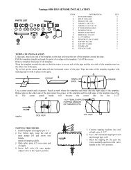
Sensor Cable Preparation<br />
Sensor cable connections. Before pulling the sensor cables through the conduit, mark the ends of the cables to<br />
indicate which is the upstream and downstream sensor cable. Leave approximately 8 inches of cable<br />
extending from the conduit in the enclosure. Prepare the cable ends in the following manner.<br />
1. Remove outer cable cover. Measure 1-5/8" from the end of the cable. With a cutting tool,<br />
carefully cut through the outer covering completely around the cable making sure not to cut into the<br />
outer shield. Make another cut from the first cut to the end of the cable and remove the outer cover.<br />
2. Remove outer shield. Measure 1-1/4" from the end of the cable with a pair of small cutters, cut<br />
the shield around the cable at the measured point and remove the cut off shield.<br />
3. Remove middle cover. Measure 1" from the end of the cable. With a cutting tool, carefully cut<br />
through the middle covering completely around the cable making sure not to cut into the middle<br />
shield. Make another cut from the first cut to the end of the cable and remove the middle cover.<br />
4. Remove middle shield. Measure 5/8" from the end of the cable. With a pair of small cutters, cut<br />
the shield around the cable at the measured point and remove the cut off shield.<br />
5. Remove inner cover. Measure 3/8" from the end of the cable. With a cutting tool or pair of wire<br />
strippers, carefully cut the inner covering completely around the cable, making sure not to cut into the<br />
center conductor and remove the inner cover.<br />
After the ends of the cables have been prepared, loosen the screws on the sensor inputs at the lower<br />
left corner of the PCB and remove the two pairs of clamps. Take the upstream cable and insert the<br />
center conductor into the top terminal of the upstream sensor and tighten the screw. Slightly pull on<br />
the cable to ensure the wire is secured to the terminal. Take the downstream cable and insert the<br />
center conductor into the top terminal of the downstream sensor and tighten the screw. Slightly pull<br />
on the cable to ensure the wire is secured to the terminal.<br />
Place the two pair of clamps over the middle and outer shields and secure them into place. Verify<br />
that the clamps are making good contact with the shields and that no wires of the shields are<br />
extending beyond their own clamp down area.<br />
Vantage 4000 2-4
Triax Cable Splice Procedure<br />
Materials Required<br />
* 4 pigtail cap crimps (wire size 18-12)<br />
* 2 center conductor cap crimps (wire size 22-14)<br />
* Strips of splice wrap<br />
Crimp tool (customer supplied)<br />
Knife (customer supplied)<br />
Pointed tool (customer supplied)<br />
Junction box (customer supplied)<br />
A cable connection kit may be purchased through <strong>Eastech</strong> Badger that will include the * items above<br />
(Part # 541874).<br />
Trim each of the four cables at the junction box to 9 inches in length. Each of the four cables can now be<br />
prepared as described in the sequence following:<br />
Using a knife, trim two inches of the outer jacket from each cable. The wire braid beneath the outer<br />
jacket must not be cut. See "A".<br />
Using a pointed tool, carefully comb out the outer braid of each cable as shown in "B". Form the combed<br />
braid into a pigtail dressed to the side of the cable as<br />
shown in "C".<br />
Trim 1 inch of the inner jacket from each of the cables<br />
as shown in "D". Again, use care not to cut the inner<br />
braid beneath the inner jacket.<br />
Using a pointed tool, carefully comb out the inner<br />
braid "E" and form into a pigtail dressed to the same side<br />
A B C D E F G<br />
of the cable as outer pigtail in "F".<br />
Remove 1/2 inch of insulation from the inner conductor of each cable. Cut the outer pigtail to the same<br />
length as the inner pigtail on each cable. "G" depicts the completed preparation.<br />
Cable Termination<br />
Pull cables approximately 18 inches outside of junction box. Select one sensor cable and one cable from<br />
the electronic enclosure and place them side by side as shown in Fig. 1. Twist each cable's outer pigtails<br />
together, then the inner pigtails together and finally the center<br />
conductors together to form the cable splice. In similar fashion,<br />
connect the remaining sensor cable and the cable from the<br />
electronic enclosure.<br />
Identification of upstream and downstream sensor cables must<br />
now be made. Connect a short wire from the center conductor<br />
splice to the inner shield pigtail splice on the upstream sensor<br />
FIG 1<br />
FIG 2<br />
cable. Using a multimeter determine the upstream sensor cable at<br />
the electronic enclosure end by continuity measurement. Identify the upstream cable for later termination.<br />
Remove the shorting wire and using the cap crimps supplied, crimp the larger caps on each spliced<br />
pigtail and the small cap on the center conductor splice as shown in Fig. 2. Repeat this procedure for the<br />
second cable.<br />
At this point turn power on at the electronics and verify that an OK signal condition appears on the<br />
display.<br />
Turn power "OFF".<br />
Using Splice Strips<br />
1. Remove cover off of strips<br />
2. Totally wrap strips tightly around all of the splice connections.<br />
The finished splices should be coiled inside the junction box. When properly placed, the splices should<br />
be clear of the junction box cover area. Proper sealing of the junction box is necessary for watertight<br />
integrity.<br />
This completes the triax cable splice connection.<br />
Vantage 4000 2-5
<strong>Flow</strong><br />
Vel.<br />
FwdT<br />
X1<br />
Status -<br />
MENU<br />
00 GPM<br />
00 FPS<br />
00 GAL<br />
Okay<br />
QuickCal Menu Functions<br />
The screen to the left represents the main screen. However, the<br />
user may select the desired lines to be displayed on the main<br />
screen. Programming of the main display will be explained later<br />
in the manual. To program, recalibrate or change any function<br />
in the Vantage 4000, press the “MENU” key. This will display<br />
the Main Menu for all of the functions of the Vantage 4000<br />
QuikCal firmware. Below is a quick reference for the main<br />
menu and a brief description of each to allow the user to<br />
navigate to the required locations.<br />
Section<br />
3<br />
>01) Review Meter Selection of this will display the application set up parameters and sensor orientation<br />
(V, Z and W shot)) and the sensor separation that the meter is programmed.<br />
>02) Program 01) Measure Units To assign engineering units for flow, velocity and<br />
measurement.<br />
02) Sensor Install To calibrate pipe parameters. (pipe size, pipe material &<br />
schedule, fluid, sensor type and mounting style (V, Z and W<br />
shot) and Sensor installed cable lengths.<br />
03) Totalizer To select totalizer engineering units and multiplier.<br />
04) 4-20 Outputs To adjust, assign and set full scale of the 4-20ma output and<br />
to assign low flow shutdown.<br />
05) Damping To adjust damping time.<br />
06) Lost Signal To adjust Lost signal time and Fail to zero or span.<br />
07) <strong>Flow</strong> Sim <strong>Flow</strong> simulation<br />
08) Integrator To assign closure for contact integrator.<br />
09) Setpoints To assign setpoints. (e.g. Hi or Lo alarms)<br />
10) Relays Relay assignment for all relays.<br />
11) Meter Factor Zero Offset Adjustments<br />
>03) Daily Sum 01) Daily Sum To review daily average, minimum and maximum<br />
parameters<br />
>04) Data logger 01) Set Time/date To set the time and date<br />
02) Storage Rate To set logger storage intervals.<br />
03) Secondary To set secondary trip point and time intervals.<br />
04) Log Channels To set channels to log and values to log.<br />
05) View Data To review logged channel history.<br />
06) Amount Stored To review time, amount of data stored and amount left.<br />
07) Clear Data To clear all stored logger data.<br />
>05) System Setup 01) Language To set unit to display language to be used.<br />
02) Display To set display contrast and backlighting.<br />
03) Comm. Ports To set RS-232 & 485 communications and baud rates.<br />
04) Display Modes To select display lines to be viewed on main screen.<br />
05) Options To select additional relays and Isolated 485.<br />
06) Totals Reset To reset the totalizer.<br />
07) New Password To change password.<br />
08) Summary Reset To clear daily summary.<br />
09) Sensor Option To set sensor power from Normal to High or to change<br />
polarity of sensors.<br />
10) Meter reset To reset to factory defaults.<br />
11) New Firmware To upload new firmware into meter.<br />
Vantage 4000 3-1
Main <strong>Flow</strong> Screen: The main flow screen will have four pages: Main <strong>Flow</strong> screen (to<br />
view flow and totals, Alarms Tripped screen (to review alarms tripped and relays energized),<br />
Sensor Signal and Gain screen (to view the transmit and receive signal and the gain strengths)<br />
and the Phase and Reynolds # screen (internal timing). To view these screens press the UP key.<br />
>01) Review Meter: To review the application parameters and the sensor orientation (vee<br />
shot, zee shot, or W shot) that the meter is programmed for press the Menu key and then the 01<br />
key. The first screen will allow the user to review the sensor separation that is required for the<br />
application and the sensor orientation (V, Z, or W Shot). Press the Enter key and the next screen<br />
(Program Parameters) will appear.<br />
PIPE MTL xxxxxxxxxxx<br />
WALL THK ****<br />
PIPE OD ****<br />
SENSOR TYP<br />
****-****(FREQ)<br />
FLOW @ 20 MA *****<br />
LINER MTL ****<br />
LINER THK *****<br />
These are the parameters that the meter has been calibrated to. This<br />
will allow the user to use a quick check for pipe size, sensor type and<br />
frequency and the maximum flow rate for the 4-20 mADC output.<br />
Press the Enter key.<br />
Press the Enter key to return to the main menu.<br />
>02) Program<br />
01) Measure Units:<br />
From the main screen press the MENU key, number 02. Enter Security ID (00000000 from the<br />
factory), press ENTER key and number 01.<br />
<strong>Flow</strong> Units:<br />
Select the flow engineering unit desired by pressing the number in front of the selection. Units available<br />
are:<br />
<strong>Flow</strong> Units<br />
01) GPM<br />
02) GPD<br />
03) MGD<br />
04) CFS<br />
05) CFM<br />
06) CFD<br />
01) GPM, gallons/minute 09) LPD, liters/day<br />
02) GPD, gallons/day 10) MLD, million liters/day<br />
03) MGD, million gallons/day 11) MS3, cubic meters/second<br />
04) CFS, cubic foot/second 12) M3H, cubic meter/hour<br />
05) CMF, cubic foot/minute 13) M3D, cubic meter/day<br />
06) CFD, cubic foot/day 14) IGM, imperial gallons/minute<br />
07) LPS, liters/second 15) BPH, barrels/hour<br />
08) LPM, liters/minute<br />
After pressing the selected flow units number desired the next screen will automatically appear:<br />
<strong>Flow</strong> Display Format:<br />
The <strong>Flow</strong> Display Format screen simply asks how many digits you want to show to the right of the<br />
decimal point. Press the number that corresponds to your selected value: 01) #, 02) #.#, 03) #.##.<br />
Example: GPM, #, will show a direct flow reading (e.g. 100 GPM).<br />
Enter the number in front of the desired <strong>Flow</strong> Display format and the program will automatically<br />
display the Dimension Units screen.<br />
Dimension Units:<br />
The dimesion units will allow the user to select the engineering measuring units desired to be selected.<br />
Available dimesional units are: 01) Inches, 02) Feet, 03) Meters, 04) Centimeters and 05) Millimeters.<br />
After pressing the selected dimension units number desired the program will automatically take you<br />
back to the Program/Cal. Screen.<br />
Vantage 4000 3-2
02) Program (Continued)<br />
>02) Sensor Install:<br />
The sensor install functions will allow the user to select pipe size, pipe material, fluid parameters and<br />
sensor type selections. From the main screen press MENU, 2, press Enter, pass the password screen<br />
and press 2. The first screen to appear is for programming the unit for the sensor type to be used.<br />
Sensor Type:<br />
Sensor Type:<br />
01) Strap On<br />
02) Wetted<br />
03) Windowed<br />
01) Strap On style sensors. This style of sensor is the sensor that will be<br />
associated with outside the pipe mounting.<br />
02) Wetted Sensor style is associated with the hotshot style and the<br />
internal wetted type sensors.<br />
03) Windowed style sensor is associated with the fabricated windowed<br />
spool type sensor.<br />
After pressing the number desired the program will automatically take you to the screen for selection of<br />
the associated sensor model.<br />
NOTE: The Sensor Model numbers and operating frequencies are designated on the sensor itself. If<br />
you do not know the sensor type look on the sensor tag.<br />
Sensor Model:<br />
01) Strap On Sensor:<br />
01) V30S-1280 is the small new style strap on sensor and is 1280KHZ operating frequency.<br />
02) V30ST-1280 is the small new style strap on sensor for high temperature applications and is<br />
1280KHZ operating frequency.<br />
03) V30L-1280 is the large new style strap on sensor and is 1280KHZ operating frequency.<br />
04) V30LT-1280 is the large new style strap on sensor for high temperature applications and is<br />
1280KHZ operating frequency.<br />
05) V30S-640 is the small new style strap on sensor and is 640KHZ operating frequency.<br />
06) V30ST-640 is the small new style strap on sensor for high temperature applications and is<br />
640KHZ operating frequency.<br />
07) V30L-640 is the large new style strap on sensor and is 640KHZ operating frequency.<br />
08) V30LT-640 is the large new style strap on sensor for high temperature applications and is<br />
640KHZ operating frequency.<br />
09) V52S-1280 is the small new style strap on sensor used on thin wall and copper/brass pipe<br />
applications and is 1280KHZ operating frequency.<br />
10) V52ST-1280 is the small new style high temperature strap on sensor used on thin wall and<br />
copper/brass pipe applications and is 1280KHZ operating frequency.<br />
11) V52L-1280 is the large new style strap on sensor used on thin wall and copper/brass pipe<br />
applications and is 1280KHZ operating frequency.<br />
12) V52LT-1280 is the large new style high temperature strap on sensor used on thin wall and<br />
copper/brass pipe applications and is 1280KHZ operating frequency.<br />
13) SO30-1280 is the old style strap on sensor used with the older Model 4500 and is 1280KHZ<br />
operating frequency.<br />
14) ST30-1280 is the old style high temperature strap on sensor used with the older Model 4500<br />
and is 1280KHZ operating frequency.<br />
15) SO30-640 is the old style strap on sensor used with the older Model 4500 and is 640KHZ<br />
operating frequency.<br />
16) ST30-640 is the old style high temperature strap on sensor used with the older Model 4500 and<br />
is 640KHZ operating frequency.<br />
17) SO52-1280 is the old style strap on sensor used with the older Model 4500 on thin wall or<br />
copper/brass pipes and is 1280KHZ operating frequency.<br />
Vantage 4000 3-3
02) Program (Continued)<br />
18) ST52-1280 is the old style high temperature strap on sensor used with the older Model 4500 on<br />
thin wall or copper/brass pipes and is 1280KHZ operating frequency.<br />
02) Wetted Sensor:<br />
01) V20WT1-12 is the new style hotshot wet tap style sensor and is 1280KHZ operating frequency.<br />
02) V20WT1-64 is the new style hotshot wet tap style sensor and is 640KHZ operating frequency.<br />
03) WFF-2 is the internal wetted sensor for pipe sizes 12" – 36" and is 1280 KHZ operating frequency.<br />
04) WFF-2 is the internal wetted sensor for pipe sizes 12" – 36" and is 640 KHZ operating frequency.<br />
05) WR-2 is the internal wetted sensor for pipe sizes > 36" and is 1280 KHZ operating frequency.<br />
06) WR-2 is the internal wetted sensor for pipe sizes > 36" and is 640 KHZ operating frequency.<br />
07) WFG-1 is the wetted 2" flanged sensor and is 1280 KHZ operating frequency.<br />
08) WFG-1 is the wetted 2" flanged sensor and is 640 KHZ operating frequency.<br />
09) HS3-1280 is the hotshot style sensor and is 1280 KHZ operating frequency.<br />
10) HS3-640 is the hotshot style sensor and is 640 KHZ operating frequency.<br />
03) Windowed:<br />
01) WD-1-12 is the windowed sensor and is 1280KHZ operating frequency.<br />
02) WD-1-64 is the windowed sensor and is 640KHZ operating frequency.<br />
After pressing the selected sensor style number desired, the program will automatically take you to the<br />
Pipe Material screen.<br />
Pipe Material<br />
1) Carbon Stl<br />
2) Stainless Stl<br />
3) PVC<br />
4) Cast Iron<br />
5) Ductile Iron<br />
6) Asbestos Cmnt<br />
7) Copper<br />
8) Brass<br />
9) Other<br />
Pipe Material:<br />
The pipe material screen will allow you to select the pipe material for the<br />
unit. Selections are:<br />
Carbon Steel, Stainless Steel, PVC, Cast Iron, Ductile Iron, Asbestos<br />
Cement, Copper, Brass and Other. If Other is selected you will need to<br />
enter the Sonic Velocity of the material.<br />
After pressing the selected pipe material number desired, the program will<br />
automatically take you to the Pipe Schedules screen.<br />
Pipe Schedules:<br />
The Pipe Schedules screen will allow the user to select the pipe schedule of the pipe material chosen. If<br />
the pipe schedule is not known select “Other” and the program will allow the user to enter the Pipe<br />
O.D. and the Wall Thickness for the application.<br />
After pressing the selected pipe schedule number or entering the O.D. and wall thickness desired, the<br />
program will automatically take you to the Pipe Size screen.<br />
Pipe Size:<br />
Press the appropriate number in front of the pipe size desired if the O.D. and pipe wall thickness has not<br />
already been entered.<br />
After pressing the selected pipe size number desired the program will automatically take you to the<br />
Liner Material screen.<br />
Liner Material:<br />
Selections are: 01) None, 02) Epoxy, 03) Glass, 04) Bitumastic, 05) Rubber, 06) Mortar, and 07) Other.<br />
After pressing the selected pipe liner number desired the program will automatically take you to the<br />
Liner Thickness screen. If 01) None was selected the next screen will be the Fluid Type screen.<br />
Vantage 4000 3-4
02) Program (Continued)<br />
Liner Thickness:<br />
If a pipe liner has been selected enter the thickness of the pipe liner in the engineering units designated<br />
and press the Enter key. This will automatically take you to the Fluid Type Screen.<br />
Fluid Type:<br />
The Fluid Type screen will allow you to select the fluid type of the media to be measured.<br />
For water, wastewater and sewage select “01) Water”. This selection will automatically take you to the<br />
Sensor shot type screen.<br />
If the fluid is other than water select “02) Other”. When using this screen you will need to enter the<br />
following fluid media information:<br />
Sonic Velocity of fluid in FPS (feet per second)<br />
Fluid Viscosity in Centipoise (Cp)<br />
Specific gravity of fluid<br />
If the sonic velocity of the fluid is not known you may call <strong>Eastech</strong> Badger at 1-800-226-3569. We<br />
have a library of various fluids and the associated sonic velocities.<br />
After entering the fluid parameters the next screen will be the Sensor Shot Type screen.<br />
Sensor Shot Type:<br />
The Sensor Shot Type screen will allow the user to program for the sensor placement on the pipe.<br />
Selections are:<br />
01) Z Shot, sensors are mounted on opposite sides of pipe<br />
02) V Shot, sensors are mounted on the same side of pipe<br />
03) W Shot, sensors are mounted on the same side of pipe (usually 1" – 3" pipe sizes).<br />
Sensor Cable Length:<br />
There will be two screens to enter sensor cable length. The first screen will be for Sensor #1 and the<br />
second screen will be for Sensor #2. Simply type in the cable length used for each sensor.<br />
This completes the 02) Sensor Install selection. To review the sensor separation go to Review Meter.<br />
>03 Totalizer<br />
Totalizer Units:<br />
01) GAL<br />
02) MET3<br />
03) LTRS<br />
04) IGAL<br />
05) BARR<br />
06) CUFT<br />
07) ACFT<br />
Totalizer Units:<br />
Select the Totalizer Units desired by pressing the number designation in<br />
front of the selection. Available totalizer units are:<br />
GAL (gallons) MET3 (cubic meters) LTRS (liters)<br />
IGAL (imperial gallons) BARR (barrels) CUFT (cubic feet)<br />
ACFG (acre feet)<br />
After pressing the selected totalizer engineering units desired the displayed<br />
totalizer multiplier screen will appear.<br />
Totalizer Multiplier:<br />
The Totalizer Multiplier screen will allow the user to select the multiplier for the totalizer that is to be<br />
displayed on the main screen. The multiplier choices are:<br />
01) x .01 05) x 100<br />
02) x .02 06) x 1000<br />
03) x 1 07) x 10k<br />
04) x 10<br />
Vantage 4000 3-5
02) Program (Continued)<br />
>04) 4-20 Outputs:<br />
This section will allow the user to:<br />
01) Adjust Fwd (adjust forward flow)<br />
02) Adjust Rev (adjust reverse flow)<br />
03) Fullscale (assign maximum flow and low flow shutdown)<br />
4-20 Output Assignment and Adjustment<br />
04) 4-20 Out Selection 4 in the programming menu is the 4-20mA output and assignment<br />
adjustment. Press the 4 key to adjust or assign the 4-20mADC output.<br />
4-20 Loop Output<br />
01) Adjust Fwd<br />
02) Adjust Rev<br />
03) Fullscale<br />
1) Adjustment: To adjust or calibrate the 4-20mADC for the forward<br />
flow output press the 01 key. To adjust or calibrate the 4-20 mADC for<br />
the reverse flow press 02 (Model 2600 only). To program the full scale<br />
of the 4-20 mADC output press 03.<br />
>1) Up 2) Down<br />
. . . . . . . . . . . . . . . . .<br />
>3) Coarse 4) Fine<br />
>5) 4 mA 6) 20 mA<br />
To adjust Zero: Press the 5 key, the cursor arrow will appear before the 5)<br />
4 mA line. Press the 3 key for coarse adjustment or the 4 key for fine<br />
adjustment. Now press the 1 key to adjust the mA upwards or the 2 key to<br />
adjust downwards.<br />
To adjust Span: Press the 6 key, the cursor arrow will appear before the 6) 20 mA line. Press the 3 key<br />
for coarse adjustment or the 4 key for fine adjustment. Now press the 1 key to adjust the mA. upwards<br />
or the 2 key to adjust downwards.<br />
To assign the 4-20mA loop press the 02) Assignment key.<br />
Application<br />
Fullscale <strong>Flow</strong>rate<br />
xxxx.x<br />
GPM<br />
To assign the 20mADC full scale value press 03) Fullscale. The<br />
following screen will appear: Type in the desired full scale flow rate that<br />
is desired for the 20mADC. Press the Enter key. The next screen is the<br />
Application <strong>Flow</strong> Rate Shutdown screen. This screen will allow the<br />
user to select a low flow shutoff for the display and the 4-20mADC<br />
output. Type in the low flow shutdown in the flow engineering units<br />
displayed. Press the enter key to return to the main menu.<br />
>05) Damping:<br />
>05) Damping This option will allow the user to select the damping or response time<br />
of the flow meter. Press the 05 on the keypad.<br />
Vantage 4000 3-6
02) Program (Continued)<br />
Output Damping Adjustment<br />
To adjust the 4-20mA output damping press the 7 key. This will allow the user to adjust the damping<br />
time. The damping times available are:<br />
01) None 04) 60 Seconds<br />
02) 10 Seconds 05) 120 Seconds<br />
03) 30 Seconds<br />
Enter the number in front of the desired damping time.<br />
>06) Lost Signal:<br />
Lost Signal Setting<br />
To adjust the Lost Signal Time. (This is how long the meter will hold the last value after losing the<br />
signal until failing to the Lost Signal 4-20 mADC assignment).<br />
06) Lost Signal To set the Lost Signal time press the 06) key. The lost signal times<br />
available are:<br />
01) 5 Seconds 05) 2 Minutes<br />
02) 15 Seconds 06) 4 Minutes<br />
03) 30 Seconds 07) 8 Minutes<br />
04) 60 Seconds 08) 16 Minutes<br />
After pressing the desired number, or ENTER key, the next screen to appear is the Lost Signal Action<br />
assignment. In this screen the user will select the default for the 4-20mADC output during a lost signal<br />
condition. The selections are:<br />
01) Fail to Zero<br />
02) Fail to Span<br />
03) Hold last value<br />
Press the number desired, this will return to the main program screen.<br />
>07) <strong>Flow</strong> Simulation:<br />
>07) <strong>Flow</strong> Sim.<br />
<strong>Flow</strong> Simulation<br />
The flow simulation screen will allow the user to check the user to<br />
simulate flow. Press the MENU key to return to the main program<br />
screen.<br />
>08) Integrator:<br />
Integrator Setup<br />
>08) Integrator<br />
The next option in the program menu is the Integrator screen. To<br />
select this, press the 08. This screen will allow the user to assign the<br />
contact closure time for a contact integrator. The cursor will appear<br />
on the most significant digit. Use the number keys to enter the<br />
totalized flow value you want to have for a contact output. Press the<br />
ENTER key to return to the main program screen.<br />
Vantage 4000 3-7
02) Program (Continued)<br />
>09) Setpoints:<br />
Programming Setpoints<br />
>09) Setpoints This selection will allow the user to assign up to two setpoints for High or<br />
Low alarm conditions. Press the 09 key to enter the setpoint selections.<br />
Press the 01) key for Setpoint #1. Press the 02) key for Setpoint #2. The<br />
next screen allows the user to assign the setpoint selected to velocity or<br />
flow. Press the 01) key for Velocity and the 02) key for <strong>Flow</strong>. The velocity<br />
selection will be in the engineering units selected for velocity. The flow selection will be in engineering<br />
units selected for flow. The next screen will allow the user to input ON and OFF points for the setpoint<br />
selected. For Low alarm the ON value will be less than the OFF value. For High alarm the ON value<br />
will be greater than the OFF value. To program move the cursor to the left most significant digit by<br />
using the DOWN/LEFT arrow key. Enter the number desired by using the keypad. The cursor will<br />
advance to the right after the selection is entered. Press the ENTER key. The Setpoints must be<br />
assigned to a Relay.<br />
>10) Relays:<br />
>10) Relays<br />
Relay Assignment<br />
The next option in the program menu is the Relays screen. To select<br />
this press 10) on the keypad. This option will allow the user to assign<br />
each of the three relays to the following selections:<br />
01) None 04) Setpoint #3 07) Reverse <strong>Flow</strong> 10) Cont In<br />
02) Setpoint #1 05) Lost Signal 08) Fwd Total<br />
03) Setpoint #2 06) 4-20 Loop 09) Rev Total<br />
Press the number in front of the selection desired on the keypad.<br />
>11) Meter Factor: The meter factor screen will allow the user to either manually, or automatically set<br />
zero offset.<br />
01) Manual zero. To set zero offsets while fluid is flowing.<br />
02) Auto zero. To set zero offset while at zero flow.<br />
This concludes >02) Program menu functions.<br />
>03) Daily Sum<br />
This function will allow the user to review the daily Sum of the Logger. To access the Daily Sum<br />
screen, press the 03) key on the keypad.<br />
Daily Sum: View the Average, Minimum and Maximum flows and the time of the event for the last<br />
eight days of flow.<br />
Press the ENTER key to return to the main program menu.<br />
This concludes the Daily Sum selections.<br />
Vantage 4000 3-8
04) Data Logger<br />
>04) Data Logger<br />
The next selection in the program menu is the data logger selection. There<br />
are five selections in the data logger menu.<br />
01) Set Time/Date: Press the UP key to move the arrow to the date<br />
or time that is to be changed. Press the number value on the key pad to<br />
change. Note the time is entered and viewed as military time.<br />
02) Storage Rate: This will allow the user to select the storage rate for the logging. Selections<br />
are:<br />
01) 1 minute 03) 10 minute 05) 30 minute<br />
02) 5 minute 04) 15 minute 06) 60 minute<br />
03) Secondary: This will allow the user to select a secondary log rate to store logging at a different<br />
interval than the main interval. This may be used to store at faster intervals during storms or flow<br />
events. The selections available are:<br />
01)Not active 02)Setpoint #1 03)Setpoint #2 04)Setpoint #3<br />
If set points are selected then the next screen will be storage rate times available.<br />
04) Log Channels: There are up to 8 channels available for logging. The selections for each<br />
channel are:<br />
01) Not Used 04) <strong>Flow</strong> 1 07) Total 2 10) <strong>Flow</strong>1+<strong>Flow</strong>2<br />
02) Velocity 1 05) <strong>Flow</strong> 2 08) Alarms 11)Vel1-Vel2<br />
03) Velocity 2 06) Total 1 09) <strong>Flow</strong>1-<strong>Flow</strong>2<br />
05) View Data: View logged data in graphic form for each of the eight channels available to log.<br />
Select the channel to be viewed by pressing the number on the keypad. Press the UP or DOWN key to<br />
scroll through the data.<br />
06) Amount Stored: View the logger time and time to store, amount of logging stored and the<br />
amount of free space to store.<br />
07) Clear Data: Press the 5 key to clear all stored data.<br />
This completes the Data Logger selections.<br />
>05) System Setup<br />
>05) System Setup The system setup option will allow the user to set up the Vantage 4000<br />
for the following options:<br />
Vantage 4000 3-9
05) System Setup (Continued)<br />
01) Language: This will allow the user to select the language displayed in the Vantage 4000. The<br />
options are: 01) English, 02) German, 03) Spanish.<br />
02) Display: Choosing this feature allows the user to select the contrast of the display from 01)<br />
Highest to 08) Lowest. This feature also allows to display the back light, to turn it off or to program for<br />
a timed “off” of the display if the key pad is not touched in a selected time interval.<br />
03) Communications: This option will allow the user to set the baud rate, flow control and slave<br />
I.Ds of the RS-232 and RS-485 communications. The Comm. Objects is not utilized.<br />
04) Display Modes: This option will allow the user to select the four display lines to be viewed<br />
on the main screen during operation. The options for the display lines are:<br />
Model <strong>4600</strong>:<br />
01) Display Mode 1: <strong>Flow</strong>, Forward and Reverse Totalizer and Status<br />
02) Display Mode 2: N/A<br />
03) Display Mode 3: N/A<br />
04) Display Mode 4: N/A<br />
Model 4400:<br />
01) Display Mode 1: <strong>Flow</strong>, Velocity, Totalizer and Status<br />
02) Display Mode 2: N/A<br />
03) Display Mode 3: N/A<br />
04) Display Mode 4: N/A<br />
05) Options: N/A<br />
06) Totals Reset: This option will reset the totalizer to zero. Press 5 to begin.<br />
07) New Password: This option will allow the user to change the password to enter into the<br />
QuikCal programming.<br />
08) Summary Reset: This clears the Daily Summary memory.<br />
09) Sensor Option: 01) Sensor Power. This screen will allow the user to use Normal or a High<br />
tranmit power. Most strap on sensors will use high power and the windowed spool sensor will use low<br />
power.<br />
02) Sensor Polarity: This screen will allow the user to change the polarity of the sensors. If the wiring<br />
of the upstream and downstream sensor have been inadvertently reverse during installation choose the<br />
Reversed sensor polarity in this screen instead of rewiring the sensors.<br />
10) Meter Reset: This option will reset all parameters to the factory defaults.<br />
11) New firmware: This option will allow the user to upload any new firmware to the latest<br />
revision.<br />
This completes the System Setup function menus in the 4000 structure.<br />
Vantage 4000 3-10
WARRANTY<br />
<strong>Eastech</strong> Badger warrants meters and parts manufactured by it and<br />
supplied hereunder to be free from defects in materials and workmanship<br />
for a period of 3 years from date of shipment. If within such period any<br />
meters or parts shall be proved to Seller's satisfaction to be defective,<br />
such meters or parts shall be repaired or replaced at Seller's option.<br />
Seller's obligation hereunder shall be limited to such repair and<br />
replacement and shall be conditioned upon Seller's receiving written<br />
notice of any alleged defect within 10 days after its discovery and, at<br />
Seller's option, return of such meters or parts f.o.b. to Seller's factory.<br />
THE FOREGOING WARRANTY IS EXCLUSIVE AND IN LIEU OF ALL<br />
OTHER EXPRESS OR IMPLIED WARRANTIES WHATSOEVER<br />
INCLUDING BUT NOT LIMITED TO IMPLIED WARRANTIES (EXCEPT<br />
OF TITLE) OF MERCHANTABILITY AND FITNESS FOR A PARTICULAR<br />
PURPOSE. <strong>Eastech</strong> Badger shall not be liable for any defects attributable<br />
to acts or omissions of others after shipment, nor any consequential,<br />
incidental or contingent damage whatsoever.<br />
A claim for equipment damaged in transit is the sole responsibility of the<br />
customer.<br />
NUCLEAR DISCLAIMER<br />
Equipment sold by <strong>Eastech</strong> Badger is not intended for use in connection<br />
with any nuclear facility or activity unless covered by a specific<br />
quotation where the conditions of such usage will be detailed. If<br />
equipment is used in a nuclear facility or activity without a supporting<br />
quotation, <strong>Eastech</strong> Badger disclaims all liability for any damage, injury<br />
or contamination, and the buyer shall indemnify and hold <strong>Eastech</strong><br />
Badger, its officers, agents, employees, successors, assigns and<br />
customers, whether direct or indirect, harmless from and against any and<br />
all losses, damages or expenses of whatever form or nature (including<br />
attorney's fees and other costs of defending any action) which they, or<br />
any of them, may sustain or incur, whether as a result of breach of<br />
contract, warranty, tort (including negligence), strict liability or other<br />
theories of law, by reason of such use.<br />
All rights reserved. All data subject to change without notice.