The Installation Handbook - Howarth Timber
The Installation Handbook - Howarth Timber
The Installation Handbook - Howarth Timber

You also want an ePaper? Increase the reach of your titles
YUMPU automatically turns print PDFs into web optimized ePapers that Google loves.
STUD<br />
Max. Height Guidance Table (m)<br />
12.5mm Plasterboard<br />
1 Layer of 2 Layers of<br />
Plasterboard Plasterboard<br />
IS50/RX 2.4 2.7<br />
IS60/B 3.0 3.9<br />
IS70/B 3.6 4.5<br />
IS90/B 4.5 5.4<br />
Preparation<br />
Set out the Lafarge GTEC Independent Wall Lining System<br />
inside the external wall construction; allow a minimum cavity<br />
width of 10mm between the external wall and the back of the<br />
metal framing, or to the insulation if the thickness of the<br />
insulation is greater than the width of the framing.<br />
Note: ensure that the walls are appropriately treated for any<br />
dampness.<br />
Insulation<br />
Where required, insert mineral wool batts into the framing<br />
within the flanges of the studs and tracks. Ensure that they<br />
are fully inserted into the framing, and that the cavity<br />
between the lining and the external wall is maintained.<br />
Where batts are thicker than the framing width, fit the batts<br />
with the exposed face level with the face of the framing.<br />
<strong>The</strong> back edges of the batt should be pushed onto the rear<br />
flanges of the track and I stud components. GTEC Insulation<br />
Hold Strips can also be used to hold quilts and narrower batts<br />
in position; fit 150mm from top of lined wall, and thereafter<br />
at 1200mm vertical centres using GTEC Wafer Head Self<br />
Drilling screws. <strong>The</strong> use of GTEC Vapour Board should be<br />
considered to control condensation.<br />
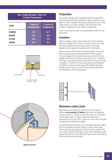
Existing Wall<br />
Plasterboard<br />
Insulation tucked<br />
into GTEC I Stud<br />
Movement Control Joint<br />
Movement control joints<br />
Movement control joints are required in wall linings at<br />
intervals not exceeding 10 metres and where the drylining<br />
crosses or abuts a structural movement joint. At movement<br />
control joints leave a 12.5mm opening between the<br />
plasterboards and use GTEC I Studs on each side of the joint<br />
to support the plasterboard edges.<br />
Cut GTEC Movement Control Joint to length. Butt joint lengths<br />
end to end where necessary. Attach to board surface with<br />
13mm stainless steel staples at 150mm centres. Apply GTEC<br />
Joint Filler or GTEC Allset Extra in two coats, feathering out the<br />
edges of the second coat. After finish-ing, remove the masking<br />
strip from the centre of the joint.<br />
Internal Corners<br />
THE INSTALLATION HANDBOOK 2008<br />
15