CFA Method of Drilled Shaft Construction CFA Method of Drilled
CFA Method of Drilled Shaft Construction CFA Method of Drilled
CFA Method of Drilled Shaft Construction CFA Method of Drilled

Create successful ePaper yourself
Turn your PDF publications into a flip-book with our unique Google optimized e-Paper software.
<strong>CFA</strong> <strong>Method</strong> <strong>of</strong> <strong>Drilled</strong><br />
<strong>Shaft</strong> <strong>Construction</strong><br />
Continuous flight augering can reduce costs and<br />
accelerate project schedules.<br />
C<br />
FA is a method in which shafts<br />
are drilled using a continuous<br />
flight auger with concrete<br />
placement occurring by pumping<br />
through the auger’s hollow stem<br />
while it is extracted. There are numerous<br />
benefits to this approach, including<br />
immediate replacement, zero subsidence,<br />
lack <strong>of</strong> free water within the<br />
shaft, computer monitoring <strong>of</strong> depth<br />
and concrete placement, and no need<br />
for casing/slurry. This is the most common<br />
drilling method in the UK for<br />
small to medium diameter shafts and is<br />
being heavily used by D. J. Scheffler— a<br />
specialist in deep foundation drilling<br />
and earth shoring work in difficult environments—in<br />
both California and the<br />
Northwest.<br />
The <strong>CFA</strong> installation method is similar<br />
to auger cast piling systems (ACIP),<br />
with the exception that the finished<br />
product is much more like that <strong>of</strong> a conventional<br />
drilled shaft. This is for two<br />
reasons: First, high strength concrete<br />
containing coarse aggregate is used in<br />
lieu <strong>of</strong> the sand/cement grout mixes<br />
common to ACIP piles. Second, <strong>CFA</strong><br />
piles utilize full length, standard rebar<br />
cages instead <strong>of</strong> short top cages and center<br />
bars. These differences are significant,<br />
as they increase the load capacity<br />
<strong>of</strong> the piles, allow use in applications<br />
with high lateral loads or seismic design<br />
criteria, and do not require significant<br />
modification to standard drilled shaft<br />
designs or specifications. In addition to<br />
the use <strong>of</strong> high strength concrete and<br />
full length rebar cages, <strong>CFA</strong> piles also<br />
differ from ACIP piles in that the<br />
onboard computer in the drill rig’s cab<br />
continuously measures depth, rotation,<br />
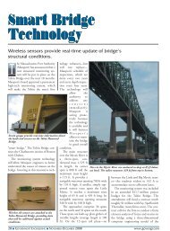
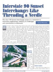
A steel element—either a cage or steel beam—is lowered into the fluid concrete by a<br />
support crane. Note the heavy plastic wheel centralizers designed to center the steel<br />
within the shaft.<br />
By Michael Zeman<br />
and concrete placement, as well as many<br />
other drill functions, to ensure that piles<br />
are constructed to the proper depth and<br />
that concrete is placed to the full diameter<br />
<strong>of</strong> the specified pile. The quality<br />
control <strong>of</strong> these piles is extremely high<br />
and can be monitored instantly not only<br />
by the drill operator, but also by the<br />
engineers through <strong>of</strong>fsite links to the<br />
computer in the drill rig.<br />
To better understand the <strong>CFA</strong><br />
method and how it can be implemented<br />
to reduce cost and schedule duration <strong>of</strong><br />
public projects, it is important to understand<br />
the method in which a <strong>CFA</strong> shaft<br />
is constructed, as well as how it differs<br />
from a conventional drilled shaft. At the<br />
beginning <strong>of</strong> a shift, the pumping lines<br />
connecting the concrete pump to the<br />
rig’s auger are primed and pre-charged<br />
with concrete. The drill rig is then positioned<br />
with its auger carefully centered<br />
over the pin marking the shaft center<br />
and the mast and auger are checked for<br />
verticality. Drilling commences and as<br />
the auger penetrates the ground, a small<br />
quantity <strong>of</strong> soil rises to the surface. The<br />
operator monitors the drilling process<br />
using the real-time information on the<br />
overhead screen; this information<br />
includes drill resistance, torque, depth,<br />
and penetration rate. The process continues<br />
until the preset tip elevation is<br />
met.<br />
Once the auger has reached the pile<br />
tip, concrete is immediately pumped<br />
through the auger. The auger is slowly<br />
raised as concrete continues to flow, with<br />
the operator monitoring the concrete<br />
pressure and oversupply to ensure complete<br />
replacement. During this part <strong>of</strong><br />
the process, the soil is removed continuously<br />
from the auger as it is extracted. A<br />
support excavator keeps the area around<br />
22 ■ GOVERNMENT ENGINEERING ■ JULY-AUGUST 2008 www.govengr.com
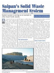
0 100<br />
0<br />
2<br />
4<br />
6<br />
8<br />
10<br />
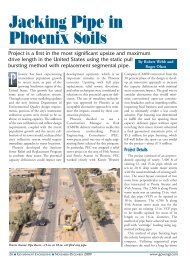
Length 10.04 m Revs<br />
610 mm diam <strong>CFA</strong><br />
24in foundation<br />
Penetration per rev<br />
(mm/rev)<br />
Depth (m)<br />
Auger Revs<br />
Concrete Vol (m3)<br />
MIRABELLA, Contract Number: 0800<br />
Torque<br />
(kN.m)<br />
Energy<br />
7.04 MJ<br />
(MJm³)<br />
Drill Resistance<br />
0 20 40 0 2 4 0 5 10 0 20 0 1 2 3 -305 0 305<br />
the auger free <strong>of</strong> excavated material. This<br />
process continues until the auger is fully<br />
extracted from the shaft. The support<br />
excavator clears away the remaining<br />
spoils, and then the crew carefully hand<br />
excavates any spoils or contaminated<br />
concrete at the top <strong>of</strong> the shaft until a<br />
perfect circle <strong>of</strong> concrete is exposed to<br />
the full diameter <strong>of</strong> the pile. A support<br />
crane then lowers the steel element,<br />
whether it is a cage or steel beam, into<br />
the fluid concrete <strong>of</strong> the shaft. In deep<br />
shafts, or shafts drilled in dry granular<br />
material, it is <strong>of</strong>ten necessary to apply a<br />
small amount <strong>of</strong> vibration to the steel<br />
element to assist with the cage insertion.<br />
The intent <strong>of</strong> this is not to force the steel<br />
into the concrete, but rather to simply<br />
assist the flow <strong>of</strong> the concrete around the<br />
cage or beam. It should be noted that<br />
centralizers, either rebar skids or heavy<br />
plastic wheels, are used to centralize the<br />
steel within the shaft and to ensure proper<br />
steel coverage.<br />
99.5<br />
Vol :<br />
Excess :<br />
3.7 m<br />
26.12 % Operator :<br />
Extraction Rate<br />
(m/min)<br />
Rig<br />
Oversupply<br />
(%)<br />
R516<br />
Pressure<br />
(bars)<br />
6<br />
SOUTH WALL<br />
29/04/2008<br />
Flow Pr<strong>of</strong>ile<br />
0<br />
1<br />
2<br />
3<br />
4<br />
5<br />
6<br />
7<br />
8<br />
9<br />
10<br />
12:58 12:59 13:00 13:01 13:02 13:03 13:04 13:05 13:06 13:07 13:08 13:09<br />
104<br />
95<br />
86<br />
77<br />
68<br />
59<br />
50<br />
41<br />
32<br />
23<br />
14<br />
5<br />
12:58 12:59 13:00 13:01 13:02 13:03 13:04 13:05 13:06 13:07 13:08 13:09<br />
3<br />
2<br />
1<br />
0<br />
12:58 12:59 13:00 13:01 13:02 13:03 13:04 13:05 13:06 13:07 13:08 13:09<br />
time<br />
13:04<br />
Piling instrumentation and control system.<br />
STEVE<br />
(mm)<br />
While the final product is nearly<br />
identical to a conventionally drilled<br />
shaft, there are significant differences in<br />
the installation process, each <strong>of</strong> which is<br />
important to consider when evaluating<br />
this method for a given project. Most<br />
importantly, there is never an open hole<br />
when drilling with the <strong>CFA</strong> method.<br />
With conventional drilling techniques,<br />
the drill tool repeatedly enters and exits<br />
the shaft, each time slowly advancing<br />
towards design tip elevation. To prevent<br />
the shaft from caving during this<br />
process, slurry and/or casing is used to<br />
provide support for the sidewalls in s<strong>of</strong>t<br />
or wet conditions. However, with the<br />
<strong>CFA</strong> method, there is no open drill<br />
hole, as it is fully supported by the auger<br />
and spoils during drilling, and supported<br />
by the concrete as the auger is<br />
extracted. This eliminates the need for<br />
casing and slurry, both <strong>of</strong> which significantly<br />
add to the time and cost <strong>of</strong> shafts<br />
in s<strong>of</strong>t or wet conditions.<br />
Another significant difference is that<br />
there is no free water within a <strong>CFA</strong><br />
shaft. In a conventional drilled shaft in<br />
wet conditions, free water enters the<br />
shaft and drilling is performed under a<br />
water or slurry head. However with<br />
<strong>CFA</strong>, very little soil is removed from the<br />
shaft until concrete placement begins,<br />
only enough to displace the volume <strong>of</strong><br />
the auger flights. Concrete is placed<br />
immediately as the auger is withdrawn,<br />
preventing the accumulation <strong>of</strong> free<br />
water in the shaft. This eliminates the<br />
need for collection, storage, and disposal<br />
<strong>of</strong> contaminated drilling fluids,<br />
important concerns on many shaft projects.<br />
From an efficiency standpoint, the<br />
largest difference is that the shaft is constructed<br />
in a continuous operation. In<br />
<strong>CFA</strong> shafts, the auger is advanced to tip<br />
in a single pass, concrete is placed as the<br />
auger is extracted, and the rebar cage is<br />
immediately set into place. This differs<br />
greatly from a conventional shaft in s<strong>of</strong>t<br />
or wet ground, in which the process <strong>of</strong><br />
drilling a single shaft includes advancing<br />
casing, taking multiple passes with a<br />
drill tool, cleaning the shaft bottom,<br />
placing reinforcement, placing concrete<br />
via tremie, extracting casing, and pumping<br />
<strong>of</strong>f displaced fluids. The elimination<br />
<strong>of</strong> these extra steps <strong>of</strong>ten allows <strong>CFA</strong><br />
shafts to be completed three to five<br />
times as quickly as a conventional<br />
drilled shaft.<br />
One <strong>of</strong> the greatest advantages <strong>of</strong> the<br />
<strong>CFA</strong> method is improved safety for the<br />
drill crew and inspection team.<br />
“Every year, throughout the U. S.,<br />
there is a worker in our industry lost to<br />
a cave-in <strong>of</strong> a drilled shaft during construction<br />
<strong>of</strong> conventional drilled shafts<br />
in less than ideal soil conditions. <strong>CFA</strong><br />
methods significantly reduce these risks<br />
by immediately replacing soil with concrete<br />
during extraction <strong>of</strong> the auger,”<br />
Dale Scheffler, president, D. J. Scheffler<br />
(www.djscheffler.com) says. “This is a<br />
much safer method since there is never<br />
an empty shaft.”<br />
Design Considerations<br />
Typically, a <strong>CFA</strong> pile <strong>of</strong> equal depth<br />
and diameter will have equal or slightly<br />
better load capacity when compared to a<br />
conventional drilled shaft. On projects<br />
www.govengr.com GOVERNMENT ENGINEERING ■ JULY-AUGUST 2008 ■ 23
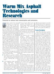
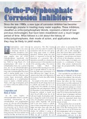
Among the reasons <strong>CFA</strong> was used at<br />
Pacific City was the developer was<br />
concerned about the use <strong>of</strong> the driven pile<br />
foundation system due to noise and<br />
vibrations so close to existing homes and<br />
the adjacent hotel.<br />
that have already been designed for<br />
drilled shafts, there is no need to switch<br />
engineering methodology in order to<br />
benefit from the use <strong>of</strong> the <strong>CFA</strong> methods.<br />
Even in cases where redesign is<br />
required, the design effort is <strong>of</strong>ten more<br />
than <strong>of</strong>fset by the cost and time savings<br />
during actual construction.<br />
Despite the advantages <strong>of</strong> the <strong>CFA</strong><br />
method, there are some things that need<br />
to be considered before specifying or<br />
utilizing this method on a particular<br />
project. First, the method does not allow<br />
for efficient drilling though hard<br />
bedrock conditions or large boulders.<br />
Second, there is an effective limit in how<br />
deep full length steel elements can be<br />
wet set into a <strong>CFA</strong> shaft. While<br />
advanced mix designs do allow cage<br />
installation as deep as 80 ft, shafts<br />
beyond this depth are typically best suited<br />
for conventional methods. Third, the<br />
diameter <strong>of</strong> the shaft needs to be considered.<br />
<strong>CFA</strong> is commonly used on<br />
drilled shafts up to 48 in. in diameter,<br />
and occasionally up to 60 in. in diameter.<br />
Beyond that, concrete supply limitations<br />
typically reduce the efficiency <strong>of</strong><br />
the method. For this reason, large diameter<br />
shafts are <strong>of</strong>ten best constructed<br />
using conventional methods.<br />
Case Studies<br />
The Scheffler companies have successfully<br />
completed numerous projects<br />
using the <strong>CFA</strong> method, and are preparing<br />
to start construction on several others<br />
within the next 12 months. The following<br />
are just a few examples, but they<br />
provide a range <strong>of</strong> applications under<br />
which <strong>CFA</strong> is an ideal method to construct<br />
drilled shafts.<br />
PCH Emergency Stabilization,<br />
Malibu, CA, Caltrans, 2005. Heavy<br />
run<strong>of</strong>f compromised a 50-year old<br />
drainage pipe located 45 ft below grade,<br />
creating a depression in the Pacific Coast<br />
Highway. D. J. Scheffler was selected to<br />
construct a secant pile wall with tiebacks<br />
along the centerline <strong>of</strong> the historic roadway.<br />
A series <strong>of</strong> overlapping 30-in. diameter<br />
piles were drilled to depths <strong>of</strong> up to<br />
65 ft using the <strong>CFA</strong> method, creating a<br />
continuous wall without the need for<br />
wood lagging. In five working days, 61<br />
total piles were installed, less than onethird<br />
the time it would have taken with<br />
conventional methods. In addition, the<br />
company installed 32 tiebacks, each with<br />
an average length <strong>of</strong> 60 ft. Given the critical<br />
nature <strong>of</strong> this roadway and the potential<br />
impacts to motorists, the time in<br />
which this wall was constructed provided<br />
an invaluable benefit to Caltrans and the<br />
local community as a whole.<br />
Pacific City Development,<br />
Huntington Beach, CA, Makar<br />
Development, 2007. Pacific City is a<br />
large mixed use development located<br />
directly across from the famous<br />
Huntington Beach. The original foundation<br />
design for the multiple structures<br />
was based upon the use <strong>of</strong> precast concrete<br />
piles driven into the dense sands<br />
located at a depth <strong>of</strong> about 40 ft from<br />
ground surface. However, before construction<br />
<strong>of</strong> the residential portion <strong>of</strong><br />
the site, the developer became concerned<br />
about the use <strong>of</strong> the driven pile<br />
foundation system due to noise and<br />
vibration levels in close proximity to<br />
existing homes and the adjacent hotel.<br />
Scheffler evaluated the load requirements<br />
<strong>of</strong> the original foundation system,<br />
as well as the geotechnical conditions<br />
<strong>of</strong> the site and determined that<br />
while a conventional drilled shaft foundation<br />
would be cost and schedule prohibitive,<br />
piles drilled using the <strong>CFA</strong><br />
method could easily achieve the<br />
required capacity at a lower cost than<br />
the original driven foundation system.<br />
After a series <strong>of</strong> pile tests, it was determined<br />
not only that the <strong>CFA</strong> piles<br />
exceeded the capacity <strong>of</strong> the driven piles<br />
by a factor ratio <strong>of</strong> 2:1 (30-in. diameter,<br />
55-in. depth), but that they also signifi-<br />
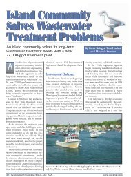
As opposed to auger cast piling systems, <strong>CFA</strong> delivers a finished product that is much<br />
more like that <strong>of</strong> a conventional drilled shaft.<br />
24 ■ GOVERNMENT ENGINEERING ■ JULY-AUGUST 2008 www.govengr.com
At Pacific City the use <strong>of</strong> <strong>CFA</strong> easily achieved the required capacity at less cost than the<br />
original driven foundation system.<br />
cantly exceeded the calculated capacity<br />
<strong>of</strong> conventional drilled shafts. Thirty-in.<br />
diameter piles were tested in compression<br />
to 1500 kips, with no sign <strong>of</strong> rapidly<br />
increasing settlement or other failure<br />
characteristics, remarkable considering<br />
the poor quality, saturated soils present<br />
in the upper 40 ft <strong>of</strong> the site.<br />
Installation <strong>of</strong> roughly 800 piles, ranging<br />
in depth from 40 to 55 ft, began this<br />
spring.<br />
BNSF Rail Expansion, Vancouver,<br />
WA, 2008. This project includes the<br />
construction <strong>of</strong> a 200-ft long secant pile<br />
wall with 48-in. diameter primary and<br />
secondary piles placed on 60-in. centers.<br />
The ground conditions generally consist<br />
<strong>of</strong> loose sandy silts over dense saturated<br />
gravels. The primary secant piles contain<br />
full length reinforcement cages with<br />
up to 24 #11 bars and #5 spiral with<br />
five-in. pitch. The reinforced piles range<br />
from 35 ft to 80.5 ft in depth.<br />
<strong>Construction</strong> began in May 2008 and<br />
the use <strong>of</strong> <strong>CFA</strong> is expected to reduce the<br />
construction schedule by roughly 40<br />
working days.<br />
GE<br />
Mr. Zeman is president <strong>of</strong> Scheffler<br />
Northwest, a partner company <strong>of</strong> D. J.<br />
Scheffler, Inc. located in Vancouver, WA. He<br />
can be reached at 360-818-0070 or<br />
mzeman@schefflernw.com.<br />
www.govengr.com GOVERNMENT ENGINEERING ■ JULY-AUGUST 2008 ■ 25