Ultromat AF/ATF Klemmenkasten, 1, en_GB - ProMinent
Ultromat AF/ATF Klemmenkasten, 1, en_GB - ProMinent
Ultromat AF/ATF Klemmenkasten, 1, en_GB - ProMinent

Create successful ePaper yourself
Turn your PDF publications into a flip-book with our unique Google optimized e-Paper software.
Operating Manual<br />
<strong>Ultromat</strong> ® <strong>AF</strong> and <strong>ATF</strong><br />
Continuous Flow System with<br />
Terminal Box<br />
Please carefully read these operating instructions before use! · Do not discard!<br />
The operator shall be liable for any damage caused by installation or operating errors!<br />
Technical changes reserved.<br />
Part No. 986397<br />
BA UL 016 04/09 <strong>GB</strong>
ProMin<strong>en</strong>t Dosiertechnik GmbH<br />
Im Schuhmachergewann 5-11<br />
69123 Heidelberg<br />
Telephone: +49 6221 842-0<br />
Fax: +49 6221 842-419<br />
email: info@promin<strong>en</strong>t.com<br />
Internet: www.promin<strong>en</strong>t.com<br />
986397, 1, <strong>en</strong>_<strong>GB</strong><br />
© 2009<br />
2
Table of cont<strong>en</strong>ts<br />
Table of cont<strong>en</strong>ts<br />
1 <strong>Ultromat</strong> ® Product Id<strong>en</strong>tification............................................ 5<br />
1.1 <strong>Ultromat</strong> ® <strong>AF</strong> Product Id<strong>en</strong>tification.............................. 5<br />
1.2 <strong>Ultromat</strong> ® <strong>ATF</strong> Product Id<strong>en</strong>tification............................ 5<br />
1.3 <strong>Ultromat</strong> ® <strong>AF</strong>/<strong>ATF</strong> Front View....................................... 5<br />
1.4 <strong>Ultromat</strong> ® <strong>AF</strong>/<strong>ATF</strong> Plan View........................................ 6<br />
1.5 About This Product....................................................... 6<br />
2 Safety Chapter...................................................................... 7<br />
2.1 Explanation of the Safety Information........................... 7<br />
2.2 Correct and Proper Use................................................ 8<br />
2.3 Users' Qualifications..................................................... 9<br />
2.4 Information in the Ev<strong>en</strong>t of an Emerg<strong>en</strong>cy.................. 10<br />
2.5 Description and Testing of the Safety Equipm<strong>en</strong>t....... 10<br />
2.6 <strong>Ultromat</strong> ® Safety Information...................................... 11<br />
2.7 Sound Pressure Level................................................ 11<br />
3 Transport and Storage of the System................................. 12<br />
3.1 Transport and Storage of the System......................... 12<br />
4 Information on the System.................................................. 13<br />
4.1 Application.................................................................. 13<br />
4.2 Design......................................................................... 13<br />
4.3 System Sizes.............................................................. 13<br />
5 Design and Function .......................................................... 16<br />
5.1 Three-Chamber Reservoir.......................................... 16<br />
5.2 Flush Fitting................................................................ 16<br />
5.3 Dry Material Feeder (<strong>ATF</strong> only).................................. 16<br />
5.4 Agitators...................................................................... 17<br />
5.5 Power Socket for the Connection of a Conveyor ....... 17<br />
5.6 Terminal Box............................................................... 17<br />
5.7 Crane Lifting Lugs....................................................... 17<br />
5.8 <strong>Ultromat</strong> ® Options....................................................... 17<br />
5.8.1 Agitator for Chamber 3 (Agitator 3).......................... 17<br />
5.8.2 Overflow Protection for the <strong>Ultromat</strong> ® ..................... 17<br />
5.8.3 Vibrator ................................................................... 17<br />
6 Assembly and Installation................................................... 18<br />
6.1 Assembly.................................................................... 18<br />
6.2 Installation - Hydraulic................................................ 18<br />
6.3 Installation - Electrical................................................. 19<br />
7 Control ............................................................................... 20<br />
7.1 Terminal Boxes <strong>AF</strong>/<strong>ATF</strong>............................................. 20<br />
8 Commissioning................................................................... 21<br />
8.1 Assembly, Preparatory Work...................................... 21<br />
8.2 Settings for Commissioning........................................ 21<br />
8.3 Water Supply Setting.................................................. 21<br />
8.4 Calibrating the Dry Material Feeder............................ 22<br />
8.5 Adjusting the Conc<strong>en</strong>tration........................................ 22<br />
8.5.1 Adjusting the Conc<strong>en</strong>tration of the Polymer Solution in<br />
the <strong>Ultromat</strong> ® <strong>AF</strong> / <strong>ATF</strong>............................................ 22<br />
8.6 Adjusting the Capacitive S<strong>en</strong>sor................................. 23<br />
8.7 Operation of the System............................................. 23<br />
3
Table of cont<strong>en</strong>ts<br />
9 Operation of the System..................................................... 25<br />
9.1 Prerequisites for Correct and Proper Operation......... 25<br />
9.2 Feeding the Dry Material Feeder with Powdered Polymer<br />
(<strong>ATF</strong>)........................................................................... 25<br />
9.3 Behaviour Wh<strong>en</strong> Switching on Mains Power and in the<br />
Ev<strong>en</strong>t of Mains Power Failure..................................... 25<br />
9.4 Decommissioning....................................................... 25<br />
9.5 Disposal...................................................................... 26<br />
10 Incorrect Operation of the System...................................... 27<br />
11 Troubleshooting.................................................................. 28<br />
11.1 Unspecified Malfunctions.......................................... 28<br />
11.2 S<strong>en</strong>sors..................................................................... 28<br />
12 Maint<strong>en</strong>ance....................................................................... 29<br />
12.1 Dry Material Feeder.................................................. 29<br />
12.2 Cleaning the Scre<strong>en</strong> Insert in the Pressure<br />
Reducer.................................................................... 29<br />
12.3 Dismantling the Cover of an Inspection Op<strong>en</strong>ing..... 29<br />
12.4 Cleaning the Surface of the <strong>Ultromat</strong> ® ...................... 29<br />
13 Spare Parts and Accessories.............................................. 30<br />
14 App<strong>en</strong>dix............................................................................. 31<br />
15 Declaration of Conformity................................................... 33<br />
16 Index................................................................................... 34<br />
4
<strong>Ultromat</strong>® Product Id<strong>en</strong>tification<br />
1 <strong>Ultromat</strong> ® Product Id<strong>en</strong>tification<br />
1.1 <strong>Ultromat</strong> ® <strong>AF</strong> Product Id<strong>en</strong>tification<br />
<strong>Ultromat</strong> <strong>AF</strong> 1035607 1035610 1035612 1035644 1035646 1035648<br />
Type <strong>AF</strong> 400 <strong>AF</strong> 1000 <strong>AF</strong> 2000 <strong>AF</strong> 4000 <strong>AF</strong> 6000 <strong>AF</strong> 8000<br />
Reservoir<br />
cont<strong>en</strong>t (litre)<br />
400 1000 2000 4000 6000 8000<br />
1.2 <strong>Ultromat</strong> ® <strong>ATF</strong> Product Id<strong>en</strong>tification<br />
<strong>Ultromat</strong> <strong>ATF</strong> 1035608 1035611 1035613 1035645 1035647 1035649<br />
Type <strong>ATF</strong> 400 <strong>ATF</strong> 1000 <strong>ATF</strong> 2000 <strong>ATF</strong> 4000 <strong>ATF</strong> 6000 <strong>ATF</strong> 8000<br />
Reservoir<br />
cont<strong>en</strong>t (litre)<br />
400 1000 2000 4000 6000 8000<br />
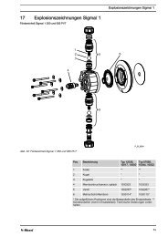
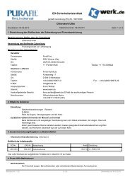
1.3 <strong>Ultromat</strong> ® <strong>AF</strong>/<strong>ATF</strong> Front View<br />
Fig. 1: <strong>Ultromat</strong> <strong>AF</strong>/<strong>ATF</strong> front view<br />
1. Agitator for chamber 1 8. Overflow<br />
2. Dry material feeder (<strong>ATF</strong>) 9. Shut-off valve<br />
3. Liquid polymer connection 10. Flow meter<br />
A - 5
<strong>Ultromat</strong>® Product Id<strong>en</strong>tification<br />
4. Y-Flush inlet 11. Sol<strong>en</strong>oid valve<br />
5. Agitator for chamber 2 12. Pressure reducer<br />
6. Terminal box 13. Shut-off fitting<br />
7. Agitator for chamber 3 (optional)<br />
1.4 <strong>Ultromat</strong> ® <strong>AF</strong>/<strong>ATF</strong> Plan View<br />
Fig. 2: <strong>Ultromat</strong> <strong>AF</strong>/<strong>ATF</strong> plan view<br />
1. Dry material feeder (<strong>ATF</strong>) 6. Discharge pipework<br />
2. Motor for dry material feeder (<strong>ATF</strong>) 7. Inspection op<strong>en</strong>ing for chamber 2<br />
3. Inspection op<strong>en</strong>ing for chamber 3 8. Metering pipe heating (<strong>ATF</strong>)<br />
4. Filling level gauge s<strong>en</strong>sor for chamber 3 9. Inspection op<strong>en</strong>ing for chamber 1<br />
5. Shut-off valves<br />
1.5 About This Product<br />
The <strong>Ultromat</strong> ® <strong>AF</strong>/<strong>ATF</strong> from ProMin<strong>en</strong>t is a preparation system for<br />
polyelectrolytes for connection to an external control.<br />
The <strong>Ultromat</strong> ® <strong>AF</strong> can be used in any application where synthetic<br />
liquid polymers have to be prepared for working solutions.<br />
The <strong>Ultromat</strong> ® <strong>ATF</strong> can be used in any application where free-flowing<br />
synthetic powder polymers or liquid polymers have to be prepared<br />
for working solutions.<br />
A - 6
Safety Chapter<br />
2 Safety Chapter<br />
<strong>Ultromat</strong> ® <strong>AF</strong>/<strong>ATF</strong><br />
2.1 Explanation of the Safety Information<br />
Introduction<br />
These operating instructions provide information on the technical<br />
data and functions of the product. These operating instructions<br />
provide detailed safety information and are provided as clear stepby-step<br />
instructions.<br />
The safety information and notes are categorised according to the<br />
following scheme. A number of differ<strong>en</strong>t symbols are used to d<strong>en</strong>ote<br />
differ<strong>en</strong>t situations. The symbols shown here serve only as examples.<br />
DANGER!<br />
Nature and source of the danger<br />
Consequ<strong>en</strong>ce: Fatal or very serious injuries.<br />
Measure to be tak<strong>en</strong> to avoid this danger.<br />
Danger!<br />
– D<strong>en</strong>otes an immediate threat<strong>en</strong>ing danger. If this is<br />
disregarded, it will result in fatal or very serious injuries.<br />
WARNING!<br />
Nature and source of the danger<br />
Possible consequ<strong>en</strong>ce: Fatal or very serious injuries.<br />
Measure to be tak<strong>en</strong> to avoid this danger.<br />
Warning!<br />
– D<strong>en</strong>otes a possibly hazardous situation. If this is<br />
disregarded, it could result in fatal or very serious<br />
injuries.<br />
CAUTION!<br />
Nature and source of the danger<br />
Possible consequ<strong>en</strong>ce: Slight or minor injuries. Material<br />
damage.<br />
Measure to be tak<strong>en</strong> to avoid this danger.<br />
Caution!<br />
– D<strong>en</strong>otes a possibly hazardous situation. If this is<br />
disregarded, it could result in slight or minor injuries.<br />
May also be used as a warning about material<br />
damage.<br />
A1 - 7
Safety Chapter<br />
NOTICE!<br />
Nature and source of the danger<br />
Damage to the product or its surroundings.<br />
Measure to be tak<strong>en</strong> to avoid this danger.<br />
Note!<br />
– D<strong>en</strong>otes a possibly damaging situation. If this is<br />
disregarded, the product or an object in its vicinity<br />
could be damaged.<br />
Type of information<br />
Hints on use and additional information.<br />
Source of the information. Additional measures.<br />
Information!<br />
– D<strong>en</strong>otes hints on use and other useful information.<br />
It does not indicate a hazardous or damaging situation.<br />
2.2 Correct and Proper Use<br />
WARNING!<br />
Danger caused by incorrect use!<br />
Incorrect use of the <strong>Ultromat</strong> ® can result in hazardous<br />
situations.<br />
– The <strong>Ultromat</strong> ® is only designed to produce a polymer<br />
solution as a floccul<strong>en</strong>t from powdered polymer or<br />
liquid conc<strong>en</strong>trate and with drinking water.<br />
– All other uses or a modification of the system are<br />
only permitted with the writt<strong>en</strong> authorisation of ProMin<strong>en</strong>t<br />
Dosiertechnik GmbH, Heidelberg!<br />
– The system is not designed for use in areas at risk<br />
from explosion!<br />
– The correct and proper operation of the system<br />
cannot be guaranteed if non-g<strong>en</strong>uine parts or third<br />
party accessories are used.<br />
– Please observe the relevant national regulations<br />
and the information provided in the operating<br />
instructions at all phases of the system's life!<br />
– The <strong>Ultromat</strong> ® may only be operated by adequately<br />
qualified personnel<br />
A1 - 8
Safety Chapter<br />
2.3 Users' Qualifications<br />
WARNING!<br />
Danger of injury with inadequately qualified personnel!<br />
If inadequately qualified personnel work on the unit or<br />
loiter in the hazard zone of the unit, this could result in<br />
dangers that could cause serious injuries and material<br />
damage.<br />
– All work on the unit should therefore only be<br />
conducted by qualified personnel.<br />
– Unqualified personnel should be kept away from the<br />
hazard zone.<br />
Activity<br />
Assembly / Installation<br />
Commissioning<br />
Operation<br />
Maint<strong>en</strong>ance / Repair<br />
Decommissioning / Disposal<br />
Troubleshooting<br />
Training<br />
trained qualified personnel<br />
technical experts<br />
instructed personnel<br />
Customer service departm<strong>en</strong>t<br />
technical experts<br />
instructed personnel<br />
Explanation of the terms:<br />
• A technical expert is deemed to be a person who is able to assess<br />
the tasks assigned to him and recognise possible hazards based<br />
on his/her technical training and experi<strong>en</strong>ce, as well as knowledge<br />
of pertin<strong>en</strong>t regulations.<br />
Note: A technical qualification is typically prov<strong>en</strong> by the required<br />
completion of a technical training course. The assessm<strong>en</strong>t of a<br />
person's technical training can also be based on several years<br />
of work in the relevant field.<br />
• A qualified employee is deemed to be a person who is able to<br />
assess the tasks assigned to him and recognise possible<br />
hazards based on his/her technical training, knowledge and<br />
experi<strong>en</strong>ce, as well as knowledge of pertin<strong>en</strong>t regulations.<br />
Note: The assessm<strong>en</strong>t of a person's technical training can also<br />
be based on several years of work in the relevant field.<br />
• An instructed person is deemed to be a person who has be<strong>en</strong><br />
instructed and, if required, trained in the tasks assigned to him/<br />
her and possible dangers that could result from improper behaviour,<br />
as well as having be<strong>en</strong> instructed in the required protective<br />
equipm<strong>en</strong>t and protective measures.<br />
• Customer service departm<strong>en</strong>t refers to service technicians, who<br />
have received prov<strong>en</strong> training and have be<strong>en</strong> authorised by<br />
ProMin<strong>en</strong>t to work on the system.<br />
Note for the system operator<br />
The pertin<strong>en</strong>t accid<strong>en</strong>t prev<strong>en</strong>tion regulations, as well as<br />
all other g<strong>en</strong>erally acknowledged safety regulations,<br />
must be adhered to!<br />
A1 - 9
Safety Chapter<br />
2.4 Information in the Ev<strong>en</strong>t of an Emerg<strong>en</strong>cy<br />
WARNING!<br />
Information in the Ev<strong>en</strong>t of an Emerg<strong>en</strong>cy<br />
Possible consequ<strong>en</strong>ce: Fatal or very serious injuries.<br />
Switch off the system with the red-yellow mains switch.<br />
External control and control cabinet!<br />
The red-yellow mains switch is located on the operator's<br />
side. Its precise location dep<strong>en</strong>ds on the layout on<br />
site. The operator is responsible for labelling this<br />
switch.<br />
2.5 Description and Testing of the Safety Equipm<strong>en</strong>t<br />
CAUTION!<br />
Propellers are rotating in the reservoirs!<br />
Slight or minor injuries.<br />
Switch off the system and only th<strong>en</strong> remove the screwed<br />
cover of an inspection op<strong>en</strong>ing!<br />
Fig. 3: Safety equipm<strong>en</strong>t<br />
Warning labels<br />
• 1 Warning label "Warning of injury to hands"<br />
• 2 Warning label "Warning of hazardous electrical voltage"<br />
• 3 Warning label "Warning of hot surfaces" (<strong>ATF</strong>)<br />
Test: Check whether the labels are still affixed and legible.<br />
A1 - 10
Safety Chapter<br />
2.6 <strong>Ultromat</strong> ® Safety Information<br />
WARNING!<br />
Qualification of personnel<br />
Danger due to incorrect operation of the system<br />
The operating personnel must be instructed by a ProMin<strong>en</strong>t<br />
service technician" (Wh<strong>en</strong> the system is first operated)<br />
The operating instructions must be available by the<br />
system!<br />
WARNING!<br />
Danger of electric shock!<br />
Possible consequ<strong>en</strong>ce: Fatal or very serious injuries<br />
The control cabinet must always be closed during operation.<br />
The mains switch must be set to "0" and secured against<br />
restart before any installation or maint<strong>en</strong>ance work can<br />
begin.<br />
CAUTION!<br />
Propellers are rotating in the reservoirs!<br />
Slight or minor injuries.<br />
Switch off the system and only th<strong>en</strong> remove the screwed<br />
cover of an inspection op<strong>en</strong>ing!<br />
CAUTION!<br />
A screw conveyor and a loos<strong>en</strong>ing wheel are located<br />
under the safety guard of the dry material feeder.<br />
Slight or minor injuries. Material damage.<br />
Do not reach into the dry material feeder.<br />
CAUTION!<br />
Hot surface!<br />
Incorrectly set heating on the metering pipe may<br />
become hot!<br />
Ensure that the metering pipe heating is correctly set!<br />
2.7 Sound Pressure Level<br />
The sound pressure level is < 70 dB (A) for powdered polymer,<br />
according to EN ISO 11202:1997 (Acoustics - Noise emission from<br />
machinery and equipm<strong>en</strong>t)<br />
A1 - 11
Transport and Storage of the System<br />
3 Transport and Storage of the System<br />
3.1 Transport and Storage of the System<br />
CAUTION!<br />
Fractures in plastic material may result from incorrect<br />
loading<br />
– Only move the <strong>Ultromat</strong> ® system wh<strong>en</strong> empty<br />
– The reservoir wall may not be subjected to point<br />
loads<br />
– Avoid heavy vibrations and impact loads<br />
– Only move the system with suitable hoisting and<br />
lifting equipm<strong>en</strong>t<br />
– Wh<strong>en</strong> using forklift trucks, use long forks, which<br />
ext<strong>en</strong>d across the <strong>en</strong>tire depth of the three-chamber<br />
reservoir<br />
– If a crane is used, fit the transport belts such that<br />
shear stress is avoided, ev<strong>en</strong> if lifting lugs exist<br />
– The support must be able to carry the weight of the<br />
system<br />
Ambi<strong>en</strong>t conditions for storage and transport<br />
Permissible ambi<strong>en</strong>t temperature: -5 °C to +50 °C<br />
Humidity: none<br />
Other: No dust, no direct sunlight<br />
A2 - 12
Information on the System<br />
4 Information on the System<br />
4.1 Application<br />
The <strong>Ultromat</strong> ® <strong>AF</strong>/<strong>ATF</strong> manufactured by ProMin<strong>en</strong>t is a polyelectrolyte<br />
preparation system.<br />
4.2 Design<br />
Almost all commercially available polymers can be used.<br />
Conc<strong>en</strong>trations of 0.05 to 0.5 % can be set. The viscosity of the<br />
polymer solution produced may not exceed 1500 mPas. Please refer<br />
to the application data sheets of the polymer suppliers for information<br />
about the viscosity of the differ<strong>en</strong>t polymer solutions.<br />
Adjust the flow rate of the preparation water to make full use of the<br />
preparation chamber. Conc<strong>en</strong>trations of greater than 0.5 % can<br />
reduce the capacity of the preparation performance.<br />
The maturing time available for the production of a polymer solution<br />
dep<strong>en</strong>ds on the discharge quantity and the volumetric capacity of the<br />
<strong>Ultromat</strong> ® and is approximately 60 minutes at a maximum discharge<br />
rate.<br />
4.3 System Sizes<br />
System sizes<br />
Please refer to the dim<strong>en</strong>sions sheet for the precise<br />
dim<strong>en</strong>sions of the individual <strong>Ultromat</strong> ® system!<br />
<strong>Ultromat</strong> <strong>AF</strong> 400 1000 2000 4000 6000 8000<br />
Reservoir<br />
cont<strong>en</strong>t (litre)<br />
Chamber<br />
volume (l)<br />
Discharge<br />
rate (l/h)<br />
Maturing time<br />
(min)<br />
Dim<strong>en</strong>sions<br />
LxWxH (mm)<br />
Net weight<br />
(kg)<br />
Total weight<br />
(kg)<br />
Overflow<br />
connection<br />
400 1000 2000 4000 6000 8000<br />
133 333 666 1333 2000 2666<br />
400 1000 2000 4000 6000 8000<br />
60 60 60 60 60 60<br />
1770x915x88<br />
6<br />
2420x960x12<br />
36<br />
3100x1150x1<br />
385<br />
3181x1478x1<br />
923<br />
4034x1682x1<br />
923<br />
140 350 400 550 850 1150<br />
540 1350 2400 4550 6850 8850<br />
DN 40 DN 50 DN 50 DN 65 DN 65 DN 80<br />
4589x1922x2<br />
290<br />
A3 - 13
Information on the System<br />
<strong>Ultromat</strong> <strong>AF</strong> 400 1000 2000 4000 6000 8000<br />
Discharge<br />
connection<br />
Water supply<br />
for redilution<br />
Liquid<br />
conc<strong>en</strong>trate<br />
pipework<br />
Max. water<br />
supply<br />
Elec. power<br />
input<br />
DN 25 DN 25 DN 32 DN 40 DN 40 DN 50<br />
1" 1" 1" 1 1/2" 11/2" 2"<br />
DN 15 DN 15 DN 15 DN 20 DN 20 DN 20<br />
1500 l/h 1500 l/h 3,000 l/h 6,000 l/h 8,000 l/h 12,000 l/h<br />
1.5 kW 2.6 kW 3.2 kW 5.0 kW 5.0 kW 9.5 kW<br />
External fuse 25 A 25 A 25 A 25 A 25 A 40 A<br />
Agitator 1<br />
Output 0.25 kW 0.55 kW 0.75 kW 1.10 kW 1.10 kW 2.20 kW<br />
Speed (50<br />
Hz)<br />
Protection<br />
class<br />
750 rpm 750 rpm 750 rpm 750 rpm 750 rpm 750 rpm<br />
IP 55 IP 55 IP 55 IP 55 IP 55 IP 55<br />
Agitator for<br />
chambers 2 +<br />
3 (optional)<br />
Output 0.18 kW 0.55 kW 0.75 kW 1.10 kW 1.10 kW 1.10 kW<br />
Speed (50<br />
Hz)<br />
Protection<br />
class<br />
750 rpm 750 rpm 750 rpm 750 rpm 750 rpm 750 rpm<br />
IP 55 IP 55 IP 55 IP 55 IP 55 IP 55<br />
<strong>Ultromat</strong> <strong>ATF</strong> 400 1000 2000 4000 6000 8000<br />
Reservoir<br />
cont<strong>en</strong>t (litre)<br />
Chamber<br />
volume (l)<br />
Discharge<br />
rate (l/h)<br />
Maturing time<br />
(min)<br />
Dim<strong>en</strong>sions<br />
LxWxH (mm)<br />
Net weight<br />
(kg)<br />
Total weight<br />
(kg)<br />
Overflow<br />
connection<br />
Discharge<br />
connection<br />
400 1000 2000 4000 6000 8000<br />
133 333 666 1333 2000 2666<br />
400 1000 2000 4000 6000 8000<br />
60 60 60 60 60 60<br />
1770x915x88<br />
6<br />
2420x960x12<br />
36<br />
3100x1150x1<br />
385<br />
3181x1478x1<br />
923<br />
4034x1682x1<br />
923<br />
180 390 440 590 890 1190<br />
580 1390 2440 4590 6890 9190<br />
DN 40 DN 50 DN 50 DN 65 DN 65 DN 80<br />
DN 25 DN 25 DN 32 DN 40 DN 40 DN 50<br />
4589x1922x2<br />
290<br />
A3 - 14
Information on the System<br />
<strong>Ultromat</strong> <strong>ATF</strong> 400 1000 2000 4000 6000 8000<br />
Water supply<br />
for redilution<br />
Liquid<br />
conc<strong>en</strong>trate<br />
pipework<br />
Max. water<br />
supply<br />
Elec. power<br />
input<br />
1" 1" 1" 1 1/2" 11/2" 2"<br />
DN 15 DN 15 DN 15 DN 20 DN 20 DN 20<br />
1500 l/h 1500 l/h 3,000 l/h 6,000 l/h 8,000 l/h 12,000 l/h<br />
1.5 kW 2.6 kW 3.2 kW 5.0 kW 5.0 kW 9.5 kW<br />
External fuse 25 A 25 A 25 A 25 A 25 A 40 A<br />
Agitator 1<br />
Output 0.25 kW 0.55 kW 0.75 kW 1.10 kW 1.10 kW 2.20 kW<br />
Speed (50<br />
Hz)<br />
Protection<br />
class<br />
750 rpm 750 rpm 750 rpm 750 rpm 750 rpm 750 rpm<br />
IP 55 IP 55 IP 55 IP 55 IP 55 IP 55<br />
Agitator for<br />
chambers 2 +<br />
3 (optional)<br />
Output 0.18 kW 0.55 kW 0.75 kW 1.10 kW 1.10 kW 1.10 kW<br />
Speed (50<br />
Hz)<br />
Protection<br />
class<br />
750 rpm 750 rpm 750 rpm 750 rpm 750 rpm 750 rpm<br />
IP 55 IP 55 IP 55 IP 55 IP 55 IP 55<br />
Powder<br />
feeder<br />
Type TGD 18.13 TGD 18.13 TGD 18.13 TGD 30.13 TGD 30.13 TGD 38.13<br />
Maximum<br />
metering<br />
output at 50<br />
Hz<br />
9 kg/h 9 kg/h 9 kg/h 28 kg/h 28 kg/h 55 kg/h<br />
A3 - 15
Design and Function<br />
5 Design and Function<br />
Description of the compon<strong>en</strong>t groups<br />
5.1 Three-Chamber Reservoir<br />
The PP reservoir is divided into three separate chambers, so that a<br />
suffici<strong>en</strong>t maturing time for the polymer solution can be <strong>en</strong>sured. The<br />
division of the reservoir largely prev<strong>en</strong>ts the matured and freshly<br />
prepared solution from mixing and <strong>en</strong>sures continuous discharge.<br />
The fill level of reservoir 3 is monitored by a fill level gauge. The<br />
system is provided with a minimum and maximum contact to start or<br />
stop the preparation process as well as an empty contact to prev<strong>en</strong>t<br />
it from running dry and a further s<strong>en</strong>sor that provides overflow protection<br />
Water pipework<br />
The water pipework supplies the system with the required preparation<br />
water. The pressure reduced with strainer <strong>en</strong>sures that the<br />
correct operating pressure is limited and maintained. A sol<strong>en</strong>oid<br />
valve op<strong>en</strong>s and closes the water inlet. A manual shut-off valve also<br />
shuts off the supply of water for maint<strong>en</strong>ance work.<br />
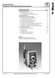
5.2 Flush Fitting<br />
The flush fitting <strong>en</strong>sures that the polymer is int<strong>en</strong>sively wetted with<br />
preparation water.<br />
1 Shut-off valve<br />
2 Pressure reducer<br />
3 Sol<strong>en</strong>oid valve<br />
4 Flow meter float<br />
5 Y-flush inlet<br />
Fig. 4: Flush fitting<br />
5.3 Dry Material Feeder (<strong>ATF</strong> only)<br />
Please refer to the separate operating instructions <strong>en</strong>titled "Dry<br />
material feeder" in this docum<strong>en</strong>tation for detailed information about<br />
the design and function of the equipm<strong>en</strong>t. The heating for the<br />
metering pipe and the minimum fill level s<strong>en</strong>sor for the dry material<br />
hopper are supplied as standard.<br />
A loos<strong>en</strong>ing wheel is fitted directly about the feeder screw for the<br />
continuous discharge of the powdered polymer. A metering pipe<br />
heating unit also removes any p<strong>en</strong>etrated moisture and thus<br />
prev<strong>en</strong>ts any caking of the powdered polymer.<br />
A4 - 16
Design and Function<br />
5.4 Agitators<br />
The <strong>Ultromat</strong> ® is fitted with two electrical agitators as standard. A<br />
third agitator for chamber 3 can be supplied as an option. The electrical<br />
agitators <strong>en</strong>sure that the polymer solution is g<strong>en</strong>tly agitated.<br />
The electrical agitator 1 has two propellers. The agitators can start<br />
up sudd<strong>en</strong>ly as soon as they are supplied with mains power!<br />
5.5 Power Socket for the Connection of a Conveyor<br />
The <strong>Ultromat</strong> ® has a power socket for the connection of a<br />
conveyor. The power socket is attached to the side of the terminal<br />
box and is secured electrically by a circuit breaker.<br />
5.6 Terminal Box<br />
The <strong>Ultromat</strong> ® has a terminal box for connection to an external<br />
control. The control is provided by the operator.<br />
5.7 Crane Lifting Lugs<br />
A suitable hoisting can be attached to the four crane lifting lugs.<br />
5.8 <strong>Ultromat</strong> ® Options<br />
The following options are available for the <strong>Ultromat</strong> ® .<br />
5.8.1 Agitator for Chamber 3 (Agitator 3)<br />
The <strong>Ultromat</strong> ® is fitted with two electrical agitators as standard. A<br />
third agitator for chamber 3 can be supplied as an option.<br />
5.8.2 Overflow Protection for the <strong>Ultromat</strong> ®<br />
The overflow protection signals that the <strong>Ultromat</strong> ® is overflowing<br />
5.8.3 Vibrator<br />
The vibrator helps to prev<strong>en</strong>t bridging in the dry material feeder so<br />
that the powdered polymer matures better.<br />
A4 - 17
Assembly and Installation<br />
6 Assembly and Installation<br />
The system is fully pre-assembled ex works. The cabling betwe<strong>en</strong><br />
the terminal box and the electrical power units is fully installed.<br />
6.1 Assembly<br />
WARNING!<br />
High fill weight in the system<br />
Possible consequ<strong>en</strong>ce: Fatal or very serious injuries.<br />
Ensure that the position of the system can bear the<br />
weight of the system wh<strong>en</strong> full.<br />
Accessibility of the system<br />
The system must be easily accessible at all times for<br />
operation, maint<strong>en</strong>ance and filling.<br />
Ambi<strong>en</strong>t conditions:<br />
Permissible ambi<strong>en</strong>t temperature: 5 ℃ to 40 ℃<br />
The system may not be exposed to cond<strong>en</strong>sation or rain.<br />
The system may not be exposed to direct sunlight.<br />
6.2 Installation - Hydraulic<br />
CAUTION!<br />
Damage to the <strong>en</strong>vironm<strong>en</strong>t by the polymer solution is<br />
possible!<br />
Observe the safety data sheet for the polymer and statutory<br />
regulations for disposal wh<strong>en</strong> draining the<br />
discharge lines and the overflow line!<br />
NOTICE!<br />
Prerequisites<br />
– The preparation water must be of drinking water<br />
quality<br />
– It must be free of solids and susp<strong>en</strong>ded particles<br />
– Inlet water pressure: 3 bar - 5 bar<br />
– The preparation water, overflow and discharge lines<br />
must have the correct dim<strong>en</strong>sions<br />
The overflow and discharge lines must be laid on a gradi<strong>en</strong>t and be<br />
operable without counter-pressure!<br />
1. Connect the line for the preparation water to the water fitting.<br />
2. Connect the feed pump to the discharge line.<br />
3. Connect up the discharge lines and lead into a suitable drain.<br />
4. Connect the overflow line to the overflow union and lead into a<br />
suitable drain.<br />
A5 - 18
Assembly and Installation<br />
6.3 Installation - Electrical<br />
WARNING!<br />
Danger of electric shock!<br />
Possible consequ<strong>en</strong>ce: Fatal or very serious injuries<br />
– The electrical installation may only be performed by<br />
a qualified electrician<br />
– Always disconnect the system from the mains power<br />
supply and prev<strong>en</strong>t it from being re-connected<br />
before undertaking any installation work in the electrical<br />
connections<br />
– Ensure that the cross-section of the cable is<br />
adequate<br />
– Ensure that the terminals are assigned correctly<br />
wh<strong>en</strong> connecting the units<br />
CAUTION!<br />
Danger of malfunction!<br />
Material damage<br />
Ensure that the motors are rotating in the right direction<br />
... wh<strong>en</strong> connecting the agitators, powder feeder<br />
and motor pumps<br />
A5 - 19
Control<br />
7 Control<br />
The <strong>Ultromat</strong> ® <strong>AF</strong> and <strong>ATF</strong> systems do not have a control. The<br />
control is provided by the operator.<br />
7.1 Terminal Boxes <strong>AF</strong>/<strong>ATF</strong><br />
The following electrical equipm<strong>en</strong>t is connected to the terminals in<br />
the terminal box:<br />
Terminal box<br />
• Agitator 1, 400 V<br />
• Agitator 2, 400 V<br />
• Heating for dry material feeder, 230 VAC, 25 W (control via integral<br />
timer relay)<br />
• Sol<strong>en</strong>oid valve for process water, 24 VDC, 15 W<br />
• Conductive level electrode: Dry run, Minimum and Maximum<br />
levels<br />
• Maximum contact for process water (water flow gauge)<br />
3 level relays are fitted in the terminal box to analyse the conductive<br />
level electrode.<br />
A6 - 20
Commissioning<br />
8 Commissioning<br />
8.1 Assembly, Preparatory Work<br />
CAUTION!<br />
Initial commissioning<br />
Possible material damage<br />
– It is ess<strong>en</strong>tial that the mechanical and electrical<br />
connections are checked to <strong>en</strong>sure that they are<br />
correct prior to initial commissioning<br />
– Ensure that the voltage, frequ<strong>en</strong>cy and curr<strong>en</strong>t type<br />
applied in the terminal box matches the data on the<br />
specification label<br />
– Observe the handling and set-up information<br />
contained in the previous chapters wh<strong>en</strong> commissioning<br />
for the first time<br />
Assembly<br />
1. Preparation water, discharge and overflow lines must be fitted<br />
and checked for leakage and correct operation.<br />
2. Provide adequate resources in the aforem<strong>en</strong>tioned quality.<br />
8.2 Settings for Commissioning<br />
Setting parameter for feed pipe heating<br />
Wh<strong>en</strong> delivered the timer relay in the terminal box is set to the<br />
following default values:<br />
Parameter Default values Range<br />
Heating switch-on time 5 s 1 - 10 s<br />
Heating switch-off time 35 s 30 - 100 s<br />
The parameters can be adapted to the process during commissioning.<br />
8.3 Water Supply Setting<br />
The water supply should be set to the following values.<br />
Type<br />
<strong>Ultromat</strong> ® 400<br />
<strong>Ultromat</strong> ® 1000<br />
<strong>Ultromat</strong> ® 2000<br />
<strong>Ultromat</strong> ® 4000<br />
<strong>Ultromat</strong> ® 6000<br />
<strong>Ultromat</strong> ® 8000<br />
Water supply<br />
1500 l/h<br />
1500 l/h<br />
3,000 l/h<br />
6,000 l/h<br />
9,000 l/h<br />
12,000 l/h<br />
A7 - 21
Commissioning<br />
8.4 Calibrating the Dry Material Feeder<br />
Calibration<br />
Required material:<br />
• Weighing scales<br />
• PE bag (capacity min. 500 g)<br />
1. Loos<strong>en</strong> the screw couplings to dismantle the flush fitting.<br />
2. Hold the PE bag (capacity min. 500 g) under the metering pipe<br />
and fill for 1 minute.<br />
ð<br />
Weigh the volume of discharged powder. This is the<br />
volume of "Grammes per minute wh<strong>en</strong> the pot<strong>en</strong>tiometer<br />
is set at 100%".<br />
3. Refit the flush fitting once the powder feeder has be<strong>en</strong> calibrated.<br />
8.5 Adjusting the Conc<strong>en</strong>tration<br />
8.5.1 Adjusting the Conc<strong>en</strong>tration of the Polymer Solution in the <strong>Ultromat</strong> ® <strong>AF</strong> / <strong>ATF</strong><br />
The metering rate for the dry material feeder or the conc<strong>en</strong>trate pump<br />
can be calculated from the water supply setting and the conc<strong>en</strong>tration<br />
required. Example:<br />
Water supply Conc<strong>en</strong>tration Metering rate of dry material<br />
feeder / conc<strong>en</strong>trate pump<br />
<strong>AF</strong> / <strong>ATF</strong> 400, <strong>AF</strong> / <strong>ATF</strong> 1000<br />
1500 l/h 0,1 % 1.5 kg/h<br />
1500 l/h 0,2 % 3.0 kg/h<br />
1500 l/h 0,3 % 4.5 kg/h<br />
1500 l/h 0,4 % 6.0 kg/h<br />
1500 l/h 0,5 % 7.5 kg/h<br />
<strong>AF</strong> / <strong>ATF</strong> 2000<br />
3,000 l/h 0,1 % 3.0 kg/h<br />
3,000 l/h 0,2 % 6.0 kg/h<br />
3,000 l/h 0,3 % 9.0 kg/h<br />
3,000 l/h 0,4 % 12.0 kg/h<br />
3,000 l/h 0,5 % 15.0 kg/h<br />
<strong>AF</strong> / <strong>ATF</strong> 4000<br />
6,000 l/h 0,1 % 6.0 kg/h<br />
6,000 l/h 0,2 % 12.0 kg/h<br />
6,000 l/h 0,3 % 18.0 kg/h<br />
6,000 l/h 0,4 % 24.0 kg/h<br />
6,000 l/h 0,5 % 30.0 kg/h<br />
A7 - 22
Commissioning<br />
Water supply Conc<strong>en</strong>tration Metering rate of dry material<br />
feeder / conc<strong>en</strong>trate pump<br />
<strong>AF</strong> / <strong>ATF</strong> 6000<br />
9,000 l/h 0,1 % 9.0 kg/h<br />
9,000 l/h 0,2 % 18.0 kg/h<br />
9,000 l/h 0,3 % 27.0 kg/h<br />
9,000 l/h 0,4 % 36.0 kg/h<br />
9,000 l/h 0,5 % 45.0 kg/h<br />
<strong>AF</strong> / <strong>ATF</strong> 8000<br />
12,000 l/h 0,1 % 12.0 kg/h<br />
12,000 l/h 0,2 % 24.0 kg/h<br />
12,000 l/h 0,3 % 36.0 kg/h<br />
12,000 l/h 0,4 % 48.0 kg/h<br />
12,000 l/h 0,5 % 60.0 kg/h<br />
8.6 Adjusting the Capacitive S<strong>en</strong>sor<br />
With an empty dry material feeder<br />
The capacitive s<strong>en</strong>sor for reporting a shortage of powder in the dry<br />
material feeder must be checked and possibly adjusted.<br />
The s<strong>en</strong>sor has a yellow LED at its cable <strong>en</strong>d to indicate the switching<br />
state and also a sunk<strong>en</strong> adjustm<strong>en</strong>t screw to adjust its s<strong>en</strong>sitivity.<br />
The s<strong>en</strong>sor is checked and adjusted in 2 steps:<br />
1. The yellow LED on the s<strong>en</strong>sor is not illuminated - the setting is<br />
correct.<br />
2. The yellow LED on the s<strong>en</strong>sor is illuminated:<br />
ð<br />
Reduce the s<strong>en</strong>sitivity on the adjustm<strong>en</strong>t screw (turn anticlockwise)<br />
until the LED goes out.<br />
With a filled dry material feeder<br />
1. The yellow LED on the s<strong>en</strong>sor is not illuminated - the setting is<br />
correct.<br />
2. The yellow LED on the s<strong>en</strong>sor is not illuminated:<br />
ð<br />
Increase the s<strong>en</strong>sitivity on the adjustm<strong>en</strong>t screw (turn<br />
clockwise) until the LED is illuminated.<br />
8.7 Operation of the System<br />
CAUTION!<br />
Large volumes of water of polymer solution can escape<br />
from the system!<br />
– Ensure that the discharge values are closed before<br />
starting the preparation process!<br />
A7 - 23
Commissioning<br />
CAUTION!<br />
Monitor the operation of the system in the start-up<br />
phase!<br />
– Monitor in particular the correct switching operation<br />
of the level s<strong>en</strong>sor wh<strong>en</strong> they first reach their respective<br />
switching points!<br />
Prerequisites:<br />
1. Correct and proper assembly and installation of the system has<br />
be<strong>en</strong> checked.<br />
2. The discharge valves are closed.<br />
3. All the operating parameters have be<strong>en</strong> set.<br />
4. All of the necessary equipm<strong>en</strong>t has be<strong>en</strong> calibrated.<br />
5. Start up the system<br />
ð<br />
the system starts up and begins the automatic preparation<br />
process.<br />
A7 - 24
Operation of the System<br />
9 Operation of the System<br />
9.1 Prerequisites for Correct and Proper Operation<br />
NOTICE!<br />
Instructed personnel<br />
– The system may only be operated by instructed<br />
personnel!<br />
Prerequisites:<br />
. Correct setting of the operating parameters.<br />
9.2 Feeding the Dry Material Feeder with Powdered Polymer (<strong>ATF</strong>)<br />
CAUTION!<br />
Danger of slipping!<br />
Mixtures of polymer and water are slippery!<br />
– Ensure that you have a secure foothold wh<strong>en</strong> filling<br />
the dry material feeder<br />
– Immediately remove any spilled powdered polymer<br />
or leaked polymer solution<br />
If the dry material feeder is not automatically filled, the supply of<br />
powdered polymer has to be continuously checked and refilled in<br />
time. This can be done while the system is operational.<br />
9.3 Behaviour Wh<strong>en</strong> Switching on Mains Power and in the Ev<strong>en</strong>t of Mains Power<br />
Failure<br />
Behaviour wh<strong>en</strong> switching on mains power and in the ev<strong>en</strong>t of mains<br />
power failure is dep<strong>en</strong>d<strong>en</strong>t on the external control and is the responsibility<br />
of the operator.<br />
9.4 Decommissioning<br />
For more than two days<br />
1. Completely empty the dry material feeder and/or liquid conc<strong>en</strong>trate<br />
feed.<br />
2. Empty the reservoir through the connections on the individual<br />
chambers provided for this.<br />
3. Carefully flush the reservoirs with water.<br />
4. In addition, rinse the flushing fitting.<br />
5. Carefully flush the line betwe<strong>en</strong> the reservoir and the feed<br />
pump.<br />
A8 - 25
Operation of the System<br />
9.5 Disposal<br />
NOTICE!<br />
Regulations<br />
– Please observe the curr<strong>en</strong>tly applicable local regulations<br />
(specifically with regard to electronic waste)<br />
– Please also read the operating instructions for the<br />
other equipm<strong>en</strong>t (dry material feeder, pumps ...)<br />
For Germany: The cleaned used parts can be disposed of at municipal<br />
waste collection points.<br />
A8 - 26
Incorrect Operation of the System<br />
10 Incorrect Operation of the System<br />
• The incorrect position of the discharge valves can result in<br />
malfunction<br />
• The incorrect position of the shut-off valves in the water supply<br />
line can result in malfunction<br />
• Unauthorised persons must be prev<strong>en</strong>ted from <strong>en</strong>tering or<br />
changing operating parameters<br />
• The maximum viscosity of 1500 mPas may not be exceeded<br />
wh<strong>en</strong> setting the conc<strong>en</strong>tration on the external control<br />
• The system will malfunction if the polymer supply is not refilled<br />
A9 - 27
Troubleshooting<br />
11 Troubleshooting<br />
CAUTION!<br />
Danger of sudd<strong>en</strong> start-up!<br />
Possible consequ<strong>en</strong>ce: Slight or minor injuries<br />
– The agitators and propeller may start up sudd<strong>en</strong>ly<br />
11.1 Unspecified Malfunctions<br />
Should a problem occur, which is not included in this list or should a<br />
listed fault not be remedied by the suggested troubleshooting measures,<br />
please contact ProMin<strong>en</strong>t Customer Services without delay.<br />
11.2 S<strong>en</strong>sors<br />
It should first be considered with every fault analysis that a capacitive<br />
proximity s<strong>en</strong>sor may possibly be erroneously signalling a fault.<br />
A10 - 28
Maint<strong>en</strong>ance<br />
12 Maint<strong>en</strong>ance<br />
The following compon<strong>en</strong>ts have to be maintained regularly. The<br />
intervals should be based on operating conditions.<br />
12.1 Dry Material Feeder<br />
Inspect the dry material feeder<br />
• Check the dry material feeder regularly during operation to<br />
<strong>en</strong>sure that it is working correctly<br />
• Check whether the powdered polymer is being metered correctly<br />
12.2 Cleaning the Scre<strong>en</strong> Insert in the Pressure Reducer<br />
Clean the scre<strong>en</strong> insert at the latest wh<strong>en</strong> 2/3 of the throughput<br />
surface of the scre<strong>en</strong> insert is dirty.<br />
• Manually close the shut-off valve upstream of the pressure<br />
reducer<br />
• Please refer to the manufacturer's instructions for further steps<br />
12.3 Dismantling the Cover of an Inspection Op<strong>en</strong>ing<br />
CAUTION!<br />
Danger of sudd<strong>en</strong> start-up!<br />
Slight or minor injuries<br />
– The agitators and propeller may start up sudd<strong>en</strong>ly<br />
The system must only be operated in principle wh<strong>en</strong> the inspection<br />
op<strong>en</strong>ings are tightly screwed.<br />
The covers may only be removed temporarily.<br />
After the inspection work, replace all covers and screw closed!<br />
12.4 Cleaning the Surface of the <strong>Ultromat</strong> ®<br />
CAUTION!<br />
Material damage<br />
Do not use cleaning ag<strong>en</strong>ts containing solv<strong>en</strong>ts.<br />
Clean the surfaces of the <strong>Ultromat</strong> ® if needed, as a slippery film can<br />
form on them over time.<br />
A11 - 29
Spare Parts and Accessories<br />
13 Spare Parts and Accessories<br />
Source<br />
Spare parts and accessories can be purchased from our Customer<br />
Service departm<strong>en</strong>t.<br />
A12 - 30
App<strong>en</strong>dix<br />
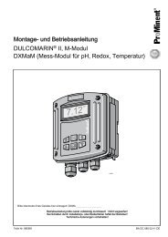
14 App<strong>en</strong>dix<br />
MSR diagram: <strong>Ultromat</strong> ® <strong>AF</strong>/<strong>ATF</strong> RI<br />
flow diagram<br />
<strong>Ultromat</strong> <strong>ATF</strong><br />
Wasser / water<br />
Flüssigkonz<strong>en</strong>trat/<br />
liquid polymer<br />
Trock<strong>en</strong>gut/powder<br />
M<br />
FI<br />
M M<br />
LSH<br />
LSL<br />
LSALL<br />
Fig. 5: <strong>Ultromat</strong> ® <strong>ATF</strong> RI flow diagram<br />
A13 - 31
App<strong>en</strong>dix<br />
<strong>Ultromat</strong> <strong>AF</strong><br />
FI<br />
Wasser / water<br />
Flüssigkonz<strong>en</strong>trat/<br />
liquid polymer<br />
M M<br />
LSH<br />
LSL<br />
LSALL<br />
Fig. 6: <strong>Ultromat</strong> ® <strong>AF</strong> RI flow diagram<br />
A13 - 32
Declaration of Conformity<br />
15 Declaration of Conformity<br />
Fig. 7: EU Declaration of Conformity<br />
A14 - 33
Index<br />
16 Index<br />
1, 2, 3 ...<br />
1500 mPas........................................................... 27<br />
A<br />
Accessibility.......................................................... 18<br />
Accessories.......................................................... 30<br />
Agitators............................................................... 17<br />
Application............................................................ 13<br />
Assembly.............................................................. 18<br />
C<br />
Calibration............................................................ 22<br />
Capacitive s<strong>en</strong>sor................................................. 23<br />
Commissioning..................................................... 21<br />
Crane Lifting Lugs................................................ 17<br />
D<br />
Decommissioning................................................. 26<br />
Disposal............................................................... 26<br />
Drinking water quality........................................... 18<br />
Dry material feeder............................................... 16<br />
F<br />
Feeder screw ...................................................... 17<br />
Feed pipe heating................................................ 21<br />
Flush fitting........................................................... 16<br />
I<br />
Incorrect operation............................................... 27<br />
Inspection op<strong>en</strong>ing............................................... 29<br />
Installation - Electrical.......................................... 19<br />
Installation - Hydraulic.......................................... 18<br />
L<br />
Loos<strong>en</strong>ing wheel.................................................. 17<br />
M<br />
mPas.................................................................... 13<br />
N<br />
Nominal discharge capacity................................. 13<br />
O<br />
Operation............................................................. 25<br />
Options................................................................. 17<br />
P<br />
Power socket........................................................ 17<br />
PP Reservoir........................................................ 16<br />
Propellers....................................................... 10, 28<br />
S<br />
Safety Information.................................................. 7<br />
Scre<strong>en</strong> insert........................................................ 29<br />
S<strong>en</strong>sor.................................................................. 23<br />
S<strong>en</strong>sors................................................................ 28<br />
Spare parts........................................................... 30<br />
Storage................................................................. 12<br />
Surfaces............................................................... 29<br />
System sizes........................................................ 13<br />
T<br />
Terminal box.................................................. 17, 20<br />
Three-Chamber Reservoir................................... 16<br />
Transport.............................................................. 12<br />
U<br />
<strong>Ultromat</strong>® <strong>AF</strong>/<strong>ATF</strong> front view................................. 6<br />
<strong>Ultromat</strong> Safety Information................................. 11<br />
Unspecified malfunctions..................................... 28<br />
Users' Qualifications.............................................. 9<br />
W<br />
Warning labels..................................................... 10<br />
Water supply........................................................ 21<br />
34