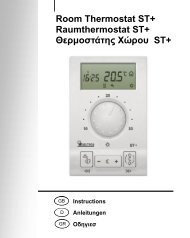
Instructions (PDF) - Seltron controllers
Instructions (PDF) - Seltron controllers
Instructions (PDF) - Seltron controllers

You also want an ePaper? Increase the reach of your titles
YUMPU automatically turns print PDFs into web optimized ePapers that Google loves.
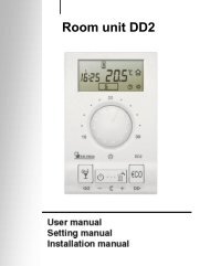
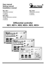
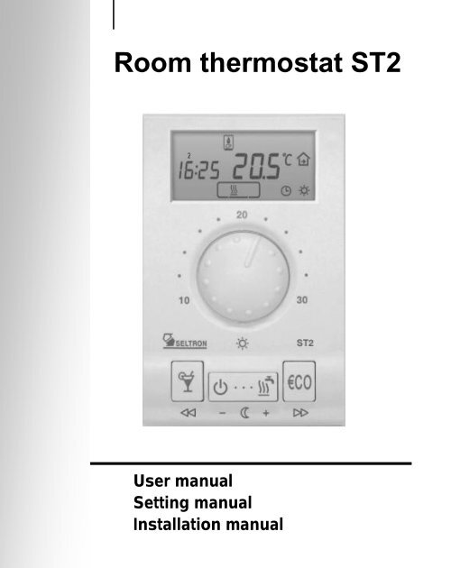
Room thermostat ST2<br />
User manual<br />
Setting manual<br />
Installation manual
Table of contents<br />
User manual<br />
Appearance and description .............................................................. 5<br />
Operating mode selection ................................................................. 7<br />
Setting the day and night temperature ............................................... 8<br />
Setting the comfort temperature ........................................................ 9<br />
PARTY and ECO mode ..................................................................... 9<br />
HOLIDAY mode .............................................................................. 10<br />
Setting the accurate time ................................................................. 11<br />
Program timer - programming ......................................................... 12<br />
Pre-setted time programs ................................................................ 14<br />
Anti-legionaries disease program .................................................... 16<br />
Manual domestic hot water warming activation ............................... 17<br />
Room thermostat locking ................................................................. 17<br />
Heating and cooling mode - selection.............................................. 18<br />
Remote control with telephone ........................................................ 18<br />
Auxiliary temperature sensor - temperature overview ...................... 18<br />
Command to quick save and quit (Escape) ..................................... 19<br />
Battery replacement ........................................................................ 19<br />
Setting manual<br />
Menu ............................................................................................... 20<br />
Radio connection - test mode for ST2TX ......................................... 28<br />
Factory settings - ST2 reset ............................................................ 29<br />
Controlled system - selection .......................................................... 30<br />
Installation manual<br />
Place of mount ................................................................................ 31<br />
Wall plate mount ............................................................................. 31<br />
Wiring connections .......................................................................... 33<br />
ST2R - ST2 with relay module R ..................................................... 34<br />
ST2R - direct heating circuit pump .................................................. 35<br />
ST2R - boiler control ....................................................................... 36<br />
ST2R - heating circuit with mixing valve (ON/OFF control) .............. 37<br />
ST2R - gas boiler ............................................................................ 38<br />
ST2R - electric floor heating ............................................................ 39<br />
ST2R - domestic hot water warming................................................ 40<br />
ST2RDR - ST2 with double relay module RDR .............................. 41
ST2RDR - direct heating circuit ...................................................... 42<br />
ST2RDR - direct heating circuit and domestic hot water ................. 43<br />
ST2RDR - indirect heating circuit (3 point control) .......................... 44<br />
ST2RDR - direct heating circuit and boiler with<br />
built in domestic hot water storage tank .......................................... 45<br />
ST2RDR - domestic hot water warming .......................................... 46<br />
ST2RDR - direct heating circuit and cooling .................................... 47<br />
ST2TX - ST2 with module for wireless control TX ........................... 48<br />
ST2JV - ST2 with module for gas boilers JV ................................... 48<br />
ST2JV - Junkers gas boilers ........................................................... 49<br />
ST2JV - Vaillant gas boilers ............................................................ 50<br />
ST2JVDR - ST2 with module for gas boilers JV and<br />
auxiliary relay module DR ............................................................... 51<br />
ST2JVDR - gas boiler Junkers and d. h. w. circulation .................... 52<br />
ST2JVDR - gas boiler Vaillant and d. h. w. circulation ..................... 53<br />
Connecting the Telewarm ............................................................... 54<br />
Connecting the auxiliary temperature sensor .................................. 54<br />
Error diagnostics ............................................................................. 55<br />
Technical data ................................................................................. 56<br />
Conformity with standards and directives ........................................ 57<br />
Guarantee ............................................................................................ 58<br />
Disposal of Old Electrical & Electronic Equipment ................................. 59<br />
Internet:<br />
www.seltron.info<br />
E- mail:<br />
info@seltron.info
Appearance and description<br />
ST2 is a powerful and efficient modular room thermostat with<br />
exchangeable modules. It can be used in heating or (and) cooling<br />
systems. It is suitable for radiator, convector and surface heating<br />
systems. This manual applies for:<br />
- ST2R - ST2 with relay module<br />
- ST2RDR - ST2 with double relay module<br />
- ST2JV - ST2 with module for Junkers and Vaillant gas boilers<br />
- ST2JVDR - ST2 with module for Junkers and Vaillant gas boilers<br />
and auxiliary relay module<br />
- ST2TX - ST2 with module for wireless control<br />
Room thermostat ST2 also enables connection of auxiliary temperature<br />
sensor 1 and remote activation with the telephone 1 .<br />
LEGEND<br />
Hold key while pressing other keys.<br />
Hold key until you hear a beep sound.<br />
Press and release key.<br />
Press key to increase or decrease value.<br />
1<br />
this option is not available in all ST2 editions<br />
USER MANUAL 5
Controlled devices<br />
- gas boiler<br />
- liquid fuel boiler<br />
- mixing valve<br />
- pump<br />
- d. h. w. storage tank<br />
Measured<br />
temperature<br />
Empty batteries<br />
Date and time<br />
Remote activation<br />
Frost protection<br />
Keyboard<br />
locking<br />
PARTY<br />
Knob for setting<br />
the day temperature<br />
Program timer CH2<br />
- d. h. w. warming<br />
ON - active<br />
OFF - inactive<br />
Program timer CH1<br />
- day. temperature<br />
<br />
- night temperature<br />
ECO<br />
Wireless mode<br />
Operation mode<br />
- off<br />
- heating<br />
- cooling<br />
- d. h. w. warming<br />
PARTY - day<br />
temperature mode<br />
Stand by<br />
mode<br />
Night<br />
temperature<br />
setting<br />
On mode -<br />
Operation<br />
according to the<br />
program timer<br />
ECO - saving<br />
temperature<br />
mode<br />
Picture 1<br />
6<br />
USER MANUAL
Operating mode selection<br />
Heating activation<br />
Press key to select the requested<br />
operating mode (Picture 2).<br />
Selected operation mode is indicated<br />
on display.<br />
- room heating<br />
- room cooling<br />
- domestic hot water warming<br />
Picture 2<br />
Room heating operates according to the program timer CH1, domestic hot water<br />
warming operates according to the program timer CH2.<br />
Stand-by<br />
Press key (Picture 3). On the<br />
display appears symbol .<br />
Frost protection remains active.<br />
Picture 3<br />
i changed in program group P1.3 (page 22).<br />
USER MANUAL<br />
7
Setting the day and night temperature<br />
Day temperature<br />
Turn knob to set the requested<br />
Picture 4<br />
Night temperature<br />
Hold key ( ) for approx. 5 seconds (Picture 5a). Release<br />
key after you hear a beep. Now press key ( ) or ( ) to set<br />
the requested night temperature (Picture 5b). To save and quit set<br />
-up, press key ( ) once again.<br />
Picture 5a<br />
Picture 5b<br />
8<br />
USER MANUAL
Setting the comfort temperature<br />
Hold key for 5 second (Picture 6a). Use key ( ) or ( ) to<br />
6b). To save and quit set-up, hold key<br />
for 5 seconds.<br />
Picture 6a<br />
Picture 6b<br />
Room heating with the comfort temp. operates according to the program timer CH3<br />
and has precedence over to room heating according to the program timer CH1.<br />
i<br />
If the comfort heating mode is inactive, the comfort temperature<br />
setting is also inactive. The comfort temperature<br />
mode is setted in program group P1.8 (page 22).<br />
PARTY and ECO operating mode<br />
PARTY - day temperature operation<br />
Press key . Use key ( ) or ( ) to set duration of the<br />
PARTY mode between 1 and 24 hours. For permanent PARTY<br />
mode, select on.<br />
To stop PARTY mode at anytime, press key .<br />
USER MANUAL<br />
9
ECO - night temperature operation<br />
Press key . Use key ( ) or ( ) to set duration of the<br />
ECO mode between 1 and 24 hours. For permanent ECO mode,<br />
select on.<br />
To stop ECO mode at anytime, press key .<br />
i<br />
The ECO temperature reduction is setted in<br />
program group P1.2 (page 22).<br />
Holiday mode<br />
Hold key for approximately 15 seconds. Release the key after<br />
you hear a beep. Use key ( ) or ( ) to set duration of the<br />
HOLIDAY mode between 1 and 99 days.<br />
To stop HOLIDAY mode at anytime, again hold the key for 15<br />
seconds.<br />
i<br />
The HOLIDAY mode temperature is setted in program<br />
group P1.4 (page 22). Factory pre-setted HOLIDAY<br />
.<br />
10<br />
USER MANUAL
Setting the accurate time<br />
Hours<br />
Hold key and press key ( )<br />
or ( ) to set the hours (Picture<br />
7).<br />
Minutes<br />
Hold key and press key<br />
( ) or ( ) to set the<br />
minutes (Picture 8).<br />
Picture 7<br />
Picture 8<br />
Day<br />
Hold both keys and , then<br />
press key ( ) or ( ) to set<br />
the day (Picture 9). The days are<br />
marked from 1 to 7. Monday is<br />
marked as 1 and Sunday as 7.<br />
i<br />
Picture 9<br />
while, the time is set to Monday, 20:00.<br />
USER MANUAL<br />
11
Program timer<br />
Program timer has three channels: CH1, CH2 and CH3.<br />
CH1 is used for programming the room heating (day / night),<br />
CH2 is used for programming the domestic hot water warming,<br />
CH3 is used for programming the comfort room heating.<br />
Selecting the program channel<br />
Hold key and press key (Picture 10). Release both keys<br />
after you hear a beep. Press key ( ) or key ( ) to select<br />
the program channel you wish to modify.<br />
Picture 10<br />
Modifying the time program<br />
Press key ( ) or ( ) to select the program place that you<br />
wish to modify. The display simultaneously writes out the time<br />
command, the successive number of the program space (Picture<br />
11) and switch-on/off command (picture 12, 13 and 14).<br />
Time<br />
command<br />
Successive number<br />
of the program space<br />
Picture 11<br />
12<br />
USER MANUAL
CH1<br />
Picture 12<br />
- day temperature<br />
- night temperature<br />
CH2<br />
Picture 13<br />
- active domestic hot<br />
water warming<br />
- inactive domestic hot<br />
water warming<br />
CH3<br />
Picture 14<br />
- active comfort temperature<br />
- inactive comfort temperature<br />
Now press key ( ). On the display starts to flash day. Press<br />
key ( ) or ( ) to set day, then press key ( ). On the<br />
display starts to flash hours. Press key ( ) or ( ) to set<br />
hours, then press key ( ). On the display starts to flash<br />
minutes. Press key ( ) or ( ) to set minutes, then press key<br />
( ). The display stops flashing. Now is possible to move to<br />
the next program space. Press ( ) to move to the next program<br />
space or press ( ) to move to the previous program space.<br />
Every channel in program timer (CH1, CH2 and CH3) has 32 program<br />
spaces. Time commands for day and night temperature<br />
mode, time commands for active and inactive d. h. w. warming and<br />
time commands for active and inactive comfort temp. mode are<br />
USER MANUAL<br />
13
successively followed.<br />
Unused time commands are indicated as - -:- - (picture 15). Room<br />
thermostat ST2 displays only used program spaces.<br />
Picture 15<br />
Unused time<br />
command<br />
Pre-setted time programs<br />
Room thermostat ST2 has 6 pre-setted time programs for room<br />
heating and 6 pre-setted time programs for domestic hot water<br />
warming. For each channel CH1 and CH2 is possible to select<br />
between 4 fixed (Pr1, Pr2, Pr3 and Pr4) and 2 users setted time<br />
programs (Pr1 and Pr2 ).<br />
Pre-setted time program selection<br />
Hold key and by pressing key select the suitable time<br />
program (Picture 16). Symbol indicates programs for room heating<br />
(CH1), symbol indicates programs for domestic hot water<br />
warming. (CH2). Te view the time commands in program, press key<br />
( ) or ( ).<br />
The selected time program always overwrites the previous one. To<br />
keep the current time program active, select - - -.<br />
14<br />
Picture 16<br />
USER MANUAL
- time program for<br />
room heating<br />
- time program for dom.<br />
hot water warming<br />
Day Time Day Time<br />
Day Time Day Time<br />
Day Time Day Time<br />
Day Time Day Time<br />
Table 1: Pre-setted time programs Pr1, Pr2, Pr3, Pr4<br />
USER MANUAL<br />
15
i<br />
In program timer CH1 and CH2 are factory<br />
pre-stored time programs Pr1.<br />
User pre-setted programs Pr1<br />
and Pr2<br />
Pre-setted time programs with a symbol , can be user modified.<br />
These programs can be changed or modified the same way as<br />
programs in program timer (see chapter Modifying the time program,<br />
on page 11).<br />
i<br />
By default is in program Pr1 , stored program Pr1 and<br />
for program Pr2 , program Pr3.<br />
Anti-legionaries disease program<br />
In order to protect against legionaries disease, this room unit has<br />
The function is activated with a five minute ON interval in the program<br />
timer (CH2).<br />
Example :<br />
D. h.w. ON D. h.w. OFF<br />
If no d. h .w. temperature sensor is connected the room thermostate<br />
will warm the d. h. w. for 2 hours.<br />
16<br />
USER MANUAL
i<br />
We suggest you, to run the anti-legionaries program once in<br />
a week during night time.<br />
Manual d. h. w. warming activation<br />
Hold key<br />
i<br />
for 5 seconds. Release the key after you hear a beep.<br />
Manual domestic hot warming is automatically deactivated,<br />
when requested d. h. w. temperature is reached or at the<br />
latest after 1 hour.<br />
Thermostat locking<br />
Hold key for 15 seconds. Release the key after you hear a<br />
beep. Symbol indicates locked room unit. To unlock the ST2,<br />
again hold key for 15 seconds.<br />
i<br />
ST2 locking is setted in service group S1.9 (page 24).<br />
USER MANUAL 17
Selection between heating or cooling<br />
To switchover between heating and cooling and in reverse, hold<br />
key for approximately 10 seconds (Picture 17). Release key<br />
after you hear a beep. The display writes out active mode for a<br />
few seconds, HEA - heating or COO - cooling (Picture 18).<br />
Picture 17 Picture 18<br />
Remote control<br />
With telephone is possible to remotely activate the day temperature<br />
mode. Remote activation is signalised with the symbol<br />
.This function is setted in Program group P3 (page 23).<br />
For analogue telephone line is available device G1-D. Device G44<br />
is intended for remote control with GSM mobile telephone.<br />
Auxiliary temperature sensor - temperature<br />
overview<br />
In normal display mode, hold key and press key (Escape).<br />
i .<br />
18 USER MANUAL
Command to quick save and quit (Escape)<br />
Every time you wish to quick store and quit set-up, hold key<br />
press key . Release both keys after you hear a beep.<br />
and<br />
i<br />
valid for program and service settings.<br />
Battery replacement<br />
Empty batteries are indicated with the<br />
symbol on display. We suggest the<br />
battery replacement every 2 years. ST2<br />
is supplied with two alkaline batteries 1.5<br />
V type AAA. Battery socket is inside the<br />
ST2. To remove thermostat from the wall<br />
plate, do the following. Hold thermostat<br />
in height of keys and pull it towards yourself<br />
(Picture 19 - OPEN). After battery<br />
exchange, put ST2 back on the wall<br />
plate, by doing the following. Hook ST2<br />
on top and push it with bottom towards<br />
the wall plate (Picture 19 - CLOSE).<br />
OPEN<br />
Picture 19<br />
CLOSE<br />
Battery exchange should be done within 20 seconds. In other case<br />
you will have to set the accurate time again.<br />
USER MANUAL 19
Menu<br />
All data and settings are joined into 16 groups:<br />
CH1 program timer for room heating<br />
CH2 program timer for d. h. w. warming<br />
CH3 program timer for comfort room heating<br />
d1<br />
room thermostat data<br />
P1 program group 1<br />
P2 program group 2<br />
P3 program group 3<br />
S1 service group 1<br />
S2 service group 2<br />
S3 service group 3<br />
Menu<br />
To enter menu, hold key and press key (Picture 26).<br />
Release keys after you hear a beep. The display writes out first<br />
group CH1.<br />
Picture 20<br />
20<br />
SETTING MANUAL
Menu navigation<br />
In menu, keys have new meaning, marked bellow them (Picture<br />
21). To move between the groups press key ( ) to move to the<br />
left and key ( ) to move to the right (Picture 22). To move<br />
within the group press key ( ) to move down between the lines<br />
and key ( ) to move up between the lines. For your better<br />
understanding all the lines are marked. First two symbols mark the<br />
group and the third symbol successive number of the line in group<br />
(Picture 23).<br />
Entrance<br />
Picture 21<br />
Move to<br />
the left<br />
Move down or<br />
decrease<br />
Move up or<br />
increase<br />
Move to<br />
the right<br />
Groups S are by default (factory) settings locked.<br />
Picture 22<br />
i<br />
Group locking is setted in Service group S3 (page 25).<br />
SETTING MANUAL<br />
21
Successive Nr.<br />
of the line<br />
Group<br />
name<br />
Parameter<br />
Picture 23<br />
Program timer for room heating CH1<br />
For changing the time program see chapter Modifying the time<br />
program (page 12).<br />
Program timer for domestic hot water warming CH2<br />
For changing the time program see chapter Modifying the time<br />
program (page 12).<br />
Program timer for comfort room heating CH3<br />
For changing the time program see chapter Modifying the time<br />
program (page 12).<br />
Room thermostat data d1<br />
This group is sort of ST2 ID. In this group are information about<br />
following order:<br />
- [d1.1] Room thermostat type (ST2)<br />
- [d1.2] Software version<br />
- [d1.3] Heating or cooling<br />
- [d1.4] ED constant or actuator speed or controlled device<br />
- [d1.5] Built-in temperature sensor calibration<br />
- [d1.6] Auxiliary temperature sensor calibration<br />
- [d1.7] Selected controlled system<br />
- [d1.8] Battery voltage<br />
- [d1.9] Reserved<br />
22<br />
SETTING MANUAL
Program group P1<br />
Program group P1 is used for the thermostat user settings. To<br />
change the selected parameter, hold key for approximately 5<br />
seconds. Parameter starts to flash. Press key ( ) or ( ) to<br />
set the parameter value. To store the setted value, again hold<br />
key for approximately 5 seconds.<br />
i<br />
This procedure, for modifying the parameter, is the same<br />
for all program and service groups.<br />
Group P1 contains the following parameters; (factory setting):<br />
- [P1.1]<br />
- [P1.2] - (-<br />
- [P1.3]<br />
- - - deactivated, P - temp. is setted with the knob);<br />
- [P1.4]<br />
- [P1.5] - - - deactivated); (20 min)<br />
- [P1.6] Display of controlled device (- - - none, 1 - oil boiler,<br />
2 - gas boiler, 3 - actuator, 4 - pump); (1)<br />
- [P1.7] Temperature sensor calibration (-<br />
- [P1.8] - - - inactive); (- - -)<br />
- [P1.9] Periodic activation of pumps and mixing valve<br />
(- - - deactivated, 1 - activated) 1 ; (1)<br />
1<br />
Activation is every Saturday at:<br />
21:01 - mixing valve or circulation pump activation<br />
21:02 - d. h. w. circulation pump activation<br />
SETTING MANUAL 23
Program group P2<br />
In program group P2 are the following parameters;<br />
(factory setting):<br />
- [P2.1]<br />
- [P2.2] Switch-on hysteresis for domestic hot water<br />
- [P2.3]<br />
- [P2.4] M<br />
- [P2.5] Naximal stand-<br />
- [P2.6]<br />
- [P2.7] Beeper mode (- - - silent, 1 - by typing, 2 - by program<br />
Timer changeover, 3 - by typing and program timer<br />
changeover); (1)<br />
- [P2.8] (1)<br />
- [P2.9] Radio module type (1 - AM module, 2 - FM module); (1)<br />
- [P2.10] Display of measured temperatures (1 - built in sensor,<br />
2 - auxiliary sensor, 3 - both sensors - alternating,<br />
4 - display of requested (setted) temperature,<br />
5 - return-pipe temperature sensor); (1)<br />
- [P2.11] (2 min)<br />
- [P2.12]<br />
Program group P3<br />
Program group P3 is intended to set the remote control with telephone.<br />
In program group P3 are the following parameters; (factory<br />
setting):<br />
- [P3.1] P - temperature<br />
setted with the knob); (P)<br />
24<br />
SETTING MANUAL
[P3.2] Operation mode (1 - room heating<br />
2 - domestic hot water warming, 3 - room heating and<br />
d. h. w. warming, 4 - changeover to cooling mode,<br />
5 - Party mode 1 ); (3)<br />
Service group S1<br />
program group S1 are the following parameters; (factory setting):<br />
- [S1.1] Controlled heating system<br />
(1 - heating circuit (ON / OFF control),<br />
2 - heating circuit (ON / OFF control) and dom. hot water,<br />
3 - heating circuit (3 point control),<br />
4 - heating circuit (ON / OFF control) + boiler with built in<br />
domestic hot water storage tank,<br />
5 - floor heating,<br />
6 - domestic hot water,<br />
7 - gas boiler Junkers or Vaillant (flame power modulation),<br />
8 - gas boiler Junkers or Vaillant and d. h. w. circulation),<br />
9 - heating circuit (ON / OFF control) and cooling;<br />
(depends on installed module - see Table 2)<br />
- [S1.2] Auxiliary sensor (- - - no sensor, 1 - room temp. sensor,<br />
2 - outdoor temp. sensor, 3 - d. h. w. temperature sensor,<br />
4 - floor temp. sensor, 5 - boiler temp. sensor,<br />
6 - stand-pipe temperature sensor)<br />
(depends on installed module - see Table 2)<br />
- [S1.3] Room temperature<br />
(1 - built-in sensor, 2 - auxiliary sensor,<br />
3 - min. measured temperature, 4 - max. measured temperature,<br />
5 - average temperature);<br />
- [S1.4] Auxiliary temperature sensor calibration<br />
(-<br />
- [S1.5] Measured temp. roundup<br />
SETTING MANUAL 1<br />
We recommend to use key.<br />
25
- [S1.6] Heating optimisation 1 (- - - deactivated, 1 - activated); (2)<br />
- [S1.7] Controlling algorithm<br />
(1 - P-controller, 2 - PI-controller); (P)<br />
- [S1.8] Pre-setted time programs - selection (- - - no selection,<br />
1 - fixed only, 2 - user programs only,<br />
3 - fixed and user progr.); (3)<br />
- [S1.9] Thermostat locking (- - - no locking, 1 - no locking, but<br />
limited function of key , 2 - enabled key Party and knob,<br />
3 - enabled only key Party, 4 - full lock); (2)<br />
- [S1.10] Relay output timeout - delay (- - - (- - -)<br />
1<br />
Heating optimisation: ST2 automatically calculates the switch-on<br />
time and at setted time (night-day changeover) the requested<br />
temperature is already reached.<br />
Service group S2<br />
settings. In program group S2 are the following parameters;<br />
(Factory setting):<br />
- [S2.1]<br />
- [S2.2]<br />
- [S2.3] Minimal temperature setting - limitation<br />
- - - no limitation); (- - -)<br />
- [S2.4] Maximal temperature setting - limitation<br />
- - - no limitation); (- - -)<br />
- [S2.5]<br />
- [S2.6] P-<br />
- [S2.7] Timer accuracy correction<br />
(- (0 sec/day)<br />
- [S2.8] 1<br />
; (1)<br />
- [S2.9] 1<br />
; (1)<br />
- [S2.10] 1<br />
; (1)<br />
26<br />
SETTING MANUAL
Service group S3<br />
program group S3 are the following parameters:<br />
- [S3.1] Group locking (- - - no locking,<br />
1 - locked are groups S,<br />
2 - locked are groups S and P,<br />
3 - locked complete menu); (1)<br />
i<br />
Access to parameter S3.1 is possible in the following way. Hold<br />
key for 20 seconds (picture 24). Release the key after you<br />
possible to modify this or any other parameter.<br />
1<br />
Parameters S2.8, S2.9 and S2.10 are intended only for heating<br />
circuit with 3 point control.<br />
Picture 24<br />
SETTING MANUAL 27
Radio connection - test mode for ST2TX<br />
Check if your receiver has the same radio channel number as setted<br />
in parameter S2.8 on ST2TX. Now activate test mode. Hold key<br />
and pres and hold key for 5 seconds (picture 25).<br />
Release the keys after you hear a beep.<br />
Picture 25<br />
Signal power indication by receivers RX2x, versions up to V1.9<br />
If the radio connection is established, R1 is activated and deactivated<br />
every 2 seconds. Receiver every 10 seconds lowers the reception<br />
intension, what is signalised with the light R2. Radio connection<br />
will operate without interceptions, if R1 is activated and<br />
deactivated also by lowered signal intensity.<br />
Signal power indication by receivers RX2x, version V2.0 or higher<br />
If the radio connection is established, R1 is activated and deactivated<br />
every 2 seconds. Signal light R2 indicates the signal intensity<br />
with flashing. Signal intensity is indicated with 1 to 5 flashes. Radio<br />
connection will operate without interruptions if the light R2 flashes<br />
at least 2 times.<br />
i<br />
Test mode automatically expires after 5 minutes. You can also end it by using the<br />
command ''Escape''.<br />
28<br />
SETTING MANUAL
Factory settings - ST2 reset<br />
To restore the factory settings<br />
hold keys and for approx.<br />
20 seconds (Picture 26). Release<br />
keys after you hear a beep.<br />
Picture 26<br />
SETTING MANUAL 29
Controlled heating system - selection<br />
S1.1 Controlled system ST2R ST2RDR ST2TX ST2JV ST2JVDR<br />
1<br />
Heating circuit<br />
(ON / OFF control)<br />
2<br />
Heating circuit<br />
(ON / OFF control)<br />
and d. h. w. warming<br />
3<br />
Heating circuit<br />
(3 point control)<br />
4<br />
Heating circuit and<br />
boiler<br />
(ON / OFF control)<br />
5 Floor heating<br />
6<br />
7<br />
8<br />
9<br />
LEGEND:<br />
Domestic hot water<br />
warming<br />
Gas boiler<br />
Junkers or Vaillant<br />
(flame power modulation)<br />
Gas boiler<br />
Junkers or Vaillant<br />
and d. h. w. circulation<br />
Heating circuit<br />
and cooling<br />
- factory setting - optional setting, where auxiliary<br />
- optional setting temperature sensor must be connected<br />
Table 2: Possible applications for particular modules<br />
i<br />
30<br />
For floor heating system an auxiliary temperature<br />
sensor must be connected.<br />
Thermostat automatically detects connected module and<br />
selects default controlled heating system for this module.<br />
INSTALLATION MANUAL
Place of mount<br />
Place of mount is very important for proper ST2 operation. Suitable<br />
sources of heat and wind. ST2 should be mounted approximately<br />
150 cm above the floor (Picture 27).<br />
Picture 27<br />
Wall plate mount<br />
Remove the ST2 from the<br />
wall plate, by doing the<br />
following. With one hand<br />
hold ST2 in height of keys<br />
and with other hand the wall<br />
plate. Now pull them apart<br />
(Picture 28).<br />
Picture 28<br />
SETTING MANUAL<br />
31
Unscrew and temporarily remove the protection cover (Picture 29).<br />
have installed a flush box, tear away the drilling template from the<br />
package and mark drilling holes. Use enclosed screws to fasten the<br />
wall plate on the wall (Picture 30). After you have done connecting<br />
the wires (see chapter Connecting the wires), screw back the<br />
protection cover. Now put ST2 back onto the base by doing the<br />
following. Hook ST2 on top of the wall plate and push it with bottom<br />
towards the wall plate (Picture 19- CLOSE).<br />
Picture 29 Picture 30<br />
Flush box<br />
Wall<br />
32 INSTALLATION MANUAL
Wires connection<br />
WARNING: Mounting and wiring connections must be done by a<br />
qualified installer or authorized company. Local regulations or VDE<br />
0100 and EN IEC 60364 regulations for electrical installations must<br />
be considered by doing the wiring connections.<br />
Bring the wires through the opening in bottom of the wall plate<br />
(Picture 30-position A). How to connect module is detailed<br />
described on pages 33 to 50.<br />
ST2 enables connection of following modules:<br />
- relay module (R)<br />
- auxiliary relay module (DR)<br />
- module for wireless control (TX)<br />
- module for Junkers and Vaillant gas boilers (JV)<br />
ST2 also enables connection of the:<br />
- auxiliary temperature sensor<br />
- device for remote control with telephone<br />
INSTALLATION MANUAL<br />
33
ST2R - ST2 with relay module R<br />
With room thermostat ST2 is possible to control:<br />
- direct heating circuit pump (picture 31)<br />
- boiler control (picture 32)<br />
- heating circuit with mixing valve (picture 33)<br />
- gas boiler (picture 34)<br />
- electric floor heating (picture 35)<br />
- domestic hot water warming (picture 36)<br />
Table bellow shows parameter S1.1 settings for thermostat ST2R.<br />
type description S1.1<br />
ST2R Direct heating circuit pump (picture 31) 1<br />
ST2R Boiler control (picture 32) 1<br />
ST2R<br />
Heating circuit with mixing valve<br />
(picture 33)<br />
1<br />
ST2R Gas boiler (picture 34) 1<br />
ST2R Electric floor heating (picture 35) 5<br />
ST2R Domestic hot water warming (picture 36) 6<br />
i<br />
ST2R default setting for parameter S1.1=1.<br />
34 INSTALLATION MANUAL
ST2R - direct heating circuit pump<br />
Parameter S1.1=1.<br />
Module R<br />
Picture 31<br />
INSTALLATION MANUAL 35
ST2R - boiler control<br />
Parameter S1.1=1.<br />
Module R<br />
Picture 32<br />
36<br />
INSTALLATION MANUAL
ST2R - heating circuit with mixing valve<br />
Parameter S1.1=1.<br />
Module R<br />
Picture 33<br />
INSTALLATION MANUAL<br />
37
ST2R - gas boiler<br />
Parameter S1.1=1.<br />
Module R<br />
Picture 34<br />
38<br />
INSTALLATION MANUAL
ST2R - electric floor heating<br />
Parameter S1.1=5.<br />
Module R<br />
Picture 35<br />
INSTALLATION MANUAL<br />
39
ST2R - domestic hot water warming<br />
Parameter S1.1=6.<br />
Module R<br />
Picture 36<br />
40<br />
INSTALLATION MANUAL
ST2RDR - ST2 with double relay module RDR<br />
With room thermostat ST2RDR is possible to control:<br />
- direct heating circuit<br />
- direct heating circuit and domestic hot water warming<br />
- indirect heating circuit - 3 point control<br />
- D. h. w. warming<br />
- direct heating circuit and boiler with built in domestic hot water<br />
storage tank (- direct heating circuit and cooling)<br />
type description S1.1<br />
ST2RDR Direct heating circuit (picture 37) 1<br />
ST2RDR<br />
ST2RDR<br />
ST2RDR<br />
Direct heating circuit and<br />
domestic hot water warming (picture 38)<br />
Indirect heating circuit<br />
- 3 point control (picture 39)<br />
Direct heating circuit and boiler with built in<br />
domestic hot water storage tank 1 (picture 40)<br />
2<br />
3<br />
4<br />
ST2RDR D. h. w. warming (picture 41) 6<br />
STRDR Direct heating circuit and cooling (picture 42) 9<br />
i<br />
ST2RDR default setting for parameter S1.1=2.<br />
1<br />
Boiler is activated when there is need for domestic hot water<br />
warming.<br />
INSTALLATION MANUAL<br />
41
ST2RDR - direct heating circuit<br />
Parameter S1.1=1.<br />
Module DR<br />
Module R<br />
Picture 37<br />
42<br />
INSTALLATION MANUAL
ST2RDR - direct heating circuit and domestic<br />
hot water warming<br />
Parameter S1.1=2.<br />
Module DR<br />
Module R<br />
Picture 38<br />
INSTALLATION MANUAL<br />
43
ST2RDR - indirect heating circuit (3 point<br />
control)<br />
Parameter S1.1=3.<br />
Modul DR<br />
Modul R<br />
Picture 39<br />
44<br />
INSTALLATION MANUAL
ST2RDR - direct heating circuit and boiler<br />
with built in d. h. w. storage tank<br />
Parameter S1.1=4.<br />
Picture 40<br />
Module DR<br />
Module R<br />
INSTALLATION MANUAL<br />
45
ST2RDR - d. h. w. warming<br />
Parameter S1.1=6.<br />
Module DR<br />
Module R<br />
Picture 41<br />
i<br />
The requested d. h. w. temperature is set between 20 and 80 °C<br />
with the knob on the thermostat.<br />
46 INSTALLATION MANUAL
ST2RDR - direct heating circuit and cooling<br />
Parameter S1.1=9.<br />
Module DR<br />
Module R<br />
Picture 42<br />
INSTALLATION MANUAL 47
ST2TX - ST2 with module for wireless<br />
control TX<br />
ST2TX enables wireless control for 9 different heating systems<br />
(see Table 2 on page 29). The receiver should be mounted in the<br />
near of controlled device.<br />
Thermostat and receiver must have the same radio channel Nr.<br />
(setting P2.8, page 23).<br />
Set the controlled heating system in service group S1.1 (page 24)<br />
(default factory setting is 1).<br />
For connecting the RX20 or RX22 see Receiver manual.<br />
ST2JV - ST2 with module for gas boilers JV<br />
With room thermostat ST2JV is possible to control:<br />
- flame power by Junkers gas boilers (picture 41)<br />
- flame power by Vaillant gas boilers (picture 42)<br />
Table bellow shows parameter S1.1 settings for thermostat ST2JV.<br />
type description S1.1<br />
ST2JV Gas boiler Junkers (picture 41) 7<br />
ST2JV Gas boiler Vaillant (picture 42) 7<br />
i<br />
48<br />
ST2JV default setting for parameter S1.1=7.<br />
INSTALLATION MANUAL
ST2JV - gas boiler Junkers<br />
Parameter S1.1=7.<br />
Module JV<br />
Picture 43<br />
INSTALLATION MANUAL<br />
49
ST2JV - gas boiler Vaillant<br />
Parameter S1.1=7.<br />
Module JV<br />
Picture 44<br />
50<br />
INSTALLATION MANUAL
ST2JVDR - ST2 with module for gas boilers<br />
JV and auxiliary relay module DR<br />
With ST2JVDR is possible to control:<br />
- flame power by Junker gas boilers and domestic hot water<br />
circulation (picture 43)<br />
- flame power by Vaillant gas boilers and domestic hot water<br />
circulation (picture 44)<br />
type description S1.1<br />
ST2JVDR<br />
ST2JVDR<br />
Gas boiler Junkers and domestic hot<br />
water circulation (picture 43)<br />
Gas boiler Vaillant and domestic hot<br />
water circulation (picture 44)<br />
8<br />
8<br />
Table: Parameter S1.1 value for ST2JVDR.<br />
i<br />
ST2JVDR default setting for parameter S1.1=8.<br />
INSTALLATION MANUAL<br />
51
ST2JVDR - Junkers gas boiler and domestic<br />
hot water circulation<br />
Parameter S1.1=8.<br />
Picture 45<br />
52<br />
Module DR<br />
Module JV<br />
INSTALLATION MANUAL
ST2JVDR - Vaillant gas boiler and domestic<br />
hot water circulation<br />
Parameter S1.1=8.<br />
Module DR<br />
Picture 46<br />
Module JV<br />
INSTALLATION MANUAL 53
Connecting the Telewarm<br />
Connect Telewarm G1-D or Telewarm G44 into the terminals a<br />
and b on the ST2 wall plate (picture 45). Before connecting into<br />
terminals a and b, remove the blank plastic bridge. To learn more<br />
about connecting the Telewarm on electric and telephone network<br />
see User manual for Telewarm.<br />
i<br />
If auxiliary relay module (DR), wireless module (TX) or<br />
auxiliary temperature sensor are installed, connection of<br />
Connecting the auxiliary temperature sensor<br />
Always connect the auxiliary temperature<br />
sensor into the connector<br />
terminals a and b on wall ST2 plate<br />
(Picture 45). Set the parameters for<br />
this sensor in service group S1.<br />
i<br />
Picture 45<br />
If auxiliary relay module (DR), remote control device or<br />
wireless module (TX) are installed, connection of auxiliary<br />
i<br />
54<br />
By room thermostat ST2RDR the additional sensor is connected<br />
in connectors 7 and 8.<br />
INSTALLATION MANUAL
On The DD2 can be connected only MURATA type sensors.<br />
This sensors are: outdoor sensor AF/M, room sensor PS10-<br />
12/M , immersion sensor TF/M.<br />
Error reports<br />
Sensor malfunction<br />
If auxiliary temp. sensor is in short circuit, the display writes out .<br />
If the auxiliary sensor is disconnected, the display writes out .<br />
TECHNICAL DATA, DECLARATIONS<br />
55
Technical data<br />
Model: ............................................ ST2<br />
Operation mode: ............................ P - regulator (ON / OFF),<br />
sliding mode or PI - controller<br />
(3 point control)<br />
Power supply: ................................. 2 batteries LR03, size AAA<br />
Relay output: .................................. 230 V ~ / 6 (3) A<br />
JV module: ..................................... 24 V output<br />
Radio module: ................................ 433.92 MHz, modulation OOK<br />
Consumption: ................................. I= 0,022 mA; P= 0,066 mW<br />
Temp. sensor type: ........................ Murata NTC<br />
Degree of protection: ...................... IP 30 by SIST EN 60529<br />
Safety class: ................................... II by SIST EN 60730-1<br />
Housing: ......................................... ABS thermoplast, white<br />
...................<br />
Weight: ........................................... 150 g<br />
56<br />
TECHNICAL DATA, DECLARATIONS
Conformity with standards and directives<br />
<strong>Seltron</strong> d.o.o. declares, with full responsibility, that room thermostat<br />
ST2 meet the requirements and rules for the electrical equipment,<br />
designed to use within certain voltage levels (EC directive<br />
for low voltage (LVD) 73/23 EEC, 93/68 EEC) and requirements<br />
and rules for electro-magnetic compatibility (EMC) (EC directive<br />
for electro-magnetic compatibility (EMC) 89/336 EEC, 92/31 EEC,<br />
93/68 EEC, 99/5/EEC).<br />
Product description: Room thermostat ST2<br />
Model: ST2R, ST2RDR, ST2TX, ST2JV, ST2JVDR<br />
Applied standards:<br />
SIST EN 60730-1:1995, SIST EN60730-2-9:1997,<br />
SIST EN 50081-1:1995, SIST EN 50082-1:1995,<br />
SIST EN 55014-1:2001, SIST EN 55014-2:1997,<br />
SIST EN 301 489-3: 2000, SIST EN 300 220-3:2000,<br />
SIST EN 60950:1992 (completion A:1993, A2:1993,<br />
A3:1995, A4:1997).<br />
TECHNICAL DATA, DECLARATIONS<br />
57
Guarantee<br />
This product complies with all the regulations and declared<br />
characteristics. We grant 2 years guarantee on the product,<br />
commencing on the date of purchase. We will eliminate any<br />
defects in the product resulting from faults in materials,<br />
workmanship, malfunctions or imperfection. We retain the right to<br />
repair or completely replace the product as we may choose.<br />
This guarantee does not cover damages as a result of improper<br />
use, normal wear and defects that have no effect on value,<br />
functionality and operation safety of the product. This guarantee<br />
becomes void if repairs are done by unauthorized person or<br />
original spare parts are not used.<br />
For service within the guarantee period, hand or send the<br />
complete product, together with the sales receipt to authorised<br />
service or dealer. This guarantee is valid in every country, where<br />
the product was supplied by company SELTRON or its authorised<br />
dealer.<br />
58<br />
GUARANTEE 58
Disposal of Old Electrical & Electronic<br />
Equipment<br />
Disposal of Old Electrical & Electronic Equipment (Applicable<br />
in the European Union and other European countries with separate<br />
collection systems)<br />
This symbol on the product or on its packaging indicates<br />
that this product shall not be treated as household<br />
waste. Instead it shall be handed over to the<br />
applicable collection point for the recycling of electrical<br />
and electronic equipment. By ensuring this product<br />
is disposed of correctly, you will help prevent<br />
potential negative consequences for the environment and human<br />
health, which could otherwise be caused by inappropriate waste<br />
handling of this product. The recycling of materials will help to<br />
conserve natural resources. For more detailed information about<br />
recycling of this product, please contact your local city office, your<br />
household waste disposal service or the shop where you purchased<br />
the product.<br />
REMOVAL OF THE PRODUCT 59
SELTRON d.o.o.<br />
Ru{ka cesta 96<br />
2345 Bistrica ob Dravi<br />
SI - SLOVENIJA<br />
Tel: +386 (0)2 671 96 00<br />
Fax: + 386 (0)2 671 96 66<br />
http://www.seltron.eu<br />
Email: info@seltron.eu<br />
J5060352<br />
V1.1<br />
V2.2