QUIC-LIFT⢠Ladder aCCess sysTem - Ziamatic Corp
QUIC-LIFT⢠Ladder aCCess sysTem - Ziamatic Corp
QUIC-LIFT⢠Ladder aCCess sysTem - Ziamatic Corp

Create successful ePaper yourself
Turn your PDF publications into a flip-book with our unique Google optimized e-Paper software.
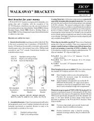
<strong>QUIC</strong>-LIFT <strong>Ladder</strong> Access System (LAS)<br />
Electric Locking System<br />
Field Installation Guide<br />
ZICO ®<br />
3097PM8<br />
REV. 1-25-13<br />
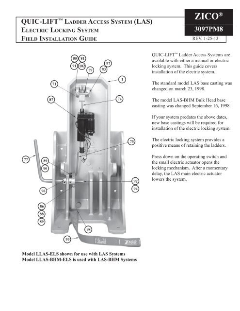
<strong>QUIC</strong>-LIFT <strong>Ladder</strong> Access Systems are<br />
available with either a manual or electric<br />
locking system. This guide covers<br />
installation of the electric system.<br />
The standard model LAS base casting was<br />
changed on march 23, 1998.<br />
The model LAS-BHM Bulk Head base<br />
casting was changed September 16, 1998.<br />
If your system predates the above dates,<br />
new base castings will be required for<br />
installation of the electric locking system.<br />
The electric locking system provides a<br />
positive means of retaining the ladders.<br />
Press down on the operating switch and<br />
the small electric actuator opens the<br />
locking mechanism. After a momentary<br />
delay, the LAS main electric actuator<br />
lowers the system.<br />
Model LLAS-ELS shown for use with LAS Systems<br />
Model LLAS-BHM-ELS is used with LAS-BHM Systems
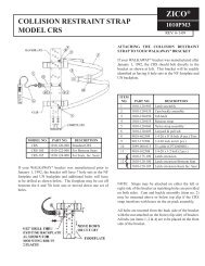
Use eye protection while working with spring (81)<br />
Use extreme care when loading and unloading spring on tool (102)<br />
Remove and discard tool after pin (83) is installed<br />
COMPONENT PARTS FOR MANUAL AND ELECTRIC<br />
LOCKING SYSTEMS - EXPLODED VIEW<br />
-2-
ITEM NO. PART NO. DESCRIPTION QTY.<br />
70<br />
3097-280-101 Base casting for LAS<br />
3097-107-101 Base casting for LAS-BHM<br />
}1<br />
71 3097-280-103 Latch casting 1<br />
72 3097-280-105 Hook casting 1<br />
73 3097-280-107 Latch keeper casting 1<br />
74 3097-285-109 Upper rod 1<br />
75 3097-285-111 Lower road 1<br />
77 3097-280-115 Handle 1<br />
78 3097-280-117 Crank arm 1<br />
79 3097-280-119 Link pin 1<br />
80 3097-280-121 Link plate 2<br />
81 3097-280-123 Latch spring 1<br />
82 3097-280-125 Keeper spring 1<br />
83 9080-004336 Clevis pin - 7/16 x 2-1/4 1<br />
84 9040-101214 Spring pin - 1/8 x 7/8 1<br />
85 9010-163712 Screw, hex head - 3/8-16 x 3/4 S/S 2<br />
86 9010-332522 Screw, allen - 1/4-20 x 1-3/8 1<br />
87 3097-285-135 Electric actuator 1<br />
88 9013-172500 Nut, self-locking - 1/4-20 4<br />
89 9014-112500 Washer, plain - 1/4 ID 4<br />
90 9070-000608 Cotter pin - 1/16 x 1/2 1<br />
91 9070-000912 Cotter pin - 3/32 x 3/4 2<br />
92 9010-103180 Screw - 5/16-18 x 5 1<br />
94 9013-103100 Nut - 5/16-18 2<br />
95 9014-203100 Washer, lock - 5/16 ID 1<br />
96 3097-280-127 Shaft collar - 1/2" 2<br />
97 9070-001216 Cotter pin - 1/8 x 1 1<br />
98 0000-000-120 Key ring - 1" 1<br />
99 3097-280-129 Strap - 1" W x 24" L 1<br />
100 9014-203700 Lockwasher, split - 3/8 ID 2<br />
101 3097-285-200 Control panel assembly (not shown) 1<br />
102 3097-280-131 Spring installation tool 1<br />
103 3097-725-113 Hook spacer 3<br />
Hook Casting and Latch<br />
Keeper Assembly attached to<br />
channel support 3097-105-154<br />
or 3097-105-155. Parts 72,<br />
73, 82, 84 85 & 100.<br />
-3-
Note: Numbers in parenthesis refer to item numbers (see LAS manual page 34).<br />
1. With ladders removed and system in stored position, install 5-1/16 x 2-3/4 Bolt (92) through LAS Base<br />
Casting, then lower system completely.<br />
2. Connect Handle (77) and Crank Arm (78) to LAS Base Casting using two 1/2" Shaft Collars (96), one Hex<br />
Head Screw (86), and one 1/4-20 Self-Locking Nut (88). See cover page for additional reference.<br />
-4-
3. Build Sub Assembly by combining Link Plate (80) with Link Pin (79) and Cotter Pin (91), then position<br />
Sub Assembly to Latch Casting (71).<br />
4. Remove shipping ziptie from the Latch Spring (81) and Spring Installation Tool (102).<br />
-5-
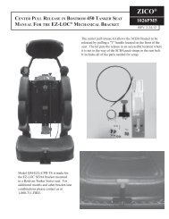
5. Place Spring Installation Tool (102) with mounted Latch Spring (81), shorter side of spring up, into the<br />
Latch Casting as shown. Install Latch Casting with Sub Assembly and Spring Installation Tool into LAS<br />
Base Casting using Clevis Pin (83) and Cotter Pin (97). Remove Spring Installation Tool from Latch<br />
Spring, leaving Latch Spring in place.<br />
-6-
Shown with Spring Installation Tool Removed<br />
-7-
6. Prepare Latch Actuators<br />
A. Install Upper Rod (74) into stationary end of Electric Actuator (87).<br />
B. Install Lower Rod (75) into ram end of Electric Actuator (87).<br />
-8-
7. Connect Upper Rod<br />
A. Insert threaded end of Upper Rod (74) up through the slot in the Latch Casting (71) and thread it into<br />
the Link Pin (79) until rod extends out 1/4".<br />
B. Hold Electric Actuator (87) square at base and add Nut (88) to threaded end of Upper Rod (74)<br />
through Sub Assembly and tighten.<br />
-9-
8. Connect Lower Rod<br />
A. Turn ram end of Electric Actuator (87) until ram is fully extended outward 1".<br />
B. Adjust position of Lower Rod (75) until it engages the hole in the Crank Arm (78).<br />
C. Secure Lower Rod (75) to Crank Arm (78) with Washer (89) and Cotter Pin (90).<br />
-10-
9. Push Handle and confirm that latch system is operating properly.<br />
Proper Locked Position<br />
Proper Unlocked Position<br />
10. Install the pre-assembled Hook (72) and Latch Keeper (73) castings to the LAS Channel Support with two<br />
Hex Head Bolts (85) and two Lock Washers (100), using the holes provided. Apply striker grease to Hook<br />
and Latch Keeper.<br />
Inside View<br />
Outside View<br />
-11-
11. Raise LAS system to full "UP" position until actuators ratchet. Looking through the side of the unit,<br />
confirm that the Latch Assembly is fully engaging the Hook and Latch Keeper. Lock is properly adjusted<br />
if Hook moves towards the Base Casting when lock is unlatched.<br />
Fully Engaged<br />
Not Fully Engaged<br />
12. If Hook is not fully engaging, you can add shims under the hook to adjust. Note: If more than one shim<br />
is needed, you'll need to use longer bolts with Hook and Latch Keeper Assembly.<br />
Shown with Shim<br />
13. Manually unlock LAS System and lower to full "DOWN" position.<br />
14. Wire and mount the <strong>Ladder</strong> Control Circuit and Control Panel (101). See pages 14 & 15.<br />
15. Read and understand the Mode of Operaiton, then complete a test run.<br />
-12-
ITEM NO. PART NO. DESCRIPTION QTY.<br />
1 3097-285-113 Nameplate (not shown) 1<br />
2 3097-285-115 Mounting Plate 1<br />
3 3097-285-117 Switch, 3P2T MOM 1<br />
3B 3097-105-145 Boot, Toggle Switch 1<br />
4 3097-285-119 Relay 1<br />
5 3097-285-121 Timer 1<br />
6 3097-285-123 Resister 1<br />
7 3097-285-125 Fuseholder 1<br />
8 3097-285-127 Fuse, 1/4ø x 1-1/4, 15 Amp 1<br />
9 3097-285-129 Sub-Plate 1<br />
10 3097-285-131 Terminal Block, 10 POS 1<br />
11 3097-285-133 Jumper, Term 4<br />
WIRING FOR LLAS-ELS ELECTRIC LOCKING SYSTEM<br />
(SHOWING DOOR INTERLOCKS)<br />
-13-
WIRING SCHEMATIC FOR LLAS-ELS ELECTRIC LOCKING SYSTEM<br />
(SHOWING DOOR INTERLOCKS)<br />
Mode of Operation<br />
• Turn on power to LAS unit - S2 (by others)<br />
• Close all interlocked doors. (Device will not operate or will stop<br />
anytime an interlock is broken.)<br />
Down Mode<br />
• Actuate switch and hold in the down position - (S1).<br />
• the latch actuator will start to unlock the latch, there will be a<br />
one (1) second delay after the latch actuator stops to ensure<br />
complete latch dis-engagement.<br />
• <strong>Ladder</strong>s will start to move down.<br />
• At full down position release the switch.<br />
In the event the small electric<br />
actuator fails to operate, the<br />
lock may be de-activated by<br />
pulling outward on the strap<br />
(99) or pushing back on the<br />
handle (77).<br />
NOTE: Relay CR2 for door<br />
interlock must be rated 40A<br />
or higher.<br />
Up Mode<br />
• Actuate the switch and hold in the up position (S1).<br />
• Both the lock actuator and main actuators will extend simultaneously.<br />
• Hold the switch until both units have reached full up<br />
position (you'll hear racheting sound).<br />
-14-
This page intentionally left blank.<br />
-15-
www.ziamatic.com<br />
<strong>Ziamatic</strong> <strong>Corp</strong>.<br />
TOLL FREE: 800-711-3473<br />
10 West College Avenue, P.O. Box 337, Yardley, PA 19067-0587 • (215) 493-3618 • FAX: (215) 493-1401<br />
*ZICO is a registered trademark for fire, safety and marine products made by <strong>Ziamatic</strong> <strong>Corp</strong>. Copyright <strong>Ziamatic</strong> <strong>Corp</strong>. 1-13<br />
-16-