for all your connections - ITW BCG Hardware
for all your connections - ITW BCG Hardware
for all your connections - ITW BCG Hardware

Create successful ePaper yourself
Turn your PDF publications into a flip-book with our unique Google optimized e-Paper software.
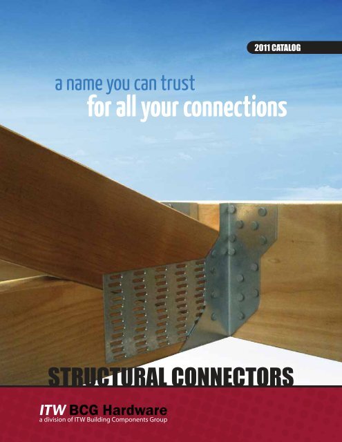
a name you can trust<br />
<strong>for</strong> <strong>all</strong> <strong>your</strong> <strong>connections</strong><br />
STRUCTURAL CONNECTORS
It's time to get more out of the ef<strong>for</strong>ts you put into the design and build process. It's time to shake things up – to look at construction hardware in a whole new light. <strong>ITW</strong> Building<br />
Components For over Group thirty-nine is proud to years, introduce KC a complete ® Metal line Products, of construction Inc. hardware has and remained software solutions the largest based family on our extensive owned engineering manufacturer expertise of - <strong>all</strong> builders designed to structural create more<br />
value <strong>for</strong> you!<br />
hardware. Founded in San Jose, Cali<strong>for</strong>nia in 1970, the company owes it’s longevity in this competitive market to it’s <strong>all</strong>egiance<br />
Building professionals consistently look to component industry experts to supply the critical structural in<strong>for</strong>mation they need to specify hardware - in fact we have been c<strong>all</strong>ing out loads<br />
to to specify customers, and constant stock hangers pursuit <strong>for</strong> more of than new 40 years. and better So while manufacturing this is just the start of techniques, our new brand of and hardware dedication you can rest to producing easy knowing the our experts best product have experience at the to get<br />
the best job done. price. Designing With structural its headquarters <strong>connections</strong> is in the San lifeblood Jose, of what KC we ® Metal do. The addition Products, of our own Inc., line along of hardware with will its <strong>all</strong>ow southern us to spend Cali<strong>for</strong>nia the extra time branch, needed to KC build ® better Metals<br />
<strong>connections</strong> and software solutions that encompass more of the entire structure, to simplify and speed over<strong>all</strong> construction.<br />
South in Riverside, can handle the toughest jobs no matter the size or <br />
And that is just the start! As part of <strong>ITW</strong>, our complete line of construction products offers a unique opportunity to be involved in every major part of the building industry. We now have<br />
the and resources tight to deadlines realign existing we business will earn tools and <strong>your</strong> create the missing links to supply to tie together <strong>your</strong> <strong>all</strong> daily the parts needs. and <strong>all</strong> the The players company’s - to deliver competitive on the promise of attitude BIM and whole and house devotion design. By<br />
working to it’s with product select experts line in ensures and outside that of the we <strong>ITW</strong> will family provide of companies, the best we are product able to offer and a distinctive the best value alternative unmatched by any to get other. the Our job direct done <strong>connections</strong> right, to Cullen and at hardware, the<br />
Paslode/Duofast and other strategic partners have <strong>all</strong>owed us to fast-track a complete line of code approved<br />
right cost <strong>for</strong> you. We will strive to serve you in the best possible way. KC ® construction hardware products - and we have<br />
Metal Products, Inc. and KC ® no intention of slowing down.<br />
Metals South look<br />
For nearly 100 years, our parent company Illinois Tool Works (<strong>ITW</strong>), has been providing game changing end-user and business to business products and services. By staying customer<br />
focused <strong>for</strong>ward we have to continuing become exceedingly to supply good at you, creating our customer valued value. customer, You can be sure with that the we best will bring structural <strong>all</strong> of our industry connectors knowledge <strong>for</strong>ward the industry as we craft can new provide. and better solutions <strong>for</strong><br />
the building industry. Our simple goal is to offer you more - Connections <strong>for</strong> <strong>your</strong> Digital Life.<br />
NOTE: Certain ALL REFERENCES products manufactured IN THIS by KC CATALOG Metal Products, TO “KC Inc. METALS” <strong>for</strong> <strong>ITW</strong> Building OR “KC” Components SHALL Group. APPLY All EQUALLY references in AND this catalog SHALL to REFER "KC Metals" TO KC or "KC" ® METAL sh<strong>all</strong> apply PRODUCTS, equ<strong>all</strong>y and sh<strong>all</strong><br />
refer INC. to AND KC Metal TY-RITE Products, TIMBER Inc., doing FASTENERS, business as KC INC., South DOING Metals. BUSINESS AS KC SOUTH METALS.<br />
EVALUATIONS<br />
wide range of code authorities evaluates KC ® Metals’ SUPERSPEED<br />
A wide range of code authorities evaluates these connectors, including:<br />
®<br />
connectors, including:<br />
ICC - International Code Council<br />
Evaluation Service Report 2929 - Joist Hangers/Panelized Roof Hangers/Joist<br />
and Purlin Hangers/Heavy Structural <strong>Hardware</strong>/<br />
Anchors and Straps/Post Anchors/Post<br />
Caps/Anchors and Clips/Angles/Tie Straps/<br />
Foundation <strong>Hardware</strong><br />
Evaluation Service Report 2860 - W<strong>all</strong> Bracing/Bridging/Coil Strapping<br />
Evaluation Service Report 2930 - Wood I-Joist Hangers/Truss Hangers/Straps<br />
Evaluation Service Report 5033 - KCAB SUPERSPEED Anchor Bolts/Anchor<br />
Downs/Strap Anchors/W<strong>all</strong> Anchors/Retrofit<br />
Connectors<br />
Evaluation Service Report 2860 - Anchor Down Screw Type/Embossed Tie<br />
Straps/Roof Diaphragm Kip Straps<br />
Other Code Acceptance:<br />
City of Los Angeles No. RR24197 and 25209/Fabricators License No. 00986.<br />
Meets the Cali<strong>for</strong>nia Division of Architects (OSA), FHA and HUD Standards.<br />
For easy identification of the company, <strong>all</strong> parts are stamped with ICC<br />
Number, Part Number and/or Series Number/Label and Bar Code.<br />
GAGE TABLE<br />
U.S. Standard Steel Gage Equivalents in Nominal Dimensions 1<br />
GALVANIZED STEEL<br />
GAGE IN DECIMALS 2 APPROXIMATE<br />
IN<br />
FRACTIONS<br />
GALVANIZED STEEL<br />
GAGE IN DECIMALS 2 APPROXIMATE<br />
IN<br />
FRACTIONS<br />
3 — — 3 0.239” (6.0 mm) ¹⁄₄”<br />
7 — — 7 0.179” (4.5 mm) ³⁄₁₆”<br />
10 0.138” (3.5 mm) ¹⁄₈” 10 0.134” (3.4 mm) ¹⁄₈”<br />
11 0.123 (3.1 mm) ¹⁄₈” 11 0.120” (3.0 mm) ¹⁄₈”<br />
12 0.108” (2.7 mm) ³⁄₃₂” 12 0.105” (2.6 mm) ³⁄₃₂”<br />
14 0.078” (2.0 mm) ³⁄₃₂” 14 0.075” (1.9 mm) ¹⁄₁₆”<br />
16 0.063” (1.6 mm) ¹⁄₁₆” 16 0.060” (1.5 mm) ¹⁄₁₆”<br />
18 0.052” (1.3 mm) ¹⁄₁₆” 18 0.048” (1.2 mm) ¹⁄₁₆”<br />
20 0.040” (1.0 mm) ¹⁄₃₂” 20 0.036” (0.9 mm) ¹⁄₃₂”<br />
22 0.034” (0.8 mm) ¹⁄₃₂” 22 0.030” (0.7 mm) ¹⁄₃₂”<br />
1<br />
The actual steel dimensions will vary from nominal dimensions according to industry tolerances<br />
2<br />
mm = millimeters<br />
ENGINEER’S AND ARCHITECTS GUIDE<br />
GENERAL NOTES<br />
1. <strong>ITW</strong> KC <strong>BCG</strong> ® Metal reserves Products, the right Inc. to reserves change specifications, the right to change deign specifications, and models without deign<br />
notice and or models liability <strong>for</strong> without such notice changes. or liability <strong>for</strong> such changes.<br />
2. No No authorization is is made made <strong>for</strong> <strong>for</strong> product product modification. modification. If the If product the product is not is to not the to the<br />
customers’ customers’ requirements requirements or specifications, or specifications, the factory the factory should should be contacted be contacted in time to in<br />
<strong>all</strong>ow time <strong>for</strong> correction to <strong>all</strong>ow <strong>for</strong> or correction replacement. or replacement.<br />
3. Critical Critical fabrication, welding welding and and inspection inspection techniques techniques preclude preclude acceptance acceptance of of<br />
SUPERSPEED® SUPERSPEED connectors ® connectors product product change change or adulteration or adulteration by others by others without without written<br />
permission<br />
written<br />
from<br />
permission<br />
authorized<br />
from<br />
factory<br />
authorized<br />
personnel.<br />
factory<br />
This<br />
personnel.<br />
is necessary<br />
This<br />
to<br />
is<br />
guarantee<br />
necessary<br />
the<br />
to<br />
guarantee the ultimate in quality and product per<strong>for</strong>mance. In the event of<br />
ultimate in quality and product per<strong>for</strong>mance. In the event of product design or<br />
product design or fabrication disparity, contact KC ® Metal Products, Inc.<br />
fabrication disparity, contact <strong>ITW</strong> <strong>BCG</strong> immediately. The factory is not liable <strong>for</strong> cost or<br />
immediately. The factory is not liable <strong>for</strong> cost or per<strong>for</strong>mance of products<br />
per<strong>for</strong>mance of products modified by others.<br />
modified by others.<br />
4. For unusual supporting conditions or loading, excessive wood shrinkage hostile<br />
4. For unusual supporting conditions or loading, excessive wood shrinkage hostile<br />
environment situations or abnormal erection requirements, please provide special<br />
environment situations or abnormal erection requirements, please provide<br />
product detailing and/or discuss with the factory.<br />
special product detailing and/or discuss with the factory.<br />
5. Design loads given are based on the 2006 I-Codes (IBC) and the 2005 National<br />
5. Design loads given are based on the 2006 I-Codes (IBC) and the 2005 National<br />
Design Specifications (N.D.S.). Other code agencies and/or editions of the IBC may<br />
Design Specifications (N.D.S.). Other code agencies and/or editions of the IBC<br />
use different design loads.<br />
may use different design loads.<br />
6. Safe design loads in this catalog are based on the lower value of:<br />
6. Safe design loads in this catalog are based on the lower value of:<br />
A. The ultimate tested load, divided by appropriate safety factor.<br />
A. The ultimate tested load, divided by appropriate safety factor.<br />
B. Load-producing 1/8” deflection.<br />
C. Fastener<br />
B. Load-producing<br />
values in accordance<br />
1/8” deflection.<br />
with the code.<br />
D. Seat-bearing C. Fastener loads values are in based accordance on the with 2006 the IBC. code. All of the design loads have been<br />
per<strong>for</strong>med D. Seat-bearing and documented loads are by based an independent on the 2006 testing IBC. laboratory All of the in design accordance loads have with<br />
the ICC been testing per<strong>for</strong>med standards. and Loads documented deflection by and an seating independent of joist testing hanger laboratory is based in<br />
upon inst<strong>all</strong>ation accordance using with proper the ICC nails testing where standards. required and Loads first-class deflection workmanship. and seating of<br />
7. Unless joist otherwise in hanger noted, is based dimensions upon inst<strong>all</strong>ation are in inches using and proper design nails loads where are in required pounds.<br />
8d, 10d,<br />
and<br />
and<br />
first-class<br />
16d signify<br />
workmanship.<br />
common nails. All reference to nominal lumber sizes relates to<br />
dressed 7. Unless or S4S otherwise dimensions. noted, dimensions are in inches and design loads are in<br />
8. Unless<br />
pounds.<br />
otherwise<br />
8d, 10d,<br />
noted,<br />
and 16d<br />
<strong>all</strong>owable<br />
signify<br />
design<br />
common<br />
loads<br />
nails.<br />
are given<br />
All reference<br />
are <strong>for</strong> use<br />
to nominal<br />
with Group II,<br />
lumber sizes relates to dressed or S4S dimensions.<br />
specific gravity 0.50 <strong>for</strong> Douglas fir-Larch used under dry conditions. Design loads <strong>for</strong><br />
other 8. Unless wood otherwise species must noted, be adjusted <strong>all</strong>owable according design loads to the are code. given are <strong>for</strong> use with<br />
Group II, specific gravity 0.50 <strong>for</strong> Douglas fir-Larch used under dry conditions.<br />
Design loads <strong>for</strong> other wood species must be adjusted according to the code.<br />
9. 9. Wood Wood shear shear is not is not considered considered in the in the loads loads given; given; reduce reduce <strong>all</strong>owable <strong>all</strong>owable design design loads loads<br />
when when wood wood shear shear is limiting. is limiting.<br />
10. All All catalog (code) design loads loads assume assume proper proper inst<strong>all</strong>ation inst<strong>all</strong>ation with with the the specified specified<br />
fasteners fasteners or nails. or nails. Inst<strong>all</strong> Inst<strong>all</strong> fasteners <strong>all</strong> fasteners be<strong>for</strong>e be<strong>for</strong>e loading loading connection. connection. verify whether Verify whether<br />
support the member support dimensions member dimensions can receive can the receive specified the nails. specified nails.<br />
11. For For table table and and ICC ICC uni<strong>for</strong>mity, normal normal loads loads are are basic basic design design values values with with a 0% a 0%<br />
increase increase suitable suitable <strong>for</strong> floor <strong>for</strong> loading. floor loading. Two-month Three-month snow duration snow duration loading <strong>for</strong> loading roofs is <strong>for</strong> 1.15 roofs<br />
times<br />
is<br />
the<br />
1.15<br />
normal<br />
times<br />
load<br />
the<br />
(a<br />
normal<br />
15% increase).<br />
load (a 15%<br />
Maximum<br />
increase).<br />
loads<br />
Maximum<br />
already<br />
loads<br />
include<br />
already<br />
a 25%<br />
include<br />
increase<br />
a 25%<br />
<strong>for</strong><br />
increase<br />
seven-day<br />
<strong>for</strong><br />
construction<br />
seven-day<br />
and<br />
construction<br />
may be used<br />
and<br />
<strong>for</strong><br />
may<br />
roofs<br />
be used<br />
in areas<br />
<strong>for</strong><br />
where<br />
roofs in<br />
there<br />
areas<br />
is<br />
where there is no ground snow. Uplift loads have been increased by 33¹⁄₃%<br />
no ground snow. Uplift loads have been increased by 33¹% where applicable <strong>for</strong> wind<br />
where applicable <strong>for</strong> wind and seismic stresses.<br />
and seismic stresses.<br />
12. Where applicable, “maximum” uplift/tension load values listed indicate a<br />
12. Where applicable, “maximum” uplift/tension load values listed indicate a 33¹%<br />
33¹⁄₃% increase. IBC has not recognized the 60% increases taken by some<br />
increase. IBC has not recognized the 60% increases taken by some manufacturers.<br />
manufacturers. Please contact factory <strong>for</strong> these values.<br />
Please contact factory <strong>for</strong> these values.<br />
13. KC ® Metal Products, Inc. has revised calculated design loads based on the<br />
13. Certain products have revised calculated design loads based on the 2006 IBC<br />
2006 IBC Values. In some cases, the evaluation reports may not reflect<br />
Values. In some cases, the evaluation reports may not reflect the increased values due<br />
the increased values due to lag time in revision of the reports. Evaluation<br />
to lag time in revision of the reports. Evaluation reports may be pending on some items.<br />
reports may be pending on some items.<br />
14. Pneumatic or power-actuated fasteners may deflect and injure the operator or<br />
14. Pneumatic or power-actuated fasteners may deflect and injure the operator<br />
others. Nail guns may be used to inst<strong>all</strong> connectors, provided the correct quantity and<br />
or others. Nail guns may be used to inst<strong>all</strong> connectors, provided the correct<br />
type<br />
quantity<br />
of nails are<br />
and<br />
properly<br />
type of<br />
inst<strong>all</strong>ed<br />
nails are<br />
in<br />
properly<br />
the nails<br />
inst<strong>all</strong>ed<br />
holes. Guns<br />
in the<br />
with<br />
nails<br />
nail<br />
holes.<br />
hole locating<br />
Guns with<br />
mechanisms<br />
nail hole<br />
should<br />
locating<br />
be<br />
mechanisms<br />
used. Follow<br />
should<br />
the manufacturer’s<br />
be used. Follow<br />
instructions<br />
the manufacturer’s<br />
and use the<br />
appropriate instructions safety and equipment. use the appropriate safety equipment.<br />
15.<br />
15. Unless<br />
Unless<br />
otherwise<br />
otherwise<br />
noted,<br />
noted,<br />
bending<br />
bending<br />
steel<br />
steel<br />
in the<br />
in the<br />
field<br />
field<br />
may<br />
may<br />
cause<br />
cause<br />
fractures<br />
fractures<br />
at the<br />
at<br />
bend<br />
the<br />
line. bend Fractured line. steel Fractured will not steel carry will load not and carry must load be and replaced. must be replaced.<br />
16. All references to bolts or machine bolts (MBs) are <strong>for</strong> structural quality through bolts<br />
16. All references to bolts or machine bolts (MBs) are <strong>for</strong> structural quality through<br />
equal<br />
bolts<br />
to or<br />
equal<br />
better<br />
to<br />
than<br />
or better<br />
American<br />
than<br />
Society<br />
American<br />
of Testing<br />
Society<br />
and<br />
of Testing<br />
Materials<br />
and<br />
ASTM<br />
Materials<br />
Standard<br />
ASTM<br />
A307 Standard Grade A. A307 Grade A.<br />
SPECIFICATION:<br />
Items All items sh<strong>all</strong> have sh<strong>all</strong> an have evaluation an evaluation report where report indicated where and indicated be equal and in design,quality be equal in and design,<br />
quality and specifications to those manufactured by KC ® Metals SUPERSPEED<br />
specifications to those manufactured by KC® Metals SUPRSPEED® connectors, San Jose ®<br />
and<br />
connectors, San Jose and Riverside, Cali<strong>for</strong>nia.<br />
Riverside, Cali<strong>for</strong>nia.<br />
2<br />
www.itwbcghardware.com - 800.521.9790<br />
<strong>ITW</strong> <strong>BCG</strong> <strong>Hardware</strong>
EVALUATION INFORMATION November 2011<br />
ICC — International Code Council<br />
of Building Officials<br />
5360 South Workman Mill Road<br />
Whittier, Cali<strong>for</strong>nia 90601<br />
Phone: (562) 699-0543<br />
Fax: (562) 695-4694<br />
www.icc-es.org<br />
Evaluation Service Report Nos. 2929, 2860,<br />
2930, 5033, 2860<br />
DSA — Department of the State Architects<br />
1300 “I” Street, Suite 800<br />
Sacramento, Cali<strong>for</strong>nia 95814<br />
Phone: (916) 445-0783<br />
Fax: (916) 327-3371<br />
(916) 445-3521<br />
www.dsa.dgs.ca.gov<br />
LA City — City of Los Angeles<br />
Department of Building and Safety<br />
411 City H<strong>all</strong><br />
Los Angeles, CA 90012<br />
Phone: (213) 485-2376<br />
Fax: (213) 847-0985<br />
www.ladbs.org<br />
Report Nos. 24197 and 25209/Division 91<br />
Fabricators License No. 00986<br />
The following conditions must be met to receive item evaluation/acceptance on wood hangers and framing devices.<br />
<br />
independent testing laboratory having adequate experience and<br />
equipment to conduct such tests.<br />
<br />
reports must be submitted. With this in<strong>for</strong>mation, the connectors are<br />
designed with a safe, sound load in accordance with the Uni<strong>for</strong>m<br />
Building Code.<br />
<br />
quarterly inspected by an ICC recognized quality control agency.<br />
<br />
CORROSION RESISTANCE<br />
inspected in <strong>all</strong> phases of manufacturing including first piece and inprocess<br />
inspections conducted be<strong>for</strong>e and after painting.<br />
<br />
designation) available upon request. Only prime quality steel is used,<br />
and <strong>all</strong> steel is ordered based on strength, thickness, <strong>for</strong>mability,<br />
weldability and finish.<br />
<br />
All connectors and anchors manufactured by KC® have barcode label and are<br />
the stamped KC ® Metal with the Products, KC® Metal Inc. Products, logo and Inc. the logo model and the designation. model designation.<br />
<br />
Annual evaluation/acceptance payment fee and annual document<br />
examination reexamination required.<br />
KC Three ® Metal corrosion Products, resistance Inc. coatings offers are three offered coatings <strong>for</strong> products <strong>for</strong> products which require<br />
which extra corrosion require resistance. extra corrosion Deterioration resistance. will occur Deterioration more quickly will when occur<br />
more hangers quickly and straps when are hangers exposed and to corrosive straps are environments. exposed to Products corrosive are<br />
environments. available in the standard Products galvanized are available material in or the painted standard with galvanized<br />
gray paint. If<br />
material you require or additional painted with protection, KC ® SUPERSPEED <strong>all</strong> parts are also ® available gray paint. with G-Max If you<br />
(G185) require triple additional zinc coating, protection, hot dip <strong>all</strong> galvanized parts are coating also available or manufactured with<br />
from G-Max stainless (G185) material. triple zinc Fasteners coating, used hot must dip also galvanized be considered coating when or<br />
exposed manufactured to a corrosive from stainless environment. material. Please Fasteners contact the used factory must <strong>for</strong> pricing also<br />
and be considered availability on when these exposed processes. to a corrosive environment. Please<br />
contact the factory <strong>for</strong> pricing and availability on these processes.<br />
Hot Dip Galvanizing:<br />
All products are available with a hot dip<br />
galvanized coating. This coating is applied<br />
after manufacture. The zinc content of the<br />
galvanization process is gener<strong>all</strong>y between<br />
1.1 and 2.3 ounces per square foot of<br />
surface area. The actual thickness will vary<br />
with the material thickness of the part.<br />
This process provides the needed extra<br />
protection <strong>for</strong> adverse weather conditions.<br />
Stainless Steel:<br />
The best protection from adverse<br />
conditions is found in the use of<br />
stainless steel <strong>for</strong> manufacture.<br />
Type 316 stainless steel is used.<br />
It is recommended that stainless<br />
steel fasteners be used in<br />
conjunction with these speci<strong>all</strong>y<br />
manufactured hardware items.<br />
G-MAX Triple Zinc Coating:<br />
The standard coating requirement <strong>for</strong> ICC approved<br />
connectors<br />
The standard<br />
is<br />
coating<br />
(G60) .60<br />
requirement<br />
oz of zinc per<br />
<strong>for</strong> ICC<br />
square<br />
approved<br />
foot of<br />
surface connectors area. is The (G60). standard 60 oz of coating zinc per requirement square foot <strong>for</strong> of<br />
KC surface ® Metal area. Products The standard connectors coating is requirement (G90) .90 oz. <strong>for</strong> of<br />
zinc connectors per square is (G90) foot .90 of surface oz. of zinc area. per This square is a 50% foot of<br />
increase surface area. over This ICC galvanized is a 50% increase requirements. over ICC<br />
G-Max galvanized (G185) requirements. or 3 times the G-Max ICC (G185) coating or requirement. 3 times the<br />
This ICC coating triple zinc requirement. coating is available This triple on zinc many coating items is in<br />
the<br />
available<br />
KCMP<br />
on<br />
product<br />
many items<br />
line.<br />
in the KCMP product line.<br />
FASTENING IDENTIFICATION<br />
TRIANGLE<br />
DIAMOND<br />
SPEED PRONG<br />
SLOTTED<br />
EMBOSSED<br />
Triangle shaped holes<br />
are provided in some<br />
hangers <strong>for</strong> use to<br />
achieve the maximum<br />
load values. Both round<br />
and triangle holes must<br />
be filled in order to<br />
achieve these “max”<br />
values.<br />
Diamond shaped holes<br />
are provided in some<br />
hangers <strong>for</strong> temporarily<br />
holding the fasteners to<br />
the joist or header during<br />
the inst<strong>all</strong>ation process.<br />
Also as optional nailing<br />
<strong>for</strong> increasing uplift.<br />
Speed prongs are<br />
found in many fasteners<br />
to provide faster and<br />
easier inst<strong>all</strong>ation. These<br />
prongs act to hold the<br />
connector in place during<br />
the inst<strong>all</strong>ation process.<br />
Slotted holes <strong>all</strong>ow<br />
easier nailing when<br />
placement conditions<br />
are tight. In some cases,<br />
slotted holes can be<br />
placed in horizont<strong>all</strong>y<br />
(“slant nailing” or<br />
vertic<strong>all</strong>y (“positive angle<br />
nailing”), depending on<br />
<strong>your</strong> requirements<br />
Embossed holes are<br />
used on certain straps<br />
enabling inst<strong>all</strong>ation<br />
with a power activated<br />
gun, <strong>all</strong>owing faster<br />
and less expensive<br />
inst<strong>all</strong>ation. Specify “SS”<br />
SUPERSPEED after the<br />
c<strong>all</strong>out to indicate the<br />
embossed hole pattern.<br />
<strong>ITW</strong> <strong>BCG</strong> <strong>Hardware</strong><br />
www.itwbcghardware.com - 800.521.9790<br />
© 3
PITCH CONVERSION<br />
Roof Slope<br />
Conversion<br />
Chart<br />
If Common Rafter Roof Pitch is . . .<br />
Then Hip/V<strong>all</strong>ey Rafter Roof Pitch<br />
becomes . . .<br />
Rise/Run Slope Rise/Run Slope<br />
1/12 5 1/17 3<br />
90°<br />
80°<br />
70°<br />
60°<br />
DEGREES<br />
2/12 10 2/17 7<br />
3/12 14 3/17 10<br />
50°<br />
4/12 18 4/17 13<br />
5/12 23 5/17 16<br />
6/12 27 6/17 19<br />
7/12 30 7/17 22<br />
8/12 34 8/17 25<br />
9/12 37 9/17 28<br />
10/12 40 10/17 30<br />
11/12 42 11/17 33<br />
12/12 45 12/17 35<br />
Use this conversion table only <strong>for</strong> hip/v<strong>all</strong>ey rafters that are skewed 45° right<br />
or left. All others will cause the slope to change from that listed above. Slope<br />
rounded to the nearest degree<br />
12/12<br />
11/12<br />
10/12<br />
9/12<br />
8/12<br />
40°<br />
7/12<br />
6/12<br />
5/12<br />
4/12<br />
3/12<br />
30°<br />
2/12<br />
1/12<br />
20°<br />
10°<br />
NAIL CONVERSION / SIZES<br />
0/12<br />
0°<br />
Catalog Nail<br />
Replacement Nail<br />
Design Load<br />
Adjustment Factor<br />
16d Common 10d x 1¹⁄₂ 0.64<br />
16d Common 10d Common/12d Common 0.84<br />
16d Common 16d Sinker 0.84<br />
16d Common 16d x 2¹⁄₂ (N16) 1.00<br />
10d Common/12d Common 10d x 1¹⁄₂ 0.77<br />
10d Common/12d Common 16d Sinker 1.00<br />
8d Common 8d x 1¹⁄₂ 0.80<br />
8d x 1¹⁄₂ 8d x 1¹⁄₂ 0.86<br />
10d Hard 10d Common 0.64<br />
10d Hard 10d x 1¹⁄₂ 0.52<br />
16d Hard 10d Hand 0.84<br />
16d Hard 16d Common 0.65<br />
16d Hard 10d Common 0.54<br />
KC Our ® nails Metal and Products, structural nails fasteners and structural have been fasteners developed have as been the developed optimum<br />
as<br />
fasteners<br />
the optimum<br />
<strong>for</strong> connector<br />
fasteners<br />
products.<br />
<strong>for</strong> connector<br />
Special<br />
products.<br />
lengths af<strong>for</strong>d<br />
Special<br />
economy<br />
lengths<br />
of<br />
af<strong>for</strong>d<br />
economy of purchase and inst<strong>all</strong>ation, and depth compatibility with framing<br />
purchase and inst<strong>all</strong>ation, and depth compatibility with framing members.<br />
members. Nail specifications include head size, thickness, steel and shank<br />
Nail specifications include head size, thickness, steel and shank design, and<br />
design, and point configuration to ensure con<strong>for</strong>mity to published values.<br />
point configuration to ensure con<strong>for</strong>mity to published values.<br />
N25 N20L N20 N16 N10 N8<br />
Actual Size<br />
PRODUCT<br />
CODE<br />
REF NO.<br />
DESCRIPTION<br />
METRIC EQUIVALENT<br />
(mm)<br />
FINISH<br />
FASTENERS<br />
PER 50 LBS<br />
CARTON<br />
LIGHT GAGE<br />
DOUG FIR-LARCH/SO PINE<br />
DESIGN LOAD (LBS)<br />
SHEAR (100) GAGE SHEAR (100)<br />
N8 N8 (8d) 10¹⁄₄ ga x 1¹⁄₂” Smooth Shank 3.3 x 38.1 HDG 7600 86 14 105<br />
N10 N10 (10d) 9 ga x 1¹⁄₂” Smooth Shank 3.3 x 38.1 HDG 5900 92 14 112<br />
N16 N16 (16d) 8 ga x 2¹⁄₂” Smooth Shank 4.1 x 63.5 BRIGHT 3150 134 18 187<br />
N20L N20AN (20d) 0.192 x 2¹⁄₈” Annular Ring 4.9 x 54.0 BRIGHT 2750 145 14 174<br />
N20 N20A (20d) .192 x 1³⁄₄” Annular Ring 4.9 x 44.5 BRIGHT 3150 119 14 140<br />
N25 N54A .250 x 2¹⁄₂” Annular Ring 6.4 x 63.5 BRIGHT 1350 167 14 188<br />
10d Common (10d) 0.148 x 3” Annular Ring 3.8 x 76.2 BRIGHT 3350 112 18 158<br />
16d Sinker 0.148 x 3¹⁄₄” Smooth Shank 3.8 x 82.6 GV 3050 112 18 158<br />
12d Common 0.148 x 3¹⁄₄” Smooth Shank 3.8 x 82.6 BRIGHT 3050 112 18 158<br />
16d Common 0.162 x 3¹⁄₂” Smooth 4.1 x 88.9 BRIGHT 4400 134 14 187<br />
10d Hardened 0.148 x 2¹⁄₂” Smooth 3.8 x 63.5 BRIGHT NA 175 12 210<br />
16d Hardened 0.162 x 3¹⁄₂” Smooth 4.1 x 63.5 BRIGHT NA 207 12 245<br />
3 GAGE<br />
4<br />
www.itwbcghardware.com - 800.521.9790<br />
<strong>ITW</strong> <strong>BCG</strong> <strong>Hardware</strong><br />
®
CATEGORY LISTING<br />
November 2011<br />
JOIST HANGERS 8 -18<br />
E......................................Economy Hangers.................................................. 8<br />
S, SR ...............................Standard Hangers/Rough ....................................... 8<br />
SSL, SSR .........................Standard Skewed Left/Right Hangers (45°)............ 8<br />
MSL, MSR .......................Medium Skewed Left/Right Hangers (45°) ............ 8<br />
LS ...................................Light Sloped Hangers .......................................... 10<br />
LSS .................................Light Sloped/Skewed Hangers ............................. 10<br />
SSC .................................Sloped Seat Connectors....................................... 10<br />
STP .................................Standard Truss Plated Hangers ............................ 12<br />
HTP, HTPR .......................Heavy Truss Plated Hangers ................................. 12<br />
HTPTF, HTPTFR ...............Heavy Truss Plated Top Flange Hangers ............... 12<br />
HDTP ...............................Heavy-Duty Truss Plated Hangers ........................ 12<br />
AHU .................................Heavy Truss Plated Hangers ................................13a<br />
KTJC ...............................Heavy-Duty Joist and Truss Hangers ...................13a<br />
HHDTP ............................Heavy Heavy-Duty Truss Plated Hangers .............. 14<br />
HHDTPQ ..........................Heavy Heavy-Duty Truss Plated Hangers<br />
(Drive Screw) ....................................................... 14<br />
AGUS...............................Medium Duty Truss & Joist Hanger .....................15a<br />
H, HR ...............................Heavy Hangers .................................................... 16<br />
HTF, HTFR .......................Heavy Top Flange Hangers ................................... 18<br />
PANELIZED ROOF HANGERS 18 - 20<br />
PH, PHG ..........................Panelized Hangers/Grip ....................................... 18<br />
FH ...................................Formed Hangers .................................................. 20<br />
JOIST AND PURLIN HANGERS 20 - 22<br />
RS, RSO, RSH,<br />
RSG, RSGH ......................Roof Structure Hangers ....................................... 20<br />
R, RA, RH, RHG ...............Roof Hangers ....................................................... 22<br />
TR ...................................Top Mount Hangers ............................................. 22<br />
TRUSS HARDWARE 24 - 28<br />
LHJT ...............................Light Hip/Jack Truss Hangers .............................. 24<br />
LMTH ..............................Light Multiple Truss Hangers ................................ 24<br />
MHJT ..............................Medium Hip/Jack Truss Hangers .......................... 24<br />
MMTH, MMTH-2 .............Multiple, Medium Truss Hangers .......................... 24<br />
MTHTF2, MTHTF2-2........Multiple, Medium Truss Hangers<br />
Top Flange ........................................................... 26<br />
TGH2 (R/L)......................Truss Girder Hangers Skewed<br />
Left/Right (45°).................................................... 26<br />
TGH, TGHH, TGHW ..........Truss Girder Hangers ........................................... 26<br />
ATH .................................Adjustable Truss Hangers .................................... 28<br />
ATHSL, ATHSR ................Adjustable Truss Hangers<br />
Skewed Left/Right (45°) ...................................... 28<br />
ATHI ................................Adjustable Truss Hangers I-Joist .......................... 28<br />
ATHISL, ATHISR ..............Adjustable Truss Hangers<br />
I-Joist Skewed Left/Right (45°)............................ 28<br />
LSC .................................Load Share Clip ..................................................29a<br />
WOOD I-JOIST CONNECTORS 30 - 43<br />
Ordering In<strong>for</strong>mation ................................................................................. 30<br />
Designer and Inst<strong>all</strong>er Instructions .......................................................... 30<br />
Common Inst<strong>all</strong>ation Errors with Use of a Nailer ..................................... 30<br />
Inst<strong>all</strong>ation Errors <strong>for</strong> Top Mount Hangers ............................................... 31<br />
Engineered Wood Product Sizes ............................................................... 31<br />
SUPERSPEED Drive Screws ...................................................................... 31<br />
Face Mount Hangers .................................................................................. 32<br />
Top Mount Hangers .................................................................................... 32<br />
Top Mount Hangers (Shear W<strong>all</strong>s) ............................................................. 33<br />
TR ...................................Top Mount Hangers (Light)................................... 36<br />
TRS .................................Grip Lock to Joist ............................................ 34<br />
MTR ................................Top Mount Hangers (Medium).............................. 37<br />
HTR .................................Top Mount Hangers (Heavy) ................................. 37<br />
RSL, RS/RSI, RSO/RSOI ..Top Mount Hangers ............................................. 38<br />
R/RI, R/RAI, RAU, RH/RHI, RHU,<br />
RM/RMI, RMU .................Roof Hangers Welded Type<br />
(Masonry Uplift) ................................................... 40<br />
SI, MUI ............................U-Type (Universal) Joist Hangers ......................... 42<br />
ISU ..................................Top Mount to Header (Self-Jigging to Header) ........ 34<br />
TRS .................................Top Mount to Header (Grip Lock to Joist) ........... 34<br />
BHV, BHSV ......................Heavy-Duty Hangers (Double/Triple Type) ............ 43<br />
HBHQ ..............................Heavy Beam Hanger (Screw Type) ....................... 43<br />
STEEL STUD HARDWARE 44<br />
SDS .................................Screws................................................................ 44<br />
ST/CA, ST/CAS................Clip Anchors/Skewed ........................................... 44<br />
ST/WA, ST/WAH 14 ........W<strong>all</strong> Anchors ....................................................... 44<br />
ST/AD .............................Anchor Downs ..................................................... 44<br />
ST/R, ST/RS ....................Roof Hangers ....................................................... 44<br />
SKEWED OR SLOPED JOIST HANGERS 45<br />
S .....................................Standard Hangers ................................................ 45<br />
H .....................................Heavy Hangers .................................................... 45<br />
HTF .................................Heavy Top Flange Hangers ................................... 45<br />
R, RA ...............................Roof Hangers/Angled ........................................... 45<br />
RH, RHG ..........................Roof Heavy Hangers/Glulam ................................ 45<br />
RS ...................................Roof Structure Hangers ....................................... 45<br />
RSO .................................Roof Structure Oregon (Uplift) Hangers ................ 45<br />
RSH .................................Roof Structure Heavy Hangers ............................. 45<br />
RSG .................................Roof Structure Glulam Hangers ............................ 45<br />
RSGH ..............................Roof Structure Glulam Heavy Hangers ................. 45<br />
STRUCTURAL HARDWARE SPECIALS 46<br />
Ordering In<strong>for</strong>mation ................................................................................. 46<br />
Hip <strong>Hardware</strong> ............................................................................................. 46<br />
Skewed, Offset or Sloped <strong>Hardware</strong> ......................................................... 46<br />
Truss <strong>Hardware</strong> .......................................................................................... 46<br />
HANGER OPTIONS GENERAL NOTES 47<br />
HEAVY STRUCTURAL HARDWARE 48 - 52<br />
BH, BHS, LBH,<br />
MBH, HBH .......................Beam Hangers ..................................................... 48<br />
SH, SHT, HSHT.................Saddle Hangers/Seismic Ties ............................... 48<br />
HSH .................................Heavy Saddle Hangers ......................................... 50<br />
HHC, HHC3 ......................Heavy Hinge Connectors ...................................... 50<br />
HHCT, HHCM ...................Heavy Hinge Connector Tabs................................ 50<br />
HCTS ...............................Hinge Connector Tie straps .................................. 50<br />
CPT .................................Cross Purlin Ties .................................................. 50<br />
BS, BSH, BST ..................Beam Seats ......................................................... 52<br />
ANCHORS AND STRAPS 52- 54<br />
WA, WAH, WAI, WAL,<br />
WAM, WAW .....................W<strong>all</strong> Anchors/Washers ......................................... 52<br />
ST, GST ...........................Strap Ties/Glulam Strut Ties ................................. 52<br />
DST .................................Drag Strut Ties .................................................... 54<br />
KB ...................................Knee Braces ........................................................ 54<br />
POST CAPS 54 - 58<br />
PC ...................................Post Caps ............................................................ 54<br />
PB, EPB, LEPB4...............Post Beam Caps .................................................. 54<br />
PTC .................................Post Tie Caps ....................................................... 54<br />
MC, HH ............................Mullion Clips/Header Hangers .............................. 56<br />
TCB .................................Truss Clip Bases .................................................. 56<br />
SPT, SPTR, SPTS, SPTD ..Stud Plate Ties .................................................... 56<br />
BCQ, EBCQ, BC, EBC, BCO,<br />
BCOB, BCC, BCT, EBCL ...Beam Caps .......................................................... 58<br />
SC, ESC ...........................Splice Caps ......................................................... 58<br />
POST ANCHORS 60 - 62<br />
HA, HAS, HAQ, HASQ.......Heavy Anchors/Stand-Off ..................................... 60<br />
PA, PAS ...........................Post Anchors/Stand-Off ....................................... 60<br />
PAM, PAMR .....................Post Anchors/Medium Heavy ............................... 62<br />
EA ...................................Elevated Anchors ................................................. 62<br />
AA, AAEL.........................Adjustable Anchors/Economy Long ...................... 62<br />
DA, DAS ..........................Deck Anchors/Stand-Off ...................................... 62<br />
ANCHORS AND CLIPS (WOOD-TO-WOOD) 64 - 66<br />
FA3, FA6, FAL, FALW .......Framing Anchors ................................................. 64<br />
CA, CAS ...........................Clip Anchors/Skewed ........................................... 64<br />
HT ...................................Hurricane Ties ..................................................... 66<br />
TC, TCL, TCD, TCH...........Truss Clips ........................................................... 66<br />
ANGLES AND BRACES 68<br />
LL, ML .............................Light Angles/Medium Angles ................................ 68<br />
ZH ...................................“Z” Hangers (Clips).............................................. 68<br />
T, TH, L, LH ......................Braces................................................................. 68<br />
ANGLES AND ANCHORS 70 - 74<br />
HL, HLG ...........................Heavy Angles/Gussets ......................................... 70<br />
GA ...................................Gusset................................................................. 70<br />
GTH, GTL, GTM ................Girder Ties ........................................................... 70<br />
STA .................................Stair Tread Angles ................................................ 70<br />
SAI, SA, SAT, SAMT, HSA,<br />
CSAI, MSAI .....................Strap Anchors ...................................................... 72<br />
ETAM, ETAH, ETAHH........Embedded Truss Anchors ..................................... 72<br />
HSA, SSAD, SA ................Strap Anchors ...................................................... 74<br />
ANCHOR DOWNS 76 - 80<br />
AD, ADA, ADAG, ADBG ....Anchor Downs ..................................................... 76<br />
ADC .................................Anchor Down Concentric ..................................... 78<br />
ADSTG, ADG....................Screw Type Anchor Downs .................................. 78<br />
SDS .................................SUPERSPEED Drive Screws................................ 80<br />
MSP ................................Mudsill Plate Washers.......................................... 80<br />
BW, BWS, LBW, LBWS.....Bearing Washers (Square).................................... 80<br />
FSTL, FST ........................Floor Strap Ties ................................................... 80<br />
ANCHOR BOLTS AND HOLDERS 82<br />
KCAB...............................SUPERSPEED Anchor Bolts................................. 82<br />
ABC .................................Anchor Bolt Chairs ............................................... 82<br />
SHEAR WALLS 84<br />
SSWA ..............................Anchor Bolt Shear W<strong>all</strong> ........................................ 84<br />
SUPERSPEED EMBOSSED TIE STRAPS 86<br />
TS SS, 3XTS SS, MTS SS, 3XMTS SS,<br />
MTSI SS, MTSC SS .........Tie Straps ............................................................ 86<br />
SUPERSPEED EMBOSSED DIAPHRAGM STRAPS 88<br />
CNS, 3XCNS, CNSI, CNS<br />
KIP, 3X CNS KIP ..............Diaphragm Straps ............................................... 88<br />
CADS...............................Cali<strong>for</strong>nia Anchor Down System<br />
(Anchor Downs, Straps ...................................... 106<br />
TIE STRAPS AND BRACING 90 - 92<br />
TS, TSA, LTSA, LTSI, FHA, HPS,<br />
HTS, MTS, MTSI, MTSC...Tie Straps ............................................................ 90<br />
TW, MTW, MTWC,<br />
HTW, HTWC .....................Twist Straps ........................................................ 90<br />
LS, MS ............................Light/Medium, Straps .........................................91a<br />
WB, WBA ........................W<strong>all</strong> Bracing/Anchors .......................................... 92<br />
XB ...................................Truss Bridging ..................................................... 92<br />
RCS .................................Retrofit Coil Straps .............................................. 92<br />
RS ...................................Rolled Staps .......................................................93a<br />
FOUNDATION HARDWARE 94<br />
MA, MAS .........................Mudsill Anchors/Singleside .................................. 94<br />
LMA, MA4, MA6 ..............Mudsill Anchors “V” Type ..................................... 94<br />
WFT, W ............................Wedge Form Ties/Wedges ................................... 94<br />
SFC .................................Speed Form Clips ................................................ 94<br />
GH, GHD ..........................Girder Hangers .................................................... 94<br />
RETROFIT CONNECTORS 96<br />
RFA .................................Retrofit Foundation Angles ................................... 96<br />
RFP .................................Retrofit Foundation Plates .................................... 96<br />
RFS .................................Retrofit Foundation Straps ................................... 96<br />
RPA .................................Retrofit Foundation Anchors ................................. 96<br />
FJ ....................................Floor Jacks .......................................................... 96<br />
ORNAMENTAL CONNECTORS 98<br />
OA, OS, OHS ....................Angles/Straps...................................................... 98<br />
OL, OLH, OT, OTH .............“L”/”T” Braces..................................................... 98<br />
OH ...................................Hangers............................................................... 98<br />
OBC, OEBC ......................Beam Caps .......................................................... 98<br />
OHA .................................Heavy Anchors ..................................................... 98<br />
SPECIAL AND CUSTOM JOIST HANGERS 100<br />
HNP .................................Hayward Nail Pattern or Uplift Hangers .............. 100<br />
MBHG..............................Masonry Beam Hanger Galvanized .................... 100<br />
RM ..................................Masonry Hangers Concealed <strong>Hardware</strong> ............. 100<br />
Concealed <strong>Hardware</strong> ............................................................................... 100<br />
MISC.: CLIPS, BRACKETS AND ANGLES 101 - 103<br />
FB ...................................Fence Brackets .................................................. 101<br />
CFA, SBS, SBB ................Concrete Form Angles/Shelf Brackets ................ 101<br />
SP ...................................Safety Plates ..................................................... 101<br />
PC ...................................Steel Plywood Clips ........................................... 101<br />
NP, NPA ...........................Nail Plates ......................................................... 102<br />
RPS .................................Retrofit/Rein<strong>for</strong>ced Plate Straps ......................... 102<br />
SB ...................................Stud Braces ....................................................... 102<br />
RR ...................................Rafter Ridge Connectors .................................... 102<br />
FMTSZ .............................TrussLok-Z Screw.............................................. 103<br />
Testing 104 - 105<br />
<strong>ITW</strong> <strong>BCG</strong> <strong>Hardware</strong><br />
www.itwbcghardware.com - 800.521.9790<br />
5
PRO CODE Description Ref No Page<br />
3MTS SS ....... SUPERSPEED Embossed Tie Straps ...............— .....................86<br />
3XCNS .......... SUPERSPEED Embossed Diaphragm Straps ..— .....................88<br />
3XCNS KIP .... SUPERSPEED Embossed Diaphragm Straps ..— .....................88<br />
3XTS SS ........ SUPERSPEED Embossed Tie Straps ...............— .....................86<br />
AA ................. Adjustable Anchor ...........................................AB .....................62<br />
AAEL ............. Adjustable Anchor Long ..................................ABU ...................62<br />
ABC ............... Anchor Bolt Chair ............................................— .....................82<br />
AD ................. Anchor Down ..................................................HD .....................76<br />
ADA ............... Anchor Down ..................................................HDA...................76<br />
ADAG ............ Anchor Down ..................................................HDA...................76<br />
ADBG ............ Anchor Down ..................................................HDA...................76<br />
ADC............... Anchor Down Concentric ................................HDC ..................78<br />
ADG .............. Anchor Down Quick ........................................HDU/HDQ/HHDQ 78<br />
ADSTG .......... Anchor Down Quick ........................................HDU/PHD-SDS ...78<br />
AGUS ............ Heavy-Duty Joist and Truss Hangers ...............— ...................15a<br />
AHU ............... Heavy Duty .....................................................— ...................13a<br />
ATH ............... Adjustable Truss Hanger .................................THA ...................28<br />
ATHI .............. Adjustable Truss Hanger I-Joist .......................THAI ..................28<br />
ATHR ............. Adjustable Truss Hanger .................................THAC .................28<br />
ATHSR/L ....... Adjustable Truss Hanger Skewed ....................THASR/L ............28<br />
BC ................. Beam Cap .......................................................CC .....................58<br />
BCC ............... Beam Cap Centered ........................................CCC ...................58<br />
BCO .............. Beam Cap No Legs .........................................CCO...................58<br />
BCOB ............ Beam Cap O avy ............................................HGLB .................52<br />
BST ............... Beam Seat “T” ................................................GLBT .................52<br />
BW/BWS ....... Bearing Washer (Slotted) .................................BP/BPS..............80<br />
BW-KIT ......... Bearing Washer...............................................BP-KIT ...............80<br />
CA ................. Clip Anchor .....................................................L .......................64<br />
CAD ............... Cali<strong>for</strong>nia Anchor Down System ......................ATS .................106<br />
CAS ............... Clip Anchor Skewable .....................................LS .....................64<br />
CNS ............... Embossed Diaphragm Straps ..........................— .....................88<br />
CNS KIP ........ SUPERSPEED Embossed Diaphragm Straps ..— .....................88<br />
CNSI .............. SUPERSPEED Embossed Diaphragm Straps ..— .....................88<br />
CPT ............... Cross Purlin Tie ...............................................PCT ...................50<br />
CSAI .............. Strap Anchor I-Joist ........................................CPAI ..................72<br />
DA ................ Deck Anchor ...................................................BCO...................62<br />
DAS ............... Deck Anchor Stand Off ....................................APS ...................62<br />
DSTL/R-SDS . Drag Strut Tie..................................................DSCL/R-SDS .....54<br />
E.................... Economy Joist Hanger ....................................LU .......................8<br />
EA ................. Elevated Anchor ..............................................EPB ...................62<br />
EA-12 ............ Elevated Anchor 12 Inch .................................EPB-12..............62<br />
EBC ............... End Beam Cap ................................................ECC ...................58<br />
EBCL ............. End Beam Cap “L” Type ..................................ECCL .................58<br />
EBCO ............. End Beam Cap No Legs ..................................ECCO .................58<br />
EBCOQ .......... End Beam Cap No Legs Quick .........................ECCOQ ..............58<br />
EBCQ ............. End Beam Cap Quick ......................................ECCQ .................58<br />
EPB ............... End Post Beam Cap ........................................ACE ...................54<br />
ESC ............... End Splice Cap ................................................EPC ...................58<br />
ETAH ............. Embedded Truss Anchor Heavy .......................HETA .................72<br />
ETAHH ........... Embedded Truss Anchor Heavy Heavy .............HHETA ...............72<br />
ETAM ............ Embedded Truss Anchor Medium ....................META ................72<br />
FA ................. Framing Anchor ..............................................A .......................64<br />
FAL/FALW ..... Framing Anchor/Lateral W<strong>all</strong> ...........................LTP/RBC ............64<br />
FB ................. Fence Bracket .................................................FB ...................101<br />
FH ................ Formed Hanger ...............................................FN .....................20<br />
FHA ............... Tie Strap .........................................................FHA ...................90<br />
FJ .................. Floor Jack .......................................................J/JP ..................96<br />
FMTSZ .......... TrussLok-Z Screw ...........................................— ...................103<br />
FST ............... Floor Strap Tie ................................................FTA....................80<br />
FSTL ............. Floor Strap Tie Light ........................................LFTA ..................80<br />
GA ................. Gusset Angle ...................................................HGA ...................70<br />
GH ................. Girder Hanger .................................................GH .....................94<br />
GST ............... Glulam Strut Tie ..............................................HSA ...................52<br />
GTH ............... Girder Tiedown Heavy .....................................HGT ...................70<br />
GTL ............... Girder Tiedown Light .......................................LGT ...................70<br />
GTM .............. Girder Tiedown Medium ..................................MGT ..................70<br />
H ................... Heavy Hanger .................................................HU ...............16, 45<br />
HA ................. Heavy Anchor .................................................CB .....................60<br />
HAQ............... Heavy Anchor Quick .......................................CBQ...................60<br />
HAS ............... Heavy Anchor Stand Off ..................................CBS ...................60<br />
HASQ ............ Heavy Anchor Stand Off Quick ........................CBSQ ................60<br />
HBH............... Heavy Beam Hanger .......................................EG .....................48<br />
HBHQ ............ Heavy Beam Hanger Screw Type ....................EGQ ...................43<br />
HCTS ............. Hinge Connector Tie Strap ..............................HCST .................51<br />
HDTP ............. Heavy Duty Truss Plated Hanger .....................HHUS ................12<br />
HH ................. Header Hanger ................................................HH .....................56<br />
HHC ............... Heavy Hinge Connector ...................................HCA ...................50<br />
HHC2M ......... Heavy Hinge Connector ...................................HC2CTA .............50<br />
HHC3 ............. Heavy Hinge Connector ...................................HC3A .................50<br />
HHC3/4M ...... Heavy Hinge Connector ...................................HC4C3TA ...........50<br />
HHC3M ......... Heavy Hinge Connector ...................................HCC3TA .............50<br />
HHC4M ......... Heavy Hinge Connector ...................................HC4CTA .............50<br />
HHCM ........... Heavy Hinge Connector ...................................HCCTA ...............50<br />
HHDTP .......... Heavy Heavy Duty Truss Plated Hanger ...........HGUS ................14<br />
HHDTPQ ........ Heavy Heavy Duty Truss Plated Hanger Quick .HGUSQ ..............14<br />
HL ................. Heavy Angle ....................................................HL .....................70<br />
HPS ............... Heavy Piling Strap ...........................................PS .....................90<br />
HR ................. Heavy Hanger (Reverse) ..................................HUC ...................16<br />
HRQ............... Heavy Hanger Quick(Reverse) .........................HUCQ ................14<br />
HSA ............... Heavy Strap Anchor ........................................HPA/HPAHD .72, 74<br />
HSH ............... Heavy Saddle Hanger ......................................HGLS .................50<br />
HSHT ............. Heavy Saddle Hanger/Seismic Tie ...................HGLST ...............48<br />
HT ................. Hurricane Tie ..................................................H / HCP .............66<br />
HTF ............... Heavy Top Flange Hanger ................................HUTF ...........18, 45<br />
HTFR ............. Heavy Top Flange Hanger (Reverse) ................HUCTF ...............18<br />
HTP/AHU ....... Heavy Truss Plated Hanger..............................HUS ............12,13a<br />
6<br />
www.itwbcghardware.com - 800.521.9790<br />
PRO CODE Description Ref No Page<br />
HTPR ............. Heavy Truss Plated Hanger (Reverse) ..............HUSC ................12<br />
HTPTF ........... Heavy Truss Plated Top Flange Hanger ...........HUSTF ...............12<br />
HTPTFR ......... Heavy Truss Plated Top Flange Hanger<br />
(Reverse) ........................................................HUSCTF .............12<br />
HTR ............... Heavy Top Mount Hanger ................................HIT ....................37<br />
HTS ............... Heavy Tie Strap ...............................................HST ...................90<br />
HTW .............. Heavy Twist Strap ...........................................HTS ...................90<br />
HTWC ............ Heavy Twist Strap Centered ............................HTSC .................90<br />
ISU ................ Hanger I-Joist .................................................IUS ....................34<br />
KB ................. Knee Brace .....................................................VB .....................54<br />
KCAB ............ KC Anchor Bolt ................................................SSTB .................82<br />
KTJC ............. Heavy-Duty Joist and Truss Hangers ...............— ...................13a<br />
L .................... “L” Brace ........................................................L .......................68<br />
LBH ............... Light Glulam Beam Hanger .............................LEG .............46, 48<br />
LBW .............. Light Bearing Washer ......................................LBP ...................81<br />
LBWS ............ Light Bearing Washer Slotted ..........................LBPS .................81<br />
LEPB4 ........... Post Beam Cap ...............................................LCE4 .................54<br />
LH .............. “L” Brace Heavy ..............................................HL .....................68<br />
LHJTR/L ........ Light Hip/Jack Truss Hanger Skewed ..............LTHJR/L.............24<br />
LL .................. Light Angle ......................................................A .......................68<br />
LMA .............. Light Mudsill Anchor .......................................LMA ..................94<br />
LMTH ............ Light Multiple Truss Hanger .............................LTHMA ..............24<br />
LS ................. Light Sloped/Hanger .......................................LSU ...................10<br />
LS ................. Light Strap .....................................................LSTA ...............91a<br />
LSC ............... Load Share Clip ..............................................— ...................29a<br />
LSS ............... Light Sloped/Skewed Hanger ..........................LSSU .................10<br />
LSSAD .......... SUPERSPEED Strap Anchor<br />
Down Embedded ............................................LSTHD ...............74<br />
LSSADRJ ...... SUPERSPEED Strap Anchor Down Rim Joist ..LSTHDRJ ...........74<br />
LTSA ............. Light Tie Strap ................................................LSTA .................90<br />
LTSI ............... Light Tie Strap I-Joist ......................................LSTI ..................90<br />
MA ................ Mudsill Anchor ................................................MA / MAB ..........94<br />
MAS .............. Mudsill Anchor Single-Side .............................MAS ..................94<br />
MBH .............. Medium Beam Hanger ....................................MEG ..................48<br />
MBHG ........... Masonry Beam Hanger ...................................MBHA ..............100<br />
MBHGR/L ...... Masonry Beam Hanger<br />
Skewed Right/Left (45º) ..................................MBHAR/L ........100<br />
MC ................ Mullion Clip .....................................................FC .....................56<br />
MHJT ............ Medium Hip/Jack Truss Hanger ......................THJA .................24<br />
ML ................ Medium Angle .................................................A .......................68<br />
MMTH ........... Medium Multiple Truss Hanger ........................MTHM ...............24<br />
MS ................ Medium Strap .................................................MSTA ..............91a<br />
MSAI ............. Masonry Strap Anchor I-Joist ..........................MPAI .................72<br />
MSC .............. Multiple Seat Connector ..................................MSC ................. —<br />
MSP .............. Mudsill Plate Washer.......................................— .....................80<br />
MSR/L........... Medium Skewed Right/Left Hanger (45º) ........HSUR/L ...............8<br />
MSR/LC ........ Medium Skewed Right/Left Hanger<br />
(45º) (Reverse) ................................................HSUR/LC .............8<br />
MTHTF .......... Multiple Truss Hanger Top Flange ....................MSCPT ..............26<br />
MTHTFN ........ Multiple Truss Hanger Top Flange ....................MSCPTN ............27<br />
MTR .............. Medium Top Mount Hanger .............................MIT ...................37<br />
MTS .............. Medium Tie Strap............................................MST ............86, 90<br />
MTS SS ......... SUPERSPEED Embossed Tie Straps ...............— .....................86<br />
MTSC ............ Tie Strap Countersunk ....................................MSTC ..........86, 90<br />
MTSC SS ....... SUPERSPEED Embossed Tie Straps ...............— .....................86<br />
MTSI ............. Medium Tie Strap I-Joist .................................MSTI ...........86, 90<br />
MTSI SS ........ SUPERSPEED Embossed Tie Straps ...............— .....................86<br />
MTW ............. Medium Twist Strap ........................................MTS ..................90<br />
MTWC ........... Medium Twist Strap Centered .........................MTSC ................90<br />
MUI ............... Medium Hanger I-Joist ...................................MIU ...................42<br />
N ................... Nails ...............................................................N .........................4<br />
NP ................. Nail Plate ........................................................TP ...................102<br />
NPA ............... Nail Plate ........................................................TPA ................102<br />
OA ................. Ornamental Angle ...........................................OHA...................98<br />
OBC ............... Ornamental Beam Cap ....................................OCC...................98<br />
OEBC ............. Ornamental End Beam Cap .............................OECC .................98<br />
OH ................. Ornamental Hanger .........................................OHU ..................98<br />
OHA............... Ornamental Heavy Anchor ...............................OCB...................98<br />
OHS ............... Ornamental Heavy Strap Tie ............................OHS...................98<br />
OL ................. Ornamental “L” Brace .....................................OL .....................98<br />
OLH ............... Ornamental “L” Brace Heavy ...........................OHL ...................98<br />
OS ................. Ornamental Strap Tie ......................................OS .....................98<br />
OT ................. Ornamental “T” Brace .....................................OT .....................98<br />
OTH ............... Ornamental “T” Brace Heavy ..........................OHT ...................98<br />
PA ................. Post Anchor.....................................................PB .....................60<br />
PAM .............. Post Anchor Medium .......................................LCB ...................62<br />
PAS ............... Post Anchor Standoff.......................................PBS ...................60<br />
PB ................. Post Beam Cap ...............................................AC .....................54<br />
PC ................. Post Cap .........................................................BC/BCS .............54<br />
PC ................. Steel Plywood Clip ..........................................PSCL ...............101<br />
PH ................. Panel Hanger ..................................................F .......................18<br />
PHG ............... Panel Hanger Grip Type ...................................F_N ...................18<br />
PHGLTF ......... Panel Hanger Long Top Flange ........................HFN ...................18<br />
PTC ............... Post Tie Cap ....................................................LPC ...................54<br />
R ................... Roof Hanger ....................................................W ..........22, 40, 45<br />
RA ................. Roof Hanger ....................................................WNP/WP 22, 40, 45<br />
RAI ................ Roof Hanger I-Joist .........................................WNPI .................40<br />
RAU ............... Uplift Roof Hanger ...........................................WPU ..................40<br />
RCS ............... Retrofit Coil Strap............................................CS/CMST...........92<br />
RCS-R ........... Retrofit Coil Strap Retail ..................................CS-R .................92<br />
RCSC............. Retrofit Coil Strap Counter Sink .......................CMSTC ..............92<br />
RFA ............... Retrofit Foundation Angle ................................FA / HFA ............96<br />
RFP ............... Retrofit Foundation Plate .................................FAP ...................96<br />
RFS ............... Retrofit Foundation Strap ................................FJA / FSA ..........96<br />
RH ................. Roof Hanger ....................................................HW ........22, 40, 45<br />
RHG............... Roof Hanger Glulam ........................................HW ..............22, 45<br />
ALPHABETICAL LISTING<br />
PRO CODE Description Ref No Page<br />
RHI ................ Roof Hanger I-Joist .........................................HWI ...................40<br />
RHU ............... Uplift Roof Hanger ...........................................HWU ..................40<br />
RI .................. Roof Hanger I-Joist .........................................WI .....................40<br />
RM ................ Masonry Hanger .............................................WM ...........40, 100<br />
RMI ............... Masonry Hanger I-Joist ...................................WMI ..................40<br />
RMU .............. Masonry Hanger (Uplift) ..................................WMU .................40<br />
RPA ............... Retrofit Post Anchor ........................................CBA66 ...............96<br />
RPS ............... Tie Strap .........................................................RPS .................102<br />
RR ................. Rafter Ridge Connectors .................................RR ...................102<br />
RS ................. Roof Structure Hanger ....................................B / LB ....20, 38, 45<br />
RS ................. Rolled Strap ...................................................CS ...................93a<br />
RSG ............... Roof Structure Hanger ....................................GB ................20,45<br />
RSGH ............ Roof Structure Hanger ....................................HGB.............20, 45<br />
RSH ............... Roof Structure Hanger ....................................HHB.............20, 45<br />
RSI ................ Roof Structure Hanger I-Joist ..........................BI ..................... 38<br />
RSL ............... Roof Structure Hanger Light I-Joist .................LBV ...................38<br />
RSO ............... Roof Structure Hanger ....................................HB .........20, 38, 45<br />
RSOI .............. Roof Structure Hanger I-Joist ..........................HBI ....................38<br />
RSV ............... Joist and Purlin Hanger ...................................LBV ...................38<br />
S ................... Standard Hanger .............................................U ...................8, 45<br />
SA ................. Strap Anchor ...................................................PA/PAHD......72, 74<br />
SAI ................ Strap Anchor I-Joist ........................................PAI ....................72<br />
SAMT ............ Strap Anchor Twist Masonry ............................PATM .................72<br />
SB ................. Stud Brace ......................................................SS ...................102<br />
SBB ............... Shelf Bracket Big ............................................SBV .................101<br />
SBS (CFA) ..... Shelf Bracket Sm<strong>all</strong> ........................................CF-R................101<br />
SC ................. Splice Cap ......................................................PC .....................58<br />
SDS ............... SUPERSPEED Drive Screw ............................SDS ...................80<br />
SFC ............... Speed Form Clip .............................................— .....................94<br />
SH ................. Saddle Hanger ................................................GLS ...................48<br />
SHT ............... Saddle Hanger/Seismic Tie .............................GLST .................48<br />
SI .................. Standard Hanger I-Joist ..................................IUT ....................42<br />
SP ................. Safety Plate ....................................................NS ...................101<br />
SPT ............... Stud Plate Tie ..................................................SSP ...................56<br />
SPTD ............. Stud Plate Tie Double ......................................DSP ...................56<br />
SPTH ............. Stud Plate Tie Heavy .......................................SPH ...................56<br />
SPTR ............. Stud Plate Tie (Reverse) ..................................RSP ...................56<br />
SPTS ............. Stud Plate Tie Single .......................................SSP ...................56<br />
SSAD ............ SUPERSPEED Strap Anchor Down<br />
Embedded ......................................................STHD .................74<br />
SSADRJ ........ SUPERSPEED Strap Anchor<br />
Down Embedded Rim Joist .............................STHDRJ .............74<br />
SSC ............... Sloped Seat Connector....................................VPA ...................10<br />
SSR/L............ Standard Skewed Right/Left Hanger (45º) .......SUR/L ..................8<br />
SSW .............. SUPERSPEED Shear W<strong>all</strong> ...............................SSW ................. 84<br />
ST ................. Strap Tie .........................................................SA .................... 52<br />
ST/AD ........... Steel Stud <strong>Hardware</strong> .......................................S/HD .................44<br />
ST/CA ........... Steel Stud <strong>Hardware</strong> .......................................S/L ....................44<br />
ST/CAS ......... Steel Stud <strong>Hardware</strong> .......................................S/LS ..................44<br />
ST/R .............. Steel Stud <strong>Hardware</strong> .......................................S/W ...................44<br />
ST/RS ........... Steel Stud <strong>Hardware</strong> .......................................S/B ....................44<br />
ST/WA .......... Steel Stud <strong>Hardware</strong> .......................................S/LTT20.............44<br />
ST/WAH14 .... Steel Stud <strong>Hardware</strong> .......................................S/HTT14 ............44<br />
STA ............... Stair Tread Angle .............................................TA .....................70<br />
STP ............... Standard Truss Hanger ....................................LUS ...................12<br />
T.................... “T” Brace ........................................................T .......................68<br />
TC ................. Roof Truss Clip ................................................STC ...................66<br />
TCB ............... Truss Clip Base ...............................................TBE ...................56<br />
TCD ............... Roof Truss Clip Double ....................................DTC ...................66<br />
TCH ............... Roof Truss Clip Heavy .....................................HTC ...................66<br />
TCL ............... Roof Truss Clip Long .......................................STCT .................66<br />
TGH ............... Truss Girder Hanger ........................................THGB .................26<br />
TGHH............. Truss Girder Hanger Heavy ..............................THGBH ..............26<br />
TGHR/L ......... Truss Girder Hanger Skewed Right/Left (45º) .THGHR/L ...........26<br />
TGHW ............ Truss Girder Hanger Wrap Around ...................THGW ................26<br />
TH ................. “T” Brace Heavy .............................................HT .....................68<br />
TR ................. Top Mount Hanger ..........................................JB / ITT .......22, 36<br />
TRN ............... Post Frame Hanger .........................................PF .....................22<br />
TS ................. Tie Strap ........................................................ST .....................90<br />
TRS ............... Hanger I-Joist ................................................ITS ....................34<br />
TS SS ............ SUPERSPEED Embossed Tie Straps ...............— .....................86<br />
TSA ............... Tie Strap ........................................................MSTA ................90<br />
TSC ............... Truss Scissor Clip............................................TC .....................56<br />
TW ................ Twist Strap ......................................................TS .....................90<br />
W1 ................ Wedge ...........................................................W1 ....................94<br />
WA ................ W<strong>all</strong> Anchor ....................................................LTT ....................52<br />
WAH .............. W<strong>all</strong> Anchor Heavy ..........................................HTT ...................52<br />
WAI ............... W<strong>all</strong> Anchor I-Joist .........................................LTT/LTTI ............52<br />
WAL .............. W<strong>all</strong> Anchor Light ............................................LTT-B ................52<br />
WAM ............. W<strong>all</strong> Anchor Medium .......................................MTT-B ...............52<br />
WAW ............. W<strong>all</strong> Anchor Washer ........................................RP6 ...................52<br />
WB ................ W<strong>all</strong> Bracing Flat .............................................WB ....................92<br />
WBA .............. W<strong>all</strong> Bracing Angle ..........................................CWB ..................92<br />
WFT .............. Wedge Form Tie ..............................................WT ....................94<br />
XB ................. Tension Bridging .............................................TB ....................92<br />
ZH ................. “Z” Hangers (Clip) ...........................................Z .......................68<br />
<strong>ITW</strong> <strong>BCG</strong> <strong>Hardware</strong>
REFERENCE NUMBER ALPHABETICAL LISTING<br />
November 2011<br />
Ref No PRO CODE Description Page Ref No PRO CODE Description Page Ref No PRO CODE Description Page<br />
A ...................... LL, ML ................... Angle ..................................68<br />
A34/A35 ........... FA3/FA6 ................ Anchor ................................64<br />
AB .................... AA ......................... Post Base ............................62<br />
ABU .................. AAEL ..................... Post Base ............................62<br />
AC .................... PB ......................... Post Cap .............................54<br />
APS .................. DAS ....................... Base ...................................62<br />
ATS ................... CADS ..................... Tie-Down System ..............106<br />
B ...................... RS ......................... Hanger ......................20,38,45<br />
BC/BCS ............. PC ......................... Cap/Base ............................54<br />
BCO .................. DA ......................... Base ...................................62<br />
BI...................... RSI ........................ Hanger ................................58<br />
BP/BPS ............. BW/BWS ............... Bearing Plate (Slotted) .........80<br />
CB .................... HA ......................... Column Base .......................60<br />
CBQ .................. HAQ ....................... Column Base .......................60<br />
CBS .................. HAS ....................... Column Base .......................60<br />
CBSQ ................ HASQ..................... Column Base .......................60<br />
CC .................... BC ......................... Column Cap ........................58<br />
CCQ .................. BCQ ....................... Column Cap ........................58<br />
CF-R ................. CFA8 ..................... Form Angle/Shelf Bracket ..101<br />
CMST ............... RCS ....................... Strap ...................................92<br />
CMSTC ............. RCSC ..................... Coiled Strap ........................92<br />
CPAI .................. CSAI ...................... Purlin Anchor .......................72<br />
CS .................... RCS/RS ................. Strap ...................................92<br />
CWB ................. WBA ...................... W<strong>all</strong> Bracing ........................92<br />
DSC .................. DST ....................... Drag Strut Connector ...........54<br />
DSP .................. SPTD ..................... Stud Plate Tie (Double) ........56<br />
DTC .................. TCD ....................... Roof Truss Clip ....................66<br />
ECC .................. EBC ....................... Column Cap ........................58<br />
ECCQ ................ EBCQ ..................... Column Cap ........................58<br />
ECCU ................ EBCU ..................... Column Cap ........................58<br />
EG .................... HBH ....................... Hanger ................................48<br />
EGP .................. HBHP ..................... Hanger ................................48<br />
EPB .................. EA ......................... Post Base ............................62<br />
EPC .................. ESC ....................... Post Cap .............................58<br />
F ....................... PH ......................... Hanger ................................18<br />
FA ..................... RFA ....................... Foundation Anchor ..............96<br />
FAP ................... RFP ....................... Foundation Plate .................96<br />
FB..................... FB .......................... Fence Bracket ...................101<br />
FC..................... MC ......................... Framing Clip ........................56<br />
FHA .................. FHA ....................... Strap Tie .............................90<br />
FJA ................... RFS ....................... Anchor ................................90<br />
FN .................... PHG ....................... Hanger ................................18<br />
FSA................... RFS ....................... Anchor ................................96<br />
FTA ................... FST ........................ Floor Tie Anchor ..................80<br />
GB .................... RSG ....................... Hanger ..........................20, 45<br />
GH .................... GH ......................... Hanger ................................94<br />
GLB .................. BS ......................... Beam Seat ..........................52<br />
GLBT ................ BST ....................... Beam Seat ..........................52<br />
GLS .................. SH ......................... Hanger ................................48<br />
GLT ................... BH ......................... Hanger ..........................46, 48<br />
GLTV ................. BHV ....................... Hanger ................................43<br />
H ...................... HT.......................... Hurricane Ties .....................66<br />
HANGER ............ Options ................. Options ...............................47<br />
HB .................... RSO ....................... Hanger ....................20, 38, 45<br />
HBI ................... RSOI ...................... Hanger ................................38<br />
HCA .................. HHC ....................... Hinge Connector..................50<br />
HCP .................. HT.......................... Hip Corner Plate ..................66<br />
HCSTR .............. HCTS ..................... Strap ...................................51<br />
HD/HDA ............ AD/ADA<br />
ADAG/ADBG ......... Holdown .............................76<br />
HDU .................. ADSTG/ADG .......... Holdown ..............................78<br />
HDC .................. ADC ....................... Concentric Holdown ............78<br />
HDQ .................. ADG ....................... Holdown ..............................78<br />
HETA ................. ETAH ..................... Truss Anchor .......................72<br />
HFA ................... RFA ....................... Hanger ................................96<br />
HFN .................. PHG_LTF ............... Hanger ................................18<br />
HGA .................. GA ......................... Gusset Angle .......................70<br />
HGB .................. RSGH ..................... Hanger ..........................20, 45<br />
HGLB ................ BSH ....................... Beam Seat ..........................52<br />
HGLS ................ HSH ....................... Hanger ................................50<br />
HGLT ................. BHS ....................... Hanger ................................48<br />
HGLTV ............... BHSV ..................... Hanger ................................43<br />
HGT .................. GTH ....................... Girder Tiedown ....................70<br />
HGUQ ................ HHDTPQ ................ Girder Truss Hanger .............14<br />
<strong>ITW</strong> <strong>BCG</strong> <strong>Hardware</strong><br />
HGUS ................ HHDTP/AGUS ........ Hanger .........................14,13a<br />
HH .................... HH ......................... Hanger ................................56<br />
HHB .................. RSH ....................... Hanger ..........................20, 45<br />
HHETA .............. ETAHH ................... Truss Anchor .......................72<br />
HHDQ ............... ADG ....................... Heavy Holdown ...................78<br />
HHUS ................ HDTP ..................... Hanger ................................12<br />
HIT.................... HTR ....................... Hanger ................................37<br />
HL .................... HL .......................... Angle ..................................70<br />
HPA .................. HAS ....................... Purlin Anchor .......................60<br />
HPAHD .............. HSA ....................... Holdown ........................72, 74<br />
HSA .................. GST ....................... Strap ...................................52<br />
HST .................. HTS ....................... Strap ...................................84<br />
HSUR/HSUL ...... MSR/MSL ............. Hanger ..................................8<br />
HTC .................. TCH ....................... Heavy Truss Clip ..................66<br />
HTS .................. HTW ...................... Twist Strap ..........................90<br />
HTSC ................ HTWC .................... Twist Strap (Center) .............90<br />
HTT .................. WAH ...................... Tension Tie ..........................52<br />
HU .................... H ............................ Hanger ..........................16, 45<br />
HUS .................. HTP/AHU ............... Hanger .........................12,13a<br />
HUSC ................ HTPR ..................... Hanger ................................12<br />
HUSTF .............. HTPTF ................... Hanger ................................12<br />
HUTF ................ HTF........................ Hanger ..........................18, 45<br />
HW ................... RH/RHG................. Hanger ....................22, 40, 45<br />
HWU ................. RHU/RHGU ............ Hanger ....................22, 37, 40<br />
ITS .................... TRS ....................... Hanger (I-Joist) ...................34<br />
ITT .................... TR.......................... Hanger (I-Joist) .............22, 36<br />
IUT .................... ISU ........................ Hanger (I-Joist) ...................34<br />
IUS ................... ISU ........................ Hanger (I-Joist) ...................34<br />
JB ..................... TR.......................... Hanger ..........................22, 36<br />
L ANGLE ........... CA ......................... Angle ..................................64<br />
L STRAP TIE ...... L ............................ Strap Tie .............................68<br />
LB..................... RS ......................... Hanger ....................20, 38, 45<br />
LBP/LPBS ......... LBW/LBWS ........... Light Bearing Plate (Slotted) 81<br />
LBV ................... RSL ....................... Hangers ..............................38<br />
LCB .................. PAM ...................... Column Base .......................62<br />
LCE4 ................. LEPB4 ................... Post Cap .............................54<br />
LEG................... LBH ....................... Hanger ..........................46, 48<br />
LFTA ................. FSTL ...................... Floor Tie Anchor ..................80<br />
LGT................... GTL........................ Girder TieDown ...................70<br />
LMA .................. LMA ...................... Mudsill Anchor ....................94<br />
LPC................... PTC ....................... Post Cap .............................54<br />
LS ..................... CAS ....................... Angle ..................................64<br />
LSSU ................ LSS ....................... Hanger ................................10<br />
LSTA ................. LTSA/LS ............... Strap Tie .............................90<br />
LSTHD .............. LSSAD................... Holdown ..............................74<br />
LSTI .................. LTSI ....................... Strap Tie .............................90<br />
LSU .................. LS .......................... Hanger ................................10<br />
LTHJ ................. LHJT ..................... Hanger ................................24<br />
LTHMA .............. LMTH .................... Hanger ................................24<br />
LTP ................... FAL ........................ Framing Anchor ...................64<br />
LTT/LTTI ............ WA/WAI ................ Tension Tie ..........................52<br />
LU..................... E ............................ Hanger ..................................8<br />
LUS .................. STP ....................... Hanger ................................12<br />
MA.................... MA ........................ Mudsill Anchor ....................94<br />
MAS ................. MAS ...................... Mudsill Anchor ....................94<br />
MBHA ............... MBHG .................... Masonry Hanger ................100<br />
MEG ................. MBH ...................... Hanger ................................48<br />
META ................ ETAM .................... Truss Anchor .......................68<br />
MGT ................. GTM ...................... Girder Tiedown ....................72<br />
MIT ................... MTR ...................... Hanger ................................37<br />
MIU ................... MUI ....................... Hanger ................................42<br />
MPAI ................. MSAI ..................... Purlin Anchor (I-Joist) ..........72<br />
MSCPT ............. MTHTF .................. Hanger ................................26<br />
MST .................. MTS ...................... Strap Tie .......................86, 90<br />
MSTA ................ TSA/MS ................ Strap Tie .............................90<br />
MSTC ............... MTSC .................... Strap Tie .......................86, 90<br />
MSTI ................. MTSI ..................... Strap Tie (I-Joist) ...........86, 90<br />
MTHM/MTHM-2 MMTH/MMTH-2 ... Hanger ................................24<br />
MTS .................. MTW ..................... Twist Strap ..........................90<br />
MTSC ............... MTWC ................... Twist Strap (Center) .............90<br />
MTT .................. WAM ..................... Tension Tie ..........................52<br />
NAILS ............... NAILS .................... Nails .....................................4<br />
NS/NSP ............. SP.......................... Nail Stopper ......................101<br />
Ornamentals ..... Ornamentals ........ Ornamental .........................98<br />
PA ..................... SA ......................... Holdown ........................72, 74<br />
PA/PATM ........... SA/SAMT .............. Purlin Anchor .......................72<br />
PAHD ................ SA ......................... Holdown ........................72, 74<br />
PAI .................... SAI ........................ Purlin Anchor (I-Joist)..........72<br />
PAT ................... SAT ....................... Purlin Anchor Twist ..............72<br />
PB .................... PA.......................... Post Base ............................60<br />
PBS .................. PAS ....................... Post Base ............................60<br />
PC .................... SC ......................... Post Cap .............................58<br />
PCT .................. CPT ....................... Purlin Cross Tie ...................50<br />
PF ..................... TRN ....................... Hanger ................................22<br />
PHD .................. ADSTG .................. Holdown ..............................78<br />
PS .................... HPS ....................... Strap ...................................90<br />
PSCL ................ PC ......................... Sheathing Clip ...................101<br />
RBC .................. FALW..................... Anchor ................................64<br />
RP .................... WAW ..................... Washer................................52<br />
RPS .................. RPS ....................... Strap Tie ...........................102<br />
RR .................... RR ......................... Connector .........................102<br />
RSP .................. SPTR ..................... Stud Plate Tie ......................56<br />
SA .................... ST .......................... Strap ...................................48<br />
SBV .................. SBB ....................... Shelf Bracket ....................101<br />
SDS .................. SDS,FM ................. Screw .................................80<br />
SP .................... SPT ....................... Stud Plate Tie ......................56<br />
SPH .................. SPTH ..................... Stud Plate Tie ......................56<br />
SS .................... SB ......................... Stud Shoe .........................102<br />
SSP .................. SPTS ..................... Stud Plate Tie Single ...........56<br />
SSW ................. SSW ...................... Shear W<strong>all</strong> ...........................84<br />
ST..................... TS .......................... Strap Tie .............................90<br />
STC .................. TC .......................... Roof Truss Clip ....................66<br />
STCT ................ TCL ........................ Roof Truss Clip ....................66<br />
STHD ................ SSAD ..................... Holdown ..............................74<br />
SUR/SUL ........... SSR/SSL ............... Hanger ..................................8<br />
T ....................... T ............................ Strap Tie .............................68<br />
TA ..................... STA ....................... Staircase Angle ...................70<br />
TB .................... XB ......................... Tension Bridging .................92<br />
TBE................... TCB ....................... Truss Enhancer ...................56<br />
TC .................... TSC ....................... Truss Connector ..................56<br />
THA .................. ATH ....................... Hanger ................................28<br />
THAC ................ ATHR ..................... Hanger ................................28<br />
THAI ................. ATHI ...................... Hanger (I-Joist) ...................28<br />
THASR/L ........... ATHSR/L ............... Truss Hanger .......................28<br />
THGAR/L ........... TGHR/L ................. Hanger ................................26<br />
THGB ................ TGH ....................... Hanger ................................26<br />
THGBH .............. TGHH ..................... Hanger ................................26<br />
THGW ............... TGHW .................... Hanger ................................26<br />
THJA................. MHJT .................... Hanger ................................24<br />
TP/TPA .............. NP/NPA ................. Tie Plate ............................102<br />
TS..................... TW ......................... Twist Strap ..........................90<br />
U ...................... S ............................ Hanger ............................8, 45<br />
VB .................... KB ......................... Knee Brace .........................54<br />
VPA ................... SSC ....................... Connector ...........................10<br />
W...................... R ............................ Hanger ....................22, 40, 45<br />
WB ................... WB ........................ W<strong>all</strong> Bracing ........................92<br />
WM ................... RM ........................ Hanger ........................40, 100<br />
WMU ................ RMU ...................... Hanger ................................40<br />
WNP ................. RA ......................... Hanger ....................22, 40, 45<br />
WP.................... RAI ........................ Hanger ................................40<br />
WPU ................. RAU ....................... Hanger ................................40<br />
WT .................... WFT ....................... Wedge Form Tie ..................94<br />
Z ....................... ZH .......................... Clip .....................................68<br />
7<br />
www.itwbcghardware.com - 800.521.9790
JOIST HANGERS<br />
E<br />
ECONOMY JOIST HANGERS<br />
Design Features . . combine greater strength<br />
with maximum economy. SUPERSPEED prongs<br />
secure E hangers to header <strong>for</strong> fast, easy nailing.<br />
2 x 4 to 2 x 14.<br />
Material . . 18 ga. galvanized steel.<br />
Special . . economical price and ease-of-use<br />
make these an ideal hanger <strong>for</strong> the do-it-<strong>your</strong>self<br />
market.<br />
E210<br />
S<br />
SR<br />
STANDARD JOIST HANGERS<br />
(ROUGH)<br />
Design Features . . provide proper balance<br />
between load-carrying capacity of hanger and the<br />
joist it supports. Hanger configuration changes <strong>for</strong><br />
heavy-duty S66 and S610.<br />
2xs, 3xs, 4xs, 6xs, double 2xs<br />
and triple 2xs . . also available on special order <strong>for</strong><br />
rough beam sizes.<br />
R to stock no.<br />
(Example: SR26)<br />
Material . . 16 ga. galvanized steel. Meets<br />
specifications <strong>for</strong> schools and public buildings.<br />
Loads . . can be increased with the use of 16d<br />
nails in header <strong>for</strong> S24, S26 and S210. See<br />
Economy hangers <strong>for</strong> load specifications.<br />
Skewed and Sloped Hangers . . are available,<br />
specify angle (67¹⁄₂° max.) and whether left or<br />
right, up or down. Due to the infinite variety of<br />
custom orders, skewed hangers and sloped<br />
hangers are not code evaluated. Design loads of<br />
the nearest equivalent hanger should be used as<br />
a general guide, subject to specific engineering<br />
design.<br />
Top View - Skewed Left<br />
Skewed Left<br />
Typical Design <strong>for</strong> S24,<br />
S26, S210 and S214<br />
SSL<br />
SSR<br />
MSL<br />
MSR<br />
STANDARD SKEWED HANGERS (45°)<br />
MEDIUM SKEWED HANGERS (45°)<br />
Design Features . . standard and medium<br />
skewed hangers are offered to promote further<br />
standardization and construction economies, and<br />
to provide compatibility with the SUPERSPEED<br />
lline of S standard and H heavy joist hangers.<br />
2xs, 3xs, 4xs and double 2xs.<br />
SSL/SSR – 16 ga. galvanized steel.<br />
MSL/MSR – 14 ga. galvanized steel.<br />
Loads . . larger seat-bearing and designed direct<br />
nailing provide proper inst<strong>all</strong>ation of <strong>all</strong> nails into<br />
joist hangers.<br />
Special . . skewed hangers are labor savers. No<br />
angle butt-cuts are required. Reversed flanges are<br />
available in the SSL/SSR and MSL/MSR hangers<br />
furnished with one flange turned in while the other<br />
remains out.<br />
SSL210<br />
MSR<br />
SSL410R<br />
(Reversed Flange)<br />
8<br />
www.itwbcghardware.com - 800.521.9790<br />
<strong>ITW</strong> <strong>BCG</strong> <strong>Hardware</strong>
JOIST HANGERS<br />
www.kcmetals.com<br />
November 2011<br />
E<br />
For Product Substitutions . . . the ONLY APPROVED EQUAL<br />
PRODUCT<br />
CODE<br />
REF NO<br />
JOIST SIZE<br />
DIMENSIONS (INCHES) NAIL SCHEDULE (HEADER) DESIGN LOAD<br />
10D<br />
16D<br />
A D W H HEADER JOIST<br />
NORMAL LBS MAX LBS NORMAL LBS MAX LBS<br />
UPLIFT<br />
LBS<br />
E24 LU24 2 x 4 to 2 x 6 1¹⁄₈ 1¹⁄₂ 1⁹⁄₁₆ 3 4-16d 2-10d x 1¹⁄₂ 450 560 535 670 250<br />
E26 LU26 2 x 6 to 2 x 10 1¹⁄₈ 1¹⁄₂ 1⁹⁄₁₆ 4³⁄₄ 6-16d 4-10d x 1¹⁄₂ 670 840 805 1005 500<br />
E28 LU28 2 x 8 to 2 x 12 1¹⁄₈ 1¹⁄₂ 1⁹⁄₁₆ 6¹⁄₄ 8-16d 6-10d x 1¹⁄₂ 895 1120 1070 1340 750<br />
E210 LU210 2 x 10 to 2 x 14 1¹⁄₈ 1¹⁄₂ 1⁹⁄₁₆ 7⁄ 10-16d 6-10d x 1¹⁄₂ 1120 1400 1340 1675 750<br />
BONUS LOADS WITH 16D<br />
NAILS<br />
E210<br />
For Product Substitutions . . . the ONLY APPROVED EQUAL<br />
PRODUCT ®<br />
DIMENSIONS (INCHES) NAIL SCHEDULE DESIGN LOAD<br />
REF NO JOIST SIZE<br />
CODE<br />
A D W H HEADER JOIST NORMAL LBS MAX LBS<br />
UPLIFT LBS<br />
S24 U24 2 x 4 1¹⁄₈ 1¹⁄₂ 1⁹⁄₁₆ 3 4-10d 2-10d x 1¹⁄₂ 450 565 255<br />
S26 U26 2 x 6 to 2 x 10 1¹⁄₈ 1¹⁄₂ 1⁹⁄₁₆ 4³⁄₄ 6-10d 4-10d x 1¹⁄₂ 680 850 505<br />
S210 U210 2 x 6 to 2 x 14 1¹⁄₈ 1¹⁄₂ 1⁹⁄₁₆ 7¹³⁄₁₆ 10-10d 6-10d x 1¹⁄₂ 1130 1415 760<br />
S214 U214 2 x 14 to 2 x 16 1¹⁄₈ 2 1⁹⁄₁₆ 10 12-16d 8-10d x 1¹⁄₂ 1355 1695 1265<br />
S34 U34 3 x 4 to 3 x 6 1¹⁄₈ 2 2⁹⁄₁₆ 3³⁄₈ 4-16d 2-10d x 1¹⁄₂ 540 675 300<br />
S36 U36 3 x 6 to 3 x 10 1¹⁄₈ 2 2⁹⁄₁₆ 5³⁄₈ 8-16d 4-10d x 1¹⁄₂ 1080 1350 605<br />
S310 U310 3 x 10 to 3 x 14 1¹⁄₈ 2 2⁹⁄₁₆ 8⁷⁄₈ 14-16d 6-10d x 1¹⁄₂ 1890 2365 905<br />
S314 U314 3 x 14 to 3 x 16 1¹⁄₈ 2 2⁹⁄₁₆ 10³⁄₈ 16-16d 6-10d x 1¹⁄₂ 2160 2700 905<br />
S44 U44 4 x 4 to 4 x 6 1¹⁄₈ 2 3⁹⁄₁₆ 2⁷⁄₈ 4-16d 2-10d 540 675 300<br />
S46 U46 4 x 6 to 4 x 10 1¹⁄₈ 2 3⁹⁄₁₆ 4⁷⁄₈ 8-16d 4-10d 1080 1350 605<br />
S410 U410 4 x 10 to 4 x 14 1¹⁄₈ 2 3⁹⁄₁₆ 8³⁄₈ 14-16d 6-10d 1890 2365 905<br />
S414 U414 4 x 14 to 4 x 16 1¹⁄₈ 2 3⁹⁄₁₆ 10 16-16d 6-10d 2160 2700 905<br />
S66 U66 6 x 6 to 6 x 8 1¹⁄₈ 2 5¹⁄₂ 5 8-16d 4-10d 1080 1350 605<br />
S610 U610 6 x 10 1¹⁄₈ 2 5¹⁄₂ 8¹⁄₂ 14-16d 6-10d 1890 2365 905<br />
S24-2 U24-2 (2) 2 x 4 to (2) 2 x 6 1¹⁄₈ 2 3¹⁄₈ 3 4-16d 2-10d 540 675 300<br />
S26-2 U26-2 (2) 2 x 6 to (2) 2 x 10 1¹⁄₈ 2 3¹⁄₈ 5 8-16d 4-10d 1080 1350 605<br />
S210-2 U210-2 (2) 2 x 10 to (2) 2 x 14 1¹⁄₈ 2 3¹⁄₈ 8 14-16d 6-10d 1890 2365 905<br />
S26-3 U26-3 (3) 2 x 6 to (3) 2 x 10 1¹⁄₈ 2 4¹¹⁄₁₆ 5 8-16d 4-10d 1080 1350 605<br />
S210-3 U210-3 (3) 2 x 10 to (3) 2 x 14 1¹⁄₈ 2 4¹¹⁄₁₆ 8¹⁄₂ 14-16d 6-10d 1890 2365 905<br />
S210<br />
S<br />
SR<br />
For Product Substitutions . . . the ONLY APPROVED EQUAL<br />
DIMENSIONS (INCHES) NAIL SCHEDULE DESIGN LOAD<br />
PRODUCT<br />
UPLIFT<br />
REF NO<br />
JOIST SIZE<br />
CODE<br />
A D W H HEADER JOIST NORMAL LBS MAX LBS LBS<br />
SSL/SSR24 SUL/SUR24 2 x 4 1¹⁄₈ 1³⁄₈ 1⁹⁄₁₆ 3¹⁄₈ 4-16d 4-10d x 1¹⁄₂ 540 675 505<br />
SSL/SSR26 SUL/SUR26 2 x 6 to 2 x 10 1¹⁄₈ 1³⁄₈ 1⁹⁄₁₆ 5 6-16d 6-10d x 1¹⁄₂ 810 1015 760<br />
SSL/SSR210 SUL/SUR210 2 x 10 to 2 x 14 1¹⁄₈ 1³⁄₈ 1⁹⁄₁₆ 8¹⁄₈ 10-16d 10-10d x 1¹⁄₂ 1350 1690 1265<br />
SSL/SSR214 SUL/SUR214 2 x 14 to 2 x 16 1¹⁄₈ 1³⁄₈ 1⁹⁄₁₆ 10 12-16d 12-10d x 1¹⁄₂ 1620 2025 1520<br />
SSL/SSR36 SUL/SUR36 3 x 6 to 3 x 10 1¹⁄₄ 2³⁄₁₆ 2⁹⁄₁₆ 5¹⁄₄ 8-16d 4-16d x 2¹⁄₂ 1080 1350 720<br />
SSL/SSR310 SUL/SUR310 3 x 10 to 3 x 14 1¹⁄₄ 2³⁄₁₆ 2⁹⁄₁₆ 9 14-16d 6-16d x 2¹⁄₂ 1890 2365 1080<br />
SSL/SSR314 SUL/SUR314 3 x 14 to 3 x 16 1¹⁄₄ 2³⁄₁₆ 2⁹⁄₁₆ 13 18-16d 8-16 x 2¹⁄₂ 2430 3040 1440<br />
SSL/SSR46 SUL/SUR46 4 x 6 to 4 x 10 1¹⁄₄ 2³⁄₁₆ 3⁹⁄₁₆ 4³⁄₄ 8-16d 4-16d 1080 1350 720<br />
SSL/SSR410 SUL/SUR410 4 x 10 to 4 x 14 1¹⁄₄ 2³⁄₁₆ 3⁹⁄₁₆ 8¹⁄₂ 14-16d 6-16d 1890 2365 1080<br />
SSL/SSR414 SUL/SUR414 4 x 14 to 4 x 16 1¹⁄₄ 2³⁄₁₆ 3⁹⁄₁₆ 12¹⁄₂ 18-16d 8-16d 2430 3040 1440<br />
MSL/MSR36 HSUL/HSUR36 3 x 6 to 3 x 10 1¹⁄₄ 2³⁄₁₆ 2⁹⁄₁₆ 5¹⁄₄ 12-16d 4-16d x 2¹⁄₂ 1630 2040 720<br />
MSL/MSR310 HSUL/HSUR310 3 x 10 to 3 x 14 1¹⁄₄ 2³⁄₁₆ 2⁹⁄₁₆ 9 20-16d 6-16d x 2¹⁄₂ 2720 3400 1080<br />
MSL/MSR314 HSUL/HSUR314 3 x 14 to 3 x 16 1¹⁄₄ 2³⁄₁₆ 2⁹⁄₁₆ 13 26-16d 8-16d x 2¹⁄₂ 3535 4420 1440<br />
MSL/MSR46 HSUL/HSUR46 4 x 6 to 4 x 10 1¹⁄₄ 2³⁄₁₆ 3⁹⁄₁₆ 4³⁄₄ 12-16d 4-16d 1630 2040 720<br />
MSL/MSR410 HSUL/HSUR410 4 x 10 to 4 x 14 1¹⁄₄ 2³⁄₁₆ 3⁹⁄₁₆ 8¹⁄₂ 20-16d 6-16d 2720 3400 1080<br />
MSL/MSR414 HSUL/HSUR414 4 x 14 to 4 x 16 1¹⁄₄ 2³⁄₁₆ 3⁹⁄₁₆ 12¹⁄₂ 26-16d 8-16d 3535 4420 1440<br />
SSL/SSR26-2 SUL/SUR26-2 (2) 2 x 6 to (2) 2 x 10 1¹⁄₄ 2³⁄₁₆ 3¹⁄₈ 4¹⁵⁄₁₆ 8-16d 4-16d x 2¹⁄₂ 1080 1350 720<br />
SSL/SSR210-2 SUL/SUR210-2 (2) 2 x 10 to (2) 2 x 14 1¹⁄₄ 2³⁄₁₆ 3¹⁄₈ 8¹¹⁄₁₆ 14-16d 6-16d x 2¹⁄₂ 1890 2365 1080<br />
SSL/SSR214-2 SUL/SUR214-2 (2) 2 x 14 to (2) 2 x 16 1¹⁄₄ 2³⁄₁₆ 3¹⁄₈ 12¹¹⁄₁₆ 18-16d 8-16d x 2¹⁄₂ 2430 3040 1440<br />
MSL/MSR26-2 HSUL/HSUR26-2 (2) 2 x 6 to (2) 2 x 10 1¹⁄₄ 2³⁄₁₆ 3¹⁄₈ 4¹⁵⁄₁₆ 12-16d 4-16d x 2¹⁄₂ 1630 2040 720<br />
MSL/MSR210-2 HSUL/HSUR210-2 (2) 2 x 10 to (2) 2 x 14 1¹⁄₄ 2³⁄₁₆ 3¹⁄₈ 8¹¹⁄₁₆ 20-16d 6-16d x 2¹⁄₂ 2720 3400 1080<br />
MSL/MSR214-2 HSUL/HSUR214-2 (2) 2 x 14 to (2) 2 x 16 1¹⁄₄ 2³⁄₁₆ 3¹⁄₈ 12¹¹⁄₁₆ 26-16d 8-16d x 2¹⁄₂ 3535 4420 1440<br />
SSR214<br />
SSL<br />
SSR<br />
MSL<br />
MSR<br />
<strong>ITW</strong> <strong>BCG</strong> <strong>Hardware</strong><br />
www.itwbcghardware.com - 800.521.9790<br />
9
LS<br />
LIGHT SLOPED HANGERS<br />
Design Features . . used on existing structures<br />
to increase strength <strong>for</strong> the attachment of joists<br />
to headers. Slip the hanger into place and adjust<br />
the seat (sloped either up or down). Use the hole<br />
in the bottom of the seat to set the hanger to the<br />
joist. Complete nailing to the header flanges or<br />
use <strong>for</strong> new construction needs. These hangers<br />
offer complete inst<strong>all</strong>ation flexibility be<strong>for</strong>e, during<br />
or after joists are erected.<br />
2xs<br />
Material . . 18 ga. galvanized steel.<br />
Loads . . larger seat-bearing and designed direct<br />
nailing provide proper inst<strong>all</strong>ation of <strong>all</strong> nails into<br />
joist hangers.<br />
Special . . the LS eliminates slope hanger mixups<br />
and delays (any slope up or down, to and<br />
including, ¹²⁄₁₂ pitch).<br />
LS210<br />
LSS<br />
LIGHT SLOPED/SKEWED HANGERS<br />
Design Features . . combination sloped<br />
skewed hangers offer further standardization<br />
and construction economy. They also provide<br />
compatibility with the SUPERSPEED line of S<br />
standard joist hangers. LSS hangers can be used<br />
to connect rafters to ridge beams in vaulted roof<br />
structures.<br />
2xs, 3xs, 4xs, double 2x-s and<br />
wood I-joist sizes.<br />
Material . . 18 ga., 16 ga., and 14 ga. galvanized<br />
steel.<br />
Loads . . larger seat-bearing and designed direct<br />
nailing provide proper inst<strong>all</strong>ation of <strong>all</strong> nails into<br />
joist hangers.<br />
Special . . LSS eliminates skewed and sloped<br />
hanger mix-ups and delays (any slope up or<br />
down, to and including, a ¹²⁄₁₂ pitch and any skew<br />
right or left up to 45°).<br />
Ordering/Specifying In<strong>for</strong>mation . .The LSS5.12<br />
must be factory skewed 0° to 45°. It may be field<br />
sloped to 45°. (LSS4.12 and LSS3510-2 are<br />
similar)<br />
A Flange<br />
Configurations of some models<br />
may differ from those shown.<br />
LSS210<br />
Slotted Holes Are<br />
Provided <strong>for</strong> Skewable<br />
Field Bending Application<br />
SSC<br />
SLOPED SEAT CONNECTORS<br />
Design Features . . <strong>all</strong>ow fastening of solid and<br />
wood I-joists to the plate at any slope from 1:12<br />
to 6:12. The SSC eliminates the need <strong>for</strong> costly<br />
rafter notching, bevel plates and toe-nailing.<br />
Inst<strong>all</strong> twelve nails to the plate and four to the<br />
joist.<br />
Material . . 18 ga. galvanized steel.<br />
Special . . the SSC was developed <strong>for</strong> wood<br />
I-joist beams to eliminate the need <strong>for</strong> bird cuts in<br />
the bottom chord.<br />
SSC2<br />
10<br />
www.itwbcghardware.com - 800.521.9790<br />
<strong>ITW</strong> <strong>BCG</strong> <strong>Hardware</strong>
November 2011<br />
For Product Substitutions . . . the ONLY APPROVED EQUAL<br />
LS<br />
PRODUCT<br />
CODE<br />
JOIST SIZE<br />
DIMENSIONS (INCHES) NAIL SCHEDULE DESIGN LOAD/ SLOPE ONLY<br />
WIDTH HEIGHT HEADER JOIST NORMAL LBS<br />
MAXIMUM<br />
LBS<br />
UPLIFT<br />
LBS<br />
LS26 2 X 6 1⁹⁄₁₆ 5 6-10d 7-10d x 1¹⁄₂ 670 835 835<br />
LS28 2 X 8 1⁹⁄₁₆ 6³⁄₄ 8-10d 9-10d x 1¹⁄₂ 895 1005 1005<br />
LS210 2 X 10 1⁹⁄₁₆ 8¹⁄₂ 10-10d 11-10d x 1¹⁄₂ 1120 1400 1390<br />
LS210<br />
For Product Substitutions . . . the ONLY APPROVED EQUAL<br />
DIMENSIONS<br />
DESIGN LOAD (LBS)<br />
PRODUCT<br />
JOIST<br />
REF NO MATERIAL<br />
(INCHES)<br />
“A” NAIL SCHEDULE<br />
CODE<br />
SIZE<br />
FLANGE<br />
SLOPE ONLY SKEW ONLY UPLIFT<br />
WIDTH HEIGHT HEADER JOIST NORMAL MAXIMUM NORMAL MAXIMUM LBS<br />
LSS26 LSU26 18 1¹⁄₂ 1⁹⁄₁₆ 4⁷⁄₈ 1⁹⁄₁₆ 6-10d 5-10d x 1¹⁄₂ 670 835 670 840 635<br />
LSS28 LSSU28 18 1¹⁄₂ 1⁹⁄₁₆ 7¹⁄₈ 1⁹⁄₁₆ 10-10d 5-10d x 1¹⁄₂ 1005 1005 985 985 635<br />
LSS210 LSSU210 18 1¹⁄₂ 1⁹⁄₁₆ 8¹⁄₂ 1⁹⁄₁₆ 10-10d 9-10d x 1¹⁄₂ 1120 1400 1120 1390 1140<br />
LSS25 LSSUI25 18 1³⁄₄ 1¹³⁄₁₆ 8¹⁄₂ 1⁹⁄₁₆ 10-10d 9-10d x 1¹⁄₂ 1120 1400 1120 1390 1140<br />
LSS2.06 LSSUI2.06 18 2 2¹⁄₁₆ 8¹⁄₂ 1³⁄₄ 10-10d 7-10d x 1¹⁄₂ 1110 1390 995 1205 730<br />
LSS2.1 LSSU2.1 18 2¹⁄₁₆ 2¹⁄₈ 8¹⁄₂ 1³⁄₄ 10-10d 7-10d x 1¹⁄₂ 1110 1390 995 1205 730<br />
LSS35 LSSIU35 18 2⁵⁄₁₆ 2³⁄₈ 8¹⁄₂ 1⁵⁄₈ 10-10d 7-10d x 1¹⁄₂ 1110 1390 995 1205 730<br />
LSS310 LSSUH310 16 2¹⁄₂ 2⁹⁄₁₆ 8¹⁄₂ 3¹⁄₈ 18-16d 12-10d x 1¹⁄₂ 2295 2295 1600 1600 1150<br />
LSS210-2 LSSU210-2 16 3 3¹⁄₈ 8¹⁄₂ 2⁷⁄₈ 18-16d 12-10d x 1¹⁄₂ 2430 3035 1625 1625 1150<br />
LSS410 LSSU410 16 3¹⁄₂ 3⁹⁄₁₆ 8¹⁄₂ 2⁵⁄₈ 18-16d 12-10d x 1¹⁄₂ 2430 3035 1625 1625 1150<br />
LSS4.12 LSSU4.12 14 4 4¹⁄₈ 9 2¹⁄₄ 24-16d 16-10d x 1¹⁄₂ 3215 4020 2300 2300 1150<br />
LSS4.28 LSSU4.28 14 4¹⁄₈ 4¹⁄₄ 9 2³⁄₈ 24-16d 16-10d x 1¹⁄₂ 3215 4020 2300 2300 1150<br />
LSS3510-2 LSSU3510-2 14 4³⁄₄ 4³⁄₄ 8⁷⁄₈ 3⁵⁄₈ 24-16d 16-10d x 1¹⁄₂ 3215 4030 2300 2300 1150<br />
LSS5.12 LSSU5.12 14 5 5¹⁄₈ 9 2¹⁄₄ 24-16d 16-10d x 1¹⁄₂ 3215 4030 2300 2300 1150<br />
LSS28<br />
LSS<br />
Inst<strong>all</strong>ation Sequence<br />
Step 1<br />
Nail hanger to joist. Inst<strong>all</strong> the seat<br />
nail first.<br />
Step 2<br />
Skew flange to <strong>for</strong>m acute angle. The other flange should<br />
then be bent back. Form hanger to fit <strong>your</strong> skewed angle.<br />
Step 3<br />
Attach hanger to the header. Nail the acute angle<br />
side first. Nails must be inst<strong>all</strong>ed at an angle.<br />
LSS5.12<br />
Hanger Shown<br />
Skewed Right<br />
PRODUCT<br />
CODE<br />
REF NO<br />
For Product Substitutions . . . the ONLY APPROVED EQUAL<br />
DIMENSIONS (INCHES) NAIL SCHEDULE DESIGN LOAD UPLIFT<br />
LBS<br />
W L PLATE RAFTER NORMAL LBS MAX LBS<br />
SSC2 VPA2 1⁹⁄₁₆ 3¹⁄₂ 12-10d 4-10d x 1¹⁄₂ 1430 1790 250<br />
SSC25 VPAI25 1¹³⁄₁₆ 3¹⁄₂ 12-10d 4-10d x 1¹⁄₂ 1430 1790 250<br />
SSC35 VPAI35 2³⁄₈ 4¹⁄₂ 12-10d 4-10d x 1¹⁄₂ 1430 1790 250<br />
SSC3 VPA3 2⁹⁄₁₆ 4¹⁄₂ 12-10d 4-10d x 1¹⁄₂ 1430 1790 250<br />
SSC4 VPA4 3⁹⁄₁₆ 5¹⁄₂ 12-10d 4-10d x 1¹⁄₂ 1430 1790 250<br />
SSC<br />
Inst<strong>all</strong>ation Sequence<br />
“A”<br />
Flange<br />
“B”<br />
Flange<br />
Required Pitch<br />
10d x 1¹⁄₂”<br />
Common<br />
10d<br />
Common<br />
Step 1<br />
Nail top nails to plate first. Second,<br />
Inst<strong>all</strong> nails to top plate (outside w<strong>all</strong>)<br />
at a slight angle to prevent splitting.<br />
Step 2<br />
Adjust joist rafter with a<br />
hammer to seat “B” flange to<br />
the right pitch.<br />
10d<br />
Common<br />
Step 3<br />
Nail “B” Flange nails in nail<br />
holes, straight down to lock<br />
the required pitch.<br />
Step 4<br />
Use 10d x 1¹⁄₂ nails <strong>for</strong> the joist<br />
rafter (4) to prevent splitting. Nail<br />
at slight angle.<br />
SSC2<br />
<strong>ITW</strong> <strong>BCG</strong> <strong>Hardware</strong><br />
www.itwbcghardware.com - 800.521.9790<br />
11
STP<br />
HTP<br />
HTPR<br />
STANDARD TRUSS<br />
PLATED HANGERS<br />
Design Features . . provide proper balance<br />
between load-carrying capacity of hanger and<br />
the truss it supports.<br />
2xs, 3xs, 4xs, double 2xs, and<br />
triple 2xs.<br />
Material . . 18 ga. galvanized steel.<br />
Loads . . seat dimension (see table) provides<br />
solid larger seat-bearing area. New higher loads<br />
possible with only common nails.<br />
Special . . greater strength combined with<br />
economical price and ease-of-nailing make<br />
these an ideal hanger <strong>for</strong> the competitive<br />
construction trade.<br />
Skewed and Sloped Hangers . . not available<br />
in STP series. See SSR/SSL or S series<br />
hangers, pages 8 and 9.<br />
HEAVY TRUSS<br />
PLATED HANGERS<br />
Design Features . . constant dimensional<br />
accuracy and precision controlled 90° angles<br />
assure proper joist bearing (flat seat) and header<br />
connection alignment. Two design styles are<br />
available with standard or reversed flanges<br />
(turned inward).<br />
4xs and double 2xs.<br />
Material . . 14 ga. galvanized steel.<br />
Loads . . 2” seat dimension provides solid<br />
larger seat-bearing area. New higher loads<br />
possible with only<br />
common nails.<br />
Skewed and Sloped Hangers . . not available<br />
in HTP series. See MSL/MSR series, pages 8<br />
and 9 or H series, pages 16 and 17.<br />
“Slant Nailing”<br />
(Toe Nailing)<br />
Drive Full Length<br />
Common Nails at 45°<br />
into Joist <strong>for</strong> Header<br />
Connection<br />
STP210<br />
HTP412<br />
“Slant Nailing”<br />
(Toe Nailing)<br />
Drive Full Length<br />
Common Nails at 45°<br />
into Joist <strong>for</strong> Header<br />
Connection<br />
HTPTF HEAVY TRUSS PLATED<br />
HTPTFR<br />
TOP FLANGE HANGERS<br />
Design Features . . with the addition of a<br />
top flange, the heavy truss hanger meets or<br />
exceeds specifications <strong>for</strong> schools and public<br />
buildings, where strength, support, and safety<br />
are prime requirements. Two design styles are<br />
available with standard or reversed flanges<br />
(turned inward).<br />
Joist sizes . . 4xs and double 2xs.<br />
Material . . 14 ga. galvanized steel.<br />
Special . . greater strength combined with<br />
economical price and ease-of-nailing make<br />
these an ideal hanger <strong>for</strong> the competitive<br />
construction trade.<br />
Skewed and Sloped Hangers . . not available in<br />
HTPTF series. See HTF series, pages 18 and 19.<br />
HTPTF414<br />
“Slant Nailing”<br />
(Toe Nailing)<br />
Drive Full Length<br />
Common Nails at 45°<br />
into Joist <strong>for</strong> Header<br />
Connection<br />
HDTP<br />
HEAVY-DUTY TRUSS<br />
PLATED HANGERS<br />
Design Features . . HDTP universal facemount<br />
hanger is designed <strong>for</strong> wood plate<br />
trusses and heavily loaded members.<br />
Joist sizes . . 2xs, 4xs, double 2xs, triple 2xs,<br />
and quad 2xs.<br />
Material . . HDTP2x – 16 ga. galvanized steel.<br />
HDTP4x, 2x-2 – 14 ga. galvanized steel.<br />
Loads . . 3” seat dimension provides the<br />
greatest bearing area of any hanger available.<br />
Super capacity design loads are the highest of<br />
any universal face-mounted hanger.<br />
Special . . larger header flange and joist seat<br />
make this hanger very easy to inst<strong>all</strong> with<br />
common nails.<br />
Skewed and Sloped Hangers . . (see page 43).<br />
HDTP210<br />
“Slant Nailing”<br />
(Toe Nailing)<br />
Drive Full Length<br />
Common Nails at 45°<br />
into Joist <strong>for</strong> Header<br />
Connection<br />
12<br />
www.itwbcghardware.com - 800.521.9790<br />
<strong>ITW</strong> <strong>BCG</strong> <strong>Hardware</strong>
PRODUCT<br />
CODE<br />
REF NO<br />
JOIST SIZE<br />
For Product Substitutions . . . the ONLY APPROVED EQUAL<br />
DIMENSIONS (INCHES) NAIL SCHEDULE DESIGN LOAD UPLIFT<br />
LBS<br />
D W H HEADER JOIST NORMAL LBS MAX LBS<br />
STP24 LUS24 2 x 4 1³⁄₄ 1⁹⁄₁₆ 3 4-10d 2-10d 640 800 465<br />
STP26 LUS26 2 x 6, 8 1³⁄₄ 1⁹⁄₁₆ 4³⁄₄ 6-10d 4-10d 1055 1320 930<br />
STP28 LUS28 2 x 8, 10 1³⁄₄ 1⁹⁄₁₆ 6⁵⁄₈ 8-10d 4-10d 1275 1595 930<br />
STP210 LUS210 2 x 10, 12, 14 1³⁄₄ 1⁹⁄₁₆ 7¹³⁄₁₆ 10-10d 4-10d 1500 1875 930<br />
STP24-2 LUS24-2 (2) 2 x 4 2 3¹⁄₈ 3¹⁄₈ 4-16d 2-16d 765 880 465<br />
STP26-2 LUS26-2 (2) 2 x 6, 8 2 3¹⁄₈ ⁄₈ 8-16d 4-16d 1450 1810 1140<br />
STP28-2 LUS28-2 (2) 2 x 8 2 3¹⁄₈ 7 12-16d 6-16d 2215 2765 1710<br />
STP28-3 LUS28-3 (3) 2 x 8, 10, 12 2 4⁵⁄₈ 6¹⁄₄ 12-16d 6-16d 2215 2765 1710<br />
STP210-2 LUS210-2 (2) 2 x 10, 12 2 3¹⁄₈ 9 16-16d 8-16d 3025 3780 2070<br />
STP214-2 LUS214-2 (2) 2 x 14 2 3¹⁄₈ 10¹⁵⁄₁₆ 20-16d 10-16d 3150 3940 2585<br />
STP44 LUS44 4 x 4 2 3⁹⁄₁₆ 3 4-16d 2-16d 765 880 465<br />
STP46 LUS46 4 x 6, 8 2 3⁹⁄₁₆ 4³⁄₄ 8-16d 4-16d 1450 1810 1140<br />
STP48 LUS48 4 x 8 2 3⁹⁄₁₆ 6³⁄₄ 12-16d 6-16d 2215 2765 1710<br />
STP410 LUS410 4 x 10, 12, 14 2 3⁹⁄₁₆ 8³⁄₄ 16-16d 8-16d 3025 3780 2070<br />
STP414 LUS414 4 x 12, 14 2 3⁹⁄₁₆ 10³⁄₄ 20-16d 10-16d 3150 3940 2585<br />
www.kcmetals.com<br />
November 2011<br />
STP<br />
STP210<br />
PRODUCT<br />
CODE<br />
REF NO<br />
JOIST SIZE<br />
For Product Substitutions . . . the ONLY APPROVED EQUAL<br />
DIMENSIONS (INCHES) NAIL SCHEDULE DESIGN LOAD UPLIFT<br />
LBS<br />
D W H HEADER JOIST NORMAL LBS MAX LBS<br />
HTP26-2 HUS26-2 (2) 2 x 6 2 3¹⁄₈ 5³⁄₁₆ 8-16d 4-16d 1550 1940 1080<br />
HTP28-2 HUS28-2 (2) 2 x 8 2 3¹⁄₈ 7³⁄₁₆ 12-16d 6-16d 2325 2905 1620<br />
HTP210-2 HUS210-2 (2) 2 x 10 2 3¹⁄₈ 9³⁄₁₆ 16-16d 8-16d 3105 3880 2160<br />
HTP212-2 HUS212-2 (2) 2 x 12 2 3¹⁄₈ 10³⁄₄ 20-16d 10-16d 3875 4040 2560<br />
HTP46 HUS46 4 x 6 2 3⁹⁄₁₆ 5 8-16d 4-16d 1550 1940 1080<br />
HTP48 HUS48 4 x 8 2 3⁹⁄₁₆ 7 12-16d 6-16d 2325 2905 1620<br />
HTP410 HUS410 4 x 10 2 3⁹⁄₁₆ 9 16-16d 8-16d 3105 3880 2160<br />
HTP412 HUS412 4 x 12 2 3⁹⁄₁₆ 10⁹⁄₁₆ 20-16d 10-16d 3875 4040 2560<br />
HTP<br />
HTPR<br />
HTP412<br />
PRODUCT<br />
CODE<br />
REF NO<br />
For Product Substitutions . . . the ONLY APPROVED EQUAL<br />
JOIST SIZE<br />
DIMENSIONS (INCHES) NAIL SCHEDULE DESIGN LOAD UPLIFT<br />
LBS<br />
D W H TF HEADER JOIST NORMAL LBS MAX LBS<br />
HTPTF26-2 HUS26-2TF (2) 2 x 6 2 3¹⁄₈ 5³⁄₈ 2¹⁄₂ 10-16d 4-16d 2900 3015 1080<br />
HTPTF<br />
HTPTFR<br />
HTPTF28-2 HUS28-2TF (2) 2 x 8 2 3¹⁄₈ 7¹⁄₄ 2¹⁄₂ 12-16d 6-16d 3500 3900 1620<br />
HTPTF210-2 HUS210-2TF (2) 2 x 10 2 3¹⁄₈ 9¹⁄₄ 2¹⁄₂ 16-16d 8-16d 3590 4200 2160<br />
HTPTF212-2 HUS212-2TF (2) 2 x 12 2 3¹⁄₈ 11¹⁄₈ 2¹⁄₂ 20-16d 10-16d 4475 5000 2855<br />
HTPTF214-2 HUS214-2TF (2) 2 x 14 2 3¹⁄₈ 13¹⁄₈ 2¹⁄₂ 24-16d 10-16d 4790 5315 2855<br />
HTPTF46 HUS46TF 4 x 6 2 3⁹₁₆ 5³⁄₈ 2¹⁄₂ 10-16d 4-16d 2900 3015 1080<br />
HTPTF48 HUS48TF 4 x 8 2 3⁹₁₆ 7¹⁄₄ 2¹⁄₂ 12-16d 6-16d 3500 3900 1620<br />
HTPTF410 HUS410TF 4 x 10 2 3⁹₁₆ 9¹⁄₄ 2¹⁄₂ 16-16d 8-16d 3590 4200 2160<br />
HTPTF412 HUS412TF 4 x 12 2 3⁹₁₆ 11¹⁄₈ 2¹⁄₂ 20-16d 10-16d 4475 5000 2855<br />
HTPTF414 HUS414TF 4 x 14 2 3⁹₁₆ 13¹⁄₈ 2¹⁄₂ 24-16d 10-16d 4790 5315 2855<br />
HTPTF414<br />
PRODUCT<br />
CODE<br />
REF NO<br />
For Product Substitutions . . . the ONLY APPROVED EQUAL<br />
DIMENSIONS (INCHES) NAIL SCHEDULE DESIGN LOAD<br />
JOIST SIZE<br />
D W H HEADER JOIST NORMAL LBS MAX LBS<br />
UPLIFT<br />
LBS<br />
HDTP<br />
HDTP26 HUS26 2 X 6, 8 3 1⁵⁄₈ 5¹⁄₈ 14-16d 6-16d 2565 3205 1620<br />
HDTP28 HUS28 2 X 8, 10 3 1⁵⁄₈ 7 22-16d 8-16d 3585 3775 2160<br />
HDTP210 HUS210 2 X 10, 12 3 1⁵⁄₈ 9 30-16d 10-16d 3775 4025 2855<br />
HDTP26-2 HHUS26-2 (2) 2 X 6 truss 3 3⁵⁄₁₆ 5 14-16d 6-16d 2580 3225 1620<br />
HDTP28-2 HHUS28-2 (2) 2 X 8 truss 3 3⁵⁄₁₆ 7 22-16d 8-16d 3885 4885 2160<br />
HDTP210-2 HHUS210-2 (2) 2 x 10 truss 3 3⁵⁄₁₆ 9 30-16d 10-16d 5190 5945 2855<br />
HDTP210-3 HHUS210-3 (3) 2 x 10 truss 3 4¹¹⁄₁₆ 9 30-16d 10-16d 5190 5945 2855<br />
HDTP210-4 HHUS210-4 (4) 2 x 10 truss 3 6¹⁄₈ 9 30-16d 10-16d 5190 5945 2855<br />
HDTP46 HHUS46 4 x 6 truss 3 3⁵⁄₈ 5⁄ 14-16d 6-16d 2580 3225 1620<br />
HDTP48 HHUS48 2 x 8 truss 3 3⁵⁄₈ 7 22-16d 8-16d 3885 4885 2160<br />
HDTP410 HHUS410 4 x 10 truss 3 3⁵⁄₈ 9 30-16d 10-16d 5190 5945 2855<br />
HDTP210<br />
<strong>ITW</strong> <strong>BCG</strong> <strong>Hardware</strong><br />
www.itwbcghardware.com - 800.521.9790<br />
13
KTJC37<br />
HEAVY DUTY JOIST AND TRUSS<br />
HANGERS<br />
Design Features . . KTJC37 universal facemount<br />
hanger is designed <strong>for</strong> wood plate<br />
trusses and heavily loaded members.<br />
Joist sizes . . 2xs, 4xs, douoble 2xs,<br />
triple 2xs,6x and 8xs.<br />
PBL or LVL sizes . . KTJC37 available in<br />
2 3 /4” and 7 1 /4” widths.<br />
Glulam sizes . . KTJC37 available in<br />
3 1 /8” and 5 1 /8” widths.<br />
Material . . KTJC37 16 ga. galvanized steel.<br />
Loads . . 4” and 5” seat dimension provides<br />
greatest bearing area of any hanger available.<br />
Super capacity design loads are the highest of<br />
any universal face-mounted hanger.<br />
Special . . larger header flange and joist seat<br />
make this hanger very easy to inst<strong>all</strong> with<br />
common nails.<br />
AHU<br />
MEDIUM DUTY TRUSS & JOIST<br />
HANGER<br />
2 3 /4” seat depth<br />
Joist sizes . . available <strong>for</strong> single, double,<br />
and 4x joist sizes<br />
Material . . AHU 18 ga. galvanized steel.<br />
2 1 4 "<br />
5 1 2"<br />
2 3 4 " AHU26<br />
1 9<br />
16"<br />
2 1 4 "<br />
8 1 2"<br />
3 9<br />
16"<br />
2 3 4 " AHU410<br />
13a<br />
www.itwbcghardware.com - 800.521.9790<br />
<strong>ITW</strong> <strong>BCG</strong> <strong>Hardware</strong>
November 2011<br />
ALLOWABLE LOADS<br />
PRODUCT<br />
CARRYING CARRIED<br />
REF NO<br />
CODE<br />
MEMBER MEMBER 0 0 1 0 -60 0 61 0 -67.5 0<br />
KTJC37 (MIN) TJC37 4-8dx1-1/2 4-8dx1-1/2 340 300 320<br />
KTJC37 (MAX) TJC37 6-8dx1-1/2 6-8dx1-1/2 580 485 425<br />
KTJC37<br />
WEIGHT = .39 lbs<br />
Spruce Pine Fir (0.42 Specific Gravity)<br />
HANGER DIMENSION COMMON NAIL TYPE FASTNERS ALLOWABLE DOWNWARD LOADS ALLOWABLE UPWARD LOADS<br />
PRODUCT SUPPORTED PRODUCT CLEAR OVERALL OVERALL<br />
LOAD DURATION FACTOR LOAD DURATION FACTOR<br />
CODE MEMBER GAUGE<br />
JOIST JOIST HEADER JOIST<br />
WIDTH HEIGHT DEPTH<br />
SIZE QTY SIZE QTY<br />
(in) (in) (in)<br />
1 1.15 1.25 1.6 1 1.15 1.25 1.6<br />
AHU26 1 1/2 18 1 9/16 5 1/2 2 3/4 0.148"x1.5" 8 0.162"x3.5" 24 2565 2685 2765 3050 810 930 1010 1295<br />
AHU28 1 1/2 18 1 9/16 6 1/2 2 3/4 0.148"x1.5" 12 0.162"x3.5" 24 2890 3150 3270 3695 1215 1395 1520 1945<br />
AHU210 1 1/2 18 1 9/16 8 1/2 2 3/4 0.148"x1.5" 16 0.162"x3.5" 24 2890 3320 3610 4345 1620 1860 2025 2590<br />
AHU26-2 3 18 3 7/16 5 1/2 2 3/4 0.148”x3.0” 8 0.162"x3.5" 24 2890 3320 3350 3350 810 930 1010 1295<br />
AHU28-2 3 18 3 7/16 6 1/2 2 3/4 0.148"x3.0" 8 0.162"x3.5" 24 2890 3320 3610 4375 1215 1395 1520 1945<br />
AHU210-2 3 18 3 7/16 8 1/2 2 3/4 0.148"x3.0" 8 0.162"x3.5" 24 2890 3320 3610 4620 1620 1860 2025 2590<br />
AHU46 3 1/2 18 3 9/16 5 1/2 2 3/4 0.148"x3.0" 8 0.162"x3.5" 24 2890 3320 3350 3350 810 930 1010 1295<br />
AHU48 3 1/2 18 3 9/16 6 1/2 2 3/4 0.148"x3.0" 8 0.162"x3.5" 24 2890 3320 3610 4375 1215 1395 1520 1945<br />
AHU410 3 1/2 18 3 9/16 8 1/2 2 3/4 0.148"x3.0" 8 0.162"x3.5" 24 2890 3320 3610 4620 1620 1860 2025 2590<br />
AHU<br />
Douglas Fir-Larch (0.50 Specific Gravity)<br />
HANGER DIMENSION COMMON NAIL TYPE FASTNERS ALLOWABLE DOWNWARD LOADS ALLOWABLE UPWARD LOADS<br />
PRODUCT SUPPORTED PRODUCT CLEAR OVERALL OVERALL<br />
LOAD DURATION FACTOR LOAD DURATION FACTOR<br />
CODE MEMBER GAUGE<br />
JOIST JOIST HEADER JOIST<br />
WIDTH HEIGHT DEPTH<br />
SIZE QTY SIZE QTY<br />
(in) (in) (in)<br />
1 1.15 1.25 1.6 1 1.15 1.25 1.6<br />
AHU26 1 1/2 18 1 9/16 5 1/2 2 3/4 0.148"x1.5" 8 0.162"x3.5" 24 3350 3350 3350 3350 945 1085 1180 1305<br />
AHU28 1 1/2 18 1 9/16 6 1/2 2 3/4 0.148"x1.5" 12 0.162"x3.5" 24 3365 3870 4210 4375 1415 1625 1770 2060<br />
AHU210 1 1/2 18 1 9/16 8 1/2 2 3/4 0.148"x1.5" 16 0.162"x3.5" 24 3365 3870 4210 5385 1885 2170 2355 3015<br />
AHU26-2 3 18 3 7/16 5 1/2 2 3/4 0.148”x3.0” 8 0.162"x3.5" 24 3350 3350 3350 3350 945 1085 1180 1305<br />
AHU28-2 3 18 3 7/16 6 1/2 2 3/4 0.148"x3.0" 8 0.162"x3.5" 24 3365 3870 4210 4375 1415 1625 1770 2060<br />
AHU210-2 3 18 3 7/16 8 1/2 2 3/4 0.148"x3.0" 8 0.162"x3.5" 24 3365 3870 4210 5385 1885 2170 2355 3015<br />
AHU46 3 1/2 18 3 9/16 5 1/2 2 3/4 0.148"x3.0" 8 0.162"x3.5" 24 3350 3350 3350 3350 945 1085 1180 1305<br />
AHU48 3 1/2 18 3 9/16 6 1/2 2 3/4 0.148"x3.0" 8 0.162"x3.5" 24 3365 3870 4210 4375 1415 1625 1770 2060<br />
AHU410 3 1/2 18 3 9/16 8 1/2 2 3/4 0.148"x3.0" 8 0.162"x3.5" 24 3365 3870 4210 5385 1885 2170 2355 3015<br />
Southern Pine (0.55 Specific Gravity)<br />
HANGER DIMENSION COMMON NAIL TYPE FASTNERS ALLOWABLE DOWNWARD LOADS ALLOWABLE UPWARD LOADS<br />
PRODUCT SUPPORTED PRODUCT CLEAR OVERALL OVERALL<br />
CODE MEMBER GAUGE<br />
JOIST JOIST HEADER JOIST LOAD DURATION FACTOR LOAD DURATION FACTOR<br />
WIDTH HEIGHT DEPTH<br />
SIZE QTY SIZE QTY<br />
(in) (in) (in)<br />
1 1.15 1.25 1.6 1 1.15 1.25 1.6<br />
AHU26 1 1/2 18 1 9/16 5 1/2 2 3/4 0.148"x1.5" 8 0.162"x3.5" 24 3350 3350 3350 3350 1025 1175 1280 1305<br />
AHU28 1 1/2 18 1 9/16 6 1/2 2 3/4 0.148"x1.5" 12 0.162"x3.5" 24 3655 4095 4250 4375 1535 1765 1915 2060<br />
AHU210 1 1/2 18 1 9/16 8 1/2 2 3/4 0.148"x1.5" 16 0.162"x3.5" 24 3655 4200 4565 5605 2045 2350 2555 3270<br />
AHU26-2 3 18 3 7/16 5 1/2 2 3/4 0.148”x3.0” 8 0.162"x3.5" 24 3350 3350 3350 3350 1025 1175 1280 1305<br />
AHU28-2 3 18 3 7/16 6 1/2 2 3/4 0.148"x3.0" 8 0.162"x3.5" 24 3655 4200 4375 4375 1535 1765 1915 2060<br />
AHU210-2 3 18 3 7/16 8 1/2 2 3/4 0.148"x3.0" 8 0.162"x3.5" 24 3655 4200 4565 5845 2045 2350 2555 3270<br />
AHU46 3 1/2 18 3 9/16 5 1/2 2 3/4 0.148"x3.0" 8 0.162"x3.5" 24 3350 3350 3350 3350 1025 1175 1280 1305<br />
AHU48 3 1/2 18 3 9/16 6 1/2 2 3/4 0.148"x3.0" 8 0.162"x3.5" 24 3655 4200 4375 4375 1535 1765 1915 2060<br />
AHU410 3 1/2 18 3 9/16 8 1/2 2 3/4 0.148"x3.0" 8 0.162"x3.5" 24 3655 4200 4565 5845 2045 2350 2555 3270<br />
<strong>ITW</strong> <strong>BCG</strong> <strong>Hardware</strong><br />
www.itwbcghardware.com - 800.521.9790 13b
HRQ<br />
HEAVY REVERSE JOIST HANGERS<br />
QUICK (DRIVE SCREW)<br />
Design Features . . HRQ universal facemount<br />
hanger with reversed face flanges<br />
(turned in) is designed <strong>for</strong> structural<br />
composite lumber or heavy lumber beams.<br />
This hanger is designed <strong>for</strong> inst<strong>all</strong>ation on<br />
posts or header <strong>connections</strong>.<br />
3xs, 4xs, 6xs, double 2xs,<br />
and triple 2xs . . also available on special<br />
order <strong>for</strong> rough beam and Glulam sizes.<br />
When ordering, specify the W, D and H<br />
dimensions.<br />
Material . . 14 ga. galvanized steel.<br />
Loads . . 3” seat dimension provides greater<br />
seat bearing area than the “H” heavy hanger.<br />
The addition of SUPERSPEED Drive Screws<br />
SDS ¹₄x2¹⁄₂ (included with product) gives this<br />
hanger almost two (2) times greater load value<br />
than the stock ‘H’ heavy Hanger (16d nailing)<br />
with less fasteners.<br />
KC ® SUPERSPEED ®<br />
Drive Screws Used<br />
With This Product<br />
HRQ410<br />
HDTPQ<br />
HEAVY HEAVY-DUTY TRUSS<br />
PLATED HANGERS QUICK<br />
(DRIVE SCREW)<br />
Design Features . . HHDTPQ universal<br />
face-mount hanger is very similar to the<br />
HHDTP hanger except that it is fastened to<br />
wood header members and to multi-ply girder<br />
trusses with the use of SUPERSPEED drive<br />
screws.<br />
Joist sizes . . (2) 2x Ply<br />
(3) 2x Ply<br />
(4) 2x Ply<br />
4 x Girder<br />
<br />
Material . . HHDTPQ 12 ga. galvanized steel.<br />
Loads . . 4” seat dimension provides greatest<br />
bearing area of any hanger available. Super<br />
capacity design loads are the highest of any<br />
universal face-mounted hanger.<br />
Special . . larger header flange and joist seat<br />
make this hanger very easy to inst<strong>all</strong> with the<br />
SUPERSPEED drive screws <strong>for</strong> faster and easier<br />
inst<strong>all</strong>ation compared to common nails.<br />
KC ® SUPERSPEED ®<br />
Drive Screws Used<br />
With This Product<br />
HHDTPQ<br />
14<br />
www.itwbcghardware.com - 800.521.9790<br />
<strong>ITW</strong> <strong>BCG</strong> <strong>Hardware</strong>
www.kcmetals.com<br />
November 2011<br />
For Product Substitutions . . . the ONLY APPROVED EQUAL<br />
HRQ<br />
PRODUCT<br />
CODE<br />
REF NO<br />
JOIST SIZE<br />
DIMENSIONS (INCHES)<br />
KC ® SUPERSPEED ®<br />
SDS 1/4” DRIVE SCREWS<br />
D W H CARRYING MEMBER<br />
CARRIED<br />
MEMBER<br />
NORMAL LBS<br />
100%<br />
DESIGN LOAD<br />
MAX LBS<br />
125%<br />
UPLIFT<br />
LBS<br />
133%<br />
HRQ310 HUCQ310-SDS 3 x 10 3 2⁹⁄₁₆ 9 (8) ¹⁄₄ x 2¹⁄₂ (4) ¹⁄₄ x 2¹⁄₂ 2315 2315 1810<br />
HRQ210-2 HUCQ210-2-SDS (2) 2 x 10 3 3¹⁄₄ 9 (12) ¹⁄₄ x 2¹⁄₂ (6) ¹⁄₄ x 2¹⁄₂ 3600 3600 2250<br />
HRQ410 HUCQ410-SDS 4 x 10 3 3⁹⁄₁₆ 9 (12) ¹⁄₄ x 2¹⁄₂ (6) ¹⁄₄ x 2¹⁄₂ 3600 3600 2250<br />
HRQ3412 HUCQ412-SDS 4 x 12 3 3⁹⁄₁₆ 11 (14) ¹⁄₄ x 2¹⁄₂ (6) ¹⁄₄ x 2¹⁄₂ 4110 4110 2250<br />
HRQ210-3 HUCQ210-3-SDS (3) 2 x 10 3 4⁵⁄₈ 9 (12) ¹⁄₄ x 2¹⁄₂ (6) ¹⁄₄ x 2¹⁄₂ 3600 3600 2250<br />
HRQ610 HUCQ610-SDS 6 x 10 3 5¹⁄₂ 9 (12) ¹⁄₄ x 2¹⁄₂ (6) ¹⁄₄ x 2¹⁄₂ 3600 3600 2250<br />
HRQ612 HUCQ612-SDS 6 x 12 3 5¹⁄₂ 11 (14) ¹⁄₄ x 2¹⁄₂ (6) ¹⁄₄ x 2¹⁄₂ 4110 4110 2250<br />
HRQ410<br />
PRODUCT<br />
CODE<br />
REF NO<br />
JOIST SIZE<br />
For Product Substitutions . . . the ONLY APPROVED EQUAL<br />
DIMENSIONS (INCHES)<br />
KC ® SUPERSPEED ®<br />
SDS 1/4” DRIVE SCREWS<br />
D W H CARRYING MEMBER<br />
CARRIED<br />
MEMBER<br />
NORMAL LBS<br />
100%<br />
DESIGN LOAD<br />
MAX LBS<br />
125%<br />
HHDTPQ26-2 HGUQ26-2 (2) 2 x PLY 4 3⁷⁄₁₆ 5 (12) ¹⁄₄ x 3 (4) ¹⁄₄ x 3 3710 4635 1645<br />
HHDTPQ28-2 HGUQ28-2 (2) 2 x PLY 4 3⁷⁄₁₆ 7 (20) ¹⁄₄ x 3 (6) ¹⁄₄ x 3 6180 7725 2465<br />
HHDTPQ210-2 HGUQ210-2 (2) 2 x PLY 4 3⁷⁄₁₆ 9 (28) ¹⁄₄ x 3 (8) ¹⁄₄ x 3 7750 7750 3285<br />
HHDTPQ26-3 HGUQ26-3 (3) 2 x PLY 4 5¹⁄₈ 5¹⁄₈ (12) ¹⁄₄ x 4¹⁄₂ (4) ¹⁄₄ x 4¹⁄₂ 3710 4635 1645<br />
HHDTPQ28-3 HGUQ28-3 (3) 2 x PLY 4 5¹⁄₈ 7¹⁄₈ (20) ¹⁄₄ x 4¹⁄₂ (6) ¹⁄₄ x 4¹⁄₂ 6180 7725 2465<br />
HHDTPQ210-3 HGUQ210-3 (3) 2 x PLY 4 5¹⁄₈ 9¹⁄₈ (28) ¹⁄₄ x 4¹⁄₂ (8) ¹⁄₄ x 4¹⁄₂ 8650 9790 3285<br />
HHDTPQ26-4 HGUQ26-4 (4) 2 x PLY 4 6¹¹⁄₁₆ 5⁵⁄₁₆ (12) ¹⁄₄ x 6 (4) ¹⁄₄ x 6 3710 4635 1645<br />
HHDTPQ28-4 HGUQ28-4 (4) 2 x PLY 4 6¹¹⁄₁₆ 7⁵⁄₁₆ (20) ¹⁄₄ x 6 (6) ¹⁄₄ x 6 6180 7725 2465<br />
HHDTPQ210-4 HGUQ210-4 (4) 2 x PLY 4 6¹¹⁄₁₆ 9⁵⁄₁₆ (28) ¹⁄₄ x 6 (8) ¹⁄₄ x 6 8650 10600 3285<br />
HHDTPQ46 HGUQ46 4 x GIRDER 4 3⁵⁄₈ 4⁷⁄₈ (12) ¹⁄₄ x 3 (4) ¹⁄₄ x 3 3710 4635 1645<br />
HHDTPQ48 HGUQ48 4 x GIRDER 4 3⁵⁄₈ 6⁷⁄₈ (20) ¹⁄₄ x 3 (6) ¹⁄₄ x 3 6180 7725 2465<br />
HHDTPQ410 HGUQ410 4 x GIRDER 4 3⁵⁄₈ 8⁷⁄₈ (28) ¹⁄₄ x 3 (8) ¹⁄₄ x 3 7750 7750 3285<br />
UPLIFT<br />
LBS<br />
133%<br />
HHDTPQ<br />
HHDTPQ 210-2<br />
<strong>ITW</strong> <strong>BCG</strong> <strong>Hardware</strong><br />
www.itwbcghardware.com - 800.521.9790<br />
15
AGUS<br />
HEAVY DUTY JOIST AND TRUSS<br />
HANGERS<br />
Design Features . . AGUS universal facemount<br />
hanger is designed <strong>for</strong> wood plate<br />
trusses and heavily loaded members.<br />
• Joist and Truss sizes . . 2xs, 4xs,<br />
double 2xs, triple 2xs, 6x and 8xs.<br />
• SCL (LVL) sizes . . AGUS available <strong>for</strong><br />
2 3 / 4 ” and 7 1 / 4 ” widths.<br />
• Glulam sizes . . AGUS available <strong>for</strong> 3 1 / 8 ”<br />
and 5 1 / 8 ” widths.<br />
Material . . AGUS 12 ga. galvanized steel.<br />
Loads . . 4” and 5” seat dimension provides<br />
greatest bearing area of any hanger available.<br />
Super capacity design loads are the highest of<br />
any universal face-mounted hanger.<br />
Special . . larger header flange and joist seat<br />
make this hanger very easy to inst<strong>all</strong> with<br />
common nails.<br />
6 15<br />
16"<br />
2 1 2"<br />
5"<br />
4 1 4"<br />
AGUS 28-3T<br />
Vertical load<br />
Vertical load<br />
Vertical load<br />
15a<br />
www.itwbcghardware.com - 800.521.9790<br />
<strong>ITW</strong> <strong>BCG</strong> <strong>Hardware</strong>
November 2011<br />
Spruce Pine Fir (0.42 Specific Gravity)<br />
HANGER DIMENSION COMMON NAIL TYPE FASTNERS ALLOWABLE DOWNWARD LOADS ALLOWABLE UPWARD LOADS<br />
PRODUCT SUPPORTED PRODUCT CLEAR OVERALL OVERALL JOIST HEADER LOAD DURATION FACTOR LOAD DURATION FACTOR<br />
CODE MEMBER GAUGE WIDTH<br />
(in)<br />
HEIGHT<br />
(in)<br />
DEPTH<br />
(in)<br />
SIZE QTY SIZE QTY 1 1.15 1.25 1.6 1 1.15 1.25 1.6<br />
AGUS26 1 1/2 12 1 5/8 5 7/16 4 1/4 0.148"x1.5" 24 0.162"x3.5" 30 3945 4540 4935 5035 2700 2700 2700 2700<br />
AGUS28 1 1/2 12 1 5/8 6 15/16 4 1/4 0.148"x1.5" 30 0.162"x3.5" 40 5265 6050 6580 7410 3380 3485 3485 3485<br />
AGUS210 1 1/2 12 1 5/8 8 15/16 4 1/4 0.148"x1.5" 38 0.162"x3.5" 50 6580 7565 8060 8865 4280 4920 5035 5035<br />
AGUS212 1 1/2 12 1 5/8 10 15/16 4 1/4 0.148"x1.5" 46 0.162"x3.5" 60 7890 8670 9185 9240 5180 5960 6475 6475<br />
AGUS26-2 3 12 3 1/8 5 7/16 4 1/4 0.148"x3.0" 24 0.162"x3.5" 30 3945 4540 4935 5035 2700 2700 2700 2700<br />
AGUS28-2 3 12 3 1/8 6 15/16 4 1/4 0.148"x3.0" 30 0.162"x3.5" 40 5265 6050 6580 7410 3380 3485 3485 3485<br />
AGUS210-2 3 12 3 1/8 8 15/16 4 1/4 0.148"x3.0" 38 0.162"x3.5" 50 6580 7565 8225 8865 4280 4920 5035 5035<br />
AGUS212-2 3 12 3 1/8 10 15/16 4 1/4 0.148"x3.0" 46 0.162"x3.5" 60 7895 9080 9240 9240 5180 5960 6475 6475<br />
AGUS26-2T 3 12 3 7/16 5 7/16 4 1/4 0.148"x3.0" 24 0.162"x3.5" 30 3945 4540 4935 5035 2700 2700 2700 2700<br />
AGUS28-2T 3 12 3 7/16 6 15/16 4 1/4 0.148"x3.0" 30 0.162"x3.5" 40 5265 6050 6580 7410 3380 3485 3485 3485<br />
AGUS210-2T 3 12 3 7/16 8 15/16 4 1/4 0.148"x3.0" 38 0.162"x3.5" 50 6580 7565 8225 8865 4280 4920 5035 5035<br />
AGUS212-2T 3 12 3 7/16 10 15/16 4 1/4 0.148"x3.0" 46 0.162"x3.5" 60 7895 9080 9240 9240 5180 5960 6475 6475<br />
AGUS46 3 1/2 12 3 5/8 5 7/16 4 1/4 0.148"x3.0" 24 0.162"x3.5" 30 3945 4540 4935 5035 2700 2700 2700 2700<br />
AGUS48 3 1/2 12 3 5/8 6 15/16 4 1/4 0.148"x3.0" 30 0.162"x3.5" 40 5265 6050 6580 7410 3380 3485 3485 3485<br />
AGUS410 3 1/2 12 3 5/8 8 15/16 4 1/4 0.148"x3.0" 38 0.162"x3.5" 50 6580 7565 8225 8865 4280 4920 5035 5035<br />
AGUS412 3 1/2 12 3 5/8 10 15/16 4 1/4 0.148"x3.0" 46 0.162"x3.5" 60 7895 9080 9240 9240 5180 5960 6475 6475<br />
AGUS26-3 4 1/2 12 4 5/8 5 7/16 4 1/4 0.148"x3.0" 24 0.162"x3.5" 30 3945 4540 4935 5035 2700 2700 2700 2700<br />
AGUS28-3 4 1/2 12 4 5/8 6 15/16 4 1/4 0.148"x3.0" 30 0.162"x3.5" 40 5265 6050 6580 7410 3380 3485 3485 3485<br />
AGUS210-3 4 1/2 12 4 5/8 8 15/16 4 1/4 0.148"x3.0" 38 0.162"x3.5" 50 6580 7565 8225 8865 4280 4920 5035 5035<br />
AGUS212-3 4 1/2 12 4 5/8 10 15/16 4 1/4 0.148"x3.0" 46 0.162"x3.5" 60 7895 9080 9240 9240 5180 5960 6475 6475<br />
AGUS26-3T 4 1/2 12 5 5 7/16 4 1/4 0.148"x3.0" 24 0.162"x3.5" 30 3945 4540 4935 5035 2700 2700 2700 2700<br />
AGUS28-3T 4 1/2 12 5 6 15/16 4 1/4 0.148"x3.0" 30 0.162"x3.5" 40 5265 6050 6580 7410 3380 3485 3485 3485<br />
AGUS210-3T 4 1/2 12 5 8 15/16 4 1/4 0.148"x3.0" 38 0.162"x3.5" 50 6580 7565 8225 8865 4280 4920 5035 5035<br />
AGUS212-3T 4 1/2 12 5 10 15/16 4 1/4 0.148"x3.0" 46 0.162"x3.5" 60 7895 9080 9240 9240 5180 5960 6475 6475<br />
AGUS<br />
Douglas Fir-Larch (0.50 Specific Gravity)<br />
HANGER DIMENSION COMMON NAIL TYPE FASTNERS ALLOWABLE DOWNWARD LOADS ALLOWABLE UPWARD LOADS<br />
PRODUCT SUPPORTED PRODUCT CLEAR OVERALL OVERALL JOIST HEADER LOAD DURATION FACTOR LOAD DURATION FACTOR<br />
CODE MEMBER GAUGE WIDTH<br />
(in)<br />
HEIGHT<br />
(in)<br />
DEPTH<br />
(in)<br />
SIZE QTY SIZE QTY 1 1.15 1.25 1.6 1 1.15 1.25 1.6<br />
AGUS26 1 1/2 12 1 5/8 5 7/16 4 1/4 0.148"x1.5" 24 0.162"x3.5" 30 4560 5035 5035 5035 2700 2700 2700 2700<br />
AGUS28 1 1/2 12 1 5/8 6 15/16 4 1/4 0.148"x1.5" 30 0.162"x3.5" 40 6085 6995 7410 7410 3485 3485 3485 3485<br />
AGUS210 1 1/2 12 1 5/8 8 15/16 4 1/4 0.148"x1.5" 38 0.162"x3.5" 50 7605 8745 8865 8865 4945 5035 5035 5035<br />
AGUS212 1 1/2 12 1 5/8 10 15/16 4 1/4 0.148"x1.5" 46 0.162"x3.5" 60 9125 9240 9240 9240 5985 6475 6475 6475<br />
AGUS26-2 3 12 3 1/8 5 7/16 4 1/4 0.148"x3.0" 24 0.162"x3.5" 30 4560 5035 5035 5035 2700 2700 2700 2700<br />
AGUS28-2 3 12 3 1/8 6 15/16 4 1/4 0.148"x3.0" 30 0.162"x3.5" 40 6085 6995 7410 7410 3485 3485 3485 3485<br />
AGUS210-2 3 12 3 1/8 8 15/16 4 1/4 0.148"x3.0" 38 0.162"x3.5" 50 7605 8745 8865 8865 4945 5035 5035 5035<br />
AGUS212-2 3 12 3 1/8 10 15/16 4 1/4 0.148"x3.0" 46 0.162"x3.5" 60 9125 9240 9240 9240 5985 6475 6475 6475<br />
AGUS26-2T 3 12 3 7/16 5 7/16 4 1/4 0.148"x3.0" 24 0.162"x3.5" 30 4560 5035 5035 5035 2700 2700 2700 2700<br />
AGUS28-2T 3 12 3 7/16 6 15/16 4 1/4 0.148"x3.0" 30 0.162"x3.5" 40 6085 6995 7410 7410 3485 3485 3485 3485<br />
AGUS210-2T 3 12 3 7/16 8 15/16 4 1/4 0.148"x3.0" 38 0.162"x3.5" 50 7605 8745 8865 8865 4945 5035 5035 5035<br />
AGUS212-2T 3 12 3 7/16 10 15/16 4 1/4 0.148"x3.0" 46 0.162"x3.5" 60 9125 9240 9240 9240 5985 6475 6475 6475<br />
AGUS46 3 1/2 12 3 5/8 5 7/16 4 1/4 0.148"x3.0" 24 0.162"x3.5" 30 4560 5035 5035 5035 2700 2700 2700 2700<br />
AGUS48 3 1/2 12 3 5/8 6 15/16 4 1/4 0.148"x3.0" 30 0.162"x3.5" 40 6085 6995 7410 7410 3485 3485 3485 3485<br />
AGUS410 3 1/2 12 3 5/8 8 15/16 4 1/4 0.148"x3.0" 38 0.162"x3.5" 50 7605 8745 8865 8865 4945 5035 5035 5035<br />
AGUS412 3 1/2 12 3 5/8 10 15/16 4 1/4 0.148"x3.0" 46 0.162"x3.5" 60 9125 9240 9240 9240 5985 6475 6475 6475<br />
AGUS26-3 4 1/2 12 4 5/8 5 7/16 4 1/4 0.148"x3.0" 24 0.162"x3.5" 30 4560 5035 5035 5035 2700 2700 2700 2700<br />
AGUS28-3 4 1/2 12 4 5/8 6 15/16 4 1/4 0.148"x3.0" 30 0.162"x3.5" 40 6085 6995 7410 7410 3485 3485 3485 3485<br />
AGUS210-3 4 1/2 12 4 5/8 8 15/16 4 1/4 0.148"x3.0" 38 0.162"x3.5" 50 7605 8745 8865 8865 4945 5035 5035 5035<br />
AGUS212-3 4 1/2 12 4 5/8 10 15/16 4 1/4 0.148"x3.0" 46 0.162"x3.5" 60 9125 9240 9240 9240 5985 6475 6475 6475<br />
AGUS26-3T 4 1/2 12 5 5 7/16 4 1/4 0.148"x3.0" 24 0.162"x3.5" 30 4560 5035 5035 5035 2700 2700 2700 2700<br />
AGUS28-3T 4 1/2 12 5 6 15/16 4 1/4 0.148"x3.0" 30 0.162"x3.5" 40 6085 6995 7410 7410 3485 3485 3485 3485<br />
AGUS210-3T 4 1/2 12 5 8 15/16 4 1/4 0.148"x3.0" 38 0.162"x3.5" 50 7605 8745 8865 8865 4945 5035 5035 5035<br />
AGUS212-3T 4 1/2 12 5 10 15/16 4 1/4 0.148"x3.0" 46 0.162"x3.5" 60 9125 9240 9240 9240 5985 6475 6475 6475<br />
Southern Pine (0.55 Specific Gravity)<br />
HANGER DIMENSION COMMON NAIL TYPE FASTNERS ALLOWABLE DOWNWARD LOADS ALLOWABLE UPWARD LOADS<br />
PRODUCT SUPPORTED PRODUCT CLEAR OVERALL OVERALL<br />
CODE MEMBER GAUGE WIDTH HEIGHT DEPTH<br />
JOIST HEADER LOAD DURATION FACTOR LOAD DURATION FACTOR<br />
(in) (in) (in) SIZE QTY SIZE QTY 1 1.15 1.25 1.6 1 1.15 1.25 1.6<br />
AGUS26 1 1/2 12 1 5/8 5 7/16 4 1/4 0.148"x1.5" 24 0.162"x3.5" 30 4925 5035 5035 5035 2700 2700 2700 2700<br />
AGUS28 1 1/2 12 1 5/8 6 15/16 4 1/4 0.148"x1.5" 30 0.162"x3.5" 40 6565 7410 7410 7410 3485 3485 3485 3485<br />
AGUS210 1 1/2 12 1 5/8 8 15/16 4 1/4 0.148"x1.5" 38 0.162"x3.5" 50 8210 8865 8865 8865 5035 5035 5035 5035<br />
AGUS212 1 1/2 12 1 5/8 10 15/16 4 1/4 0.148"x1.5" 46 0.162"x3.5" 60 9240 9240 9240 9240 6455 6475 6475 6475<br />
AGUS26-2 3 12 3 1/8 5 7/16 4 1/4 0.148"x3.0" 24 0.162"x3.5" 30 4925 5035 5035 5035 2700 2700 2700 2700<br />
AGUS28-2 3 12 3 1/8 6 15/16 4 1/4 0.148"x3.0" 30 0.162"x3.5" 40 6565 7410 7410 7410 3485 3485 3485 3485<br />
AGUS210-2 3 12 3 1/8 8 15/16 4 1/4 0.148"x3.0" 38 0.162"x3.5" 50 8210 8865 8865 8865 5035 5035 5035 5035<br />
AGUS212-2 3 12 3 1/8 10 15/16 4 1/4 0.148"x3.0" 46 0.162"x3.5" 60 9240 9240 9240 9240 6455 6475 6475 6475<br />
AGUS26-2T 3 12 3 7/16 5 7/16 4 1/4 0.148"x3.0" 24 0.162"x3.5" 30 4925 5035 5035 5035 2700 2700 2700 2700<br />
AGUS28-2T 3 12 3 7/16 6 15/16 4 1/4 0.148"x3.0" 30 0.162"x3.5" 40 6565 7410 7410 7410 3485 3485 3485 3485<br />
AGUS210-2T 3 12 3 7/16 8 15/16 4 1/4 0.148"x3.0" 38 0.162"x3.5" 50 8210 8865 8865 8865 5035 5035 5035 5035<br />
AGUS212-2T 3 12 3 7/16 10 15/16 4 1/4 0.148"x3.0" 46 0.162"x3.5" 60 9240 9240 9240 9240 6455 6475 6475 6475<br />
AGUS46 3 1/2 12 3 5/8 5 7/16 4 1/4 0.148"x3.0" 24 0.162"x3.5" 30 4925 5035 5035 5035 2700 2700 2700 2700<br />
AGUS48 3 1/2 12 3 5/8 6 15/16 4 1/4 0.148"x3.0" 30 0.162"x3.5" 40 6565 7410 7410 7410 3485 3485 3485 3485<br />
AGUS410 3 1/2 12 3 5/8 8 15/16 4 1/4 0.148"x3.0" 38 0.162"x3.5" 50 8210 8865 8865 8865 5035 5035 5035 5035<br />
AGUS412 3 1/2 12 3 5/8 10 15/16 4 1/4 0.148"x3.0" 46 0.162"x3.5" 60 9240 9240 9240 9240 6455 6475 6475 6475<br />
AGUS26-3 4 1/2 12 4 5/8 5 7/16 4 1/4 0.148"x3.0" 24 0.162"x3.5" 30 4925 5035 5035 5035 2700 2700 2700 2700<br />
AGUS28-3 4 1/2 12 4 5/8 6 15/16 4 1/4 0.148"x3.0" 30 0.162"x3.5" 40 6565 7410 7410 7410 3485 3485 3485 3485<br />
AGUS210-3 4 1/2 12 4 5/8 8 15/16 4 1/4 0.148"x3.0" 38 0.162"x3.5" 50 8210 8865 8865 8865 5035 5035 5035 5035<br />
AGUS212-3 4 1/2 12 4 5/8 10 15/16 4 1/4 0.148"x3.0" 46 0.162"x3.5" 60 9240 9240 9240 9240 6455 6475 6475 6475<br />
AGUS26-3T 4 1/2 12 5 5 7/16 4 1/4 0.148"x3.0" 24 0.162"x3.5" 30 4925 5035 5035 5035 2700 2700 2700 2700<br />
AGUS28-3T 4 1/2 12 5 6 15/16 4 1/4 0.148"x3.0" 30 0.162"x3.5" 40 6565 7410 7410 7410 3485 3485 3485 3485<br />
AGUS210-3T 4 1/2 12 5 8 15/16 4 1/4 0.148"x3.0" 38 0.162"x3.5" 50 8210 8865 8865 8865 5035 5035 5035 5035<br />
AGUS212-3T 4 1/2 12 5 10 15/16 4 1/4 0.148"x3.0" 46 0.162"x3.5" 60 9240 9240 9240 9240 6455 6475 6475 6475<br />
<strong>ITW</strong> <strong>BCG</strong> <strong>Hardware</strong><br />
www.itwbcghardware.com - 800.521.9790<br />
15b
H<br />
HR<br />
HEAVY JOIST HANGERS<br />
Design Features . . constant dimensional<br />
accuracy and precision controlled 90° angles<br />
assure proper joist bearing (flat seat) and header<br />
connection and alignment. This design reliability<br />
is the result of using positive-control dies,<br />
automated machinery, skilled operators, and<br />
prime quality galvanized steel. Two design<br />
styles are available <strong>for</strong> application and loadbearing<br />
flexibility.<br />
Stock No. Design Configuration<br />
H ( ) Standard<br />
H ( ) R Reversed face flange (turned in) <strong>for</strong><br />
3xs and larger joist sizes<br />
Custom H hangers are available on special<br />
order with face flange configurations to suit a<br />
variety of special applications. New additional<br />
triangle nailing gives higher load values <strong>for</strong> the<br />
larger load requirements. Achieve <strong>your</strong> extra<br />
margin of safety without using N20 nails, which<br />
may split the wood.<br />
2xs, 3xs, 4xs, 6xs, 8xs, double<br />
2xs and triple 2xs . . also available on special<br />
order <strong>for</strong> rough beam and glulam sizes. When<br />
ordering, specify the W, D and H dimensions.<br />
Material . . 14 ga. galvanized steel. Stainless<br />
steel joist hangers are available <strong>for</strong> H (16 ga.<br />
austenitic nickel chromium stainless steel). Type<br />
304 is a special order only.<br />
Loads . . nailing schedule and design load<br />
capacities are consistent with those obtained in<br />
independent laboratory tests. The new nailing<br />
schedule designated by triangle shaped holes<br />
produces increased load values. This additional<br />
nailing replaces the obsolete HD hangers.<br />
The values listed as “max” on the item table<br />
correspond to the HD load values shown in the<br />
ICC Evaluation Service Report 2929.<br />
Special . . modified H hangers can be obtained<br />
with one flange turned inside, with both flanges<br />
in the same direction as the joist side, or<br />
with only one flange bent and one unbent <strong>for</strong><br />
asymmetrical designs. Specify rights and lefts.<br />
Skewed and Sloped Hangers . . (see page<br />
43) available, specify angle (67¹⁄₂° max.)<br />
and whether left or right, up or down. Not<br />
available in H( )R reversed flange styles.<br />
Due to the infinite variety of custom orders,<br />
skewed hangers and sloped hangers are not<br />
code evaluated. Design loads of the nearest<br />
equivalent hanger should be used as a general<br />
guide, subject to specific engineering designs.<br />
CUSTOM “H” HANGER<br />
H416<br />
HR416 REVERSED<br />
SKEWED LEFT<br />
SLOPED DOWN<br />
“H” Hanger with Triangle Nailing<br />
(Max Type Nailing)<br />
Top View – Skewed Left<br />
16<br />
www.itwbcghardware.com - 800.521.9790<br />
<strong>ITW</strong> <strong>BCG</strong> <strong>Hardware</strong>
PRODUCT<br />
CODE<br />
REF NO<br />
JOIST<br />
SIZE<br />
For Product Substitutions . . . the ONLY APPROVED EQUAL<br />
DIMENSIONS (INCHES) NAIL SCHEDULE DESIGN LOAD UPLIFT<br />
LBS<br />
D W H HEADER JOIST NORMAL LBS MAX LBS<br />
H24/H26 HU24/HU26 2 x 4 / 2 x 6 2 1⁹⁄₁₆ 3¹⁄₁₆ 4-16d 2-10d x 1¹⁄₂ 545 680 260<br />
H28 HU28 2 x 8 2 1⁹⁄₁₆ 5¹⁄₄ 6-16d 4-10d x 1¹⁄₂ 815 1020 515<br />
H210 HU210 2 x 10 2 1⁹⁄₁₆ 7¹⁄₄ 8-16d 4-10d x 1¹⁄₂ 1090 1360 515<br />
H212 HU212 2 x 12 2 1⁹⁄₁₆ 9³⁄₈ 10-16d 6-10d x 1¹⁄₂ 1360 1700 775<br />
H214 HU214 2 x 14 2 1⁹⁄₁₆ 10¹⁄₈ 12-16d 6-10d x 1¹⁄₂ 1630 2040 775<br />
H216 HU216 2 x 16 2 1⁹⁄₁₆ 13 18-16d 8-10d x 1¹⁄₂ 2450 3060 1035<br />
H34 HU34 3 x 4 2 2⁹⁄₁₆ 3 4-16d 2-10d x 1¹⁄₂ 545 680 260<br />
H36 HU36 3 x 6 2 2⁹⁄₁₆ 5 8-16d 4-10d x 1¹⁄₂ 1090 1360 515<br />
H38 HU38 3 x 8 2 2⁹⁄₁₆ 6³⁄₄ 10-16d 4-10d x 1¹⁄₂ 1360 1700 515<br />
H310 HU310 3 x 10 2 2⁹⁄₁₆ 8³⁄₈ 14-16d 6-10d x 1¹⁄₂ 1905 2380 775<br />
H312 HU312 3 x 12 2 2⁹⁄₁₆ 10¹⁄₈ 16-16d 6-10d x 1¹⁄₂ 2175 2720 775<br />
H314 HU314 3 x 14 2 2⁹⁄₁₆ 11⁷⁄₈ 18-16d 8-10d x 1¹⁄₂ 2450 3060 1035<br />
H316 HU316 3 x 16 2 2⁹⁄₁₆ 13⁵⁄₈ 20-16d 8-10d x 1¹⁄₂ 2720 3400 1035<br />
H44 HU44 4 x 4 2 3⁹⁄₁₆ 3 4-16d 2-10d 545 680 305<br />
H46 min HU46 min 4 x 6 2 3⁹⁄₁₆ 5 8-16d 4-10d 1090 1360 615<br />
H46 max HU46 max 4 x 6 2¹⁄₂ 3⁹⁄₁₆ 5 12-16d 6-10d 1630 2040 920<br />
H48 min HU48 min 4 x 8 2 3⁹⁄₁₆ 6⁵⁄₈ 10-16d 4-10d 1360 1700 615<br />
H48 max HU48 max 4 x 8 2¹⁄₂ 3⁹⁄₁₆ 6⁵⁄₈ 14-16d 6-10d 1905 2380 920<br />
H410 min HU410 min 4 x 10 2 3⁹⁄₁₆ 8³⁄₈ 14-16d 6-10d 1905 2380 920<br />
H410 max HU410 max 4 x 10 2¹⁄₂ 3⁹⁄₁₆ 8³⁄₈ 18-16d 10-10d 2450 3060 1535<br />
H412 min HU412 min 4 x 12 2 3⁹⁄₁₆ 10³⁄₈ 16-16d 6-10d 2175 2720 920<br />
H412 max HU412 max 4 x 12 2¹⁄₂ 3⁹⁄₁₆ 10³⁄₈ 22-16d 10-10d 2990 3740 1535<br />
H414 min HU414 min 4 x 14 2 3⁹⁄₁₆ 11⁷⁄₈ 18-16d 8-10d 2450 3060 1225<br />
H414 max HU414 max 4 x 14 2¹⁄₂ 3⁹⁄₁₆ 11⁷⁄₈ 24-16d 12-10d 3265 4080 1840<br />
H416 min HU416 min 4 x 16 2 3⁹⁄₁₆ 13⁵⁄₈ 20-16d 8-10d 2720 3400 1225<br />
H416 max HU416 max 4 x 16 2¹⁄₂ 3⁹⁄₁₆ 13⁵⁄₈ 26-16d 12-10d 3535 4420 1840<br />
H66 min HU66 min 6 x 6 2 5¹⁄₂ 5¹⁄₈ 8-16d 4-16d 1090 1360 725<br />
H66 max HU66 max 6 x 6 2¹⁄₂ 5¹⁄₂ 5¹⁄₈ 12-16d 6-16d 1630 2040 1090<br />
H68 min HU68 min 6 x 8 2 5¹⁄₂ 6⁵⁄₈ 10-16d 4-16d 1360 1700 725<br />
H68 max HU68 max 6 x 8 2¹⁄₂ 5¹⁄₂ 6⁵⁄₈ 14-16d 6-16d 1905 2380 1090<br />
H610 min HU610 min 6 x 10 2 5¹⁄₂ 8³⁄₈ 14-16d 6-16d 1905 2380 1090<br />
H610 max HU610 max 6 x 10 2¹⁄₂ 5¹⁄₂ 8³⁄₈ 18-16d 8-16d 2450 3060 1450<br />
H612 min HU612 min 6 x 12 2 5¹⁄₂ 10¹⁄₈ 16-16d 6-16d 2175 2720 1090<br />
H612 max HU612 max 6 x 12 2¹⁄₂ 5¹⁄₂ 10¹⁄₈ 22-16d 8-16d 2990 3740 1450<br />
H614 min HU614 min 6 x 14 2 5¹⁄₂ 11⁷⁄₈ 18-16d 8-16d 2450 3060 1450<br />
H614 max HU614 max 6 x 14 2¹⁄₂ 5¹⁄₂ 11⁷⁄₈ 24-16d 12-16d 3265 4080 2175<br />
H616 min HU616 min 6 x 16 2 5¹⁄₂ 13⁵⁄₈ 20-16d 8-16d 2720 3400 1450<br />
H616 max HU616 max 6 x 16 2¹⁄₂ 5¹⁄₂ 13⁵⁄₈ 26-16d 12-16d 3535 4420 2175<br />
H88 min HU88 min 8 x 8 2 7¹⁄₂ 6⁵⁄₈ 10-16d 4-16d 1360 1700 725<br />
H88 max HU88 max 8 x 8 2¹⁄₂ 7¹⁄₂ 6⁵⁄₈ 14-16d 6-16d 1905 2380 1090<br />
H810 min HU810 min 8 x 10 2 7¹⁄₂ 8³⁄₈ 14-16d 6-16d 1905 2380 1090<br />
H810 max HU810 max 8 x 10 2¹⁄₂ 7¹⁄₂ 8³⁄₈ 18-16d 8-16d 2450 3060 1450<br />
H812 min HU812 min 8 x 12 2 7¹⁄₂ 10¹⁄₈ 16-16d 6-16d 2175 2720 1090<br />
H812 max HU812 max 8 x 12 2¹⁄₂ 7¹⁄₂ 10¹⁄₈ 22-16d 8-16d 2990 3740 1450<br />
H814 min HU814 min 8 x 14 2 7¹⁄₂ 11⁷⁄₈ 18-16d 8-16d 2450 3060 1450<br />
H814 max HU814 max 8 x 14 2¹⁄₂ 7¹⁄₂ 11⁷⁄₈ 24-16d 12-16d 3265 4080 2175<br />
H816 min HU816 min 8 x 16 2 7¹⁄₂ 13⁵⁄₈ 20-16d 8-16d 2720 3400 1450<br />
H816 max HU816 max 8 x 16 2¹⁄₂ 7¹⁄₂ 13⁵⁄₈ 26-16d 12-16d 3535 4420 2175<br />
H24-2 HU24-2 (2) 2 x 4 2 3¹⁄₈ 3¹⁄₈ 4-16d 2-10d 545 680 305<br />
H26-2 min HU26-2 min (2) 2 x 6 2 3¹⁄₈ 5¹⁄₈ 8-16d 4-10d 1090 1360 615<br />
H26-2 max HU26-2 max (2) 2 x 6 2¹⁄₂ 3¹⁄₈ 5¹⁄₈ 12-16d 6-10d 1630 2040 920<br />
H28-2 min HU28-2 min (2) 2 x 8 2 3¹⁄₈ 6³⁄₄ 10-16d 4-10d 1630 1700 615<br />
H28-2 max HU28-2 max (2) 2 x 8 2¹⁄₂ 3¹⁄₈ 6³⁄₄ 14-16d 6-10d 1905 2380 920<br />
H210-2 min HU210-2 min (2) 2 x 10 2 3¹⁄₈ 8 ¹⁄₂ 14-16d 6-10d 1905 2380 920<br />
H210-2 max HU210-2 max (2) 2 x 10 2¹⁄₂ 3¹⁄₈ 8 ¹⁄₂ 18-16d 10-10d 2450 3060 1535<br />
H212-2 min HU212-2 min (2) 2 x 12 2 3¹⁄₈ 10¹⁄₄ 16-16d 6-10d 2175 2720 920<br />
H212-2 max HU212-2 max (2) 2 x 12 2¹⁄₂ 3¹⁄₈ 10¹⁄₄ 22-16d 10-10d 2990 3740 1535<br />
H214-2 min HU214-2 min (2) 2 x 14 2 3¹⁄₈ 12 18-16d 8-10d 2450 3060 1225<br />
H214-2 max HU214-2 max (2) 2 x 14 2¹⁄₂ 3¹⁄₈ 12 24-16d 12-10d 3265 4080 1840<br />
H216-2 min HU216-2 min (2) 2 x 16 2 3¹⁄₈ 13³⁄₄ 20-16d 8-10d 2720 3400 1225<br />
H216-2 max HU216-2 max (2) 2 x 16 2¹⁄₂ 3¹⁄₈ 13³⁄₄ 26-16d 12-10d 3535 4420 1840<br />
H26-3 min HU26-3 min (3) 2 x 6 2 4¹¹⁄₁₆ 5¹⁄₈ 8-16d 4-10d 1090 1360 615<br />
H26-3 max HU26-3 max (3) 2 x 6 2¹⁄₂ 4¹¹⁄₁₆ 5¹⁄₈ 12-16d 6-10d 1630 2040 920<br />
H28-3 min HU28-3 min (3) 2 x 8 2 4¹¹⁄₁₆ 6³⁄₄ 10-16d 4-10d 1360 1700 615<br />
H28-3 max HU28-3 max (3) 2 x 8 2¹⁄₂ 4¹¹⁄₁₆ 6³⁄₄ 14-16d 6-10d 1905 2380 920<br />
H210-3 min HU210-3 min (3) 2 x 10 2 4¹¹⁄₁₆ 8³⁄₈ 14-16d 6-10d 1905 2380 920<br />
H210-3 max HU210-3 max (3) 2 x 10 2¹⁄₂ 4¹¹⁄₁₆ 8³⁄₈ 18-16d 10-10d 2450 3060 1535<br />
H212-3 min HU212-3 min (3) 2 x 12 2 4¹¹⁄₁₆ 10¹⁄₄ 16-16d 6-10d 2175 2720 920<br />
H212-3 max HU212-3 max (3) 2 x 12 2¹⁄₂ 4¹¹⁄₁₆ 10¹⁄₄ 22-16d 10-10d 2990 3740 1535<br />
H214-3 min HU214-3 min (3) 2 x 14 2 4¹¹⁄₁₆ 12 18-16d 8-10d 2450 3060 1225<br />
H214-3 max HU214-3 max (3) 2 x 14 2¹⁄₂ 4¹¹⁄₁₆ 12 24-16d 12-10d 3265 4080 1840<br />
H3.25/12 min HU3.25/12 min 3¹⁄₈ 2 3¹⁄₄ 10¹⁄₈ 16-16d 6-10d 2175 2720 920<br />
H3.25/12 max HU3.25/12 max 3¹⁄₈ 2¹⁄₂ 3¹⁄₄ 11³⁄₄ 24-16d 12-10d 3265 4080 1840<br />
H3.25/16 min HU3.25/16 min 3¹⁄₈ 2 3¹⁄₄ 13⁵⁄₈ 20-16d 8-10d 2720 3400 1225<br />
H3.25/16 max HU3.25/16 max 3¹⁄₈ 2¹⁄₂ 3¹⁄₄ 13⁵⁄₈ 26-16d 12-10d 3535 4420 1840<br />
H5.25/12 min HU5.25/12 min 5¹⁄₈ 2 5¹⁄₄ 10¹⁄₈ 16-16d 6-16d 2175 2720 1090<br />
H5.25/12 max HU5.25/12 max 5¹⁄₈ 2¹⁄₂ 5¹⁄₄ 10¹⁄₈ 22-16d 8-16d 2990 3740 1450<br />
H5.25/16 min HU5.25/16 min 5¹⁄₈ 2 5¹⁄₄ 13⁵⁄₈ 20-16d 8-16d 2720 3400 1450<br />
H5.25/16 max HU5.25/16 max 5¹⁄₈ 2¹⁄₂ 5¹⁄₄ 13⁵⁄₈ 26-16d 12-16d 3585 4420 2175<br />
November 2011<br />
H416<br />
HR610<br />
H210-2<br />
H<br />
HR<br />
<strong>ITW</strong> <strong>BCG</strong> <strong>Hardware</strong><br />
www.itwbcghardware.com - 800.521.9790<br />
17
HTF<br />
HTFR<br />
HEAVY TOP FLANGE JOIST<br />
HANGERS<br />
Design Features . . the addition of a top<br />
flange meets specifications <strong>for</strong> schools and<br />
public buildings, where added strength,<br />
support, and safety are prime requirements.<br />
Two design styles are available <strong>for</strong><br />
applications and load-bearing flexibility.<br />
Stock No. Design Configuration<br />
HTF ( ) Standard<br />
HTF ( ) R Reversed face flange (turned in)<br />
<strong>for</strong> 3xs and larger joist sizes<br />
2xs, 3xs, 4xs, 6xs, 8xs, double<br />
2xs, triple 2xs, 3¹⁄₈” and 5¹⁄₈” glulam . . also<br />
available on special order <strong>for</strong> rough beam<br />
and larger glulam sizes. When ordering,<br />
specify the W, D and H dimensions.<br />
Material . . 12 ga. galvanized steel.<br />
Loads . . two-plane nailing schedule offers<br />
extra support and load strength where<br />
mechanical vibration is a factor.<br />
Skewed and Sloped Hangers . . (see page<br />
43) available, specify angle (67¹⁄₂° max.)<br />
and whether left or right, up or down. Not<br />
available in HTF( )R reversed flange styles.<br />
Due to the infinite variety of custom orders,<br />
skewed hangers and sloped hangers are not<br />
code evaluated. Design loads of the nearest<br />
equivalent hanger should be used as a<br />
general guide, subject to specific engineering<br />
designs.<br />
Top View –<br />
Skewed Left<br />
HTF412<br />
Sloped Down<br />
Skewed Left<br />
HTFR412<br />
(Reversed)<br />
PANELIZED ROOF HANGERS<br />
PH<br />
PHG<br />
PHLTF<br />
PHGLTF<br />
PANEL HANGERS/PANEL<br />
HANGERS GRIP LOCK<br />
Design Features . . are specific<strong>all</strong>y<br />
engineered <strong>for</strong> the panelized roof construction<br />
industry where it is standard procedure to nail<br />
through the (plywood) sheathing and through<br />
the PHG hanger top flange, using one 10d x<br />
2¹⁄₈” nail placed in the middle third of the top<br />
flange, no closer than ¹⁄₄” from the back edge<br />
of the hanger. The seat nail is non-structural<br />
and does not contribute to the load value.<br />
PHG – vertical grooves grip the stiffener<br />
without nails <strong>for</strong> faster, more economical<br />
prefabricated panels. Grip-lock panel hanger<br />
will not f<strong>all</strong> off during transportation or<br />
inst<strong>all</strong>ation.<br />
2xs, double 2xs, 3xs and 4xs.<br />
Material . . 18 ga. galvanized steel.<br />
Loads . . based on independent laboratory<br />
test results con<strong>for</strong>ming to codes.<br />
Long Top Flange Hangers . . available only<br />
in 2x4 and 2x6 style to order and identified<br />
as PHG-LTF (example PHG26 with long top<br />
flange, specify as PHG26LTF).<br />
2¹⁄₂” (PHG24, PHG26)<br />
3¹⁄₂” (PHG34, PHG 36<br />
4” (PH24-2, PH26-2)<br />
4¹⁄₂” (PH44, PH46)<br />
1¹₂”<br />
TF<br />
H<br />
W<br />
1¹₄”<br />
PHG26LTF<br />
18<br />
www.itwbcghardware.com - 800.521.9790<br />
<strong>ITW</strong> <strong>BCG</strong> <strong>Hardware</strong>
PRODUCT<br />
CODE<br />
REF NO<br />
JOIST SIZE<br />
For Product Substitutions . . . the ONLY APPROVED EQUAL<br />
DIMENSIONS (INCHES) NAIL SCHEDULE DESIGN LOAD UPLIFT<br />
LBS<br />
D W H TF FACE JOIST NORMAL LBS MAX LBS<br />
HTF24 HU24TF 2 x 4 2 1⁹⁄₁₆ 3¹⁄₂ 4-16d 2-16d 2-10d x 1¹⁄₂ 2090 2100 260<br />
HTF26 HU26TF 2 x 6 2 1⁹⁄₁₆ 5³⁄₈ 4-16d 6-16d 4-10d x 1¹⁄₂ 2310 2420 580<br />
HTF28 HU28TF 2 x 8 2 1⁹⁄₁₆ 7¹⁄₄ 4-16d 6-16d 4-10d x 1¹⁄₂ 2335 2420 580<br />
HTF210 HU210TF 2 x 10 2 1⁹⁄₁₆ 9¹⁄₄ 4-16d 8-16d 4-10d x 1¹⁄₂ 2335 2420 580<br />
HTF212 HU212TF 2 x 12 2 1⁹⁄₁₆ 11¹⁄₈ 4-16d 10-16d 6-10d x 1¹⁄₂ 2530 2690 870<br />
HTF214 HU214TF 2 x 14 2 1⁹⁄₁₆ 13¹⁄₈ 4-16d 12-16d 6-10d x 1¹⁄₂ 3000 3160 870<br />
HTF216 HU216TF 2 x 16 2 1⁹⁄₁₆ 15¹⁄₈ 4-16d 14-16d 8-10d x 1¹⁄₂ 3215 3435 1310<br />
HTF34 HU34TF 3 x 4 2 2⁹⁄₁₆ 3¹⁄₂ 4-16d 4-16d 2-10d x 1¹⁄₂ 3000 3285 515<br />
HTF36 HU36TF 3 x 6 2 2⁹⁄₁₆ 5³⁄₈ 4-16d 6-16d 4-10d x 1¹⁄₂ 3295 3900 555<br />
HTF38 HU38TF 3 x 8 2 2⁹⁄₁₆ 7¹⁄₄ 4-16d 8-16d 4-10d x 1¹⁄₂ 3900 4000 775<br />
HTF310 HU310TF 3 x 10 2 2⁹⁄₁₆ 9¹⁄₄ 4-16d 10-16d 6-10d x 1¹⁄₂ 4170 4360 775<br />
HTF312 HU312TF 3 x 12 2 2⁹⁄₁₆ 11¹⁄₈ 4-16d 12-16d 6-10d x 1¹⁄₂ 4335 4715 1035<br />
HTF314 HU314TF 3 x 14 2 2⁹⁄₁₆ 13¹⁄₈ 4-16d 14-16d 8-10d x 1¹⁄₂ 4715 5430 1310<br />
HTF316 HU316TF 3 x 16 2 2⁹⁄₁₆ 15¹⁄₈ 4-16d 16-16d 8-10d x 1¹⁄₂ 4715 5430 1310<br />
HTF44 HU44TF 4 x 4 2 3⁹⁄₁₆ 3¹⁄₂ 4-16d 4-16d 2-10d 3000 3285 330<br />
HTF46 HU46TF 4 x 6 2 3⁹⁄₁₆ 5³⁄₈ 4-16d 6-16d 4-10d 3285 3645 655<br />
HTF48 HU48TF 4 x 8 2 3⁹⁄₁₆ 7¹⁄₄ 4-16d 8-16d 4-10d 3570 4000 655<br />
HTF410 HU410TF 4 x 10 2 3⁹⁄₁₆ 9¹⁄₄ 4-16d 10-16d 6-10d 4150 4360 985<br />
HTF412 HU412TF 4 x 12 2 3⁹⁄₁₆ 11¹⁄₈ 4-16d 12-16d 6-10d 4550 5105 985<br />
HTF414 HU414TF 4 x 14 2 3⁹⁄₁₆ 13¹⁄₈ 4-16d 14-16d 8-10d 4830 5075 1310<br />
HTF416 HU416TF 4 x 16 2 3⁹⁄₁₆ 15¹⁄₈ 4-16d 16-16d 8-10d 5050 5430 1310<br />
HTF66 HU66TF 6 x 6 2 5¹⁄₂ 5³⁄₈ 4-16d 6-16d 4-10d 3410 3530 760<br />
HTF68 HU68TF 6 x 8 2 5¹⁄₂ 7¹⁄₄ 4-16d 8-16d 4-10d 3570 3830 760<br />
HTF610 HU610TF 6 x 10 2 5¹⁄₂ 9¹⁄₄ 4-16d 10-16d 6-10d 4150 4160 1145<br />
HTF612 HU612TF 6 x 12 2 5¹⁄₂ 11¹⁄₈ 4-16d 12-16d 6-10d 4550 5105 1145<br />
HTF614 HU614TF 6 x 14 2 5¹⁄₂ 13¹⁄₈ 4-16d 14-16d 8-10d 4830 5450 1525<br />
HTF616 HU616TF 6 x 16 2 5¹⁄₂ 15¹⁄₈ 4-16d 16-16d 8-10d 5105 5795 1525<br />
HTF88 — 8 x 8 2 7¹⁄₂ 7¹⁄₄ 4-16d 8-16d 4-10d 3570 3830 760<br />
HTF810 — 8 x 10 2 7¹⁄₂ 9¹⁄₄ 4-16d 10-16d 6-10d 4150 4160 1145<br />
HTF812 — 8 x 12 2¹⁄₂ 7¹⁄₂ 11¹⁄₈ 4-16d 12-16d 6-10d 4550 5105 1145<br />
HTF814 — 8 x 14 2¹⁄₂ 7¹⁄₂ 13¹⁄₈ 4-16d 14-16d 8-10d 4830 5405 1525<br />
HTF816 — 8 x 16 2¹⁄₂ 7¹⁄₂ 15¹⁄₈ 4-16d 16-16d 8-10d 5105 5795 1525<br />
HTF24-2 HU24-2TF (2) 2 x 4 2 3¹⁄₈ 3¹⁄₂ 4-16d 4-16d 2-10d 3000 3285 330<br />
HTF26-2 HU26-2TF (2) 2 x 6 2 3¹⁄₈ 5³⁄₈ 4-16d 6-16d 4-10d 3725 3400 655<br />
HTF28-2 HU28-2TF (2) 2 x 8 2 3¹⁄₈ 7¹⁄₄ 4-16d 8-16d 4-10d 3900 4000 655<br />
HTF210-2 HU210-2TF (2) 2 x 10 2 3¹⁄₈ 9¹⁄₄ 4-16d 10-16d 6-10d 4170 4360 985<br />
HTF212-2 HU212-2TF (2) 2 x 12 2 3¹⁄₈ 11¹⁄₈ 4-16d 12-16d 6-10d 4325 4880 985<br />
HTF214-2 HU214-2TF (2) 2 x 14 2¹⁄₂ 3¹⁄₈ 13¹⁄₈ 4-16d 14-16d 8-10d 4335 5075 1310<br />
HTF216-2 HU216-2TF (2) 2 x 16 2¹⁄₂ 3¹⁄₈ 15¹⁄₈ 4-16d 16-16d 8-10d 4715 5430 1310<br />
HTF210-3 HU210-3TF (3) 2 x 10 2 4¹¹⁄₁₆ 9¹⁄₄ 4-16d 10-16d 6-10d 4150 4160 1145<br />
HTF212-3 HU212-3TF (3) 2 x 12 2¹⁄₂ 4¹¹⁄₁₆ 11¹⁄₈ 4-16d 12-16d 6-10d 4550 5105 1145<br />
HTF214-3 HU214-3TF (3) 2 x 14 2¹⁄₂ 4¹¹⁄₁₆ 13¹⁄₈ 4-16d 14-16d 8-10d 4835 5050 1525<br />
HTF216-3 HU216-3TF (3) 2 x 16 2¹⁄₂ 4¹¹⁄₁₆ 15¹⁄₈ 4-16d 16-16d 8-10d 5050 5145 1525<br />
HTF3.25/12 HU3.25/12TF 3¹⁄₈ 2¹⁄₂ 3¹⁄₄ 12 4-16d 12-16d 6-10d 4325 4880 1145<br />
HTF3.25/16.5 HU3.25/16.5TF 3¹⁄₈ 2¹⁄₂ 3¹⁄₄ 16¹⁄₂ 4-16d 16-16d 8-10d 5050 5430 1525<br />
HTF5.25/12 HU5.25/12TF 5¹⁄₈ 2¹⁄₂ 5¹⁄₄ 12 4-16d 12-16d 6-16d 4550 5105 1145<br />
HTF5.25/16.5 HU5.25/16.5TF 5¹⁄₈ 2¹⁄₂ 5¹⁄₄ 16¹⁄₂ 4-16d 16-16d 8-16d 5105 5795 1525<br />
November 2011<br />
HTF412<br />
HTFR412 Reversed<br />
HTF<br />
HTFR<br />
PANELIZED ROOF HANGERS<br />
For Product Substitutions . . . the ONLY APPROVED EQUAL<br />
PRODUCT<br />
DIMENSIONS (INCHES) NAIL SCHEDULE DESIGN LOAD<br />
REF NO JOIST SIZE<br />
CODE<br />
W H TF HEADER JOIST NORMAL LBS MAX LBS<br />
PH24LTF — 2 x 4 1⁹⁄₁₆ 3¹⁄₂ 1¹⁄₂ 2-10d 1-10d 685 685<br />
PH24-2 F24-2 (2) 2 x 4 3¹⁄₈ 3¹⁄₂ 1³⁄₁₆ 2-10d 2-10d 820 820<br />
PH<br />
PHG<br />
PHLTF<br />
PHGLTF<br />
PH26LTF — 2 x 6 1⁹⁄₁₆ 5³⁄₈ 1¹⁄₂ 2-10d 1-10d 685 685<br />
PH26-2 F26-2 (2) 2 x 6 3¹⁄₈ 5³⁄₈ 1³⁄₁₆ 2-10d 2-10d 820 820<br />
PH34 F34 3 x 4 2⁹⁄₁₆ 3¹⁄₂ 1³⁄₁₆ 2-10d 1-10d 820 820<br />
PH36 F36 3 x 6 2⁹⁄₁₆ 5³⁄₈ 1³⁄₁₆ 2-10d 1-10d 820 820<br />
PH44 F44 4 x 4 3⁹⁄₁₆ 3¹⁄₂ 1³⁄₁₆ 2-10d 1-10d 1000 1000<br />
PH46 F46 4 x 6 3⁹⁄₁₆ 5³⁄₈ 1³⁄₁₆ 2-10d 1-10d 1000 1000<br />
PHG24 F24N 2 x 4 1⁹⁄₁₆ 3¹⁄₂ 1³⁄₁₆ 2-10d Grip 605 605<br />
PHG24LTF HF24N 2 x 4 1⁹⁄₁₆ 3¹⁄₂ 1¹⁄₂ 2-10d Grip 685 685<br />
PHG26 F26N 2 x 6 1⁹⁄₁₆ 5³⁄₈ 1³⁄₁₆ 2-10d Grip 605 605<br />
PHG26LTF HF26N 2 x 6 1⁹⁄₁₆ 5³⁄₈ 1¹⁄₂ 2-10d Grip 685 685<br />
PHG34 F34N 3 x 4 2⁹⁄₁₆ 3¹⁄₂ 1³⁄₁₆ 2-10d Grip 820 820<br />
PHG36 F36N 3 x 6 2⁹⁄₁₆ 5³⁄₈ 1³⁄₁₆ 2-10d Grip 820 820<br />
PHG44 — 4 x 4 3⁹⁄₁₆ 3¹⁄₂ 1³⁄₁₆ 2-10d Grip 1000 1000<br />
PHG46 — 4 x 6 3⁹⁄₁₆ 5³⁄₈ 1³⁄₁₆ 2-10d Grip 1000 1000<br />
PHG24<br />
<strong>ITW</strong> <strong>BCG</strong> <strong>Hardware</strong><br />
www.itwbcghardware.com - 800.521.9790<br />
19
FH<br />
FORMED HANGERS<br />
Design Features . . both the FH top flange<br />
hangers are designed <strong>for</strong> labor-saving, fast joist<br />
seating. The key to this 25%-50% faster inst<strong>all</strong>ation<br />
is the dimension and angle accuracy, the result of<br />
positive control dies and 1-piece design. The<br />
resultant flat seat assures a perfect ceiling, and<br />
the ¹⁄₈” single thickness expands hanger use to<br />
floor construction with increased load-carrying<br />
capacities.<br />
Joist sizes . . 2 x 6 to 2 x 10<br />
3 x 6 to 3 x 10<br />
4 x 6 to 4 x 10<br />
Material . . FH - 18 ga. galvanized steel.<br />
3¹₂” (FH26, FH28, FH210)<br />
4¹₂” (FH36, FH38, FH310)<br />
5¹₂” (FH46, FH48, FH410)<br />
1¹₄”<br />
H<br />
FH210<br />
RS<br />
RSO<br />
RSH<br />
RSG<br />
RSGH<br />
JOIST AND PURLIN HANGERS<br />
ROOF STRUCTURE JOIST AND<br />
PURLIN HANGERS<br />
Design Features . . the RS series provide the<br />
architect and builder with a wide variety of product<br />
sizes and load capacities in 14 ga., 12 ga. galvanized<br />
or ³⁄₁₆” prime quality steel. The series is designed<br />
primarily <strong>for</strong> use in panelized roof construction.<br />
One-piece design from positive control dies also<br />
incorporates easy access, full side flanges <strong>for</strong> added<br />
support . . increased bearing areas (D and TF) <strong>for</strong><br />
greater load capacity. There are no elongated holes.<br />
Material . . 14 ga. and 12 ga. heavy-coated<br />
galvanized steel or ³⁄₁₆” prime quality steel. Weldable,<br />
non-toxic hot roll sheet is available <strong>for</strong> steel<br />
fabricators.<br />
RS2x – 14 ga. galvanized steel.<br />
RS3x, 4x, 6x – 12 ga. galvanized steel.<br />
RSO4x – 12 ga. galvanized steel.<br />
RSH, RSG, RSGH – ³⁄₁₆” prime quality steel.<br />
Nails . . RSH, RSG and RSGH N25, furnished.<br />
Finish . . RSH, RSG and RSGH SUPERSPEED<br />
gray paint.<br />
Design Dimensions . . H is sized to account <strong>for</strong><br />
normal joist shrinkage. Specify if special H dimensions<br />
are required. W dimensions listed are <strong>for</strong> dressed<br />
timber widths as noted. W dimensions <strong>for</strong> RSH,<br />
RSG and RSGH in glulam sizes will be slightly<br />
oversize to facilitate erection. Laminated and other<br />
special hangers are made to order. The standard<br />
H dimensions found in the adjoining tables have an<br />
<strong>all</strong>owance to compensate <strong>for</strong> common shrinkage<br />
conditions. Specify if W dimensions are required.<br />
Loads . . average ultimate load values are calculated<br />
from independent laboratory tests conducted in<br />
accordance with code criteria, with a minimum safety<br />
factor of three.<br />
Uplift Values . . are the result of extensive testing<br />
programs conducted in con<strong>for</strong>mity with criteria set<br />
<strong>for</strong>th by the ICC. (HNP) Hayward Nail Pattern is also<br />
available <strong>for</strong> additional uplift. To order Uplift sizes add<br />
“U” to stock No. (example RSU616).<br />
Welding . . on saddle hangers (illus.) is done by<br />
SUPERSPEED certified welders.<br />
Saddle Hangers . . are available and made to the<br />
engineer’s specifications. They may be used <strong>for</strong> most<br />
conditions except at end w<strong>all</strong> and are especi<strong>all</strong>y<br />
recommended <strong>for</strong> nailer (sleeper) applications. Specify<br />
S dimensions as well as W and H dimensions.<br />
Skewed Hangers . . (see page 43)<br />
Sloped Hangers . . available, specify angle and<br />
whether sloped up or down. Due to the infinite variety<br />
of custom orders, sloped hangers are not code<br />
evaluated. Design loads of the nearest equivalent<br />
hanger should be used as a general guide, subject to<br />
specific engineering design.<br />
This series may be used <strong>for</strong> weld-on applications.<br />
The minimum required weld to the top flanges is ¹⁄₈”<br />
x 2” fillet weld to each side of each top flange tab.<br />
Distribute the weld equ<strong>all</strong>y on both top flanges. Weldon<br />
applications produce the maximum design loads<br />
listed. Uplift loads do not apply to this application.<br />
W<br />
1¹₂”<br />
Sloped Down<br />
Weld-On Application<br />
Optional Inst<strong>all</strong>ation<br />
with Code-Approved<br />
Power Actuated<br />
Systems<br />
Nailer<br />
(Sleeper)<br />
Application<br />
RS210<br />
RS414<br />
RSH414<br />
20<br />
www.itwbcghardware.com - 800.521.9790<br />
<strong>ITW</strong> <strong>BCG</strong> <strong>Hardware</strong>
November 2011<br />
PRODUCT<br />
CODE<br />
REF NO<br />
For Product Substitutions . . . the ONLY APPROVED EQUAL<br />
DIMENSIONS (INCHES) NAIL SCHEDULE DESIGN LOAD<br />
JOIST SIZE<br />
W H HEADER JOIST NORMAL LBS MAX LBS<br />
UPLIFT<br />
LBS<br />
FH<br />
FH26 — 2 x 6 1⁹⁄₁₆ 5³⁄₈ 4-16d 2-10d x 1¹⁄₂ 1210 1260 150<br />
FH28 — 2 x 8 1⁹⁄₁₆ 7¹⁄₄ 4-16d 2-10d x 1¹⁄₂ 1210 1260 150<br />
FH210 — 2 x 10 1⁹⁄₁₆ 9¹⁄₄ 4-16d 2-10d x 1¹⁄₂ 1210 1260 150<br />
FH36 — 3 x 6 2⁹⁄₁₆ 5³⁄₈ 4-16d 2-10d 1210 1260 295<br />
FH38 — 3 x 8 2⁹⁄₁₆ 7¹⁄₄ 4-16d 2-10d 1210 1260 295<br />
FH310 — 3 x 10 2⁹⁄₁₆ 9¹⁄₄ 4-16d 2-10d 1210 1260 295<br />
FH46 — 4 x 6 3⁹⁄₁₆ 5³⁄₈ 4-16d 2-10d 1210 1260 295<br />
FH48 — 4 x 8 3⁹⁄₁₆ 7¹⁄₄ 4-16d 2-10d 1210 1260 295<br />
FH410 — 4 x 10 3⁹⁄₁₆ 9¹⁄₄ 4-16d 2-10d 1210 1260 295<br />
FH210<br />
JOIST AND PURLIN HANGERS<br />
PRODUCT<br />
CODE<br />
REF NO<br />
JOIST<br />
For Product Substitutions . . . the ONLY APPROVED EQUAL<br />
DIMENSIONS (INCHES) NAIL SCHEDULE DESIGN LOAD UPLIFT<br />
LBS<br />
D W TF H TF FACE JOIST NORMAL LBS MAX LBS<br />
RS26 LB26 2 x 6 1¹⁄₂ 1⁹⁄₁₆ 1³⁄₈ 5³⁄₈ 2-16d 2-16d 2-10d x 1¹⁄₂ 1575 1575 195<br />
RS28 LB28 2 x 8 1¹⁄₂ 1⁹⁄₁₆ 1³⁄₈ 7¹⁄₄ 2-16d 2-16d 2-10d x 1¹⁄₂ 1575 1575 195<br />
RS210 LB210 2 x 10 2 1⁹⁄₁₆ 1³⁄₈ 9¹⁄₄ 2-16d 2-16d 2-10d x 1¹⁄₂ 1835 1960 195<br />
RS212 LB212 2 x 12 2 1⁹⁄₁₆ 1³⁄₈ 11¹⁄₈ 2-16d 2-16d 2-10d x 1¹⁄₂ 1835 1960 195<br />
RS214 LB214 2 x 14 2 1⁹⁄₁₆ 1¹⁄₂ 13¹⁄₈ 2-16d 2-16d 2-10d x 1¹⁄₂ 1835 1960 195<br />
RS216 LB216 2 x 16 2 1⁹⁄₁₆ 1¹⁄₂ 15¹⁄₈ 2-16d 2-16d 2-10d x 1¹⁄₂ 1835 1960 195<br />
RS38 B38 3 x 8 2¹⁄₂ 2⁹⁄₁₆ 2¹⁄₂ ¹⁄ 6-16d 8-16d 6-16d x 2¹⁄₂ 3800 3800 1010<br />
RS310 B310 3 x 10 2¹⁄₂ 2⁹⁄₁₆ 2¹⁄₂ ¹⁄ 6-16d 8-16d 6-16d x 2¹⁄₂ 3800 3800 1010<br />
RS312 B312 3 x 12 2¹⁄₂ 2⁹⁄₁₆ 2¹⁄₂ ¹⁄ 6-16d 8-16d 6-16d x 2¹⁄₂ 3800 3800 1010<br />
RS314 B314 3 x 14 2¹⁄₂ 2⁹⁄₁₆ 2¹⁄₂ ¹⁄ 6-16d 8-16d 6-16d x 2¹⁄₂ 3800 3800 1010<br />
RS316 B316 3 x 16 2¹⁄₂ 2⁹⁄₁₆ 2¹⁄₂ ¹⁄ 6-16d 8-16d 6-16d x 2¹⁄₂ 3800 3800 1010<br />
RS48 B48 4 x 8 2¹⁄₂ 3⁹⁄₁₆ 2¹⁄₂ ¹⁄ 6-16d 8-16d 6-16d 3800 3800 1010<br />
RS410 B410 4 x 10 2¹⁄₂ 3⁹⁄₁₆ 2¹⁄₂ ¹⁄ 6-16d 8-16d 6-16d 3800 3800 1010<br />
RS412 B412 4 x 12 2¹⁄₂ 3⁹⁄₁₆ 2¹⁄₂ ¹⁄ 6-16d 8-16d 6-16d 3800 3800 1010<br />
RS414 B414 4 x 14 2¹⁄₂ 3⁹⁄₁₆ 2¹⁄₂ ¹⁄ 6-16d 8-16d 6-16d 3800 3800 1010<br />
RS416 B416 4 x 16 2¹⁄₂ 3⁹⁄₁₆ 2¹⁄₂ ¹⁄ 6-16d 8-16d 6-16d 3800 3800 1010<br />
RS412HNP — 4 x 12 2¹⁄₂ 3⁹⁄₁₆ 2¹⁄₂ 11¹⁄₈ 2-16d 4-16d 6-16d 4210 4210 1010<br />
RS414HNP — 4 x 14 2¹⁄₂ 3⁹⁄₁₆ 2¹⁄₂ 13¹⁄₈ 2-16d 4-16d 6-16d 4210 4210 1010<br />
RS416HNP — 4 x 16 2¹⁄₂ 3⁹⁄₁₆ 2¹⁄₂ 15¹⁄₈ 2-16d 4-16d 6-16d 4210 4210 1010<br />
RSO412 HB412 4 x 12 3 3⁹⁄₁₆ 2¹⁄₂ 11¹⁄₈ 2-16d 4-16d 6-16d 4300 4300 1010<br />
RSO414 HB414 4 x 14 3 3⁹⁄₁₆ 2¹⁄₂ 13¹⁄₈ 2-16d 4-16d 6-16d 4335 4335 1010<br />
RSO416 HB416 4 x 16 3 3⁹⁄₁₆ 2¹⁄₂ 15¹⁄₈ 2-16d 4-16d 6-16d 4335 4335 1010<br />
RS68 B68 6 x 8 2¹⁄₂ 5¹⁄₂ 2¹⁄₂ 7¹⁄₄ 4-16d 6-16d 6-16d 4200 4200 1010<br />
RS610 B610 6 x 10 2¹⁄₂ 5¹⁄₂ 2¹⁄₂ 9 ¹⁄₄ 4-16d 6-16d 6-16d 4200 4200 1010<br />
RS612 B612 6 x 12 2¹⁄₂ 5¹⁄₂ 2¹⁄₂ 11¹⁄₈ 4-16d 6-16d 6-16d 4200 4200 1010<br />
RS614 B614 6 x 14 2¹⁄₂ 5¹⁄₂ 2¹⁄₂ 13¹⁄₈ 4-16d 6-16d 6-16d 4200 4200 1010<br />
RS616 B616 6 x 16 2¹⁄₂ 5¹⁄₂ 2¹⁄₂ 15¹⁄₈ 4-16d 6-16d 6-16d 4200 4200 1010<br />
RSH412 HHB412 4 x 12 3 3⁹⁄₁₆ 2¹⁄₂ 11¹⁄₈ 2-N25 2-N25 2-N25 4300 4300 530<br />
RSH414 HHB414 4 x 14 3 3⁹⁄₁₆ 2¹⁄₂ 13¹⁄₈ 2-N25 4-N25 4-N25 5135 5135 1055<br />
RSH416 HHB416 4 x 16 3 3⁹⁄₁₆ 2¹⁄₂ 15¹⁄₈ 2-N25 4-N25 4-N25 5135 5135 1055<br />
RSH68 HHB68 6 x 8 2 5¹⁄₂ 2¹⁄₂ 7¹⁄₄ 2-N25 2-N25 2-N25 4300 4300 530<br />
RSH610 HHB610 6 x 10 2 5¹⁄₂ 2¹⁄₂ 9¹⁄₄ 2-N25 2-N25 2-N25 4300 4300 530<br />
RSH612 HHB612 6 x 12 3 5¹⁄₂ 2¹⁄₂ 11¹⁄₈ 4-N25 6-N25 6-N25 6235 6235 1585<br />
RSH614 HHB614 6 x 14 3 5¹⁄₂ 2¹⁄₂ 13¹⁄₈ 4-N25 6-N25 6-N25 6235 6235 1585<br />
RSH616 HHB616 6 x 16 3 5¹⁄₂ 2¹⁄₂ 15¹⁄₈ 4-N25 6-N25 6-N25 6235 6235 1585<br />
RSH812 HHB812 8 x 12 3 7¹⁄₂ 2¹⁄₂ 11¹⁄₈ 4-N25 6-N25 6-N25 6235 6235 1585<br />
RSH814 HHB814 8 x 14 3 7¹⁄₂ 2¹⁄₂ 13¹⁄₈ 4-N25 6-N25 6-N25 6235 6235 1585<br />
RSH816 HHB816 8 x 16 3 7¹⁄₂ 2¹⁄₂ 15¹⁄₈ 4-N25 6-N25 6-N25 6235 6235 1585<br />
RSH3 HHB3 3¹⁄₈ x Specify 3 3¹⁄₄ 2¹⁄₂ Specify 4-N25 6-N25 6-N25 6105 6235 1585<br />
RSH5 HHB5 5¹⁄₈ x Specify 3 5¹⁄₄ 2¹⁄₂ Specify 4-N25 6-N25 6-N25 6105 6235 1585<br />
RSH7 HHB7 6³⁄₄ x Specify 3 6⁷⁄₈ 2¹⁄₂ Specify 4-N25 6-N25 6-N25 6105 6235 1585<br />
RSG3 GB3 3¹⁄₈ x Specify 3¹⁄₂ 3¹⁄₄ 2¹⁄₂ Specify 4-N25 10-N25 6-N25 7215 7490 1585<br />
RSG5 GB5 5¹⁄₈ x Specify 3¹⁄₂ 5¹⁄₄ 2¹⁄₂ Specify 4-N25 10-N25 6-N25 7370 8005 1585<br />
RSG7 GB7 6³⁄₄ x Specify 3¹⁄₂ 6⁷⁄₈ 2¹⁄₂ Specify 4-N25 10-N25 6-N25 7370 8005 1585<br />
RSGH5 HGB5 5¹⁄₈ x Specify 4 5¹⁄₄ 2¹⁄₂ Specify 4-N25 12-N25 6-N25 7885 8520 1585<br />
RSGH7 HGB7 6³⁄₄ x Specify 4 6⁷⁄₈ 2¹⁄₂ Specify 4-N25 12-N25 6-N25 7885 8520 1585<br />
RS210<br />
RS414<br />
RSH414<br />
RS<br />
RSO<br />
RSH<br />
RSG<br />
RSGH<br />
<strong>ITW</strong> <strong>BCG</strong> <strong>Hardware</strong><br />
www.itwbcghardware.com - 800.521.9790<br />
21
R<br />
RA<br />
RH<br />
RHF<br />
RHG<br />
RHGF<br />
TR<br />
22<br />
ROOF JOIST/PURLIN HANGERS<br />
Design Features . . of the R series offer a wide<br />
application flexibility, particularly to the panelized<br />
construction industry, including seven different versions:<br />
(1) Standard versions<br />
(2) Skewed versions<br />
(3) Offset versions<br />
(4) Saddle versions<br />
(5) Seat sloped versions<br />
(6) Top flange angled down versions<br />
(7) Top flange open/closed versions<br />
Additional design features provide easier, faster<br />
inst<strong>all</strong>ation and greater load capacities and strength:<br />
<br />
<br />
<br />
where it is vital to construction needs.<br />
R – 2xs, 3xs and 4xs.<br />
RA – 3xs, 4xs, 6xs and double 2xs.<br />
RH – 4xs, 6xs and 8xs.<br />
RHG – glulam sizes.<br />
Material . . 12 ga., ³⁄₁₆” and ¹⁄₄” prime quality steel.<br />
R and RA series – 12 ga. and ³⁄₁₆” steel.<br />
RH series – 12 ga., ³⁄₁₆” and ¹⁄₄” steel.<br />
Loads . . maximum ultimate load values are calculated<br />
from independent laboratory tests conducted in<br />
accordance with code criteria, with a minimum safety<br />
factor of three. All nail holes must be filled with correct<br />
nails to achieve design loads!<br />
Uplift Values . . are the result of extensive testing<br />
programs conducted in con<strong>for</strong>mity with criteria set<br />
<strong>for</strong>th by the ICC. (HNP) Hayward Nail Pattern is also<br />
available <strong>for</strong> additional uplift. To order Uplift sizes add<br />
“U” to stock No. (example RHU616).<br />
Finish . . SUPERSPEED ray paint.<br />
Design Dimensions . . H is sized to account<br />
<strong>for</strong> normal joist shrinkage. Specify if special H<br />
dimensions are required. W dimensions listed are <strong>for</strong><br />
dressed timber widths as noted. Specify if special W<br />
dimensions are required.<br />
Ordering/Specifying In<strong>for</strong>mation:<br />
Skewed . . add SK to stock no., direction and angle of<br />
skew. (Example: R210X SKL 30°, R = Right, L = Left)<br />
Offset . . add OS to stock no. and direction of offset,<br />
left or right. (Example: R210X 0SL, R = Right, L = Left)<br />
Saddle . . add S to stock no. and width of supporting<br />
beams. (Example: R210X S = 5¹⁄₄)<br />
Sloped Seat . . add SL to stock no. and angle of<br />
slope (up or down). (Example: R210XSLU15°,<br />
D = Down, U = Up)<br />
Top Flange Angled Down . . add TFD to stock no.,<br />
direction and angle. (Example: R210X TFDL15°,<br />
R = Right, L = Left)<br />
Top Flange Open . . add TFO to stock no. and angle.<br />
(Example: R210X TFO20°, C = Closed, O = Open)<br />
Any of the above are available in a combination hanger.<br />
(Example: Offset right, skewed 45° left, sloped down 15°).<br />
(R210X OSR/SKL45°/SLD15°).<br />
Skewed and Sloped Hangers . . available, specify<br />
angle (5O° max.) and whether left or right, up or down.<br />
Due to the infinite variety of custom orders, skewed<br />
hangers and sloped hangers are not code evaluated.<br />
Design loads of the nearest equivalent hanger should be<br />
used as a general guide, subject to specific engineering<br />
designs.<br />
Hangers may be welded to steel headers with ¹⁄₈” <strong>for</strong> R,<br />
³⁄₁₆” <strong>for</strong> RA, and ¹⁄₄” <strong>for</strong> RH by 1¹⁄₂” fillet welds located<br />
at each end of the top flange. Weld-on applications<br />
produce maximum design load listed. Uplift loads do<br />
not apply to this application.<br />
TOP MOUNT HANGERS<br />
Design Features . . provide economical production<br />
framing with potential additional savings when hanger<br />
is pre-nailed onto carrying members. Positive control<br />
dies and prime quality galvanized steel ensure a<br />
perfectly flat 1-piece joist seat and 90° flanges <strong>for</strong><br />
accurate header <strong>connections</strong>. Top flange design<br />
provides automatic self-jigging.<br />
2 x 4 through 2 x 16.<br />
Material . . 18 ga. galvanized steel.<br />
Prongs . . no joist nailing . . provide faster, easier<br />
inst<strong>all</strong>ation.<br />
Special . . <strong>for</strong> pole barn construction, use the TR24N<br />
or the TR26N with nailing into the joist, as needed.<br />
www.itwbcghardware.com - 800.521.9790<br />
Skewed Right<br />
(Welded)<br />
Saddle Version<br />
Angled Down Right<br />
H = High Side<br />
Top Flange Offset<br />
Pictured Left<br />
Sloped Down<br />
(Welded)<br />
Double Angled<br />
TR26N<br />
R410<br />
RA414<br />
RH414<br />
<strong>ITW</strong> <strong>BCG</strong> <strong>Hardware</strong>
For Product Substitutions . . . the ONLY APPROVED EQUAL<br />
DIMENSIONS<br />
MATERIAL (INCHES)<br />
NAIL SCHEDULE<br />
DESIGN LOAD<br />
PRODUCT<br />
(INCHES)<br />
REF NO JOIST SIZE<br />
CODE<br />
NORMAL<br />
ANGLE “U” STRAP W H HEADER JOIST<br />
MAX LBS<br />
LBS<br />
R26 W26 2 x 6 2¹⁄₄ x 2¹⁄₄ x 12 ga x 6¹⁄₂ 2¹⁄₂ x 12 ga 1⁹⁄₁₆ 5³⁄₈ 2-10d 2-10d x 1¹⁄₂ 2365 2365<br />
R28 W28 2 x 8 2¹⁄₄ x 2¹⁄₄ x 12 ga x 6¹⁄₂ 2¹⁄₂ x 12 ga 1⁹⁄₁₆ 7¹⁄₄ 2-10d 2-10d x 1¹⁄₂ 2365 2365<br />
R210 W210 2 x 10 2¹⁄₄ x 2¹⁄₄ x 12 ga x 6¹⁄₂ 2¹⁄₂ x 12 ga 1⁹⁄₁₆ 9¹⁄₄ 2-10d 2-10d x 1¹⁄₂ 2365 2365<br />
R212 W212 2 x 12 2¹⁄₄ x 2¹⁄₄ x 12 ga x 6¹⁄₂ 2¹⁄₂ x 12 ga 1⁹⁄₁₆ 11¹⁄₈ 2-10d 2-10d x 1¹⁄₂ 2365 2365<br />
R214 W214 2 x 14 2¹⁄₄ x 2¹⁄₄ x 12 ga x 6¹⁄₂ 2¹⁄₂ x 12 ga 1⁹⁄₁₆ 13¹⁄₈ 2-10d 2-10d x 1¹⁄₂ 2365 2365<br />
R216 W216 2 x 16 2¹⁄₄ x 2¹⁄₄ x 12 ga x 6¹⁄₂ 2¹⁄₂ x 12 ga 1⁹⁄₁₆ 15¹⁄₈ 2-10d 2-10d x 1¹⁄₂ 2365 2365<br />
R38 W38 3 x 8 2¹⁄₄ x 2¹⁄₄ x 12 ga x 6¹⁄₂ 2¹⁄₂ x 12 ga 2⁹⁄₁₆ 7¹⁄₄ 2-10d 2-10d x 1¹⁄₂ 2365 2365<br />
R310 W310 3 x 10 2¹⁄₄ x 2¹⁄₄ x 12 ga x 6¹⁄₂ 2¹⁄₂ x 12 ga 2⁹⁄₁₆ 9¹⁄₄ 2-10d 2-10d x 1¹⁄₂ 2365 2365<br />
RA312 WNP312 3 x 12 2¹⁄₄ x 2¹⁄₄ x 7 ga x 7 2¹⁄₂ x 12 ga 2⁹⁄₁₆ 11¹⁄₈ 2-10d 2-10d x1¹⁄₂ 3175 3175<br />
RA314 WNP314 3 x 14 2¹⁄₄ x 2¹⁄₄ x 7 ga x 7 2¹⁄₂ x 12 ga 2⁹⁄₁₆ 13¹⁄₈ 2-10d 2-10d x 1¹⁄₂ 3175 3175<br />
RA316 WNP316 3 x 16 2¹⁄₄ x 2¹⁄₄ x 7 ga x 7 2¹⁄₂ x 12 ga 2⁹⁄₁₆ 15¹⁄₈ 2-10d 2-10d x 1¹⁄₂ 3175 3175<br />
RA26-2 WNP26-2 (2) 2 x 6 2¹⁄₄ x 2¹⁄₄ x 7 ga x 7 2¹⁄₂ x 12 ga 3¹⁄₈ 5³⁄₈ 2-10d 2-10d 3175 3175<br />
RA28-2 WNP28-2 (2) 2 x 8 2¹⁄₄ x 2¹⁄₄ x 7 ga x 7 2¹⁄₂ x 12 ga 3¹⁄₈ 7¹⁄₄ 2-10d 2-10d 3175 3175<br />
RA210-2 WNP210-2 (2) 2 x 10 2¹⁄₄ x 2¹⁄₄ x 7 ga x 7 2¹⁄₂ x 12 ga 3¹⁄₈ 9¹⁄₄ 2-10d 2-10d 3175 3175<br />
RA212-2 WNP212-2 (2) 2 x 12 2¹⁄₄ x 2¹⁄₄ x 7 ga x 7 2¹⁄₂ x 12 ga 3¹⁄₈ 11¹⁄₈ 2-10d 2-10d 3175 3175<br />
RA214-2 WNP214-2 (2) 2 x 14 2¹⁄₄ x 2¹⁄₄ x 7 ga x 7 2¹⁄₂ x 12 ga 3¹⁄₈ 13¹⁄₈ 2-10d 2-10d 3175 3175<br />
RA216-2 WNP216-2 (2) 2 x 16 2¹⁄₄ x 2¹⁄₄ x 7 ga x 7 2¹⁄₂ x 12 ga 3¹⁄₈ 15¹⁄₈ 2-10d 2-10d 3175 3175<br />
R46 W46 4 x 6 2¹⁄₄ x 2¹⁄₄ x 12 ga x 6¹⁄₂ 2¹⁄₂ x 12 ga 3⁹⁄₁₆ 5³⁄₈ 2-10d 2-10d 2365 2365<br />
R48 W48 4 x 8 2¹⁄₄ x 2¹⁄₄ x 12 ga x 6¹⁄₂ 2¹⁄₂ x 12 ga 3⁹⁄₁₆ 7¹⁄₄ 2-10d 2-10d 2365 2365<br />
R410 W410 4 x 10 2¹⁄₄ x 2¹⁄₄ x 12 ga x 6¹⁄₂ 2¹⁄₂ x 12 ga 3⁹⁄₁₆ 9¹⁄₄ 2-10d 2-10d 2365 2365<br />
RA412 WNP412 4 x 12 2¹⁄₄ x 2¹⁄₄ x 7 ga x 7 2¹⁄₂ x 12 ga 3⁹⁄₁₆ 11¹⁄₈ 2-10d 2-10d 3175 3175<br />
RA414 WNP414 4 x 14 2¹⁄₄ x 2¹⁄₄ x 7 ga x 7 2¹⁄₂ x 12 ga 3⁹⁄₁₆ 13¹⁄₈ 2-10d 2-10d 3175 3175<br />
RA416 WNP416 4 x 16 2¹⁄₄ x 2¹⁄₄ x 7 ga x 7 2¹⁄₂ x 12 ga 3⁹⁄₁₆ 15¹⁄₈ 2-10d 2-10d 3175 3175<br />
RA412HNP - 4 x 12 2¹⁄₄ x 2¹⁄₄ x 7 ga x 7 2¹⁄₂ x 12 ga 3⁹⁄₁₆ 11¹⁄₈ 6-10d 4-10d 4085 4085<br />
RA414HNP - 4 x 14 2¹⁄₄ x 2 ¹⁄₄ x 7 ga x 7 2¹⁄₂ x 12 ga 3⁹⁄₁₆ 13¹⁄₈ 6-10d 4-10d 4085 4085<br />
RA416HNP - 4 x 16 2¹⁄₄ x 2 ¹⁄₄ x 7 ga x 7 2¹⁄₂ x 12 ga 3⁹⁄₁₆ 15¹⁄₈ 6-10d 4-10d 4085 4085<br />
RH46 HW46 4 x 6 2¹⁄₂ x 3¹⁄₄ x ¹⁄₄ x 10 2¹⁄₂ x 12 ga 3⁹⁄₁₆ 5³⁄₈ 4-10d 2-10d 4120 4120<br />
RH48 HW48 4 x 8 2¹⁄₂ x 3¹⁄₄ x ¹⁄₄ x 10 2¹⁄₂ x 12 ga 3⁹⁄₁₆ 7¹⁄₄ 4-10d 2-10d 4120 4120<br />
RH410 HW410 4 x 10 2¹⁄₂ x 3¹⁄₄ x ¹⁄₄ x 10 3 x 12 ga 3⁹⁄₁₆ 9¹⁄₄ 4-10d 2-10d 5320 5320<br />
RH412 HW412 4 x 12 2¹⁄₂ x 3¹⁄₄ x ¹⁄₄ x 10 3 x 12 ga 3⁹⁄₁₆ 11¹⁄₈ 4-10d 2-10d 5320 5320<br />
RH414 HW414 4 x 14 2¹⁄₂ x 3¹⁄₄ x ¹⁄₄ x 10 3 x 12 ga 3⁹⁄₁₆ 13¹⁄₈ 4-10d 2-10d 5320 5320<br />
RH416 HW416 4 x 16 2¹⁄₂ x 3¹⁄₄ x ¹⁄₄ x 10 3 x 12 ga 3⁹⁄₁₆ 15¹⁄₈ 4-10d 2-10d 5320 5320<br />
RHF412 - 4 x 12 2¹⁄₂ x 3¹⁄₄ x ¹⁄₄ x 10 3 x 12 ga 3⁹⁄₁₆ 11¹⁄₈ 6-10d 2-10d 5335 5335<br />
RHF414 - 4 x 14 2¹⁄₂ x 3¹⁄₄ x ¹⁄₄ x 10 3 x 12 ga 3⁹⁄₁₆ 13¹⁄₈ 6-10d 2-10d 5335 5335<br />
RHF416 - 4 x 16 2¹⁄₂ x 3¹⁄₄ x ¹⁄₄ x 10 3 x 12 ga 3⁹⁄₁₆ 15¹⁄₈ 6-10d 2-10d 5335 5335<br />
RA66 WNP66 6 x 6 2¹⁄₄ x 2¹⁄₄ x 7 ga x 7 2¹⁄₂ x 12 ga 5¹⁄₂ 5³⁄₈ 2-10d 2-10d 3270 3270<br />
RA68 WNP68 6 x 8 2¹⁄₄ x 2¹⁄₄ x 7 ga x 7 2¹⁄₂ x 12 ga 5¹⁄₂ 7¹⁄₄ 2-10d 2-10d 3270 3270<br />
RA610 WNP610 6 x 10 2¹⁄₄ x 2¹⁄₄ x 7 ga x 7 2¹⁄₂ x 12 ga 5¹⁄₂ 9¹⁄₄ 2-10d 2-10d 3270 3270<br />
RH66 HW66 6 x 6 2¹⁄₂ x 3¹⁄₄ x ¹⁄₄ x 10 2¹⁄₂ x 12 ga 5¹⁄₂ 5³⁄₈ 4-10d 2-10d 5320 5320<br />
RH68 HW68 6 x 8 2¹⁄₂ x 3¹⁄₄ x ¹⁄₄ x 10 2¹⁄₂ x 12 ga 5¹⁄₂ 7¹⁄₄ 4-10d 2-10d 5320 5320<br />
RH610 HW610 6 x 10 2¹⁄₂ x 3¹⁄₄ x ¹⁄₄ x 10 2¹⁄₂ x 12 ga 5¹⁄₂ 9¹⁄₄ 4-10d 2-10d 5320 5320<br />
RH612 HW612 6 x 12 2¹⁄₂ x 3¹⁄₄ x ¹⁄₄ x 10 2¹⁄₂ x 12 ga 5¹⁄₂ 11¹⁄₈ 4-10d 2-10d 5320 5320<br />
RH614 HW614 6 x 14 2¹⁄₂ x 3¹⁄₄ x ¹⁄₄ x 10 2¹⁄₂ x 12 ga 5¹⁄₂ 13¹⁄₈ 4-10d 2-10d 5320 5320<br />
RH616 HW616 6 x 16 2¹⁄₂ x 3¹⁄₄ x ¹⁄₄ x 10 2¹⁄₂ x 12 ga 5¹⁄₂ 15¹⁄₈ 4-10d 2-10d 5320 5320<br />
RH86 HW86 8 x 6 2¹⁄₂ x 3¹⁄₄ x ¹⁄₄ x 10 2¹⁄₂ x 7 ga 7¹⁄₂ 5³⁄₈ 4-10d 2-10d 5320 5320<br />
RH88 HW88 8 x 8 2¹⁄₂ x 3¹⁄₄ x ¹⁄₄ x 10 2¹⁄₂ x 7 ga 7¹⁄₂ 7¹⁄₄ 4-10d 2-10d 5320 5320<br />
RH810 HW810 8 x 10 2¹⁄₂ x 3¹⁄₄ x ¹⁄₄ x 10 2¹⁄₂ x 7 ga 7¹⁄₂ 9¹⁄₄ 4-10d 2-10d 5320 5320<br />
RH812 HW812 8 x 12 2¹⁄₂ x 3¹⁄₄ x ¹⁄₄ x 10 2¹⁄₂ x 7 ga 7¹⁄₂ 11¹⁄₈ 4-10d 2-10d 5320 5320<br />
RH814 HW814 8 x 14 2¹⁄₂ x 3¹⁄₄ x ¹⁄₄ x 10 2¹⁄₂ x 7 ga 7¹⁄₂ 13¹⁄₈ 4-10d 2-10d 5320 5320<br />
RH816 HW816 8 x 16 2¹⁄₂ x 3¹⁄₄ x ¹⁄₄ x 10 2¹⁄₂ x 7 ga 7¹⁄₂ 15¹⁄₈ 4-10d 2-10d 5320 5320<br />
RHF2.5 - 2¹⁄₂ x Specify 2¹⁄₂ x 3¹⁄₄ x ¹⁄₄ x 10 3 x 12 ga 2⁹⁄₁₆ Specify 6-16d 2-10d 4900 4900<br />
RHF3.125 - 3¹⁄₈ x Specify 2¹⁄₂ x 3¹⁄₄ x ¹⁄₄ x 10 3 x 12 ga 3¹⁄₄ Specify 6-16d 2-10d 5750 5750<br />
RHF5.125 - 5¹⁄₈ x Specify 2¹⁄₂ x 3¹⁄₄ x ¹⁄₄ x 10 3 x 12 ga 5¹⁄₄ Specify 6-16d 2-10d 5750 5750<br />
RHG2.5 HW2.5 2¹⁄₂ x Specify 2¹⁄₂ x 3¹⁄₄ x ¹⁄₄ x 10 3³⁄₄ x 12ga 2⁹⁄₁₆ Specify 4-16d 2-10d 5665 5665<br />
RHG3.125 HW3.125 3¹⁄₈ x Specify 2¹⁄₂ x 3¹⁄₄ x ¹⁄₄ x 10 3³⁄₄ x 12ga 3¹⁄₄ Specify 4-16d 2-10d 5665 5665<br />
RHG5.125 HW5.125 5¹⁄₈ x Specify 2¹⁄₂ x 3¹⁄₄ x ¹⁄₄ x 10 2¹⁄₂ x 12ga 5¹⁄₄ Specify 4-16d 2-10d 5665 5665<br />
RHGF2.5 - 2¹⁄₂ x Specify 2¹⁄₂ x 3¹⁄₄ x ¹⁄₄ x 10 3³⁄₄ x 12ga 2⁹⁄₁₆ Specify 8-16d 2-10d 6070 6070<br />
RHGF3.125 - 3¹⁄₈ x Specify 2¹⁄₂ x 3¹⁄₄ x ¹⁄₄ x 10 3³⁄₄ x 12ga 3¹⁄₄ Specify 8-16d 2-10d 6885 6885<br />
RHGF5.125 - 5¹⁄₈ x Specify 2¹⁄₂ x 3¹⁄₄ x ¹⁄₄ x 10 3³⁄₄ x 12ga 5¹⁄₄ Specify 8-16d 2-10d 6885 6885<br />
November 2011<br />
R410<br />
RA414<br />
RH414<br />
R<br />
RA<br />
RH<br />
RHF<br />
RHG<br />
RHGF<br />
For Product Substitutions . . . the ONLY APPROVED EQUAL<br />
PRODUCT<br />
DIMENSIONS (INCHES) NAIL SCHEDULE DESIGN LOAD<br />
REF NO JOIST SIZE<br />
CODE<br />
A H HEADER JOIST NORMAL LBS MAX LBS<br />
UPLIFT LBS<br />
TR24N PF24 2 X 4 1¹⁄₂ 3⁹⁄₁₆ 4-16d 2-10d x 1¹⁄₂ 1305 1305 255<br />
TR26N PF26 2 X 6 1¹⁄₂ 5³⁄₈ 4-16d 2-10d x 1¹⁄₂ 1370 1370 255<br />
TR26 JB26 2 X 6 1¹⁄₂ 5³⁄₈ 4-16d 2 prongs 1370 1370 -<br />
TR28 JB28 2 X 8 1¹⁄₂ 7¹⁄₄ 4-16d 2 prongs 1370 1370 -<br />
TR210 JB210 2 X 10 2 9¹⁄₄ 4-16d 2 prongs 1475 1610 -<br />
TR212 JB212 2 X 12 2 11¹⁄₈ 6-16d 2 prongs 1745 1945 -<br />
TR214 JB214 2 X 14 2 13¹⁄₈ 6-16d 2 prongs 1745 1945 -<br />
TR216 JB216 2 X 16 2 15¹⁄₈ 6-16d 2 prongs 1745 1945 -<br />
TR210<br />
TR<br />
<strong>ITW</strong> <strong>BCG</strong> <strong>Hardware</strong><br />
www.itwbcghardware.com - 800.521.9790<br />
23
TRUSS HARDWARE<br />
LHJT<br />
LIGHT HIP/JACK TRUSS HANGERS<br />
Design Features . . a hip/jack connection<br />
which is a single, non-welded <strong>for</strong>mation <strong>for</strong><br />
use with a lighter-loaded double girder truss.<br />
Specify left or right.<br />
Material . . 18 ga. galvanized steel.<br />
Special . . features of the LHJT include:<br />
<br />
member.<br />
Inst<strong>all</strong>ation . . use <strong>all</strong> specified fasteners<br />
<br />
required nail penetration.<br />
<br />
together to act as a single unit.<br />
LHJTR<br />
Hip Skewed 45° Right<br />
HIP<br />
L= Left<br />
R = Right<br />
TOP VIEW<br />
HEADER<br />
JACK<br />
LHJT(L)<br />
LMTH<br />
LIGHT MULTIPLE TRUSS HANGERS<br />
Design Features . . a single-piece connector<br />
designed to carry multiple truss members off<br />
girder trusses with 2x4 or 2x6 bottom chords.<br />
Material . . 16 ga. galvanized steel.<br />
Inst<strong>all</strong>ation . . use <strong>all</strong> specified fasteners<br />
<br />
distributed about the centerline to avoid<br />
eccentric loading of the connector.<br />
<br />
bottom chords.<br />
<br />
with 2x6 bottom chords.<br />
LMTH<br />
MHJT<br />
MEDIUM HIP/JACK TRUSS<br />
HANGERS<br />
Design Features . . a hip/jack connection<br />
which is a single, non-welded <strong>for</strong>mation <strong>for</strong><br />
use with a heavier-loaded double girder truss.<br />
Material . . 14 ga. galvanized steel.<br />
Special . . features of the MHJT include:<br />
<br />
member.<br />
MHJT is <strong>for</strong> either right or left. No hanger<br />
mix-ups<br />
Inst<strong>all</strong>ation . . use <strong>all</strong> specified fasteners<br />
<br />
required nail penetration.<br />
<br />
together to act as a single unit.<br />
MHJT<br />
MMTH/MMTH-2<br />
Typical Inst<strong>all</strong>ation <strong>for</strong> MHJT/MMTH/MMTH-2<br />
MMTH<br />
MMTH-2<br />
MULTIPLE MEDIUM TRUSS<br />
HANGERS<br />
Design Features . . a multiple truss<br />
connection which is a single, non-welded<br />
<strong>for</strong>mation <strong>for</strong> use with medium to high load<br />
capacity hangers.<br />
Material . . 12 ga. galvanized steel.<br />
Inst<strong>all</strong>ation . . <strong>all</strong> multiple members must be<br />
fastened together to act as a single unit.<br />
<br />
member and 20% to the jack <strong>for</strong> terminal<br />
inst<strong>all</strong>ation.<br />
<br />
member and 25% to the jack <strong>for</strong> left or righthand<br />
hip inst<strong>all</strong>ation.<br />
¹⁄₂” nails with 0.67 of the design<br />
loads.<br />
<br />
attach to a double girder truss.<br />
³⁄₄” Typ<br />
Working Point<br />
Top View<br />
Left hand<br />
hip inst<strong>all</strong>ation<br />
Working Point<br />
Top View<br />
Left terminal hip without<br />
center common jack<br />
³⁄₄” Typ<br />
Working Point<br />
³⁄₄” Typ<br />
Working Point<br />
Top View<br />
Right hand<br />
hip inst<strong>all</strong>ation<br />
Top View<br />
Terminal type inst<strong>all</strong>ation (three<br />
member connection)<br />
24<br />
www.itwbcghardware.com - 800.521.9790<br />
<strong>ITW</strong> <strong>BCG</strong> <strong>Hardware</strong>
For Product Substitutions . . . the ONLY APPROVED EQUAL<br />
TRUSS HARDWARE<br />
November 2011<br />
LHJT<br />
PRODUCT<br />
CODE<br />
LHJT (R/L)<br />
REF NO<br />
LTHJR/L<br />
NAIL SCHEDULE<br />
DESIGN LOAD (LBS)<br />
HEADER<br />
ROOF<br />
FLOOR (100%)<br />
12-10d SNOW (115%) CONST (125%) WIND (133%)<br />
HIP<br />
UPLIFT LBS<br />
(133%)<br />
4-10d x 1¹⁄₂ 1140 1310 1425 1450 485<br />
JACK<br />
4-10d x 1¹⁄₂ 365 420 455 485 315<br />
LHJTR<br />
For Product Substitutions . . . the ONLY APPROVED EQUAL<br />
LMTH<br />
PRODUCT<br />
CODE<br />
REF NO<br />
HEADER<br />
NAIL SCHEDULE<br />
FLOOR (100%)<br />
DESIGN LOAD (LBS)<br />
ROOF<br />
SNOW (115%) CONST (125%)<br />
UPLIFT LBS<br />
(133%)<br />
LMTH<br />
LTHMA<br />
HEADER HIPS (TOTAL) JACK HIP JACK HIP JACK HIP JACK HIP JACK<br />
1 ply 2 x 4 12-10d x 1¹⁄₂ 6-10d x 1¹⁄₂ 2-10d x 1¹⁄₂ 465 115 560 125 560 125 65 25<br />
2 ply 2 x 4 12-10d 6-10d x 1¹⁄₂ 2-10d x 1¹⁄₂ 610 130 650 160 680 160 65 25<br />
1 ply 2 x 6 18-10d x 1¹⁄₂ 6-10d x 1¹⁄₂ 2-10d x 1¹⁄₂ 640 140 640 145 640 145 65 25<br />
2 ply 2 x 6 18-10d 6-10d x 1¹⁄₂ 2-10d x 1¹⁄₂ 975 210 1120 230 1120 250 90 35<br />
MHJT<br />
For Product Substitutions . . . the ONLY APPROVED EQUAL<br />
PRODUCT<br />
CODE<br />
REF NO<br />
NAIL SCHEDULE<br />
DESIGN LOAD (LBS)<br />
HEADER<br />
ROOF<br />
FLOOR (100%)<br />
20-16D SNOW (115%) CONST (125%) WIND (133%)<br />
UPLIFT LBS<br />
(133%)<br />
HIP<br />
MHJT<br />
THJA26<br />
6-10d x 1¹⁄₂ 2295 2380 2440 2490 735<br />
4-10d x 1¹⁄₂ 750 795 810 830 250<br />
JACK<br />
PRODUCT<br />
CODE<br />
MMTH<br />
MMTH-2<br />
MMTH<br />
MMTH-2<br />
RIGHT OR LEFT HAND HIP INSTALLATION (TWO MEMBER CONNECTION)<br />
REF NO<br />
MTHM<br />
MTHM-2<br />
MTHM<br />
MTHM-2<br />
HEADER<br />
CARRYING<br />
MEMBER<br />
For Product Substitutions . . . the ONLY APPROVED EQUAL<br />
NAIL SCHEDULE FLOOR (100%)<br />
DESIGN LOAD (LBS)<br />
ROOF<br />
SNOW (115%) CONST (125%)<br />
UPLIFT LBS<br />
(133%)<br />
HIP JACK HIP JACK HIP JACK HIP JACK HIP JACK<br />
2 ply 2 x 4 22-16d 8-10d x 1¹⁄₂ 4-10d x 1¹⁄₂ 2430 800 2440 815 2440 815 845 305<br />
2 ply 2 x 6 34-16d 8-10d x 1¹⁄₂ 4-10d x 1¹⁄₂ 2915 950 2915 950 2915 950 845 305<br />
2 ply 2 x 8 42-16d 8-10d x 1¹⁄₂ 4-10d x 1¹⁄₂ 3400 1105 3400 1105 3400 1105 845 305<br />
2 ply 2 x 6 39-16d 8-10d x 1¹⁄₂ 4-10d x 1¹⁄₂ 2915 950 2915 950 2915 950 845 305<br />
2 ply 2 x 8 47-16d 8-10d x 1¹⁄₂ 4-10d x 1¹⁄₂ 3400 1120 3400 1120 3400 1120 845 305<br />
TERMINAL TYPE INSTALLATION (THREE MEMBER CONNECTION)<br />
2 ply 2 x 4 22-16d 16-10d x 1¹⁄₂ 4-10d x 1¹⁄₂ 1280 640 1470 735 1560 780 775 435<br />
2 ply 2 x 6 34-16d 16-10d x 1¹⁄₂ 4-10d x 1¹⁄₂ 1900 950 1900 950 1900 950 775 435<br />
2 ply 2 x 8 42-16d 16-10d x 1¹⁄₂ 4-10d x 1¹⁄₂ 2210 1105 2210 1105 2210 1105 775 435<br />
2 ply 2 x 6 39-16d 16-10d x 1¹⁄₂ 4-10d x 1¹⁄₂ 1900 950 1900 950 1900 950 775 435<br />
2 ply 2 x 8 47-16d 16-10d x 1¹⁄₂ 4-10d x 1¹⁄₂ 2550 1275 2550 1275 2550 1275 775 435<br />
MMTH<br />
MMTH-2<br />
<strong>ITW</strong> <strong>BCG</strong> <strong>Hardware</strong><br />
www.itwbcghardware.com - 800.521.9790<br />
25
MTHTF2 MULTIPLE TRUSS HANGER<br />
MTHTF2-2<br />
TOP FLANGE<br />
Design Features . . The MTHTF hanger is the<br />
largest capacity nail-on hanger available. This is a<br />
welded hanger designed to carry up to three trusses<br />
intersecting at one point into a double-ply girder<br />
truss. The top flange is notched at the center to<br />
accommodate vertical and diagonal web members in<br />
the girder truss.<br />
Material . .<br />
MTHTF2 – top flange 3 ga. steel, stirrup 11 ga. steel.<br />
MTHTF2N – top flange 3 ga. steel, stirrup 11 ga. steel.<br />
MTHTF2-2 – top flange 3 ga. steel, stirrup 7 ga. steel.<br />
MTHTF2-2N – top flange 3 ga. steel, stirrup 7 ga. steel.<br />
Finish . . SUPERSPEED gray paint.<br />
Inst<strong>all</strong>ation . . Distribute the total load evenly about<br />
the centerline to avoid an eccentric loading condition.<br />
<br />
other than the connector, to act as a single unit.<br />
MTHTF2 and MTHTF2N, a minimum 2 x 6<br />
vertical member is required. For MTHTF2-2 and<br />
MTHTF2-2N, a minimum of 2 x 8 vertical member is<br />
required.<br />
<br />
a 2 x 6.<br />
Options . . For larger bottom cord, increase H 1<br />
and<br />
H 2<br />
accordingly. Maximum skew of hip stirrups is 45<br />
degrees. For MTHTF2, maximum W 1<br />
and W 2<br />
is 3⁷⁄₁₆<br />
inch. W 1<br />
and W 2<br />
must be the same.<br />
MTHTF2-2<br />
Top View<br />
MTHTF2-2 Similar<br />
MTHTF2<br />
Top View<br />
MTHTF2-N Similar<br />
TGH2<br />
(R/L)<br />
TRUSS GIRDER HANGERS SKEWED<br />
Design Features . . <strong>for</strong> use with skewed multiple<br />
member girder truss conditions., specify right (R) or left (L).<br />
Fastener Schedule . .<br />
³⁄₄ MB and 4-l0d nails.<br />
<br />
Material . . 10 gage galvanized steel.<br />
Inst<strong>all</strong>ation . . use <strong>all</strong> specified fasteners.<br />
TGH2 R/L to<br />
the vertical carrying member.<br />
<br />
<br />
centerline to avoid eccentric loading.<br />
<br />
to <strong>all</strong>ow <strong>for</strong> the minimum bolt end distance. 2 x 10<br />
bottom cord take 0.62 of the design load.<br />
TGH2R (RIGHT)<br />
Truss Girder Hanger<br />
(Skewed) TGH2 (R/L)<br />
Skewed Right<br />
Header<br />
JOIST<br />
TGH<br />
TGHH<br />
TGHW<br />
TRUSS GIRDER HANGERS<br />
Design Features . . a hanger designed to carry<br />
multiple member girder trusses, (2) 2 x 6, (3) 2 x<br />
6 and (4) 2 x 6. Filler blocks must be used <strong>for</strong> this<br />
application.<br />
Material . . ¹⁄₄” steel.<br />
Finish . . SUPERSPEED gray paint.<br />
Special . . features of the TGH include:<br />
<br />
the TGH2 or the TGH3 and 2 x 8 <strong>for</strong> the TGH4.<br />
<br />
TGH must be bolted to the center of the vertical<br />
carrying member.<br />
<br />
may be increased with extra nails; however,<br />
a filler block must be used.<br />
<br />
values.<br />
<br />
act as a single unit.<br />
Skewed Hangers . . available, specify angle (50°<br />
max) and whether left or right. Due to the infinite<br />
variety of custom orders, skewed hangers are not<br />
evaluated. Design loads of the nearest equivalent<br />
hanger should be used as a general guide, subject to<br />
specific engineering designs.<br />
Optional<br />
TGH2<br />
TGHH3<br />
TGHW<br />
SUPERSPEED<br />
Drive Screws Used<br />
With This Product<br />
26<br />
www.itwbcghardware.com - 800.521.9790<br />
<strong>ITW</strong> <strong>BCG</strong> <strong>Hardware</strong>
www.kcmetals.com<br />
November 2011<br />
For Product Substitutions . . . the ONLY APPROVED EQUAL<br />
DESIGN LOAD (LBS)<br />
MTHTF2<br />
MTHTF2-2<br />
PRODUCT<br />
CODE<br />
REF NO<br />
DIMENSIONS<br />
(INCHES)<br />
NAIL SCHEDULE<br />
FLOOR<br />
(100%)<br />
ROOF<br />
SNOW (115%) CONST (125%)<br />
UPLIFT<br />
LBS<br />
W1 & W2 H1 & H2 HEADER JOISTS HIP JACK HIP JACK HIP JACK HIP JACK<br />
MTHTF2 MSCPT2 1⁵⁄₈ 5¹⁄₄ 26-16d 18-10d x 1¹⁄₂ 3215 1600 3215 1600 3215 1600 765 380<br />
MTHTF2N MSCPT2N 1⁵⁄₈ 5¹⁄₄ 26-16d 14-10d x 1¹⁄₂ 4015 — 4015 — 4015 — 765 —<br />
MTHTF2-2 MSCPT2-2 3⁵⁄₁₆ 5¹⁄₄ 30-16d 20-10d 3600 1805 3600 1805 3600 1805 765 380<br />
MTHTF2-2N MSCPT2-2N 3⁵⁄₁₆ 5¹⁄₄ 30-16d 14-10d 4505 — 4505 4505 — 765 —<br />
PRODUCT<br />
CODE<br />
REF NO<br />
For Product Substitutions . . . the ONLY APPROVED EQUAL<br />
NAIL & BOLT SCHEDULE<br />
CARRYING MEMBER<br />
BOLTS<br />
NAILS<br />
CARRIED<br />
MEMBER<br />
TGH2 (R/L) THG2AR/L 2-³⁄₄ MB 4-10d 9-10d<br />
LENGTH OF<br />
BOLT IN<br />
CARRYING<br />
MEMBER<br />
FLOOR<br />
(100%)<br />
DESIGN LOAD (LBS)<br />
SNOW (115%)<br />
CONST<br />
(125%)<br />
WIND (133%)<br />
1¹⁄₂ 1390 1560 1735 1890<br />
3 2790 3210 3490 3710<br />
4¹⁄₂ 3035 3490 3795 4035<br />
6 3035 3490 3795 4035<br />
UPLIFT<br />
(133%)<br />
1590<br />
TGH2<br />
(R/L)<br />
TGH2R<br />
PRODUCT<br />
CODE<br />
REF NO<br />
WIDTH<br />
(W)<br />
TGH2 THGB2 3⁵⁄₁₆<br />
TGH2 THGB2 3⁵⁄₁₆<br />
TGHH2 THGBH2 3⁵⁄₁₆<br />
TGH3 THGB3 4¹⁵⁄₁₆<br />
TGH3 THGB3 4¹⁵⁄₁₆<br />
TGHH3 THGBH3 4¹⁵⁄₁₆<br />
TGHH4 THGBH4 6⁹⁄₁₆<br />
TGHH4 THGBH4 6⁹⁄₁₆<br />
TGHH4 THGBH4 6⁹⁄₁₆<br />
TGHW3 THGW3 4¹⁵⁄₁₆<br />
TGHW4 THGW4 6⁹⁄₁₆<br />
For Product Substitutions . . . the ONLY APPROVED EQUAL<br />
NAIL & BOLT SCHEDULE<br />
LENGTH OF BOLT IN<br />
DESIGN LOAD (LBS)<br />
CARRIED MEMBER<br />
CARRYING CARRYING MEMBER<br />
MEMBER<br />
(INCHES)<br />
FLOOR (100%) SNOW (115%) CONST (125%) WIND (133%)<br />
1¹⁄₂ 3045 3500 3805 4050<br />
10-10d &<br />
2-³⁄₄ MB<br />
10-10d &<br />
2-³⁄₄ MB<br />
10-10d &<br />
2-³⁄₄ MB<br />
10-10d &<br />
2-³⁄₄ MB<br />
10-10d &<br />
2-³⁄₄ MB<br />
10-10d &<br />
2-³⁄₄ MB<br />
10-10d &<br />
2-³⁄₄ MB<br />
10-10d &<br />
2-³⁄₄ MB<br />
10-10d &<br />
2-³⁄₄ MB<br />
10-10d &<br />
2-³⁄₄ MB<br />
10-10d &<br />
2-³⁄₄ MB<br />
4-³⁄₄ MB<br />
19-SDS ¹⁄₄ x 3<br />
8-³⁄₄ MB<br />
4-³⁄₄ MB<br />
19-SDS ¹⁄₄ x 3<br />
8-³⁄₄ MB<br />
4-³⁄₄ MB<br />
6-³⁄₄ MB<br />
8-³⁄₄ MB<br />
8-³⁄₄ MB<br />
UPLIFT<br />
3 5670 6520 7090 7540<br />
4¹⁄₂ 6245 7180 7805 8305<br />
8020<br />
6 6245 7180 7805 8305<br />
3 6480 7450 8100 8615<br />
4¹⁄₂ 6480 7450 8100 8615 8020<br />
6 6480 7450 8100 8615<br />
3 10340 10750 10750 10750<br />
4¹⁄₂ 10340 10750 10750 10750 8020<br />
6 10340 10750 10750 10750<br />
1¹⁄₂ 3045 3500 3805 4050<br />
3 5670 6520 7090 7540<br />
4¹⁄₂ 6245 7180 7805 8305<br />
8020<br />
6 6245 7180 7805 8305<br />
3 6480 7450 8100 8615<br />
4¹⁄₂ 6480 7450 8100 8615 8020<br />
6 6480 7450 8100 8615<br />
3 10340 10750 10750 10750<br />
4¹⁄₂ 12490 12490 12490 12490 8020<br />
6 12490 12490 12490 12490<br />
3 5670 6520 7090 7540 7540<br />
4¹⁄₂ 6245 7180 7805 8305<br />
6 6245 7180 7805 8305<br />
8020<br />
3 8505 9780 9780 9780<br />
4¹⁄₂ 9780 9780 9780 9780 8020<br />
6 9780 9780 9780 9780<br />
3 10340 10750 10750 10750<br />
4¹⁄₂ 12490 14360 14360 14360<br />
6 12490 14360 14360 14360<br />
4¹⁄₂ 21900 21900 21900 21900 8020<br />
6 21900 21900 21900 21900<br />
8-³⁄₄ MB 4¹⁄₂ 24225 24225 24225 24225<br />
TGHW3<br />
TGH2<br />
TGH<br />
TGHH<br />
TGHW<br />
<strong>ITW</strong> <strong>BCG</strong> <strong>Hardware</strong><br />
www.itwbcghardware.com - 800.521.9790<br />
27
ATH<br />
ATHSL<br />
ATHSR<br />
ADJUSTABLE TRUSS HANGERS<br />
Design Features . . the hanger’s long header<br />
straps can be field bent to the required height<br />
of the truss. The joist side flanges have round<br />
holes so that the nails can be driven straight<br />
into the joist and regular nailing straight into the<br />
header flange. This hanger has been designed<br />
and developed <strong>for</strong> the truss plated industry.<br />
2xs, 4xs and double 2xs.<br />
Material . . 18 ga. and 16 ga. galvanized steel.<br />
Loads . . nailing schedule and design load<br />
capacities are consistent with those obtained in<br />
independent laboratory tests.<br />
Special . . the ATH series offers a wide<br />
application flexibility, particularly to the truss<br />
plated industry, including five different versions:<br />
(1) Ceiling hanger<br />
(2) Universal or face mount hanger<br />
(3) Top flange hanger<br />
(4) Top flange over the back hanger<br />
(5) Skewed hanger at 45° (right & left)<br />
Stocked skewed hangers are designed <strong>for</strong><br />
standardization and construction economies,<br />
and to provide compatibility with the ATH<br />
hanger hardware line.<br />
“Slant Nailing”<br />
(Toe Nailing)<br />
Drive Full Length<br />
Common Nails at 45°<br />
into Joist <strong>for</strong> Header<br />
Connection<br />
ATH418<br />
ATHSL218<br />
ATHIS (L & R) ATHS (L & R) Inst<strong>all</strong>ation Sequence<br />
Align back edge of carried<br />
member to the slotted holes<br />
in seat of ATHSL hanger.<br />
Step 1<br />
Inst<strong>all</strong> carried member into the<br />
seat of the hanger. Secure with<br />
4 10d x 1¹⁄₂ nails.<br />
Step 2<br />
Inst<strong>all</strong> 10d nails into header on the<br />
acute angle side first.<br />
Rotate acute side<br />
to desired angle<br />
Step 3<br />
Adjust acute side of hanger to the desired<br />
angle.<br />
Rotate to the<br />
desired angle.<br />
Step 4<br />
Adjust obtuse side of hanger flush<br />
with the carrying member. Inst<strong>all</strong> 10d<br />
nails into header on obtuse side.<br />
ATHI ADJUSTABLE TRUSS HANGERS<br />
ATHISL I-JOIST<br />
Design Features . . designed <strong>for</strong> the wood<br />
ATHISR I-joists industry, the ATHI has long header<br />
straps that can be field-bent to the required<br />
height of the truss. Positive angle nailing helps<br />
eliminate splitting of the I-joist’s bottom chord.<br />
Material . . ATHI-2 – 14 ga. galvanized steel.<br />
ATHI – 18 ga. galvanized steel.<br />
Special . . stocked skewed hangers are<br />
designed <strong>for</strong> standardization and construction<br />
economies, and to provide compatibility with the<br />
ATHI hanger hardware line. (ATHI 1.81/22 only)<br />
Inst<strong>all</strong>ation . . ATHI-2 hangers are available in<br />
widths between 3 and 5¹⁄₄ inches. Specify width<br />
at time of order.<br />
<br />
table. Verify that the header dimensions will<br />
accommodate the specified nails.<br />
<br />
stiffeners.<br />
ATHI, and 30 face nails <strong>for</strong><br />
ATHI-2 achieves maximum table load.<br />
<br />
nails listed are used, <strong>all</strong>owable load must be<br />
reduced <strong>for</strong> each nail eliminated.<br />
<br />
strap must be field bent over top of header a<br />
minimum of 2¹⁄₂ inches.<br />
ATHI<br />
Triangle Holes Provided<br />
<strong>for</strong> Optional High Uplift<br />
Values.<br />
Angle Nailing to Prevent<br />
Wood from Splitting and<br />
SuperSpeed ® Inst<strong>all</strong>ation<br />
28<br />
www.itwbcghardware.com - 800.521.9790<br />
<strong>ITW</strong> <strong>BCG</strong> <strong>Hardware</strong>
November 2011<br />
For Product Substitutions . . . the ONLY APPROVED EQUAL<br />
DIMENSIONS (INCHES) NAIL SCHEDULE DESIGN LOAD<br />
PRODUCT<br />
UPLIFT<br />
REF NO JOIST SIZE MATERIAL<br />
CODE<br />
HEADER<br />
NORMAL<br />
LBS<br />
B D W H<br />
JOIST<br />
MAX LBS<br />
TOP FACE<br />
LBS<br />
ATH29 THA29 2 x 6 18 ga gal 2¹⁄₄ 5¹⁄₈ 1⁵⁄₈ 9¹¹⁄₁₆ 4-10d 4-10d 4-10d x 1¹⁄₂ 1920 2015 485<br />
ATH213 THA213 2 x 6 18 ga gal 1³⁄₄ 5¹⁄₂ 1⁵⁄₈ 13⁵⁄₁₆ 2-10d 4-10d 4-10d x 1¹⁄₂ 1920 2015 485<br />
ATH218 THA218 2 x 6 18 ga gal 1³⁄₄ 5¹⁄₂ 1⁵⁄₈ 17³⁄₁₆ 2-10d 4-10d 4-10d x 1¹⁄₂ 1920 2015 485<br />
ATH218-2 THA218-2 (2) 2 x 10 16 ga gal 1³⁄₄ 8¹⁄₄ 3¹⁄₈ 17¹¹⁄₁₆ 2-16d 4-16d 6-16d x 2¹⁄₂ 2805 3010 1080<br />
ATH222-2 THA222-2 (2) 2 x 10 16 ga gal 1³⁄₄ 8 3¹⁄₈ 22¹⁄₄ 2-16d 4-16d 6-16d x 2¹⁄₂ 2805 3010 1080<br />
ATH413 THA413 4 x 6 18 ga gal 1³⁄₄ 4¹⁄₂ 3⁵⁄₈ 13⁵⁄₁₆ 2-10d 4-10d 4-10d 2665 2655 595<br />
ATH418 THA418 4 x 10 16 ga gal 1³⁄₄ 8 3⁵⁄₈ 17¹⁄₂ 2-16d 4-16d 6-16d 2805 3010 1080<br />
ATH422 THA422 4 x 10 16 ga gal 1³⁄₄ 8 3⁵⁄₈ 22 2-16d 4-16d 6-16d 2805 3010 1080<br />
ATH422R THAC422 4 x 10 16 ga gal 1³⁄₄ 7⁷⁄₈ 3⁵⁄₈ 22 2-16d 4-16d 6-16d 2805 3010 1080<br />
ATH426 THA426 4 x 2 Truss 14 ga gal 2¹⁄₂ 7⁷⁄₈ 3⁵⁄₈ 26 2-16d 4-16d 6-16d 2805 3010 1080<br />
ATH426R THAC426 4 x 2 Truss 14 ga gal 2¹⁄₂ 7⁷⁄₈ 3⁵⁄₈ 26 2-16d 4-16d 6-16d 2805 3010 1080<br />
ATH422-2 THA422-2 (2) 4 x 2 Truss 14 ga gal 2¹⁄₂ 9³⁄₄ 7¹⁄₄ 22¹¹⁄₁₆ 4-16d 4-16d 6-16d 3080 3080 1080<br />
ATH426-2 THA426-2 (2) 4 x 2 Truss 14 ga gal 2¹⁄₂ 9³⁄₄ 7¹⁄₄ 22¹¹⁄₁₆ 4-16d 4-16d 6-16d 3080 3080 1080<br />
ATH426-2R THAC426-2 (2) 4 x 2 Truss 14 ga gal 2¹⁄₂ 9³⁄₄ 7¹⁄₄ 22¹¹⁄₁₆ 4-16d 4-16d 6-16d 3080 3080 1080<br />
ATH<br />
ATHSL<br />
ATHSR<br />
ATH418<br />
For Product Substitutions . . . the ONLY APPROVED EQUAL<br />
NAIL SCHEDULE<br />
DESIGN LOAD (LBS)<br />
PRODUCT<br />
CODE<br />
REF NO<br />
TOP FACE JOIST<br />
LVL/DF/SP SPECIES HEADER<br />
FLOOR (100%) SNOW (115%) ROOF (125%)<br />
UPLIFT<br />
(133%)<br />
FACTORY SKEW 45°<br />
ATHSL/R 218 Min THASL/R218 Min 4-10d 6-10d 4-10d x 1¹⁄₂ 1430 1430 1430 350<br />
ATHSL/R 218 Max THASL/R218 Max - 14-10d 4-10d x 1¹⁄₂ 1430 1430 1430 350<br />
ATHSL/R 218-2 Min THASL/R218-2 Min 4-10d 6-10d 4-10d x 1¹⁄₂ 1430 1430 1430 350<br />
ATHSL/R 218-2 Max THASL/R218-2 Max - 12-10d 4-10d x 1¹⁄₂ 1350 1430 1430 350<br />
FIELD SKEW 46° TO 84°<br />
ATHSL/R 218 Min THASL/R 218 Min 4-10d 6-10d 4-10d x 1¹⁄₂ 1215 1215 1215 350<br />
ATHSL/R 218 Max THASL/R 218 Max - 12-10d 4-10d x 1¹⁄₂ 1215 1215 1215 350<br />
ATHSL218<br />
ATHSL/R 218-2 Min THASL/R 218-2 Min 4-10d 6-10d 4-10d x 1¹⁄₂ 1215 1215 1215 350<br />
ATHSL/R 218-2 Max THASL/R 218-2 Max - 12-10d 4-10d x 1¹⁄₂ 1215 1215 1215 350<br />
PRODUCT<br />
CODE<br />
For Product Substitutions . . . the ONLY APPROVED EQUAL<br />
JOIST DIMENSIONS<br />
(INCHES)<br />
HANGER DIMENSIONS<br />
(INCHES)<br />
REF NO<br />
WIDTH DEPTH W H C<br />
ATHI 222 THAI 222 1¹⁄₂ 9¹⁄₄ -14 1⁹⁄₁₆ 22⁷⁄₈ 9³⁄₈<br />
ATHI<br />
ATHISL<br />
ATHISR<br />
ATHI 1.68/22 THAI 1.68/22 1⁵⁄₈ 9¹⁄₄ -14 1¹¹⁄₁₆ 22³⁄₄ 9⁵⁄₁₆<br />
ATHI 1.81/22 THAI 1.81/22 1³⁄₄ 9¹⁄₄ -14 1¹³⁄₁₆ 22³⁄₄ 9¹⁄₄<br />
ATHI 3522 THAI 3522 2¹⁄₄ to 2⁵⁄₁₆ 9¹⁄₄ -14 2⁵⁄₁₆ 22¹⁄₂ 9<br />
ATHI 322 THAI 322 2¹⁄₂ 9¹⁄₄ -14 2⁹⁄₁₆ 22³⁄₈ 8⁷⁄₈<br />
ATHI 2.68/22 THAI 2.68/22 2⁵⁄₈ 9¹⁄₄ -14 2¹¹⁄₁₆ 22¹⁄₄ 8¹³⁄₁₆<br />
ATHI 422 THAI 422 3¹⁄₂ 9¹⁄₄ -14 3⁹⁄₁₆ 21⁷⁄₈ 8³⁄₈<br />
ATHI-2 THAI-2 3 to 5¹⁄₄ 9¹⁄₄ -14 3¹⁄₈ to 5⁵⁄₁₆ 22¹¹⁄₁₆ 8¹³⁄₁₆<br />
For Product Substitutions . . . the ONLY APPROVED EQUAL<br />
PRODUCT<br />
CODE<br />
(NAILING OPTIONS)<br />
REF NO<br />
NAIL SCHEDULE<br />
(INCHES)<br />
DESIGN LOAD (LBS)<br />
LVL/DF/SP SPECIES HEADER<br />
TOP FACE JOIST FLOOR (100%) SNOW (115%) FLOOR (125%)<br />
UPLIFT<br />
(133%)<br />
ATHI<br />
ATHI Min<br />
THAI Min<br />
4-10d x 1¹⁄₂ 2-10d x 1¹⁄₂ 2-10d x 1¹⁄₂ 1475 1475 1475<br />
—<br />
4-10d 2-10d 2-10d x 1¹⁄₂ 1805 1805 1805<br />
—<br />
ATHI Max THAI Max<br />
—<br />
20-10d 2-10d x 1¹⁄₂ 2245 2280 2280 215<br />
ATHI-2 Min THAI-2 Min 4-10d 2-10d 2-10d x 1¹⁄₂ 2195 2195 2195<br />
—<br />
ATHI-2 Max THAI-2 Max<br />
—<br />
30-10d 2-10d x 1¹⁄₂ 3445 3960 3960 215<br />
<strong>ITW</strong> <strong>BCG</strong> <strong>Hardware</strong><br />
www.itwbcghardware.com - 800.521.9790<br />
29
LSC<br />
LOAD SHARE CLIP<br />
Design Features . . KTJC37 innovative<br />
connector has been designed and engineered<br />
to quickly and easily join trusses to help<br />
transfer a concentrated load from one truss to<br />
the next.<br />
• Joist sizes . . 2xs, 4xs, douoble 2xs,<br />
triple 2xs,6x and 8xs.<br />
• PBL or LVL sizes . . KTJC37 available in<br />
23/4” and 71/4” widths.<br />
• Glulam sizes . . KTJC37 available in<br />
31/8” and 51/8” widths.<br />
Material . . KTJC37 18 ga. galvanized steel.<br />
Loads . . 4” and 5” seat dimension provides<br />
greatest bearing area of any hanger available.<br />
Super capacity design loads are the highest of<br />
any universal face-mounted hanger.<br />
Special . . larger header flange and joist seat<br />
make this hanger very easy to inst<strong>all</strong> with<br />
common nails.<br />
29a<br />
www.itwbcghardware.com - 800.521.9790<br />
<strong>ITW</strong> <strong>BCG</strong> <strong>Hardware</strong>
PRODUCT<br />
CODE<br />
REF NO<br />
DIMENSIONS (in)<br />
LOAD<br />
ALLOWABLE GRAVITY LOADS POUNDS<br />
LOADED<br />
SHARING<br />
MEMBER<br />
W H B H1 MEMBER<br />
SIZE<br />
100% 115% 125% 133%<br />
SIZE<br />
LSC32 2-9/16 3-1/2 3 2 (4)10dx1-1/2 (3)10d 750 750 750 750 0<br />
LSC32-2 2-9/16 5 3 2 (4)10dx1-1/2 (3)10d 750 750 750 750 0<br />
LSC42 2-9/16 4-1/2 3 3 (4)10d (3)10d 750 750 750 750 0<br />
LSC42-2 2-9/16 6 3 3 (4)10d (3)10d 750 750 750 750 0<br />
UPLIFT<br />
LOADS<br />
133% &<br />
160%<br />
November 2011<br />
LSC<br />
NOTES:<br />
1. Tabular values are based on the unit stresses <strong>for</strong> Southern Pine lumber. Adjust values <strong>for</strong> other species in accordance with the ‘91 NDS.<br />
2. 10d nails are common wire nails having a diameter of 0.148 inch and a length of 3 inches 10d x 1-1/2 nails have a diameter of 0.148 inch and a length of 1-1/2 inches.<br />
3. Determine the appropriate number of clips required. Concentrated loads may require several clips located at or near the concentrated load.<br />
4. Inst<strong>all</strong> on the loaded member prior to final positioning. After the loaded member has been brought to it’s final position, drive the remaining 3 nails into the sharing member.<br />
5. Code Compliance: Engineer’s Seal.<br />
<strong>ITW</strong> <strong>BCG</strong> <strong>Hardware</strong><br />
www.itwbcghardware.com - 800.521.9790<br />
29b
ORDERING INFORMATION FOR WOOD I-JOIST CONNECTORS<br />
Ordering in<strong>for</strong>mation . . .<br />
<br />
(Example: RA style or RS type)<br />
<br />
(Example: 35 Series = 2³⁄₈”)<br />
<br />
(Example: 18 = 18”)<br />
Specify . . .<br />
RA – hanger style or type load.<br />
RA35 – – hanger series (width).<br />
RA – – 18 hanger height (inches).<br />
RA3518<br />
Wood I-Joist Sizes<br />
Single:<br />
2 Series (2x).............. W = 1⁹⁄₁₆”<br />
25 Series .................. W = 1¹³⁄₁₆”<br />
2.06 Series ............... W = 2¹⁄₁₆”<br />
35 Series .................. W = 2³⁄₈”<br />
3 Series (3x).............. W = 2⁹⁄₁₆”<br />
4 Series (4x).............. W = 3⁹⁄₁₆”<br />
Double: (-2)<br />
2 Series-2 (2x) .......... W = 3¹⁄₈”<br />
25 Series-2 ............... W = 3⁹⁄₁₆”<br />
2.06 Series ............... W = 4¹⁄₈”<br />
35 Series-2 ............... W = 4¹³⁄₁₆”<br />
3 Series-2 (3x) .......... W = 5¹⁄₈”<br />
4 Series-2 (4x) .......... W = 7¹⁄₈”<br />
DESIGNER AND INSTALLER INSTRUCTIONS<br />
A. Refer to the wood I-joist manufacturer’s product catalog <strong>for</strong> the wood I-joist series<br />
given in the table <strong>for</strong> wood I-joist sizes.<br />
B. Determine that the top plate will take the required nails as shown in the catalog tables.<br />
Contact the wood I-joist or engineering wood beam producer <strong>for</strong> nailing limitations<br />
when laminated engineered lumber is used as top plates and nails penetrate par<strong>all</strong>el to<br />
the glue line.<br />
C. With the many types of wood I-joists available, the design loads given are hanger<br />
design loads attached to Douglas fir, larch or southern pine top plates and do not<br />
reflect the design load of the wood I-joist. Loads must be reduced where wood<br />
shear capacity or seat-bearing and joist nailing result in lower values. Contact <strong>your</strong><br />
wood I-joist manufacturer’s representative <strong>for</strong> wood I-joist <strong>all</strong>owable loads.<br />
D. For proper web stiffener requirements (web stiffeners and backing blocks may not<br />
always be required) recommended nailing and nail limitations, refer to the wood I-joist<br />
manufacturer’s inst<strong>all</strong>ation instructions. Follow <strong>all</strong> requirements <strong>for</strong> blocking, wood<br />
stiffeners, fillers and temporary bracing.<br />
E. Do not <strong>all</strong>ow workers on the framing system until <strong>all</strong> hangers, blocking and bracing<br />
have been nailed and inst<strong>all</strong>ed.<br />
COMMON INSTALLATION ERRORS WITH USE OF A NAILER<br />
What are Nailers and Ledgers<br />
A wood nailer is a plate which attaches to the w<strong>all</strong><br />
support. A nailer may be used in conjunction with<br />
a steel I-beam, concrete block w<strong>all</strong>, stem w<strong>all</strong> or<br />
other support. The beams, joist and sheathing then<br />
attach to the nailer. When choosing a nailer, consider<br />
inst<strong>all</strong>ation requirements, job needs and available<br />
resources.<br />
A ledger is similar to a nailer, however, the wide<br />
dimension of a ledger is vertical rather than<br />
horizontal, as with the nailer.<br />
Nailer too Thin . . .<br />
If the selected nailer is too thin, the following may<br />
occur:<br />
1. The nails will not penetrate fully.<br />
2. Room will not <strong>all</strong>ow use of <strong>all</strong> face nails required<br />
<strong>for</strong> certain hangers.<br />
3. Splits in the nailer will result from nails<br />
penetrating through the I-beam.<br />
Note: Substitution of shorter nails reduces the<br />
<strong>all</strong>owable load values.<br />
Nailer too Narrow . . .<br />
If the selected nailer is too narrow, the following will<br />
be necessary:<br />
1. The hanger must be cantilevered out <strong>for</strong><br />
clearance or<br />
2. The hanger must be tilted back <strong>for</strong> top flange<br />
support.<br />
Note: Nailer should not be more than 1/4” narrower<br />
or load values will be greatly reduced.<br />
Nailer too Wide . . .<br />
Cross-grain bending may result if the nailer is wider<br />
than the I-beam.<br />
Note: An overhang of more than 1/4” is not<br />
recommended.<br />
* Warning: Do not <strong>all</strong>ow the joist hanger to contact the steel I-beam or the concrete w<strong>all</strong>. This may cause squeaking noises.<br />
30 www.itwbcghardware.com - 800.521.9790<br />
<strong>ITW</strong> <strong>BCG</strong> <strong>Hardware</strong>
INSTALLATION ERRORS FOR TOP MOUNT HANGERS<br />
Toe Nailed I-Joist<br />
Do not toe nail wood I-joist to headers prior to<br />
inst<strong>all</strong>ing hangers of any type. Toe nailing results in<br />
improper hanger inst<strong>all</strong>ation resulting in gaps and a<br />
loose connection, and is a major cause<br />
of squeaks.<br />
Hanger Over-Spread on Glu-lam Header<br />
Top flanges spread wider than the wood I-joist<br />
can raise the wood I-joist above the header. This<br />
condition can cause squeaky floors.<br />
Hanger Not Plumb<br />
A hanger cantilevered out from the header can also<br />
cause floor squeaking.<br />
ENGINEERED WOOD PRODUCT SIZES<br />
LVL and PSL<br />
Laminated veneer lumber (LVL) is engineered with sheets of thin veneer<br />
structur<strong>all</strong>y bonded together to make headers and beams which span<br />
much longer distances and support heavier loads than ordinary lumber.<br />
LVL headers and beams are available in the following sizes:<br />
Par<strong>all</strong>el strand lumber (PSL) is made from long, thin strands of wood<br />
structur<strong>all</strong>y bonded together in a process to make large cross section<br />
beams and columns. PSL headers and beams are available in the<br />
following sizes:<br />
PSL columns and posts are available in the following sizes:<br />
W = 1¹³⁄₁₆” W = 2³⁄₄” W = 3⁹⁄₁₆” W = 5³⁄₈” W = 7¹⁄₈”<br />
1³⁄₄ x 7 2¹¹⁄₁₆ x 9¹⁄₂ 3¹⁄₂ x 3¹⁄₂ 5¹⁄₄ x 5¹⁄₄ 7 x 7<br />
1³⁄₄ x 9¹⁄₄ 2¹¹⁄₁₆ x 11⁷⁄₈ 3¹⁄₂ x 5¹⁄₄ 5¹⁄₄ x 7 7 x 9¹⁄₄<br />
1³⁄₄ x 9¹⁄₂ 2¹¹⁄₁₆ x 14 3¹⁄₂ x 7 5¹⁄₄ x 9¹⁄₄ 7 x 11¹⁄₄<br />
1³⁄₄ x 11¹⁄₄ 3¹⁄₂ x 9¹⁄₂ 5¹⁄₄ x 11¹⁄₄ 7 x 14<br />
1³⁄₄ x 11⁷⁄₈ 3¹⁄₂ x 11¹⁄₄ 5¹⁄₄ x 11⁷⁄₈ 7 x 16<br />
1³⁄₄ x 12 3¹⁄₂ x 11⁷⁄₈ 5¹⁄₄ x 12 7 x 18<br />
1³⁄₄ x 14 3¹⁄₂ x 12 5¹⁄₄ x 14<br />
1³⁄₄ x 16 3¹⁄₂ x 14 5¹⁄₄ x 16<br />
1³⁄₄ x 18 3¹⁄₂ x 16 5¹⁄₄ x 18<br />
3¹⁄₂ x 18<br />
SUPERSPEED DRIVE SCREW INSTALLATION FOR LVL<br />
Inst<strong>all</strong>ation:<br />
LVL is not required.<br />
<br />
<br />
Do not overdrive screws.<br />
<br />
Design:<br />
<br />
LVL & PSL material Douglas Fir-Larch<br />
(G = 0.5)<br />
<br />
minimum 6 inches. End distance minimum 4 inches.<br />
<br />
between plies. Built-up LVL/PSL capacity may be<br />
less. Check with manufacturers.<br />
<br />
due to side framing into main beam.<br />
SDS¹⁄₄X3<br />
<br />
SUPERSPEED<br />
Drive Screws<br />
(Typical)<br />
1” Min<br />
2” Min<br />
1” 1” 1” 1” 1”<br />
3<br />
3”<br />
SDS¹⁄₄X4¹⁄₂<br />
<br />
2” Min<br />
”<br />
1” Min<br />
SDS¹⁄₄X6<br />
Max Allowable Loads (LBS per Linear ft.)<br />
Framing<br />
Combination<br />
12” OC 16” OC 24” OC<br />
2 - 1³⁄₄” 1450 1080 725<br />
3 - 1³⁄₄” 2075 1555 1040<br />
4 - 1³⁄₄”<br />
SUPERSPEED<br />
Drive Screws<br />
<br />
2 - 3¹⁄₂”<br />
1 - 3¹⁄₂”<br />
+<br />
2 - 1³⁄₄”<br />
1900 1425 950<br />
2” Min<br />
”<br />
1” Min<br />
1” 1” 1” 1”<br />
<strong>ITW</strong> <strong>BCG</strong> <strong>Hardware</strong><br />
www.itwbcghardware.com - 800.521.9790<br />
31
TOP MOUNT HANGERS<br />
Onto Wood I-Joists . . .<br />
The bent angles <strong>for</strong>ming the hanger<br />
support are limited to 7 ga.<br />
Onto Glu-lam or Heavy Timber Beams . . .<br />
Backing blocks are usu<strong>all</strong>y required when<br />
the wood I-joist is a support member.<br />
The maximum size nail permitted into the edge or face of the joist’s top<br />
flange is limited to a 10d (9 ga.), with a length of 1¹⁄₂” to prevent splitting.<br />
Onto Laminated Veneer Lumber (LVL) or Dimension Lumber . . .<br />
Nailing into the face and top of the glu-lam or heavy timber beams is limited to<br />
that which prevents splitting of the support member.<br />
onto Nailers . . .<br />
Nailing into the narrow face of LVL/Laminated Veneer Lumber (up to 1³⁄₄”<br />
thickness), PSL/Par<strong>all</strong>el Strand Lumber (Par<strong>all</strong>am ® ) or dimension lumber (2x_),<br />
headers and beams is limited to 16d (8 ga.) or sm<strong>all</strong>er nails. (Consult the<br />
engineered wood beam manufacturer.)<br />
FACE MOUNT HANGERS<br />
2x_ Nailers<br />
3x_ or 4x_ Nailers<br />
For 2x_ nailers measuring 1¹⁄₂” thick, the top flange nails are limited to 10d (9 ga.)<br />
by 1¹⁄₂” long.<br />
Nailing on 3x_ or 4 x_ nailers is limited to 20d (6 ga.) by 2 1/2” long or sm<strong>all</strong>er<br />
nailers.<br />
Onto Glu-lam or Heavy Timber Beams . . . Onto Laminated Veneer Lumber (LVL) or Dimensional Lumber . . .<br />
Nailing into the face of glu-lam or heavy timber beams is limited to what<br />
prevents splitting of the wood support member.<br />
Nailing into the wide face of LVL or PSL (up to 1³⁄₄” thickness) or dimensional<br />
lumber (2x_), headers and beams is limited to 20d (6 ga.) or sm<strong>all</strong>er nails.<br />
onto Wood I-Joists . . .<br />
The first nail into the web area<br />
of the support joist should be<br />
positioned high enough (2¹⁄₂”±).<br />
The maximum size in the web area of<br />
the support joist is limited to 16d (8 ga.)<br />
to prevent damage to the support joists,<br />
web material and splitting of the backer<br />
block material.<br />
Backing blocks are required on both<br />
sides of the supporting members.<br />
Nails must fully penetrate the joist web.<br />
Minimum length 1¹⁄₂” widths to 1³⁄₄”<br />
2¹⁄₂” widths to 3¹⁄₂”<br />
Maximum size 16d<br />
To Design a Quality Floor System<br />
1. Using a deeper joist will reduce deflection.<br />
2. Load sharing will be improved by using thicker floor sheathing and/or<br />
reducing on-center spacing of joists.<br />
3. Improved floor stiffness and prevention of floor squeaking will be achieved<br />
through use of adhesives to permanently bond sheathing to the joist and use<br />
of screws rather than nails.<br />
4. Ceilings which are directly applied, bridging, bottom chord stripping or full<br />
depth blocking will improve floor design.<br />
5. Critical concerns are quality workmanship in the field and proper storage of<br />
construction materials be<strong>for</strong>e use. The job also must have full joist bearing,<br />
level supports, floor sheathing properly inst<strong>all</strong>ed and care in use and<br />
inst<strong>all</strong>ation of fasteners.<br />
32<br />
www.itwbcghardware.com - 800.521.9790<br />
<strong>ITW</strong> <strong>BCG</strong> <strong>Hardware</strong>
TOP MOUNT HANGERS (Shear W<strong>all</strong>s)<br />
November 2011<br />
The following table lists Top Flange hangers which are suitable <strong>for</strong> inst<strong>all</strong>ation on<br />
shearw<strong>all</strong>s with adjustments to <strong>all</strong>owable loads where appropriate. Face mount<br />
hangers are not suitable <strong>for</strong> this type of inst<strong>all</strong>ation.<br />
Please note:<br />
1) The shearw<strong>all</strong> must be correctly nailed to the top plates, and studs, prior to<br />
inst<strong>all</strong>ation of the hanger.<br />
2) The table design load is <strong>for</strong> a maximum of ⁵⁄₈” inch plywood.<br />
3) The plywood edge must bear fully on the underside of the hanger top flange.<br />
NAIL SCHEDULE<br />
DESIGN LOAD (LBS)<br />
HANGER TYPE HEADER NAILING (1)<br />
JOIST NAILING<br />
TOP FACE DOWN (1) UPLIFT (2)<br />
TR 4-10d 2-10d 2-10d x 1¹⁄₂” 1200 245<br />
TR 4-16d 2-16d 2-10d x 1¹⁄₂” 1650 245<br />
MTR 4-16d 2-16d 2-10d x 1¹⁄₂” 2300 245<br />
HTR 4-16d 6-16d 2-10d x 1¹⁄₂” 3125 245<br />
R/RI 2-10d - - - - 2-10d x 1¹⁄₂” 2350 - - - -<br />
RA/RAI 2-16d - - - - 2-10d x 1¹⁄₂” 3175 - - - -<br />
RAU/RAUI 2-16d 4-16d 6-10d x 1¹⁄₂” 3850 750 (3)<br />
RH/RHI 4-16d - - - - 2-10d x 1¹⁄₂” 4175 - - - -<br />
RHU/RHUI 4-16d 4-16d 6-10d x 1¹⁄₂” 4500 750 (3)<br />
1) Design downloads may not be increased <strong>for</strong> duration.<br />
2) Uplift loads are @ 133% duration <strong>for</strong> wind or earthquake, reduce uplift loads<br />
<strong>for</strong> cantilever conditions. Uplift on some hangers may be increased with the<br />
use of alternate joist nailing. Refer to table on relevant hanger <strong>for</strong> alternate<br />
nailing uplift.<br />
3) Uplift on RAU/RHU style hangers is <strong>for</strong> 18 inch depth maximum and must<br />
be adjusted <strong>for</strong> deeper depths.<br />
4) All R/RI, RA/RAU, RH/RHU welded Style hangers require the use of web<br />
stiffeners <strong>for</strong> correct joist nailing. 10d commons may be used <strong>for</strong> joist nailing<br />
of welded style hangers where the width is a minimum of 3 inches.<br />
5) Reference to 10d and 16d are <strong>for</strong> common nails. Use of 16d sinkers<br />
achieves the same <strong>all</strong>owable load as 10d commons. Please refer to the nail<br />
schedule table <strong>for</strong> correct dimensions of nails.<br />
LOAD VALUE INFORMATION<br />
Allowable load values are based on current UBC criteria and governed by the<br />
following:<br />
1. The <strong>all</strong>owable wood bearing perpendicular to the grain and/or the<br />
<strong>all</strong>owable load <strong>for</strong> fasteners. The area, in square inches, that the hanger<br />
bears on the wood is calculated, and this area is multiplied times the<br />
<strong>all</strong>owable load perpendicular to the grain <strong>for</strong> the specified species<br />
of wood (usu<strong>all</strong>y Douglas fir-Larch). The <strong>all</strong>owable load value <strong>for</strong> the<br />
specified fasteners (nails or bolts) is added to this value. Sometimes the<br />
<strong>all</strong>owable load value of the fasteners governs the <strong>all</strong>owable load: i.e.:<br />
face mounted hangers (“E”, “H”, or “S”), the <strong>all</strong>owable lateral value <strong>for</strong><br />
the header nails may govern. Three (3) test assemblies are required to<br />
be tested with the lowest value governing.<br />
2. Test load at which ¹⁄₈” (.125”) of hanger-supported deflection was<br />
measured. This value is found by using dial indicators. This is a device,<br />
which measures movement to within .001”. For comparison purposes,<br />
an average piece of typing paper is .004” thick. The dial indicators are<br />
placed on the wood member next to the metal hanger. This method<br />
more accurately measures movement in an actual application condition.<br />
3. Test ultimate load divided by an appropriate safety factor, which is<br />
usu<strong>all</strong>y 3. After ¹⁄₈” deflection is reached during the load process, the<br />
dial indicators are removed to prevent them from being damaged.<br />
Loading continues until actual failure of the test assembly occurs. This<br />
is known as the “ultimate”. Actual failure may be caused by wood<br />
(joist or header), metal connector or fastener failure. This supports the<br />
importance of the use of proper fasteners. The lowest test ultimate<br />
is then divided by the appropriate safety factor thus determining the<br />
<strong>all</strong>owable test load. The safety factor is gener<strong>all</strong>y a factor of “3” (as per<br />
ICC criteria), but this number sometimes varies.<br />
Example: Lowest load value = 3000 lbs.<br />
Safety factor = 3<br />
Maximum <strong>all</strong>owable load =<br />
3000 lbs. = 1000 lbs.<br />
3<br />
The lowest load derived from the proceeding in<strong>for</strong>mation is the <strong>all</strong>owable<br />
normal load (100%). This load may also be the maximum load as well.<br />
The calculated load values may be increased <strong>for</strong> the duration of the load<br />
according to code. Test loads, however, may never be increased, nor may the<br />
duration of the load increase exceed any test governed load.<br />
Load Percentages<br />
100% ........ Full time duration ....................“Usual normal”<br />
115% ........ 2 month maximum duration<br />
125% ........ 7 day maximum duration........“Usual maximum”<br />
133% ........ Wind/seismic loading .............“Usual uplift/strap tension”<br />
To Compute the Allowable Hanger Load <strong>for</strong> Wood I-Joists<br />
Nails into the side of the joist can be used to reduce the required bearing<br />
length only if the joist requires web stiffeners. Nails into the bottom flange<br />
of joist that do not require web stiffeners do not decrease the required<br />
bearing length.<br />
The 100% load capacity <strong>for</strong> a hanger is the lesser of the 100% hanger<br />
load capacity or the <strong>all</strong>owable joist-bearing value in the hanger.<br />
RAUI 412<br />
Shown On Shearw<strong>all</strong><br />
Product Application Assurance<br />
1. An essential component <strong>for</strong> assessing hanger compatibility is the<br />
compatibility calculations (the difference between solid sawn lumber<br />
and wood I-joists). This incompatibility will have a lower capacity <strong>for</strong><br />
most typical bearing conditions.<br />
2. Considerable concern is the basic issue of compatibility. The nail size<br />
and location dramatic<strong>all</strong>y affect the combined per<strong>for</strong>mance of the wood<br />
I-joists and hangers.<br />
3. Suitability of the supporting member is not limited to large solid-sawn<br />
or glulam beams - other support members can be (A.) wood I-joists, (B.)<br />
laminated veneer lumber or (C.) 2x - solid sawn member.<br />
<strong>ITW</strong> <strong>BCG</strong> <strong>Hardware</strong><br />
www.itwbcghardware.com - 800.521.9790<br />
33
TOP MOUNT HANGERS (Self-Jigging) and (Grip Lock )<br />
ISU<br />
FACE MOUNT HANGERS<br />
(SELF-JIGGING TO HEADER)<br />
Design Features . . The ISU series hanger is a<br />
modified face mount and top mount flange hanger<br />
engineered <strong>for</strong> sh<strong>all</strong>ow flange and standard flange<br />
wood I-joist (1¹⁄₈” and 1¹⁄₂”) flange thickness. The<br />
new ISU self jigging locator tabs (top flange) <strong>for</strong><br />
face mount hangers, no more measuring <strong>for</strong> height<br />
of hanger and wood I-joist. Just locate hanger<br />
to the header and get ready to nail the hanger<br />
flange first, and then second, push the wood<br />
I-joist into the hanger joist section (joist nails are<br />
not required) “SUPERSPEED “Grip Lock ” is the<br />
fastening system - no squeaks!<br />
If nails are required <strong>for</strong> wood I-joist bottom flange<br />
use tabs as a guide <strong>for</strong> angle nailing.<br />
Some hanger series have triangle holes in header<br />
<strong>for</strong> (minimum and maximum) nailing and design<br />
loads.<br />
Positive control dies and prime quality galvanized<br />
steel ensure a perfectly flat 1-piece joist seat<br />
and 90° flanges <strong>for</strong> accurate header connection:<br />
guarantee uni<strong>for</strong>mity and high quality.<br />
W<br />
1”<br />
TF<br />
H<br />
ISU314<br />
WOOD I-JOIST SIZES<br />
2 series (2x) – W = 1⁹⁄₁₆”<br />
25 series – W = 1¹³⁄₁₆”<br />
2.06 series – W = 2¹⁄₁₆”<br />
35 series – W = 2³⁄₈”<br />
3 series (3x) – W = 2⁹⁄₁₆”<br />
4 series (4x) – W = 3⁹⁄₁₆”<br />
Material . . 2” section – 18 ga. galvanized steel.<br />
Note . . web stiffeners and backing blocks may<br />
not always be required. Consult the engineered<br />
wood I-joist manufacturer <strong>for</strong> web stiffener and<br />
backing block requirements, and recommended<br />
nailing schedule <strong>for</strong> each.<br />
ISU<br />
D<br />
IMPORTANT<br />
Design loads are <strong>for</strong> joist hangers. They are NOT wood<br />
I-joist load values (see the Design Load Product catalog<br />
of the engineered wood I-joist manufacturer).<br />
SUPERSPEED Grip Lock <br />
Seat Secures Wood I-joists<br />
in Position Without Nails.<br />
(Optional Shown with Nails)<br />
TRS<br />
TOP MOUNT HANGERS<br />
(GRIP LOCK TO WOOD I-JOIST)<br />
The TRS series hanger is a cross design style<br />
between the hybrid SUI series and the standard<br />
TR series. The TRS hangers are designed and<br />
engineered <strong>for</strong> sh<strong>all</strong>ow flange and standard flange<br />
I-joist (1¹⁄₈” and 1¹⁄₂”) flange thickness. <br />
has combined both hangers to create the<br />
new TRS series hanger. This new TRS hanger is<br />
a fast (self jigging) and high load value hanger at<br />
a value price using economy engineering <strong>for</strong> the<br />
construction framing labor <strong>for</strong>ce.<br />
The top flange sets the height <strong>for</strong> the TRS hanger<br />
and the wood I-joist. First nail top flange down into<br />
header, secound, nail header face nails, third, push<br />
wood I-joist into place. (No joist nails are required).<br />
SUPERSPEED “Grip Lock ” is the fastening system<br />
- no squeaks!<br />
If nails are required <strong>for</strong> wood I-joist bottom flange use<br />
tabs as a guide <strong>for</strong> angle nailing.<br />
Some hanger series have triangle holes in header <strong>for</strong><br />
(minimum and maximum) nailing and design loads.<br />
Design Features . . Positive control dies and<br />
prime quality galvanized steel ensure a perfectly<br />
flat 1-piece joist seat and 90° flange <strong>for</strong> accurate<br />
header <strong>connections</strong>.<br />
WOOD I-JOIST SIZES<br />
2 series (2x) – W = 1⁹⁄₁₆”<br />
25 series – W = 1¹³⁄₁₆”<br />
2.06 series – W = 2¹⁄₁₆”<br />
35 series – W = 2³⁄₈”<br />
3 series (3x) – W = 2⁹⁄₁₆”<br />
4 series (4x) – W = 3⁹⁄₁₆”<br />
Material . . 2” section – 18 ga. galvanized steel.<br />
Note . . web stiffeners and backing blocks may not<br />
always be required. Consult the engineered wood<br />
I-joist manufacturer <strong>for</strong> web stiffener and backing<br />
block requirements, and recommended nailing<br />
schedule <strong>for</strong> each.<br />
W 2” TF<br />
TRS<br />
D<br />
H<br />
TRS314<br />
IMPORTANT<br />
Design loads are <strong>for</strong> joist hangers. They are NOT wood<br />
I-joist load values (see the Design Load Product catalog<br />
of the engineered wood I-joist manufacturer).<br />
SUPERSPEED Grip Lock <br />
Seat Secures Wood I-joists<br />
in Position Without Nails.<br />
(Optional Shown with Nails)<br />
34<br />
www.itwbcghardware.com - 800.521.9790<br />
<strong>ITW</strong> <strong>BCG</strong> <strong>Hardware</strong>
TOP MOUNT HANGERS (Self-Jigging) and (Grip Lock )<br />
For Product Substitutions . . . the ONLY APPROVED EQUAL<br />
PRODUCT<br />
DIMENSIONS (INCHES) NAIL SCHEDULE DESIGN LOAD UPLIFT<br />
REF NO<br />
LBS<br />
CODE<br />
D W H TF HEADER JOIST NORMAL LBS MAX LBS 133%<br />
ISU - - 9.5 IUS - - 9.5 2 Specify 9¹⁄₂ ³⁄₈ 8-10d — 935 1170 75<br />
ISU - - 11.88 IUS - - 11.88 2 Specify 11⁷⁄₈ ³⁄₈ 10-10d — 1170 1465 75<br />
ISU - - 14 (Min) IUS - - 14 (Min) 2 Specify 14 ³⁄₈ 12-10d — 1405 1755 75<br />
ISU - - 14 (Max) IUS - - 14 (Max) 2 Specify 14 ³⁄₈ 14-10d — 1640 1980 75<br />
ISU - - 16 (Min) IUS - - 16 (Min) 2 Specify 16 ³⁄₈ 14-10d — 1640 1980 75<br />
ISU - - 16 (Max) IUS - - 16 (Max) 2 Specify 16 ³⁄₈ 16-10d — 1870 1980 75<br />
November 2011<br />
ISU<br />
Optional Joist Nailing<br />
a) Add 2-10d x 1¹⁄₂ into joist flange = 240 lbs uplift<br />
b) Add 4-10d x 1¹⁄₂ with web fillers = 480 lbs uplift<br />
ISU Inst<strong>all</strong>ation Sequence<br />
ISU314<br />
Typical ISU Inst<strong>all</strong>ation<br />
Step1<br />
Attach the ISU to the header<br />
Step 2<br />
Slide the wood I-joist downward<br />
into the ISU until it rests above seat<br />
Step 3<br />
Firmly push or snap the<br />
wood I-joist fully into the ISU<br />
SUPERSPEED Grip Lock <br />
Seat Secures Wood I-joists<br />
in Position Without Nails.<br />
DIMENSIONS (INCHES)<br />
PRODUCT<br />
REF NO<br />
CODE<br />
D W H TF<br />
TRS - - 9.5 ITS - - 9.5 2 Specify 9¹⁄₂ 1⁷⁄₁₆<br />
TRS - - 11.88 ITS - - 11.88 2 Specify 11⁷⁄₈ 1⁷⁄₁₆<br />
TRS - - 14 ITS - - 14 2 Specify 14 1⁷⁄₁₆<br />
TRS - - 16 ITS - - 16 2 Specify 16 1⁷⁄₁₆<br />
For Product Substitutions . . . the ONLY APPROVED EQUAL<br />
NAIL SCHEDULE<br />
DESIGN LOAD<br />
UPLIFT LBS<br />
TOP FLANGE FACE JOIST<br />
DF/SP<br />
133%<br />
LVL<br />
PSL LSL SPF<br />
4-10d x 1¹⁄₂ 2-10d x 1¹⁄₂ — 1445 1245 1625 1140 105<br />
4-10d 2-10d — 1550 1365 1780 1150 105<br />
4-16d 2-16d — 1785 1735 1905 1230 105<br />
4-10d 4-10d 4-10d x 1¹⁄₂ 1960 1595 1885 1230 615<br />
4-16d 4-16d 4-10d x 1¹⁄₂ 1960 1735 1905 1230 615<br />
4-10d 4-10d 4-10d x 1¹⁄₂ 1960 1595 1885 1230 615<br />
4-16d 4-16d 4-10d x 1¹⁄₂ 1960 1735 1905 1240 615<br />
TRS<br />
PRODUCT<br />
CODE<br />
TRS (ITS)<br />
ALTERNATIVE NAIL SCHEDULE<br />
CARRYING NAIL SCHEDULE<br />
UPLIFT LBS<br />
DESIGN LOAD<br />
MEMBER HEADER JOIST<br />
133%<br />
2x Nailer 6-10d x 1¹⁄₂ — 1260 105<br />
2x Nailer 6-10d x 1¹⁄₂ 2-10d x 1¹⁄₂ 1260 310<br />
2-2x Nailer 6-10d — 1260 105<br />
2-2x Nailer 8-10d 4-10d x 1¹⁄₂ 1745 615<br />
3x Nailer 6-16d x 2¹⁄₂ — 1500 105<br />
3x Nailer 8-16d x 2¹⁄₂ 4-10d x 1¹⁄₂ 1540 615<br />
4x Nailer 6-16d — 1525 105<br />
4x Nailer 8-16d 4-10d x 1¹⁄₂ 1925 615<br />
TRS Inst<strong>all</strong>ation Sequence<br />
TRS314<br />
Typical TRS Inst<strong>all</strong>ation<br />
Step1<br />
Attach the TRS to the header<br />
Step 2<br />
Slide the wood I-joist downward into<br />
the TRS until it rests above seat<br />
Step 3<br />
Firmly push or snap the<br />
wood I-joist fully into the TRS<br />
SUPERSPEED SuperSpeed ® Grip Grip Lock Lock<br />
<br />
Seat Seat Secures Secures Wood Wood I-joists I-joists<br />
in Position Without Nails.<br />
in Position Without Nails.<br />
<strong>ITW</strong> <strong>BCG</strong> <strong>Hardware</strong><br />
www.itwbcghardware.com - 800.521.9790<br />
35
TR — TOP MOUNT HANGERS (Light/Top Flange)<br />
TR<br />
TOP MOUNT HANGERS<br />
Design Features . . the TR series hangers are used<br />
primarily <strong>for</strong> residential purposes . . they are economical<br />
hangers designed especi<strong>all</strong>y <strong>for</strong> the sm<strong>all</strong>er wood<br />
I-joist sizes and are used <strong>for</strong> light wood I-joist loading.<br />
They also provide economical production framing with<br />
potential additional savings when the hanger is prenailed<br />
onto carrying members. Positive control dies and<br />
prime quality galvanized steel ensure a perfectly flat<br />
1-piece joist seat and 90° flanges <strong>for</strong> accurate header<br />
connection: guarantee uni<strong>for</strong>mity and high quality. Top<br />
flange design provides automatic self-jigging.<br />
Wood I-Joist Sizes<br />
2 series (2x) – W = 1⁹⁄₁₆”<br />
25 series – W = 1¹³⁄₁₆”<br />
2.06 series W = 2¹⁄₁₆”<br />
35 series – W = 2³⁄₈”<br />
3 series (3x) – W = 2⁹⁄₁₆”<br />
4 series (4x) – W = 3⁹⁄₁₆”<br />
Material . . 2” section – 18 ga. galvanized steel.<br />
Nails . . requires only 6 or 8 nails to inst<strong>all</strong>, compared<br />
to the old style hangers which are very labor intensive.<br />
Note . . web stiffeners and backing blocks may not<br />
always be required. Consult the engineered wood<br />
I-joist manufacturer <strong>for</strong> web stiffener and backing<br />
block requirements, and recommended nailing<br />
schedule <strong>for</strong> each.<br />
IMPORTANT<br />
Design loads are <strong>for</strong> joist hangers. They are NOT wood<br />
I-joist load values (see the Design Load Product catalog<br />
of the engineered wood I-joist manufacturer).<br />
Typical Detailing <strong>for</strong> the TR, MTR and HTR Hangers<br />
For Product Substitutions . . . the ONLY APPROVED EQUAL<br />
DIMENSIONS (INCHES) NAIL SCHEDULE DESIGN LOAD<br />
PRODUCT<br />
UPLIFT LBS<br />
REF NO<br />
CODE<br />
D W H TF HEADER JOIST NORMAL LBS MAX LBS 133%<br />
TR2 9.5 ITT29.5 2 1⁹⁄₁₆ 9¹⁄₂ 1³⁄₈ 6-10d 2-10d x 1¹⁄₂ 1695 1695 245<br />
TR211.88 ITT211.88 2 1⁹⁄₁₆ 11⁷⁄₈ 1³⁄₈ 6-10d 2-10d x 1¹⁄₂ 1695 1695 245<br />
TR259.5 ITT9 2 1¹³⁄₁₆ 9¹⁄₂ 1³⁄₈ 6-10d 2-10d x 1¹⁄₂ 1695 1695 245<br />
TR2511.88 ITT11 2 1¹³⁄₁₆ 11⁷⁄₈ 1³⁄₈ 6-10d 2-10d x 1¹⁄₂ 1695 1695 245<br />
TR2514 ITT14 2 1¹³⁄₁₆ 14 1³⁄₈ 6-10d 2-10d x 1¹⁄₂ 1695 1695 245<br />
TR2516 ITT16 2 1¹³⁄₁₆ 16 1³⁄₈ 6-10d 2-10d x 1¹⁄₂ 1695 1695 245<br />
TR - - 10 ITT - - 10 2 Specify Specify 1³⁄₈ 6-10d 2-10d x 1¹⁄₂ 1695 1695 245<br />
TR - - 12 ITT - - 12 2 Specify Specify 1³⁄₈ 6-10d 2-10d x 1¹⁄₂ 1695 1695 245<br />
TR - - 14 ITT - - 14 2 Specify Specify 1³⁄₈ 6-10d 2-10d x 1¹⁄₂ 1695 1695 245<br />
TR - - 16 ITT - - 16 2 Specify Specify 1³⁄₈ 6-10d 2-10d x 1¹⁄₂ 1695 1695 245<br />
PRODUCT<br />
CODE<br />
TR (ITT)<br />
CARRYING<br />
MEMBER<br />
ALTERNATE NAILING SCHEDULE<br />
NAIL SCHEDULE<br />
DESIGN LOAD<br />
TOP FLANGE FACE JOIST NORMAL LBS MAX LBS<br />
UPLIFT LBS<br />
133%<br />
2x Nailer 4-10d x 1¹⁄₂ 2-10d x 1¹⁄₂ 2-10d x 1¹⁄₂ 1200 1200 245<br />
3x Nailer 4-16d x 2¹⁄₂ 2-16d x 2¹⁄₂ 2-10d x 1¹⁄₂ 1600 1600 245<br />
2-2x Nailer 4-10d 2-10d 2-10d x 1¹⁄₂ 1200 1200 245<br />
4x Nailer 4-10d 2-10d 2-10d x 1¹⁄₂ 1695 1695 245<br />
2x Ledger 4-10d x 1¹⁄₂ 4-10d x 1¹⁄₂ 4-10d x 1¹⁄₂ 1385 1385 485<br />
3x Ledger 4-16d x 2¹⁄₂ 4-16d x 2¹⁄₂ 4-10d x 1¹⁄₂ 1695 1695 485<br />
4x Ledger 4-10d 4-10d 4-10d x 1¹⁄₂ 1695 1695 485<br />
Note: Web stiffeners required <strong>for</strong> more than 2-joist nails.<br />
CAUTION<br />
When web stiffeners are used, do<br />
not bend tabs.<br />
TR<br />
Optional<br />
Nail<br />
Locations<br />
TR Inst<strong>all</strong>ation Sequence<br />
Typical TR Inst<strong>all</strong>ation<br />
Step 1<br />
With a hammer, bend<br />
the tab.<br />
Step 2<br />
To prevent the wood<br />
from splitting, hammer<br />
the nail in at an angle.<br />
Step 3<br />
The tab is correctly<br />
inst<strong>all</strong>ed now.<br />
Use a<br />
10d x 1¹⁄₂” nail.<br />
36<br />
www.itwbcghardware.com - 800.521.9790<br />
<strong>ITW</strong> <strong>BCG</strong> <strong>Hardware</strong>
MTR — MEDIUM TOP MOUNT HANGERS (Top Flange)<br />
November 2011<br />
MTR<br />
MEDIUM TOP MOUNT HANGERS<br />
Design Features . . the MTR series hangers<br />
are used <strong>for</strong> both residential and commercial<br />
purposes . . this series is fully die-<strong>for</strong>med <strong>for</strong><br />
uni<strong>for</strong>m high quality. The MTR hangers are<br />
especi<strong>all</strong>y used <strong>for</strong> mid-load and mid-height<br />
range (9¹⁄₂” – 20”). These hangers provide<br />
economical production framing with potential<br />
additional savings when the hanger is pre-nailed<br />
onto carrying members. Positive control dies and<br />
prime quality galvanized steel ensure a perfectly<br />
flat 1-piece joist seat and 90° flange <strong>for</strong> accurate<br />
header <strong>connections</strong>. Top flange design provides<br />
automatic self-jigging.<br />
Wood I-Joist Sizes<br />
25 series – W = 1¹³⁄₁₆”<br />
35 series – W = 2³⁄₈”<br />
3 series (3x) – W = 2⁹⁄₁₆”<br />
4 series (4x) – W = 3⁹⁄₁₆”<br />
Material . . 2¹⁄₂” section – 16 ga. galvanized steel.<br />
Nails . . requires only 8 or 14 nails to inst<strong>all</strong>,<br />
compared to the old style hangers which are very<br />
labor intensive. For uplift requirement or different<br />
header requirements, see the alternate nailing<br />
table schedule.<br />
Note . . web stiffeners and backing blocks may<br />
not always be required. Consult the engineered<br />
wood I-joist manufacturer <strong>for</strong> web stiffener and<br />
backing block requirements, and recommended<br />
nailing schedule <strong>for</strong> each.<br />
IMPORTANT<br />
Design loads are <strong>for</strong> joist hangers. They are NOT wood<br />
I-joist load values (see the Design Load Product catalog of<br />
the engineered wood I-joist manufacturer).<br />
PRODUCT<br />
CODE<br />
PRODUCT<br />
CODE<br />
(REF NO)<br />
CARRYING<br />
MEMBER<br />
For Product Substitutions . . . the ONLY APPROVED EQUAL<br />
NAIL SCHEDULE<br />
HTR — HEAVY TOP MOUNT HANGERS (Top Flange)<br />
REF NO<br />
DIMENSIONS (INCHES) NAIL SCHEDULE DESIGN LOAD UPLIFT<br />
NORMAL MAX<br />
LBS<br />
D W H TF HEADER JOIST<br />
LBS LBS<br />
133%<br />
MTR - - 9.5 MIT - - 9.5 2¹⁄₂ Specify 9¹⁄₂ 2¹⁄₄ 6-16d 2-10d x 1¹⁄₂ 2720 2720 245<br />
MTR - - 11.88 MIT - - 11.88 2¹⁄₂ Specify 11⁷⁄₈ 2¹⁄₄ 6-16d 2-10d x 1¹⁄₂ 2720 2720 245<br />
MTR - - 14 MIT - - 14 2¹⁄₂ Specify 14 2¹⁄₄ 6-16d 2-10d x 1¹⁄₂ 2720 2720 245<br />
MTR - - 16 MIT - - 16 2¹⁄₂ Specify 16 2¹⁄₄ 6-16d 2-10d x 1¹⁄₂ 2720 2720 245<br />
MTR - - 18 MIT - - 18 2¹⁄₂ Specify 18 2¹⁄₄ 6-16d 2-10d x 1¹⁄₂ 2720 2720 245<br />
MTR - - 20 MIT - - 20 2¹⁄₂ Specify 20 2¹⁄₄ 6-16d 2-10d x 1¹⁄₂ 2720 2720 245<br />
ALTERNATE NAILING SCHEDULE<br />
DESIGN LOAD<br />
TOP FLANGE FACE JOIST NORMAL LBS MAX LBS<br />
UPLIFT LBS<br />
133%<br />
2x NAILER 4-10d x 1¹⁄₂ 2-10d x 1¹⁄₂ 2-10d x 1¹⁄₂ 1685 1685 245<br />
3x NAILER 4-16d x 2¹⁄₂ 2-16d x 2¹⁄₂ 2-10d x 1¹⁄₂ 2400 2400 245<br />
MTR (MIT)<br />
2-2x NAILER 4-10d 2-10d 2-10d x 1¹⁄₂ 1685 1685 245<br />
4x NAILER 4-16d 2-16d 2-10d x 1¹⁄₂ 2400 2400 245<br />
3x LEDGER 4-16d x 2¹⁄₂ 4-16d x 2¹⁄₂ 4-10d x 1¹⁄₂ 2720 2720 485<br />
4x LEDGER 4-16d 4-16d 6-10d x 1¹⁄₂ 2720 2720 720<br />
Note: Web stiffeners required <strong>for</strong> more than 2-joist nails.<br />
MTR<br />
Typical Inst<strong>all</strong>ation<br />
ANGLE NAILING MINIMIZES WOOD SPLITTING<br />
OF THE WOOD I-JOIST FLANGES, WHILE<br />
PERMITTING SUPERSPEED ® NAILING FROM<br />
A BETTER ANGLE<br />
MTR<br />
Diamond holes<br />
in the joist flange<br />
<strong>all</strong>ow optional<br />
nailing <strong>for</strong> uplift<br />
HTR<br />
HEAVY TOP MOUNT HANGERS<br />
Design Features . . the HTR series hangers are<br />
used primarily <strong>for</strong> commercial construction purposes<br />
. . this series is fully die-<strong>for</strong>med <strong>for</strong> uni<strong>for</strong>m high<br />
quality. The HTR hangers are especi<strong>all</strong>y used <strong>for</strong><br />
heavy-load and larger-height range (18” – 26”).<br />
These hangers provide economical production<br />
framing with potential additional savings when the<br />
hanger is pre-nailed onto carrying members. Positive<br />
control dies and prime quality galvanized steel<br />
ensure a perfectly flat 1-piece joist seat and 90°<br />
flange <strong>for</strong> accurate header <strong>connections</strong>. Top flange<br />
design provides automatic self-jigging.<br />
WOOD I-JOIST SIZES<br />
35 series – W = 2³⁄₈”<br />
3 series (3x) – W = 2⁹⁄₁₆”<br />
4 series (4x) – W = 3⁹⁄₁₆”<br />
Material . . 3” section – 16 ga. galvanized steel.<br />
Nails . . requires only 12 or 16 nails to inst<strong>all</strong>,<br />
compared to the old style hangers which are very<br />
labor intensive.<br />
Special . . <strong>for</strong> uplift requirement or different<br />
header requirements, see the alternate nailing table<br />
schedule.<br />
Uplift, add 2 – N9/10d x 1¹⁄₂ = 580 lbs<br />
Uplift, add 4 – N9/10d x 1¹⁄₂ = 870 lbs<br />
Note . . web stiffeners and backing blocks may<br />
be required. Consult the engineered wood I-joist<br />
manufacturer <strong>for</strong> web stiffener and backing block<br />
requirements, and recommended nailing schedule<br />
<strong>for</strong> each.<br />
IMPORTANT<br />
Design loads are <strong>for</strong> joist hangers. They are NOT wood<br />
I-joist load values (see the Design Load Product catalog of<br />
the engineered wood I-joist manufacturer).<br />
For Product Substitutions . . . the ONLY APPROVED EQUAL<br />
Dimensions (inches) NAIL SCHEDULE DESIGN LOAD<br />
PRODUCT<br />
UPLIFT LBS<br />
REF NO<br />
CODE<br />
133%<br />
D W H TF HEADER JOIST NORMAL LBS MAX LBS<br />
HTR - - 18 HIT - - 18 3 Specify 18 2³⁄₈ 10-16d 2-10d x 1¹⁄₂ 3535 3535 245<br />
HTR - - 20 HIT - - 20 3 Specify 20 2³⁄₈ 10-16d 2-10d x 1¹⁄₂ 3535 3535 245<br />
HTR - - 22 HIT - - 22 3 Specify 22 2³⁄₈ 10-16d 2-10d x 1¹⁄₂ 3535 3535 245<br />
HTR - - 24 HIT - - 24 3 Specify 24 2³⁄₈ 10-16d 2-10d x 1¹⁄₂ 3535 3535 245<br />
HTR - - 26 HIT - - 26 3 Specify 26 2³⁄₈ 10-16d 2-10d x 1¹⁄₂ 3535 3535 245<br />
PRODUCT<br />
CODE<br />
(REF NO)<br />
CARRYING<br />
MEMBER<br />
ALTERNATIVE NAILING SCHEDULE<br />
NAIL SCHEDULE<br />
DESIGN LOAD<br />
TOP FLANGE FACE JOIST NORMAL LBS MAX LBS<br />
UPLIFT LBS<br />
133%<br />
3x NAILER 4-16d x 2¹⁄₂ 6-16d x 2¹⁄₂ 2-10d x 1¹⁄₂ 3000 3000 245<br />
2-2x NAILER 4-10d 6-10d 2-10d x 1¹⁄₂ 2735 2735 245<br />
HTR (HIT) 4x NAILER 4-16d 6-16d 2-10d x 1¹⁄₂ 3200 3200 245<br />
4x LEDGER 4-16d 6-16d 4-10d x 1¹⁄₂ 3535 3535 485<br />
4x LEDGER 4-16d 6-16d 6-10d x 1¹⁄₂ 3535 3535 730<br />
Note: Web stiffeners required <strong>for</strong> more than 2-joist nails. HTR<br />
Typical inst<strong>all</strong>ation on 3x nailer<br />
mounted on a steel beam<br />
ANGLE NAILING MINIMIZES WOOD<br />
SPLITTING OF THE WOOD I-JOIST<br />
FLANGES, WHILE PERMITTING<br />
SUPERSPEED ® NAILING FROM A<br />
BETTER ANGLE<br />
HTR<br />
Diamond holes<br />
in the joist flange<br />
<strong>all</strong>ow optional<br />
nailing <strong>for</strong> uplift<br />
<strong>ITW</strong> <strong>BCG</strong> <strong>Hardware</strong><br />
www.itwbcghardware.com - 800.521.9790<br />
37
RS-TYPE JOIST HANGERS FOR WOOD I-JOIST<br />
RSL<br />
RS/<br />
RSI<br />
RSO/<br />
RSOI<br />
RSV<br />
JOIST AND PURLIN HANGERS<br />
Design Features . . of the RS series provide<br />
the architect and builder with a wide variety<br />
of product sizes and load capacities in 14 ga.,<br />
12 ga. galvanized quality steel. This series is<br />
designed primarily <strong>for</strong> use in the panelized roof<br />
construction and the wood I-joist industry. Onepiece<br />
design from positive control dies also<br />
incorporates easy access, full side flanges <strong>for</strong><br />
added support. . increased bearing areas (D<br />
and TF) <strong>for</strong> greater load capacity. There are no<br />
elongated holes.<br />
Single:<br />
2 series (2x) W = 1⁹⁄₁₆”<br />
25 series W = 1¹³⁄₁₆”<br />
2.06 series W = 2¹⁄₁₆”<br />
35 series W = 2³⁄₈”<br />
3 series (3x) W = 2⁹⁄₁₆”<br />
4 series (4x) W = 3⁹⁄₁₆”<br />
WOOD I-JOIST SIZED<br />
Double: (-2)<br />
2 series (2x) W = 3¹⁄₈”<br />
25 series W = 3⁹⁄₁₆”<br />
2.06 series W = 4¹⁄₈”<br />
35 series W = 4¹³⁄₁₆”<br />
3 series (3x) W = 5¹⁄₈”<br />
4 series (4x) W = 7¹⁄₈”<br />
Top Flange Length<br />
(Inches)<br />
RSL. ............1³⁄₈<br />
RSV.............2¹⁄₂<br />
RS/RSI . .........2¹⁄₂<br />
RSO/RSOI .......3<br />
Material . . 14 ga. and 12 ga. heavy –coated<br />
galvanized steel: Weldable, non-toxic hot roll<br />
sheet is available <strong>for</strong> steel fabricators.<br />
RSL, RSV – 14 ga. galvanized steel.<br />
RS, RSI, RSO and RSOI – 12 ga. galvanized<br />
steel<br />
Inst<strong>all</strong>ation . . <strong>all</strong> models may be used on<br />
wood I-joist, glu-lam or headers. RSL, RS, RSV<br />
models only may be nailed upon standard wood<br />
plates and nailers which are securely inst<strong>all</strong>ed<br />
over metal, masonry, or concrete. RSO models<br />
require wood beams or other supports that<br />
provide full-face nailing surfaces. The RS series<br />
requires the following minimum fillet welds to<br />
each tab: 12 ga., ¹⁄₈” x 2”. All models may be used<br />
<strong>for</strong> weld-on applications. Welding eliminates <strong>all</strong><br />
top and face nailing requirements. Verify with the<br />
manufacturer when nails may be inst<strong>all</strong>ed par<strong>all</strong>el<br />
to the glue line. The header may not be able to<br />
receive the necessary nails, as required by the<br />
specific hanger. Each ledger application must be<br />
evaluated <strong>for</strong> top flange dimensions, nail length<br />
and nail placement.<br />
Design Dimensions . . H is designed to account<br />
<strong>for</strong> full wood I-joist heights. Specify if special H<br />
dimensions are required. W dimensions listed are<br />
<strong>for</strong> standard wood I-joist size widths as noted. W<br />
dimensions will be slightly oversized to facilitate<br />
erection. Specify if W dimensions are required.<br />
Loads . . average ultimate load values are<br />
calculated from independent laboratory tests<br />
conducted in accordance with code criteria, with<br />
a minimum safety factor of three.<br />
Special . . web stiffeners are required on <strong>all</strong><br />
wood I-joist shown in this table.<br />
Uplift Values . . are the result of extensive<br />
testing programs conducted in con<strong>for</strong>mity with<br />
criteria set <strong>for</strong>th by the ICC.<br />
Welding . . on saddle hangers is done by<br />
certified welders.<br />
Saddle Hangers . . are available and made<br />
to the engineer’s specifications. They may be<br />
used <strong>for</strong> most conditions except at end w<strong>all</strong> and<br />
are especi<strong>all</strong>y recommended <strong>for</strong> nailer (sleeper)<br />
applications. Specify S dimensions as well as W<br />
and H dimensions.<br />
Skewed Hangers . . (see page 43) are available<br />
in the RS series. See the R series <strong>for</strong> skewed<br />
requirements.<br />
Sloped Hangers . . are available . . specify angle<br />
or whether sloped up or down. Due to the infinite<br />
variety of custom orders, sloped hangers are<br />
not code evaluated. Design loads of the nearest<br />
equivalent hanger should be used as a general<br />
guide, subject to specific engineering designs.<br />
Note . . web stiffeners and backing blocks may<br />
not always be required. Consult the engineered<br />
wood I-joist manufacturer <strong>for</strong> web stiffener and<br />
backing block requirements, and recommended<br />
nailing schedule <strong>for</strong> each.<br />
RSL<br />
RS/RSI<br />
IMPORTANT<br />
Design loads are <strong>for</strong> joist hangers. They<br />
are NOT wood I-joist load values (see<br />
the Design Load Product catalog of the<br />
engineered wood I-joist manufacturer).<br />
RSV<br />
RSO/RSOI<br />
38<br />
www.itwbcghardware.com - 800.521.9790<br />
<strong>ITW</strong> <strong>BCG</strong> <strong>Hardware</strong>
PRODUCT<br />
CODE<br />
RS-TYPE JOIST HANGERS FOR WOOD I-JOIST<br />
REF NO<br />
For Product Substitutions . . . the ONLY APPROVED EQUAL<br />
NAIL SCHEDULE<br />
DESIGN LOAD (LBS)<br />
HEADER<br />
HEADER TYPE<br />
TOP FACE JOIST 1 LVL PSL LSL DF/SP SPF I-JOIST<br />
2-1Od x 1¹⁄₂ 4-1Od x 1¹⁄₂ 2-1Od x 1¹⁄₂ 2175 2175 2175 2175 2175 1415 265<br />
2-1Od 4-1Od 2-1Od x 1¹⁄₂ 2745 2745 2745 2745 2745 — 265<br />
UPLIFT<br />
LBS<br />
November 2011<br />
RSL<br />
RS/RSI<br />
RSO/RSOI<br />
RSV<br />
RSL —<br />
2-16d 4-16d 2-1Od x 1¹⁄₂ 3265 3200 3200 3265 3200 — 265<br />
4-1Od x 1¹⁄₂ 4-1Od x 1¹⁄₂ 4-1Od x 1¹⁄₂ 2175 2175 2175 2175 2175 1415 530<br />
RSV<br />
(Min)<br />
LBV<br />
(Min)<br />
4-1Od 4-1Od 4-1Od x 1¹⁄₂ 2745 2745 2745 2745 2745 — 530<br />
4-16d 4-16d 4-1Od x 1¹⁄₂ 3265 3265 3265 3265 3265 — 530<br />
6-10d x 1¹⁄₂ 4-1Od x 1¹⁄₂ 2-1Od x 1¹⁄₂ 2305 2305 2305 2305 2305 1510 265<br />
6-1Od 4-1Od 2-1Od x 1¹⁄₂ 2305 2700 1700 2700 2305 — 265<br />
6-16d 4-16d 2-1Od x 1¹⁄₂ 3265 3265 3265 3265 3265 — 265<br />
RSV<br />
(Max)<br />
LBV<br />
(Max)<br />
6-10d x 1¹⁄₂ 4-1Od x 1¹⁄₂ 6-1Od x 1¹⁄₂ 2305 2305 2305 2305 2305 1510 530<br />
6-1Od 4-1Od 6-1Od x 1¹⁄₂ 2305 2700 2700 2700 2305 — 655<br />
6-16d 4-16d 6-1Od x 1¹⁄₂ 3265 3265 3265 3265 3265 — 770<br />
RS<br />
6-1Od 8-1Od 6-1Od x 1¹⁄₂ 3620 3025 3865 3865 2550 — 825<br />
B<br />
RSI<br />
6-16d 8-16d 6-16d x 2¹⁄₂ 4200 3515 4550 4105 3000 — 1150<br />
RS0/RSOI HB 6-16d 16-16d 10-16d x 2¹⁄₂ 5905 4945 6735 6105 4000 — 2140<br />
RS<br />
Typical Inst<strong>all</strong>ation<br />
Wood I-Joist to<br />
Wood Header<br />
the ONLY APPROVED EQUAL<br />
STRAP<br />
SECTION<br />
2”<br />
2¹⁄₂”<br />
2¹⁄₂”<br />
3”<br />
3¹⁄₂”<br />
HANGER TYPE<br />
<br />
RSL 35/RSL 35-2<br />
RSL 3x/RSL 3x -2<br />
RSL 2x-2<br />
RSL 4x<br />
RSL 25-2<br />
RSL 4.12<br />
RSL 5.31<br />
RSV/RS 35/RS-2<br />
RSV/RSI 3x/RSI 3x-2<br />
RSV/RS 2.68<br />
RSV/RS 2x-2<br />
RSV/RSI 4x/RSI 4x-2<br />
RSV/RS 5.31<br />
RSV/RS 5.50<br />
RS 35/RS 35-2<br />
RSI 3x/RSI 3x-2<br />
RS 2.68<br />
RS 2x-2<br />
RSI 4x/RSI 4x-2<br />
RS 5.31<br />
RS 5.50<br />
RSV 2x<br />
RS 2x<br />
RSV 1.68<br />
RS 25<br />
RSV 25<br />
RSO 35/RSO 35-2<br />
RSOI 3x/RSOI 3x-2<br />
RSOI 4x/RSOI 4x-2<br />
RSO 5.50<br />
PRODUCT<br />
CODE<br />
REF NO<br />
RSL —<br />
RSV<br />
Nails: 16d = 0.162” Dia. x 3¹⁄₂” Long<br />
16d x 2¹⁄₂ = 0.162” Dia. x 2¹⁄₂” Long<br />
10d = 0.148” Dia. x 3” Long<br />
10d x 1¹⁄₂ = 0.148” Dia. x 1¹⁄₂” Long<br />
LBV<br />
ALTERNATE NAILING SCHEDULE<br />
WOOD NAILER<br />
NAIL SCHEDULE<br />
HEADER<br />
DESIGN LOAD<br />
(LBS)<br />
2x 6-10d x 1¹⁄₂ 2175<br />
2-2x 6-1Od 2175<br />
3x 6-16d x 2¹⁄₂ 3000<br />
4x 6-16d 3265<br />
2x 10-10d x 1¹⁄₂ 2305<br />
2-2x 10⁻¹⁰d 2305<br />
3x 10-16d x 2¹⁄₂ 2700<br />
4x 10-16d 2700<br />
2-2x 14-10d 3865<br />
RS/RSI<br />
B<br />
3x 14-16d x 2¹⁄₂ 3865<br />
4x 14-16d 3865<br />
RSO/RSOI HB 4x 22-16d 5905<br />
RS<br />
Typical Inst<strong>all</strong>ation<br />
Wood I-Joist to<br />
Wood Nailer on<br />
Masonry W<strong>all</strong><br />
RS<br />
Typical Inst<strong>all</strong>ation<br />
Wood I-Joist (Double) to<br />
Wood Nailer on<br />
Steel “I”-Beam<br />
<strong>ITW</strong> <strong>BCG</strong> <strong>Hardware</strong><br />
www.itwbcghardware.com - 800.521.9790<br />
39
R/RI<br />
RA/RAI<br />
RAU<br />
RH/RHI<br />
RHU<br />
RM/RMI<br />
RMU<br />
WELD-TYPE JOIST HANGERS FOR WOOD I-JOIST<br />
ROOF STRUCTURE<br />
JOIST AND PURLIN HANGERS<br />
Design Features . . of the R series offer a wide<br />
application flexibility, particularly to the panelized<br />
construction and wood I-joist industry, including seven<br />
different versions:<br />
(1) Standard versions<br />
(2) Saddle versions<br />
(3) Offset versions<br />
(4) Skewed versions<br />
(5) Top Flange Down<br />
versions<br />
(6) Top Flange Open/Closed<br />
versions<br />
(7) Seat Sloped versions<br />
Additional design features provide easier, faster<br />
inst<strong>all</strong>ation, greater load capacities and strength:<br />
<br />
<br />
<br />
where it is vital to construction needs<br />
<br />
Single:<br />
2 series (2x) W = 1⁹⁄₁₆”<br />
25 series W = 1¹³⁄₁₆”<br />
2.06 series W = 2¹⁄₁₆”<br />
35 series W = 2³⁄₈”<br />
3 series (3x) W = 2⁹⁄₁₆”<br />
4 series (4x) W = 3⁹⁄₁₆”<br />
WOOD I-JOIST SIZED<br />
Double: (-2)<br />
2 series (2x) W = 3¹⁄₈”<br />
25 series W = 3⁹⁄₁₆”<br />
2.06 series W = 4¹⁄₈”<br />
35 series W = 4¹³⁄₁₆”<br />
3 series (3x) W = 5¹⁄₈”<br />
4 series (4x) W = 7¹⁄₈”<br />
Material . . 12 ga., ³⁄₁₆” and ¹⁄₄” prime quality steel.<br />
R/RI and RA/RAI: 12 ga. and ³⁄₁₆” steel.<br />
RH and RHI: 12 ga. and ³⁄₁₆” and ¹⁄₄” steel.<br />
Nails . . see table.<br />
Loads . . tested load values are from independent<br />
laboratory tests ® conducted in accordance with code<br />
criteria, with a minimum safety factor of three.<br />
Finish . . SUPERSPEED gray paint.<br />
Design Dimensions . . H is sized <strong>for</strong> wood I-joist heights.<br />
Ordering/Specifying In<strong>for</strong>mation:<br />
Saddle . . add S to stock no. and width of supporting<br />
beams.<br />
(Example: RI410x S = 5¹⁄₄)<br />
Offset Top Flange . . add OS to stock no. and direction<br />
of offset left or right.<br />
(Example: RI 410x, R = Right, L = Left)<br />
Skewed . . add SK to stock no. and direction and degree<br />
of skew.<br />
(Example: RI410X SKL 30°, R = Right, L = Left)<br />
Top Flange Down. . add TFD to stock no. and direction<br />
and angle.<br />
(Example: RI 410X TFDL 15°, R = Right, L = Left)<br />
Top Flange Open . . add TF to stock no. and degree.<br />
(Example: RI410x TFO 20°, O = Open, C = Closed)<br />
Seat Sloped . . add SL to stock no. and direction of slope<br />
(up or down).<br />
(Example: RI410x SLD15°, D = Down, U = Up)<br />
Any of the above are available in a combination hanger.<br />
(Example: RI410 Offset right, skewed 45° left, sloped<br />
down 20° pitch)<br />
RI410x OSR/SKL 45°/SLD 20°<br />
Skewed and Sloped Hangers . . (see page 43) are<br />
available, specify angle and whether left or right, up<br />
or down. Due to the infinite variety of custom orders,<br />
sloped hangers are not code evaluated. Design loads<br />
of the nearest equivalent hanger should be used as a<br />
general guide, subject to specific engineering designs.<br />
Note . . web stiffeners and backing blocks may not<br />
always be required. Consult the engineered wood<br />
I-joist manufacturer <strong>for</strong> web stiffener and backing block<br />
requirements, and recommended nailing schedule <strong>for</strong><br />
each. Laminated ledgers must be properly evaluated by<br />
the designer. A solid w<strong>all</strong> backing and ledgers at least<br />
3x must be used to attain load values. Hangers used<br />
to support multi-ply joist; the joist must be fastened<br />
together to act as a single member be<strong>for</strong>e inst<strong>all</strong>ation<br />
into the hanger.<br />
R/RI<br />
RH/RHI<br />
IMPORTANT<br />
Design loads are <strong>for</strong> joist hangers. They are NOT wood<br />
I-joist load values (see the Design Load Product catalog of<br />
the engineered wood I-joist manufacturer).<br />
RA/RAI<br />
RM 3.56/12<br />
4295 lb Down Load<br />
Nominal 2x Width<br />
Seat Depth 4¹⁄₂”<br />
40<br />
www.itwbcghardware.com - 800.521.9790<br />
<strong>ITW</strong> <strong>BCG</strong> <strong>Hardware</strong>
PRODUCT<br />
CODE<br />
REF NO<br />
For Product Substitutions . . . the ONLY APPROVED EQUAL<br />
DESIGN LOAD (LBS)<br />
JOIST SIZES<br />
NAIL SCHEDULE<br />
HEADER TYPE<br />
WIDTH DEPTH TOP FACE JOIST LVL PSL LSL DF/SP<br />
1¹⁄₂ to 7¹⁄₂ 3¹⁄₂ to 30 2-1Od x 1¹⁄₂ — 2-1Od x 1¹⁄₂ 1775 1775 1775 1775 —<br />
R/RI W/WI 1¹⁄₂ to 7¹⁄₂ 3¹⁄₂ to 30 2-1Od — 2-1Od x 1¹⁄₂ 2365 2100 2100 2365 —<br />
1¹⁄₂ to 7¹⁄₂ 3¹⁄₂ to 30 2-16d — 2-1Od x 1¹⁄₂ 2365 2365 2365 2365 —<br />
RM WM 1¹⁄₂ to 7¹⁄₂ 3¹⁄₂ to 30 2-16d x DPLX — 2-1Od x 1¹⁄₂ — — — — —<br />
RMU<br />
RA/RAI<br />
RAU<br />
RH/RHI<br />
RHU<br />
WMU<br />
WP/WPI<br />
WPU<br />
HW/HWI<br />
HWU<br />
WELD-TYPE JOIST HANGERS FOR WOOD I-JOIST<br />
1¹⁄₂ to 7¹⁄₂ 9 to 18 2-16d x DPLX<br />
1¹⁄₂ to 7¹⁄₂ 18¹⁄₂ to 22¹⁄₂ 2-16d x DPLX<br />
1¹⁄₂ to 7¹⁄₂ 23 to 28 2-16d x DPLX<br />
4-¹⁄₄ x 1”<br />
Masonry<br />
4-¹⁄₄ x 1”<br />
Masonry<br />
4-¹⁄₄ x 1”<br />
Masonry<br />
UPLIFT<br />
LBS<br />
6-1Od x 1¹⁄₂ — — — — 700<br />
6-1Od x 1¹⁄₂ — — — — 700<br />
6-1Od x 1¹⁄₂ — — — — 650<br />
1¹⁄₂ to 7¹⁄₂ 3¹⁄₂ to 30 2-1Od x 1¹⁄₂ — 2-1Od x 1¹⁄₂ 2880 2880 — 2880 —<br />
1¹⁄₂ to 7¹⁄₂ 3¹⁄₂ to 30 2-10d — 2-1Od x 1¹⁄₂ 3270 3270 3270 3270 —<br />
1¹⁄₂ to 7¹⁄₂ 3¹⁄₂ to 30 2-16d — 2-1Od x 1¹⁄₂ 4045 4045 4045 4045 —<br />
1³⁄₄ to 5¹⁄₂ 7¹⁄₄ to 18 2-16d 4-16d 6-1Od x 1¹⁄₂ 4730 4730 4215 4215 775<br />
1³⁄₄ to 5¹⁄₂ 13¹⁄₂ to 22¹⁄₂ 2-16d 4-16d 6-1Od x 1¹⁄₂ 4730 4730 4215 4215 650<br />
1³⁄₄ to 5¹⁄₂ 23 to 28 2-16d 4-16d 8-1Od x 1¹⁄₂ 4730 4730 4215 4215 800<br />
1¹⁄₂ to 7¹⁄₂ 3¹⁄₂ to 32 4-10d — 2-1Od x 1¹⁄₂ 4555 4555 4555 5195 —<br />
1¹⁄₂ to 7¹⁄₂ 9 to 18 4-16d — 2-1Od x 1¹⁄₂ 5320 5320 5320 5320 —<br />
1³⁄₄ to 3⁹⁄₁₆ 7¹⁄₄ to 18 4-16d 4-16d 6-1Od x 1¹⁄₂ 6470 5636 5630 6470 775<br />
1³⁄₄ to 3⁹⁄₁₆ 18¹⁄₂ to 22¹⁄₂ 4-16d 4-16d 6-1Od x 1¹⁄₂ 6470 5636 5630 6470 775<br />
1³⁄₄ to 3⁹⁄₁₆ 23 to 28 4-16d 4-16d 8-1Od x 1¹⁄₂ 6470 5636 5630 6470 1020<br />
1³⁄₄ to 3⁹⁄₁₆ 28¹⁄₂ to 32 4-16d 4-16d 8-1Od x 1¹⁄₂ 6470 5636 5630 6470 1020<br />
4³⁄₄ to 7¹⁄₈ 7¹⁄₄ to 18 4-16d 4-16d 6-1Od x 1¹⁄₂ 6035 5636 5630 6085 775<br />
4³⁄₄ to 7¹⁄₈ 18¹⁄₂ to 22¹⁄₂ 4-16d 4-16d 6-1Od x 1¹⁄₂ 6035 5636 5630 6085 775<br />
4³⁄₄ to 7¹⁄₈ 23 to 28 4-16d 4-16d 8-1Od x 1¹⁄₂ 6035 5636 5630 6085 1020<br />
4³⁄₄ to 7¹⁄₈ 28¹⁄₂ to 32 4-16d 4-16d 8-1Od x 1¹⁄₂ 6035 5636 5630 6085 1020<br />
RI410<br />
Typical Inst<strong>all</strong>ation<br />
November 2011<br />
R/RI<br />
RA/RAI<br />
RAU<br />
RH/RHI<br />
RHU<br />
RM/RMI<br />
RMU<br />
“U” STRAP<br />
SECTION<br />
2¹⁄₂”<br />
3”<br />
3³⁄₄”<br />
PRODUCT CODE<br />
R 2x / RA 2x-2 / RM 2x -2<br />
R 25<br />
R 35 / RA 35 / RA 35-2 / RH 35-2 / RM 35-2<br />
RI 3x / RAI 3x / RAI 3x-2 / RHI 3x-2<br />
RM 3.56<br />
RI 4x / RAI 4x / RAI 4x-2 / RHI 4x / RHI 4x-2 / RMI 4x-2<br />
RA 5.31 / RH 5.31<br />
RA 5.50 / RH 5.50 / RM 5.50<br />
RA 25<br />
RM 35<br />
RM 3x<br />
RAU 3.56 / RHU 3.56<br />
RAU 5.50 / RHU 5.50<br />
RAU 5.62<br />
RHU 7.12<br />
RA 2x / RH 2x-2<br />
RAU 25 / RM 25<br />
RAU 2.75<br />
RH 35<br />
RHI 3x<br />
PRODUCT<br />
CODE<br />
R/RI<br />
RA/RAI<br />
RAU/RAIU<br />
REF NO<br />
W<br />
WP<br />
WPU<br />
ALTERNATIVE NAILING SCHEDULE<br />
NAIL SCHEDULE DESIGN LOAD (LBS)<br />
UPLIFT<br />
WOOD HEADER HEADER TYPE<br />
LBS<br />
NAILER (TOP FLANGE) DF/SP SPF<br />
2X 2-1Od x 1¹⁄₂ 1600 1600 —<br />
3X 2-16d x 2¹⁄₂ 1890 1890 —<br />
2-2X 2-1Od 1775 1775 —<br />
4X 2-1Od 2200 2200 —<br />
2X 2-1Od x 1¹⁄₂ 2530 2500 —<br />
3X 2-16d x 2¹⁄₂ 3005 2520 —<br />
2-2X 2-1Od 3260 3255 —<br />
4X 2-1Od 3270 3255 —<br />
3X 8-16d x 2¹⁄₂ 3000 2520 775<br />
2-2X 8-1Od 3270 3270 700<br />
RH/RHI HW 4X 4-16d 5320<br />
RHU/RHIU HWU 2-2X 8-16d x 2¹⁄₂ 5650 700<br />
PRODUCT<br />
CODE<br />
ANGLE<br />
R/RI = 2¹⁄₄” x 2¹⁄₄” x 12 ga x 6¹⁄₂”<br />
RA/RAI = 2¹⁄₄” x 2¹⁄₄” x 7 ga x 7”<br />
RH/RHI = 2¹⁄₂” x 3¹⁄₄” x ¹⁄₄” x 10”<br />
* When width is greater than 6¹⁄₂”, length of angle is 8”<br />
RA2514-2<br />
Typical Inst<strong>all</strong>ation<br />
(Double)<br />
R<br />
Typic<strong>all</strong>y Inst<strong>all</strong>ed, Sloped<br />
Down and Skewed Left<br />
(Welded)<br />
RH<br />
Typical Ledger Inst<strong>all</strong>ation<br />
RH2514-3<br />
Typical Inst<strong>all</strong>ation<br />
(Triple)<br />
<strong>ITW</strong> <strong>BCG</strong> <strong>Hardware</strong><br />
www.itwbcghardware.com - 800.521.9790<br />
41
SI<br />
MUI<br />
U-TYPE UNIVERSAL JOIST HANGERS FOR WOOD I-JOIST<br />
JOIST HANGERS<br />
Design Features . . constant dimensional<br />
accuracy and precision controlled 90° angles<br />
ensure proper wood I-joist bearing (flat seat)<br />
and header connection and alignment. This<br />
design reliability is the result of using<br />
positive-control dies, automated machinery,<br />
skilled operators and prime quality galvanized<br />
steel. Two design styles are available <strong>for</strong><br />
application and load bearing flexibility.<br />
Stock No. Design Configuration<br />
S/SI( ) Standard<br />
MUI Standard<br />
MUI( )R Reversed face flange (turned in) <strong>for</strong><br />
2⁹⁄₁₆” NET and larger joist sizes<br />
Single:<br />
2 series (2x) W = 1⁹⁄₁₆”<br />
25 series W = 1¹³⁄₁₆”<br />
2.06 series W = 2¹⁄₁₆”<br />
35 series W = 2³⁄₈”<br />
3 series (3x) W = 2⁹⁄₁₆”<br />
4 series (4x) W = 3⁹⁄₁₆”<br />
Wood I-Joist Sizes<br />
Double:<br />
2 series (2x) W = 3¹⁄₈”<br />
25 series W = 3⁹⁄₁₆”<br />
2.06 series W = 4¹⁄₈”<br />
35 series W = 4¹³⁄₁₆”<br />
3 series (3x) W = 5¹⁄₈”<br />
4 series (4x) W = 7¹⁄₈”<br />
Material . . 18 ga. galvanized steel <strong>for</strong> SI<br />
joist hangers and 16 ga. galvanized steel <strong>for</strong><br />
MUI joist hangers meets the specifications <strong>for</strong><br />
schools and other public buildings.<br />
Loads . . nailing schedule and design load<br />
capabilities are consistent with those obtained<br />
in independent laboratory tests.<br />
Design Features . . MUI hangers are designed<br />
<strong>for</strong> high loaded commercial wood I-joist<br />
applications without web stiffeners that are<br />
usu<strong>all</strong>y required. There are optional joist nails<br />
<strong>for</strong> a total uplift load of 940 lbs. using 1¹⁄₂” 10d<br />
nails.<br />
Note . . web stiffeners and backing blocks may<br />
not always be required. Consult the engineered<br />
wood I-joist manufacturer <strong>for</strong> web stiffener and<br />
backing block requirements, and recommended<br />
nailing schedule <strong>for</strong> each.<br />
H<br />
W<br />
1”<br />
SI<br />
1”<br />
D<br />
1”<br />
H<br />
W<br />
SI<br />
SI316<br />
Bend tab into the bottom flange<br />
and fasten with 10d x 1¹⁄₂” nails<br />
when web stiffeners are not used<br />
to help reduce floor squeaks.<br />
IMPORTANT<br />
Design loads are <strong>for</strong> joist hangers. They<br />
are NOT wood I-joist load values (see the<br />
Design Product catalog of the engineered<br />
wood I-joist manufacturer)<br />
D<br />
MUI<br />
MUI<br />
Positive Angle Nailing<br />
Angle Nailing Minimizes Wood Splitting of the Wood I-joist Flanges,<br />
While Permitting SUPERSPEED Nailing from a Better Angle<br />
MUI416<br />
Onto Laminated Veneer Lumber (LVL)<br />
or Dimensional Lumber<br />
PRODUCT<br />
CODE<br />
REF NO<br />
For Product Substitutions . . . the ONLY APPROVED EQUAL<br />
DIMENSIONS (INCHES) NAIL SCHEDULE DESIGN LOAD<br />
D W H<br />
WOOD<br />
I-JOIST<br />
HEADER<br />
JOIST<br />
NORMAL<br />
LBS<br />
SI..9* IUT..9 2 Specify 9 Specify 8-10d 2-10d x 1¹⁄₂ 890 1110 245<br />
SI..10 IUT..10 2 Specify 9 Specify 8-10d 2-10d x 1¹⁄₂ 890 1110 245<br />
SI..11* IUT..11 2 Specify 11¹⁄₈ Specify 10-10d 2-10d x 1¹⁄₂ 1110 1390 245<br />
SI..12 IUT..12 2 Specify 11¹⁄₈ Specify 10-10d 2-10d x 1¹⁄₂ 1110 1390 245<br />
SI..14 IUT..14 2 Specify 13³⁄₄ Specify 14-10d 2-10d x 1¹⁄₂ 1555 1945 245<br />
SI..16 IUT..16 2 Specify 15³⁄₄ Specify 16-10d 2-10d x 1¹⁄₂ 1775 2220 245<br />
MUI..9 MIU..9 2¹⁄₂ Specify 9 Specify 16-16d 2-10d x 1¹⁄₂ 2270 2840 245<br />
MUI..11 MIU..11 2¹⁄₂ Specify 11 Specify 20-16d 2-10d x 1¹⁄₂ 2840 3550 245<br />
MUI..14 MIU..14 2¹⁄₂ Specify 13¹⁄₄ Specify 22-16d 2-10d x 1¹⁄₂ 3125 3905 245<br />
MUI..16 MIU..16 2¹⁄₂ Specify 15¹⁄₄ Specify 24-16d 2-10d x 1¹⁄₂ 3410 4005 245<br />
MUI..18 MIU..18 2¹⁄₂ Specify 17¹⁄₄ Specify 26-16d 2-10d x 1¹⁄₂ 3695 4300 245<br />
MUI..20 MIU..20 2¹⁄₂ Specify 19¹⁄₂ Specify 28-16d 2-10d x 1¹⁄₂ 3975 4300 245<br />
MAX<br />
LBS<br />
UPLIFT<br />
LBS<br />
* 2 Series (2x) W = 1⁹⁄₁₆ SI 2.9 SI 211<br />
* 25 Series (2x) W = 1¹³⁄₁₆ SI 25.9 SI 25/11<br />
* 2.06 Series (2x) W = 2¹⁄₁₆ SI 2.06/9 SI 2.06/11<br />
42<br />
www.itwbcghardware.com - 800.521.9790<br />
<strong>ITW</strong> <strong>BCG</strong> <strong>Hardware</strong>
BHV<br />
BHSV<br />
HEAVY-DUTY HANGERS (Double/Triple Wood I-Joists)<br />
BEAM HANGERS<br />
Design Features . . seven versions to meet <strong>all</strong><br />
specifications.<br />
(1) Standard versions<br />
(2) Saddle versions<br />
(3) Offset versions<br />
(4) Skewed versions<br />
(5) Top Flange Down<br />
versions<br />
(6) Top Flange Open/Closed<br />
versions<br />
(7) Seat Sloped versions<br />
The top flange nails are placed to avoid damage<br />
to the laminated headers. Nailers and ledgers<br />
must be 4x or larger, or should be evaluated<br />
by the designer. All fasteners must be used to<br />
achieve load values; verify that the header can<br />
receive <strong>all</strong> fasteners.<br />
PRODUCT<br />
CODE<br />
REF NO<br />
For Product Substitutions . . . the ONLY APPROVED EQUAL<br />
MATERIAL (INCHES)<br />
DIMENSIONS<br />
(INCHES)<br />
NAIL SCHEDULE<br />
ANGLE U-STRAP W H HEADER JOIST<br />
DESIGN LOAD<br />
NORMAL<br />
LBS<br />
MAX<br />
LBS<br />
UPLIFT LBS<br />
133%<br />
BHV GLTV 2⁷⁄₈ x 3¹⁄₈ x ¹⁄₄ x 10 5 x 7 ga Specify Specify 10-16d 6-16d 7360 7360 1370<br />
BHSV HGLTV 2⁷⁄₈ x 6³⁄₄ x ¹⁄₄ x 12 6 x 7 ga Specify Specify 18-16d 6-16d 10780 10780 1370<br />
BHV<br />
BHSV<br />
November 2011<br />
Single:<br />
2 series (2x) W = 1⁹⁄₁₆”<br />
25 series W = 1¹³⁄₁₆”<br />
35 series W = 2³⁄₈”<br />
3 series (3x) W = 2⁹⁄₁₆”<br />
4 series (4x) W = 3⁹⁄₁₆”<br />
WOOD I-JOIST SIZES<br />
Double:<br />
2 series (2x) W = 3¹⁄₈”<br />
25 series W = 3⁹⁄₁₆”<br />
35 series W = 4¹³⁄₁₆”<br />
3 series (3x) W = 5¹⁄₈”<br />
4 series (4x) W = 7¹⁄₈”<br />
Applications . . BHV and BHSV heavy-duty<br />
hangers accommodate typical structural<br />
requirements <strong>for</strong> that extra heavy load . . . these<br />
hangers are used <strong>for</strong> longer spans which require<br />
greater loads that satisfy the safety factor <strong>for</strong><br />
sound building requirements. For weld-on BHV<br />
applications, the minimum required weld is a ³⁄₁₆”<br />
x 2¹⁄₂” fillet weld at each end of the header angle;<br />
BHSV requires a ¹⁄₄” x 2¹⁄₂” fillet weld at each end.<br />
Nails . . use 16d common nails.<br />
Finish . . SUPERSPEED gray paint.<br />
Skewed and Sloped Hangers . . available,<br />
specify angle (50° max.) and whether left or right,<br />
up or down. Due to the infinite variety of custom<br />
orders, skewed hangers and sloped hangers are<br />
not code evaluated. Design loads of the nearest<br />
equivalent hanger should be used as a general<br />
guide, subject to specific engineering designs.<br />
Options Available . . The BHV and BHSV<br />
hangers can be sloped and/or skewed. See the R<br />
series <strong>for</strong> ordering requirements.<br />
Note . . web stiffeners are norm<strong>all</strong>y required <strong>for</strong><br />
double joist inst<strong>all</strong>ation. Consult the engineered<br />
wood I-joist manufacturer <strong>for</strong> web stiffener<br />
requirements and recommended nailing schedule.<br />
BHV<br />
Typical Double Inst<strong>all</strong>ation<br />
BHSV<br />
BHSV<br />
Typical Double Inst<strong>all</strong>ation<br />
BHV<br />
HBHQ HEAVY BEAM HANGERS<br />
(SCREW TYPE)<br />
Design Feaures . . The HBHQ is a high capacity<br />
screw type ( SUPERSPEED SDS ¹⁄₄ Drive Screws).<br />
Top Flange Hanger designed <strong>for</strong> use with<br />
LVL and PSL engineered wood products.<br />
The SDS screws provide <strong>for</strong> a lower profile<br />
compared to standard through bolts.<br />
Material. . Stirrup 7 ga. steel<br />
Top Flange ¹⁄₄“ steel<br />
Finish . . SUPERSPEED gray paint.<br />
Welding . . is done by certified welders.<br />
Specials. . Available in standard width sizes and<br />
special height sizes. SUPERSPEED (¹⁄₄ x 3 SDS)<br />
Drive Screws are furnished <strong>for</strong> <strong>all</strong> holes in the<br />
HBHQ hanger.<br />
Applications . . <strong>all</strong> multiple hangers must be<br />
fastened together to act as one unit. Multiple<br />
header members may require additional fasteners<br />
at HBHQ header flange. Number and location of<br />
SUPERSPEED SDS1/4 drive screws to be the<br />
design responsibility of engineer of record.<br />
PRODUCT<br />
CODE<br />
REF NO<br />
For Product Substitutions . . . the ONLY APPROVED EQUAL<br />
W<br />
DIMENSIONS<br />
(INCHES)<br />
H<br />
11” Min<br />
L<br />
SUPERSPEED<br />
SDS ¹⁄₄ DRIVE SCREWS<br />
CARRYING BEAM<br />
(HEADER)<br />
SUPPORTED BEAM<br />
(PURLIN)<br />
DESIGN LOAD<br />
HEADER TYPE<br />
DF/WL<br />
LBS<br />
HBHQ 3.62 EGQ3.62-SDS3 3⁵⁄₈ Specify 18 28-SDS¹⁄₄-3 12-SDS¹⁄₄-3 19800 18680 6365<br />
HBHQ 5.50 EGQ5.50-SDS3 5¹⁄₂ Specify 18 28-SDS¹⁄₄-3 12-SDS¹⁄₄-3 19800 18680 6365<br />
HBHQ 7.25 EGQ7.25-SDS3 7¹⁄₄ Specify 18 28-SDS¹⁄₄-3 12-SDS¹⁄₄-3 19800 18680 6365<br />
HBHQ<br />
3” L<br />
H<br />
11”<br />
HBHQ<br />
PSL<br />
LBS<br />
UPLIFT<br />
LBS<br />
133%<br />
6”<br />
W<br />
SUPERSPEED<br />
Drive Screws Used<br />
With This Product<br />
<strong>ITW</strong> <strong>BCG</strong> <strong>Hardware</strong><br />
www.itwbcghardware.com - 800.521.9790<br />
43
STEEL STUD HARDWARE<br />
SCREWS<br />
SCREWS<br />
Design Features . . most structural<br />
hardware items can be converted <strong>for</strong> use<br />
with light gage steel construction. The<br />
hole patterns may differ slightly from those<br />
products manufactured <strong>for</strong> use in general<br />
wood construction. No.10 screws are<br />
general fasteners <strong>for</strong> steel construction. To<br />
achieve stated loads, shear capacity must<br />
be equal to or greater than the table value.<br />
DESCRIPTION FINISH LOAD<br />
#10 x 1” Hex Zinc 330<br />
#10 x 1” Philips Zinc 330<br />
#10 x 1¹⁄₂” Philips Zinc 330<br />
SCREWS<br />
ST/CA<br />
ST/CAS<br />
CLIP ANCHORS/SKEWED<br />
Design Features . . the ST/CA and ST/CAS<br />
angles are multi-use rein<strong>for</strong>cing angles and<br />
can be field skewed to a maximum of 135°.<br />
Material . . 18 ga. and 16 ga. galvanized<br />
steel.<br />
Inst<strong>all</strong>ation . . <strong>all</strong> specified fasteners must<br />
be used to achieve design loads.<br />
ST/CA 50<br />
ST/CA<br />
ST/CAS<br />
ST/CAS 50<br />
ST/WA WALL ANCHORS<br />
ST/WAH14<br />
Design Features . . three w<strong>all</strong> anchor<br />
configurations are available <strong>for</strong> use in steel<br />
stud construction. The ST/WA and ST/<br />
WAM14 are suited <strong>for</strong> both retrofit and new<br />
construction.<br />
Material . . 14 ga. and 12 ga. galvanized<br />
steel.<br />
Inst<strong>all</strong>ation . . <strong>all</strong> specified fasteners must<br />
be used to achieve design loads.<br />
ST/WA<br />
ST/WA<br />
ST/AD<br />
ANCHOR DOWNS<br />
Design Features . . three configurations<br />
are available <strong>for</strong> easy steel stud inst<strong>all</strong>ation.<br />
The narrow width accommodates inside<br />
dimensions of steel studs, while the lessened<br />
heights will not interfere with knockouts.<br />
Material . . ST/AD8, 10 ga. body with ³⁄₈”<br />
base; ST/AD10, ST/AD15, 7 ga. with ¹⁄₂”<br />
base.<br />
Inst<strong>all</strong>ation . . <strong>all</strong> specified fasteners must<br />
be used to achieve design loads. The anchor<br />
bolt is ⁷⁄₈” x (ST/AD8) and 1” x (ST/AD10 and<br />
ST/AD15). Length specified by the engineer.<br />
Finish . . SUPERSPEED gray paint.<br />
ST/AD10<br />
PRODUCT<br />
CODE<br />
DIMENSIONS<br />
(INCHES) SCREWS #10<br />
TO STUD<br />
W H<br />
ST/AD8 2¹⁄₂ 13⁷⁄₈ 24<br />
ST/AD10 2¹⁄₂ 16¹⁄₈ 30<br />
ST/AD15 2³⁄₄ 21¹⁄₂ 48<br />
ST/AD<br />
ST/AD10<br />
ST/AD<br />
ST/RS<br />
ROOF HANGERS<br />
Design Features . . both the ST/R and ST/<br />
RS style hangers can be adapted <strong>for</strong> steel<br />
stud use. The ST/R hangers provide top<br />
and bottom channel support, while the RS<br />
hangers achieve required loads through<br />
seat-bearing.<br />
Material . . ST/R, 12 ga. steel stirrup; ST/<br />
RS, 14 ga. and 12 ga. galvanized steel.<br />
Inst<strong>all</strong>ation . . both hanger styles can be<br />
welded to steel headers. The ST/R style can<br />
be sloped and/or skewed, while the ST/RS<br />
can be sloped as needed.<br />
Finish . . SUPERSPEED gray paint.<br />
ST/RS410<br />
ST/R410<br />
ST/R<br />
ST/RS<br />
NOTE<br />
These items are a sampling of the product which can be converted <strong>for</strong> steel<br />
stud usage. Please contact factory <strong>for</strong> additional in<strong>for</strong>mation.<br />
44<br />
www.itwbcghardware.com - 800.521.9790<br />
<strong>ITW</strong> <strong>BCG</strong> <strong>Hardware</strong>
SKEWED OR SLOPED JOIST HANGERS<br />
November 2011<br />
S<br />
H<br />
HTF<br />
STANDARD JOIST HANGERS<br />
(Pages 8 and 38)<br />
HEAVY JOIST HANGERS<br />
(Pages 16 and 38)<br />
HEAVY TOP FLANGE<br />
JOIST HANGERS<br />
(Page 18)<br />
Design Features . . skewed hangers, sloped<br />
hangers and combination skewed and sloped<br />
hangers are also manufactured from 1-piece<br />
prime galvanized steel<br />
(no welded parts).<br />
LOAD<br />
DIRECTION<br />
VARIATION<br />
% OF<br />
DESIGN LOAD<br />
Specify Degrees Sloped<br />
Up or Sloped Down (30°<br />
Maximum)<br />
Down Skewed 100<br />
Down Sloped 100<br />
Down Combination 80<br />
Uplift *Skewed 75<br />
*Greater than 15%<br />
H210<br />
Sloped Up/Sloped Down<br />
(1-Piece Design)<br />
H210<br />
Skewed Left – Sloped Down<br />
(1-Piece Formed Design)<br />
No Welds<br />
R<br />
RA<br />
RH<br />
RHG<br />
ROOF HANGERS<br />
(Pages 22 and 23)<br />
ROOF ANGLED HANGERS<br />
(Pages 22 and 23)<br />
ROOF HEAVY HANGERS<br />
(Pages 22 and 23)<br />
ROOF HEAVY GLU-LAM HANGERS<br />
(Pages 22 and 23)<br />
Design Features . . the normal manufacturing<br />
technique <strong>for</strong> custom or modified R series<br />
hangers is a 3-piece welded design. The seat<br />
is welded to the two side flanges.<br />
Load<br />
Direction<br />
Variation<br />
% of<br />
Design Load<br />
Down Skewed 100<br />
Down Sloped 100<br />
Down Combination 100<br />
Down Offset 50<br />
Down Ridge 100<br />
RA412<br />
Skewed Right<br />
(Welded)<br />
RA412<br />
Sloped Down<br />
(Welded)<br />
RA412<br />
Skewed Left – Sloped Down<br />
(1-Piece “U” Strap Design<br />
Welded to Top Flange Angle)<br />
IMPORTANT<br />
KC ® Metal Products, Inc. can also provide 1-piece hangers <strong>for</strong> skewed, sloped and skewed and<br />
sloped combination hangers when appearance is important in exposed project construction.<br />
RS<br />
RSO<br />
RSH<br />
RSG<br />
RSGH<br />
ROOF STRUCTURE<br />
(Pages 20 and 21)<br />
ROOF STRUCTURE OREGON<br />
(UPLIFT)<br />
(Pages 20 and 21)<br />
ROOF STRUCTURE HEAVY<br />
(Pages 20 and 21)<br />
ROOF STRUCTURE GLU-LAM<br />
(Pages 20 and 21)<br />
ROOF STRUCTURE<br />
(Pages 20 and 21)<br />
Design Features . . the RS series hangers<br />
can only be sloped. For the skewed series, see<br />
the above R series.<br />
Material . . 1-piece galvanized or prime quality<br />
steel.<br />
RS412<br />
Sloped Down<br />
(1-Piece Design)<br />
RS412<br />
4X Nailer on I-Beam<br />
RS412<br />
Sloped Down<br />
LOAD<br />
DIRECTION<br />
VARIATION<br />
% OF<br />
DESIGN LOAD<br />
Down Sloped 1° to 30° 100<br />
Down Sloped 31° to 45° 80<br />
We can manufacture almost any type of hanger <strong>for</strong> <strong>your</strong> needs. Just simply state:<br />
(1) the type of hanger Example: Heavy (H).<br />
(2) the size of the hanger Example: 4 x 12 (H412).<br />
(1) the modifications) that is needed Example: Modifications skewed (H412 skewed right 30°)<br />
Modifications sloped down ⁴⁄₁₂ pitch<br />
(H412 skewed right 30°, sloped down ⁴⁄₁₂ pitch).<br />
For additional modified hanger types, ask <strong>for</strong> our Technical Manual.<br />
<strong>ITW</strong> <strong>BCG</strong> <strong>Hardware</strong><br />
www.itwbcghardware.com - 800.521.9790<br />
45
STRUCTURAL HARDWARE SPECIALS<br />
ORDERING INFORMATION<br />
STANDARD HOLE SPACING<br />
Bolt Size<br />
(Inches)<br />
Edge Spacing<br />
(Inches)<br />
Hole Size<br />
(Inches)<br />
Location<br />
¹⁄₂ 1 ⁹⁄₁₆ 2” O.C.<br />
⁵⁄₈ 1¹⁄₄ ¹¹⁄₁₆ 2¹⁄₂” O.C.<br />
³⁄₄ 1¹⁄₂ ¹³⁄₁₆ 3” O.C.<br />
⁷⁄₈ 1³⁄₄ ¹⁵⁄₁₆ 3¹⁄₂” O.C.<br />
1 2 1¹⁄₁₆ 4” O.C.<br />
1¹⁄₈ 2¹⁄₄ 1³⁄₁₆ 4¹⁄₂” O.C.<br />
1¹⁄₄ 2¹⁄₂ 1⁵⁄₁₆ 5” O.C.<br />
Note:<br />
T = Thickness<br />
W = Inside Width<br />
L = Length<br />
H = Height<br />
HS = Hole Size<br />
Additional Ordering In<strong>for</strong>mation . . the ornamental<br />
style hanger is available with any special item.<br />
HIP HARDWARE<br />
Design Features . . used to make hip, rafter<br />
and ridge <strong>connections</strong> . . precision made to<br />
the customer’s specifications.<br />
Material . . specify.<br />
Finish . . SUPERSPEED gray paint.<br />
Ordering In<strong>for</strong>mation . . specify ridge and<br />
hip sizes. Provide slope in degrees or in<br />
pitch. Give hip/ridge connection in degrees.<br />
Provide a plan detail.<br />
Specify Bolt<br />
Placement<br />
Hip Connectors<br />
SKEWED, OFFSET OR<br />
SLOPED HARDWARE<br />
Design Features . . available in any<br />
combination or style (see page 4).<br />
PRODUCT<br />
CODE<br />
DIRECTION OF DOWN LOAD (LBS)<br />
SLOPE SKEW *OFFSET<br />
BH 6500 6550 60%<br />
BHS 9165 10670 45%<br />
LBH 9665 10000 6500<br />
MBH 9665 10000 6500<br />
HBH 9665 14250 6500<br />
Note:*Offset load shown in % of standard, or in lbs.<br />
LBH<br />
Sloped Down<br />
LBH<br />
Top Flange Offset Left<br />
BH<br />
Skewed Left<br />
(B Style)<br />
TRUSS HARDWARE<br />
Design Features . . available in either a 1-piece<br />
or welded design.<br />
Ordering In<strong>for</strong>mation . . a template must be<br />
supplied.<br />
Horizontal Truss<br />
Welded (Both Sides)<br />
1-Piece Design<br />
46<br />
www.itwbcghardware.com - 800.521.9790<br />
<strong>ITW</strong> <strong>BCG</strong> <strong>Hardware</strong>
HANGER OPTIONS GENERAL NOTES<br />
November 2011<br />
The following options and adjustments factors are applicable only on hangers<br />
manufactured by <br />
Testing of modified hangers is done using the same basic criteria as is used <strong>for</strong><br />
testing standard hangers submitted <strong>for</strong> ICC recognition. In some cases testing<br />
of <strong>all</strong> options available <strong>for</strong> a specific hanger simultaneous may not be possible.<br />
In these cases the option that produces the lowest <strong>all</strong>owable load is used to<br />
determine the adjustment factor required.<br />
The supporting member (header) is always assumed fixed during actual<br />
inst<strong>all</strong>ation. Horizontal <strong>for</strong>ces resulting in sloped hanger geometry must be<br />
resisted by additional components in the structural system.<br />
MATERIAL: The gage of steel used in the manufacture of modified hangers<br />
may vary from that specified <strong>for</strong> non-modified hangers depending on the<br />
manufacturing process. The number and location of fasteners may vary from<br />
non-modified hangers.<br />
FINISH: Hangers which require welding, to accommodate various options will be<br />
painted after fabrication. Non-galvanized hangers may be hot-dipped galvanized<br />
after fabrication if specified at time of order; specify HDG.<br />
CODES: Due to the infinite number of variations possible, modified hangers do<br />
not have specific ICC recognition. The basic hanger is used with adjustments to<br />
<strong>all</strong>owable load where applicable.<br />
ALLOWABLE LOADS: For multiple options existing on the same hanger, use the<br />
adjustment factor that provides <strong>for</strong> the lowest <strong>all</strong>owable load.<br />
INSTALLATIONS:<br />
1) The number of fasteners provided <strong>for</strong> may be more than<br />
specified <strong>for</strong> non-modified hangers. All fasteners must be<br />
used to achieve <strong>all</strong>owable loads<br />
2) For skewed type “A” hangers joist ends must be bevel-cut.<br />
For skewed type “B” hangers joist ends may be butt-cut.<br />
3) Sloped seat top flange hangers must be backed.<br />
4) Non-standard nails specified are provided with product.<br />
R410 X SLD30° SKL20° TFDL20° TF020° OSR°<br />
Standard<br />
Stock<br />
Model<br />
X=Special<br />
D=Seat L=Skewed<br />
Sloped Left (20°)<br />
Down<br />
(30°)<br />
(U=Seat Up)<br />
Top Flange<br />
Down Left<br />
(20°)<br />
R=Right<br />
TF=Top<br />
Flange<br />
Open (20°)<br />
C=Closed<br />
Offset Top<br />
Flange Right<br />
(OSR=Offset)<br />
Top Flange<br />
Right<br />
L=Left<br />
PRODUCT<br />
CODE<br />
SKEWED SEAT (MAXIMUM)<br />
SLOPED SEAT (MAXIMUM)<br />
SKEWED & SLOPED SEAT<br />
SLOPED TOP FLANGE<br />
OPEN TOP FLANGE<br />
CLOSED TOP FLANGE<br />
OFFSET TOP FLANGE<br />
SADDLE HANGER<br />
RIDGE HANGER<br />
REVERSED OR CONCEALED FLANGE<br />
UPLIFT<br />
WELDABILITY<br />
NON-BACKED<br />
(Backing reduces possible joist<br />
rotation)<br />
BEVEL CUT JOIST<br />
SQUARE (BUTT) CUT JOIST<br />
BH/BHV 50° 45 <br />
BHC <br />
BHS/BHSV 50° 45 <br />
GH 45° <br />
H 67¹⁄₂° 45 <br />
HBH 45° 45 <br />
HDTP 45° 45 <br />
HHDTP 45° <br />
HSH 50° 45 <br />
HTF 45° 45 <br />
HTP <br />
HTPTF <br />
LBH 45° 45 <br />
LSS 45° 45 <br />
MBH 45° 45 <br />
MBHG 45° <br />
MSR/L 45° <br />
R/RI 84° 45 <br />
RA/R/RI 84° 45 <br />
RH/RHI 84° 45 <br />
RHU 45° 45 <br />
RM/RMI 45° 45 <br />
RS/RSI 45 <br />
RSG 45 <br />
RSGH 45 <br />
RSH 45 <br />
RSL 45 <br />
RSO/RSOI 45 <br />
RU/RAU 45° 45 <br />
S 6¹⁄₂° 45 <br />
SH 50° 45 <br />
SSR/L 45° <br />
TGH/TGHH 45° 45 <br />
<strong>ITW</strong> <strong>BCG</strong> <strong>Hardware</strong><br />
www.itwbcghardware.com - 800.521.9790<br />
47
HEAVY STRUCTURAL HARDWARE<br />
BH<br />
BHS<br />
LBH<br />
MBH<br />
HBH<br />
BEAM HANGERS<br />
Design Features . . five versions to meet <strong>all</strong><br />
specifications.<br />
SERIES<br />
STEEL<br />
TOP FLANGE<br />
MATERIALS<br />
STIRRUP<br />
TOP<br />
FLANGE<br />
DIMENSIONS<br />
BH ¹⁄₄” Steel ³⁄₁₆” x 5” Steel 2¹⁄₂” x 3¹⁄₄”<br />
BHS ¹⁄₄” Steel ³⁄₁₆” x 5” Steel 2¹⁄₂” x 6¹⁄₄”<br />
LBH ³⁄₁₆” Steel ³⁄₁₆” x 6” Steel 2¹⁄₂” x 7¹⁄₂”<br />
MBH ³⁄₁₆” Steel ³⁄₁₆” x 6” Steel 2¹⁄₂” x 10¹⁄₂”<br />
HBH ¹⁄₄” Steel ³⁄₁₆” x 6” Steel 2¹⁄₂” x 18”<br />
BH<br />
BHS<br />
BH3<br />
Applications . . BH and BHS heavy-duty<br />
hangers accommodate typical structural<br />
requirements <strong>for</strong> timber and glu-lam beams. Also<br />
available without top flange. LBH, MBH and<br />
HBH hangers accommodate heavy beam loads<br />
where the conditions will not permit a saddle<br />
hanger. These hangers are recommended <strong>for</strong><br />
use in place of BH and BHS where H dimension<br />
exceeds 22”.<br />
Nails . . N25, furnished.<br />
Finish . . SUPERSPEED gray paint.<br />
Skewed and Sloped Hangers . . (see page 43)<br />
available, specify angle (50° max.) and whether<br />
left or right, up or down. Due to the infinite variety<br />
of custom orders, skewed hangers and sloped<br />
hangers are not code evaluated. Design loads of<br />
the nearest equivalent hanger should be used as<br />
a general guide, subject to specific engineering<br />
design.<br />
Note . . <strong>all</strong> holes into “U” straps will have N25<br />
(¹⁄₄” x 2¹⁄₂”), ³⁄₄” machine bolts or 1” machine bolts<br />
in lower ¹⁄₃ of the material section of the “U” strap.<br />
MBH<br />
LBH<br />
HBH<br />
MBH5<br />
BHS3<br />
LBH5<br />
HBH5<br />
SH<br />
SADDLE HANGERS<br />
Design Features . . positive control dies and<br />
prime quality ¹⁄₄” and ³⁄₁₆” steel meet structural<br />
requirements and provide added inst<strong>all</strong>ation ease<br />
<strong>for</strong> glu-lam beams. Where H dimension exceeds<br />
30”, the HSH saddle hanger is recommended.<br />
Nails . . N25, furnished.<br />
Finish . . SUPERSPEED gray paint.<br />
SH55<br />
SHT<br />
HSHT<br />
SADDLE HANGERS/SEISMIC TIES<br />
Design Features . . tested and approved<br />
seismic tie provisions can be added to any SH or<br />
HSH as listed in the tables.<br />
Nails . . N25, furnished.<br />
Finish . . SUPERSPEED gray paint.<br />
Note . . the ³⁄₄” MB bolts should be located in the<br />
upper half of the ¹³⁄₁₆” x 1¹⁄₂” slotted holes.<br />
Ordering/Specifying In<strong>for</strong>mation . . SHT/<br />
HSHT: After selecting the model of SH or HSH<br />
as required <strong>for</strong> vertical loading requirements,<br />
simply change the designation to SHT or HSHT<br />
to obtain seismic tie model.<br />
Special . . the “Min Depth H1 & H2” column<br />
in the load value table indicates the minimum<br />
height available in a standard configuration. If the<br />
required height is less than the minimum, tabs<br />
will be welded to each side of the bucket. The<br />
horizont<strong>all</strong>y aligned slotted holes (similar to the<br />
HHC3T tabs) <strong>all</strong>ow the required bolt inst<strong>all</strong>ation.<br />
SHT55<br />
48<br />
www.itwbcghardware.com - 800.521.9790<br />
<strong>ITW</strong> <strong>BCG</strong> <strong>Hardware</strong>
PRODUCT<br />
CODE<br />
REF NO<br />
For Product Substitutions . . . the ONLY APPROVED EQUAL<br />
DIMENSIONS (INCHES) NAIL & BOLT SCHEDULE DESIGN LOAD<br />
W H L<br />
HEAVY STRUCTURAL HARDWARE<br />
CARRYING BEAM<br />
(HEADER)<br />
SUPPORTED BEAM<br />
(PURLIN)<br />
UPLIFT<br />
LBS<br />
NORMAL LBS<br />
MAX LBS<br />
November 2011<br />
BH<br />
BHS<br />
LBH<br />
MBH<br />
HBH<br />
BH3 GLT3 3¹⁄₄ Specify 10 10-N25 6-N25 1900 8020 8020<br />
BH5 GLT5 5¹⁄₄ Specify 10 10-N25 6-N25 1900 8500 8500<br />
BH6 GLT6 5¹⁄₂ Specify 10 10-N25 6-N25 1900 8500 8500<br />
BH7 GLT7 6⁷⁄₈ Specify 12 10-N25 6-N25 1900 8580 9245<br />
BH75 GLT75 7¹⁄₂ Specify 12 10-N25 6-N25 1900 8580 9245<br />
BHS3 HGLT3 3¹⁄₄ Specify 12 16-N25 6-N25 1900 11590 11940<br />
BHS5 HGLT5 5¹⁄₄ Specify 12 16-N25 6-N25 1900 12750 12750<br />
BHS7 HGLT7 6⁷⁄₈ Specify 12 16-N25 6-N25 1900 12750 12750<br />
BHS9 HGLT9 8⁷⁄₈ Specify 14 16-N25 6-N25 1900 12750 12750<br />
LBH3 LEG3 3¹⁄₄ Specify 12 4-³⁄₄ MB 2-³⁄₄ x 5 MB 3250 12855 13725<br />
LBH5 LEG5 5¹⁄₄ Specify 12 4-³⁄₄ MB 2-³⁄₄ x 7 MB 4640 12855 13725<br />
LBH7 LEG7 6⁷⁄₈ Specify 12 4-³⁄₄ MB 2-³⁄₄ x 9 MB 4640 12855 13725<br />
MBH5 MEG5 5¹⁄₄ Specify 12 6-³⁄₄ MB 2-³⁄₄ x 7 MB 4640 14595 15900<br />
MBH7 MEG7 6⁷⁄₈ Specify 12 6-³⁄₄ MB 2-³⁄₄ x 9 MB 4640 14595 15900<br />
HBH5 EG5 5¹⁄₄ Specify 12 8-1 MB 2-1 x 7 MB 6145 18300 20580<br />
HBH7 EG7 6⁷⁄₈ Specify 13¹⁄₂ 8-1 MB 2- 1 x 9 MB 7625 19665 21945<br />
HBH9 EG9 8⁷⁄₈ Specify 15¹⁄₂ 8-1 MB 2-1 x 11 MB 7625 21425 23705<br />
BH3<br />
LBH5<br />
(No Top Flange)<br />
HBH5<br />
PRODUCT<br />
CODE<br />
REF NO<br />
W1<br />
&<br />
W2<br />
For Product Substitutions . . . the ONLY APPROVED EQUAL<br />
DIMENSIONS (INCHES)<br />
S L B1 & B2<br />
H1<br />
&<br />
H2<br />
NAIL SCHEDULE DESIGN LOAD EACH SIDE UPLIFT<br />
CARRYING SUPPORTED<br />
EACH SIDE<br />
NORMAL LBS ROOF LBS<br />
BEAM<br />
BEAM<br />
LBS<br />
SH35 GLS35 3¹⁄₄ 5¹⁄₄ 6 5 x ³⁄₁₆ stl Specify 12-N25 12-N25 9940 10235 1585<br />
SH37 GLS37 3¹⁄₄ 6⁷⁄₈ 6 5 x ³⁄₁₆ stl Specify 12-N25 12-N25 9940 10235 1585<br />
SH39 GLS39 3¹⁄₄ 8⁷⁄₈ 6 5 x ³⁄₁₆ stl Specify 12-N25 12-N25 9940 10235 1585<br />
SH55 GLS55 5¹⁄₄ 5¹⁄₄ 9 5 x ³⁄₁₆ stl Specify 12-N25 12-N25 14410 14410 1585<br />
SH57 GLS57 5¹⁄₄ 6⁷⁄₈ 9 5 x ³⁄₁₆ stl Specify 12-N25 12-N25 14410 14410 1585<br />
SH77 GLS77 6⁷⁄₈ 6⁷⁄₈ 12 5 x ³⁄₁₆ stl Specify 12-N25 12-N25 16835 16835 1585<br />
SH79 GLS79 6⁷⁄₈ 8⁷⁄₈ 12 5 x ³⁄₁₆ stl Specify 12-N25 12-N25 16835 16835 1585<br />
PRODUCT<br />
CODE<br />
REF NO<br />
W1<br />
&<br />
W2<br />
For Product Substitutions . . . the ONLY APPROVED EQUAL<br />
DIMENSIONS (INCHES)<br />
S L B1 & B2<br />
MIN DEPTH<br />
H1 & H2<br />
H1 & H2<br />
CARRYING<br />
BEAM<br />
NAIL SCHEDULE<br />
SUPPORTED<br />
BEAM<br />
NORMAL<br />
LBS<br />
DESIGN LOAD<br />
EACH SIDE<br />
SHT35 GLST35 3¹⁄₄ 5¹⁄₄ 10¹⁄₈ 6¹⁄₂ x ³⁄₁₆ stl 9 Specify 12-N25 12-N25 12560 12860<br />
SHT37 GLST37 3¹⁄₄ 6⁷⁄₈ 10¹⁄₈ 6¹⁄₂ x ³⁄₁₆ stl 9 Specify 12-N25 12-N25 12560 12860<br />
SHT39 GLST39 3¹⁄₄ 8⁷⁄₈ 10¹⁄₈ 6¹⁄₂ x ³⁄₁₆ stl 9 Specify 12-N25 12-N25 12560 12860<br />
SHT55 GLST55 5¹⁄₄ 5¹⁄₄ 12¹⁄₈ 6¹⁄₂ x ³⁄₁₆ stl 9 Specify 12-N25 12-N25 14410 14410<br />
SHT57 GLST57 5¹⁄₄ 6⁷⁄₈ 12¹⁄₈ 6¹⁄₂ x ³⁄₁₆ stl 9 Specify 12-N25 12-N25 14410 14410<br />
SHT77 GLST77 6⁷⁄₈ 6⁷⁄₈ 13³⁄₄ 6¹⁄₂ x ³⁄₁₆ stl 9 Specify 12-N25 12-N25 16835 16835<br />
ROOF<br />
LBS<br />
SH55<br />
SH<br />
SHT<br />
HSHT<br />
PRODUCT<br />
CODE<br />
REF NO<br />
W1<br />
&<br />
W2<br />
For Product Substitutions . . . the ONLY APPROVED EQUAL<br />
DIMENSIONS (INCHES)<br />
S L B1 & B2<br />
MIN DEPTH<br />
H1 & H2<br />
H1<br />
&<br />
H2<br />
NAIL SCHEDULE<br />
CARRYING<br />
BEAM<br />
SUPPORTED<br />
BEAM<br />
DESIGN LOAD EACH SIDE<br />
NORMAL<br />
LBS<br />
HSHT5 HGLST5 5¹⁄₄ Specify 12¹⁄₈ 6¹⁄₂ x ³⁄₁₆ stl 18 Specify 28-N25 16-N25 16835 16835<br />
HSHT7 HGLST7 6⁷⁄₈ Specify 13³⁄₄ 6¹⁄₂ x ³⁄₁₆ stl 18 Specify 28-N25 16-N25 16835 16835<br />
HSHT9 HGLST9 8 ⁷⁄₈ Specify 15³⁄₄ 6¹⁄₂ x ³⁄₁₆ stl 18 Specify 28-N25 16-N25 16835 16835<br />
ROOF<br />
LBS<br />
SHT55<br />
<strong>ITW</strong> <strong>BCG</strong> <strong>Hardware</strong><br />
www.itwbcghardware.com - 800.521.9790<br />
49
HSH<br />
HEAVY SADDLE HANGERS<br />
Design Features . . accommodate heavier loads<br />
than the SH saddle hanger.<br />
Finish . . SUPERSPEED gray paint.<br />
Ordering/Specifying In<strong>for</strong>mation . . when<br />
specifying H1 and H2 dimensions, measure from<br />
underside of top channel to top of seat.<br />
HSH5<br />
HHC<br />
HHC3<br />
HEAVY HINGE CONNECTORS<br />
Design Features . . support the bottom end of<br />
a glu-lam beam on the top of another supporting<br />
glu-lam beam of the same width and having<br />
the same top elevation. Seismic straps can be<br />
welded to side plate when H dimension is less<br />
than the minimum height requirement. Erection<br />
nail holes are provided <strong>for</strong> easy inst<strong>all</strong>ation.<br />
Material . . bearing plate: ³⁄₄”, 1”, 1¹⁄₄” and 1¹⁄₂”<br />
steel. Welded to side plate of ³⁄₁₆” steel.<br />
Finish . . SUPERSPEED gray paint.<br />
Ordering/Specifying In<strong>for</strong>mation . . <strong>all</strong> HHC<br />
using three bolts should be ordered and identified<br />
as HHC3 (Example: HHC5-9 with three bolts,<br />
specify as HHC359).<br />
HHC<br />
HHCT<br />
HHCM<br />
HEAVY HINGE CONNECTOR TABS<br />
Design Features . . standardized seismic ties on<br />
hinge connector. The HHCT standardized is the<br />
most commonly ordered HHC special. While the<br />
HHC3T design (as illustrated) is recommended,<br />
further modified alternates are available. HHCM<br />
design has slotted seismic ties as opposed pairs<br />
at the middle (centerline) of the HHC. T design<br />
denotes slotted tabs at top <strong>for</strong> HHC. M design<br />
denotes slotted tabs at middle (centerline) of<br />
HHC.<br />
Finish . . SUPERSPEED gray paint.<br />
Specify . . H dimension.<br />
Note . . machine bolts should be located in<br />
the top half on the slotted holes. See the HHC<br />
table <strong>for</strong> minimum three bolt tabs height design.<br />
Available in higher load values by increasing the<br />
D dimension. Contact factory <strong>for</strong> details.<br />
Ordering/Specifying In<strong>for</strong>mation . . <strong>all</strong> HHCM<br />
using four bolts in middle strap should be<br />
ordered and identified as HHC3/4M (Example:<br />
HHC5-9 with three bolt tabs and four bolt center<br />
straps, specify as HHC3/4M59).<br />
Special . . if the depth of the glu-lam is sm<strong>all</strong>er<br />
than the minimum listed, adjust <strong>all</strong>owable load in<br />
direct proportion to height.<br />
HCTS<br />
Shown with<br />
Round Holes<br />
1 Side and<br />
Slotted Holes 1 Side<br />
HCTS3<br />
HHCM<br />
HHC3<br />
HHC3T<br />
HHC3T<br />
3”<br />
1” <br />
<br />
HCTSR2-25”<br />
HCTSR3-31”<br />
HCTSR4-37”<br />
HCTSR (HCTS Similar)<br />
HCTS4<br />
(Shown with<br />
Slotted Holes)<br />
HHC3/4M<br />
HHC3M<br />
CPT<br />
50<br />
CROSS PURLIN TIES<br />
Design Features . . Supports purlins on<br />
either side of a glu-lam beam to resist seismic<br />
<strong>for</strong>ces. The heavy square bar section works in<br />
both tension and compression. Designed <strong>for</strong><br />
inst<strong>all</strong>ation in pairs, the heavy square bar helps<br />
with drilling alignment. Offset in center section<br />
provides clearance <strong>for</strong> purlin hanger stirrups.<br />
Requires a 2¹⁄₂” hole through the glu-lam beam<br />
<strong>for</strong> inst<strong>all</strong>ation.<br />
Inst<strong>all</strong>ation . . Hanger seat depth 4” are <strong>for</strong> CPT<br />
18 and CPT 23.<br />
Hanger Seat depth 6” are <strong>for</strong> CPT 27 and CPT 38.<br />
Material . . ⁵⁄₈” & ³⁄₄” Bar Stock<br />
Finish . . SUPERSPEED Gray Paint<br />
www.itwbcghardware.com - 800.521.9790<br />
2”<br />
Glulam<br />
Purlin<br />
”or ” Typical<br />
Top View<br />
Inst<strong>all</strong>ed in Pairs<br />
L<br />
L1<br />
L2<br />
4” Typ - CPT18, 23, 27<br />
4¹⁄₂” Typ - CPT38<br />
<strong>ITW</strong> <strong>BCG</strong> <strong>Hardware</strong>
For Product Substitutions . . . the ONLY APPROVED EQUAL<br />
November 2011<br />
HSH<br />
PRODUCT<br />
CODE<br />
REF NO<br />
DIMENSIONS (INCHES) NAIL SCHEDULE DESIGN LOAD EACH SIDE<br />
W1 & W2 S H1 & H2 CARRYING BEAM SUPPORTED BEAM NORMAL LBS ROOF LBS<br />
UPLIFT EACH<br />
SIDE LBS<br />
HSH5 HGLS5 5¹⁄₄ Specify Specify 28-N25 16-N25 16835 16835 2110<br />
HSH7 HGLS7 6⁷⁄₈ Specify Specify 28-N25 16-N25 16835 16835 2110<br />
HSH9 HGLS9 8⁷⁄₈ Specify Specify 28-N25 16-N25 16835 16835 2110<br />
PRODUCT<br />
CODE<br />
REF NO<br />
For Product Substitutions . . . the ONLY APPROVED EQUAL<br />
MIN H DIMENSIONS DIMENSIONS (INCHES) BOLT SCHEDULE DESIGN LOAD (LBS)<br />
@ 560 PSI @ 650 PSI T D W P<br />
HHC<br />
4-³⁄₄ MB<br />
HHC3<br />
6-³⁄₄ MB<br />
@ 560 PSI<br />
NORMAL<br />
@ 650 PSI<br />
NORMAL<br />
HHC55 HCA55 14³⁄₄ 16 ³⁄₄ 5 5¹⁄₄ 5 ³⁄₄ x 7 MB 14350 16660<br />
HHC56 HCA56 19 21 ³⁄₄ 6 5¹⁄₄ 6 ³⁄₄ x 7 MB 17220 19990<br />
HHC57 HCA57 23¹⁄₂ 26 ³⁄₄ 7 5¹⁄₄ 6 ³⁄₄ x 7 MB 20090 23320<br />
HHC59 HCA59 35¹⁄₄ 40 ³⁄₄ 9 5¹⁄₄ 6 ³⁄₄ x 7 MB 25830 29980<br />
HHC75 HCA75 17³⁄₄ 19¹⁄₂ 1 5 6⁷⁄₈ 5 ³⁄₄ x 9 MB 18900 21940<br />
HHC76 HCA76 23 25¹⁄₂ 1 6 6⁷⁄₈ 6 ³⁄₄ x 9 MB 22680 26325<br />
HHC77 HCA77 29¹⁄₄ 33 1 7 6⁷⁄₈ 7 ³⁄₄ x 9 MB 26460 30715<br />
HHC79 HCA79 35³⁄₄ 40¹⁄₂ 1 9 6⁷⁄₈ 7 ³⁄₄ x 9 MB 34020 39490<br />
HHC95 HCA95 21¹⁄₄ 23¹⁄₂ 1¹⁄₄ 5 8⁷⁄₈ 5 ³⁄₄ x 11 MB 24500 28440<br />
HHC96 HCA96 28 31¹⁄₂ 1¹⁄₄ 6 8⁷⁄₈ 6 ³⁄₄ x 11 MB 29400 34125<br />
HHC97 HCA97 36¹⁄₄ 41 1¹⁄₄ 7 8⁷⁄₈ 7 ³⁄₄ x 11 MB 34300 39815<br />
HHC99 HCA99 56 64 1¹⁄₄ 9 8⁷⁄₈ 8 ³⁄₄ x 11 MB 44100 51190<br />
HHC115 HCA115 26 20¹⁄₂ 1¹⁄₂ 5 10⁷⁄₈ 5 ³⁄₄ x 13 MB 30100 34940<br />
HHC116 HCA116 35 27 1¹⁄₂ 6 10⁷⁄₈ 6 ³⁄₄ x 13 MB 36120 41925<br />
HHC117 HCA117 40 34¹⁄₂ 1¹⁄₂ 7 10⁷⁄₈ 7 ³⁄₄ x 13 MB 36970 48915<br />
HHC119 HCA119 40 53¹⁄₂ 1¹⁄₂ 9 10⁷⁄₈ 8 ³⁄₄ x 13 MB 28865 56690<br />
HHC355 HCA355 11³⁄₄ 12¹⁄₂ ³⁄₄ 5 5¹⁄₄ 5 ³⁄₄ x 7 MB 14350 16660<br />
HHC356 HCA356 14¹⁄₂ 16 ³⁄₄ 6 5¹⁄₄ 6 ³⁄₄ x 7 MB 17220 19990<br />
HHC357 HCA357 17³⁄₄ 19¹⁄₂ ³⁄₄ 7 5¹⁄₄ 6 ³⁄₄ x 7 MB 20090 23320<br />
HHC359 HCA359 25¹⁄₂ 28¹⁄₂ ³⁄₄ 9 5¹⁄₄ 6 ³⁄₄ x 7 MB 25830 29980<br />
HHC375 HCA375 13³⁄₄ 15 1 5 6⁷⁄₈ 5 ³⁄₄ x 9 MB 18900 21940<br />
HHC376 HCA376 17¹⁄₄ 19 1 6 6⁷⁄₈ 6 ³⁄₄ x 9 MB 22680 26325<br />
HHC377 HCA377 21¹⁄₂ 24 1 7 6⁷⁄₈ 7 ³⁄₄ x 9 MB 26460 30715<br />
HHC379 HCA379 31¹⁄₂ 35¹⁄₂ 1 9 6⁷⁄₈ 7 ³⁄₄ x 9 MB 34020 39490<br />
HHC395 HCA395 16 17¹⁄₂ 1¹⁄₄ 5 8⁷⁄₈ 5 ³⁄₄ x 11 MB 24500 28440<br />
HHC396 HCA396 20³⁄₄ 23 1¹⁄₄ 6 8⁷⁄₈ 6 ³⁄₄ x 11 MB 29400 34125<br />
HHC397 HCA397 26 29 1¹⁄₄ 7 8⁷⁄₈ 7 ³⁄₄ x 11 MB 34300 39815<br />
HHC399 HCA399 39¹⁄₄ 44¹⁄₂ 1¹⁄₄ 9 8⁷⁄₈ 8 ³⁄₄ x 11 MB 44100 51190<br />
HHC3115 HCA3115 20 20¹⁄₂ 1¹⁄₂ 5 10⁷⁄₈ 5 ³⁄₄ x 13 MB 30100 34940<br />
HHC3116 HCA3116 26 27 1¹⁄₂ 6 10⁷⁄₈ 6 ³⁄₄ x 13 MB 36120 41925<br />
HHC3117 HCA3117 33 34¹⁄₂ 1¹⁄₂ 7 10⁷⁄₈ 7 ³⁄₄ x 13 MB 42140 48915<br />
HCA3119 HCA3119 40 53¹⁄₂ 1¹⁄₂ 9 10⁷⁄₈ 8 ³⁄₄ x 13 MB 42865 56690<br />
PRODUCT<br />
CODE<br />
For Product Substitutions . . . the ONLY APPROVED EQUAL<br />
REF NO BOLT SCHEDULE STRAP SIZE MATERIAL WIDTH (INCHES) BOLTS (TOTAL)<br />
DESIGN LOAD MAX (LBS)<br />
HORIZONTAL LOAD<br />
HCTS2 HCST2 2-³⁄₄ MB ³⁄₁₆ STL 3¹⁄₂ 4-³⁄₄ MB 9535<br />
HCTS3 HCST3 3-³⁄₄ MB ³⁄₁₆ STL 3¹⁄₂ 6-³⁄₄ MB 13790<br />
HCTS4 HCST4 4-³⁄₄ MB ¹⁄₄ STL 3¹⁄₂ 8-³⁄₄ MB 17920<br />
HHC<br />
HHC3T<br />
HSH55<br />
HHC<br />
HHC3<br />
HHCT<br />
HHCM<br />
For Product Substitutions . . . the ONLY APPROVED EQUAL<br />
PRODUCT<br />
CODE<br />
REF NO<br />
MATERIAL<br />
(INCHES)<br />
STRAP SIZE<br />
(INCHES)<br />
BOLT SCHEDULE<br />
LOCATION<br />
UBC BOLT CODE VALUES<br />
3¹⁄₂ W = LBS 5¹⁄₂ W = LBS<br />
HHC3T HC3T ³⁄₁₆ STL 3¹⁄₂ x 12¹⁄₂ 3-³⁄₄ MB 4” Center of Bolts from Top 10440 13730<br />
PRODUCT<br />
CODE<br />
REF NO<br />
TUBE<br />
THICKNESS<br />
TOTAL<br />
LENGTH<br />
L<br />
For Product Substitutions . . . the ONLY APPROVED EQUAL<br />
L 1<br />
L 2<br />
SIZE OF<br />
NO AND<br />
BOLT<br />
STEEL<br />
TENSION<br />
STEEL<br />
COMPRESSION<br />
DESIGN LOAD PER PAIR OF CPTS (LBS)<br />
BOLTS (DOUBLE SHEAR) (133%)<br />
LENGTH OF BOLT IN PURLIN<br />
3¹⁄₈” 3¹⁄₂” 5¹⁄₈” 5¹⁄₂” 6³⁄₄”<br />
CPT18 PCT18 ¹⁄₈” 38” 14” 17³⁄₄” 8-⁵⁄₈ MB 24665 19170 14365 15925 15925 15905 15875<br />
CPT<br />
CPT23 PCT23 ¹⁄₈” 33” 14” 17³⁄₄” 10-⁵⁄₈ MB 24665 19170 17720 19710 19710 19685 19600<br />
CPT27 PCT27 ³⁄₁₆” 42” 19¹⁄₂” 23¹⁄₂” 12-⁵⁄₈ MB 39665 28680 20715 23090 23665 23685 23550<br />
CPT38 PCT38 ³⁄₁₆” 50” 19¹⁄₂” 23¹⁄₂” 12-³⁄₄ MB 39665 28680 24260 27530 33750 33815 33500<br />
CPT18<br />
For clarity,<br />
hanger not<br />
shown<br />
<strong>ITW</strong> <strong>BCG</strong> <strong>Hardware</strong><br />
www.itwbcghardware.com - 800.521.9790<br />
51
BS<br />
BSH<br />
BST<br />
BEAM SEATS<br />
Design Features . . three different configurations<br />
<strong>for</strong> use over pilasters to provide bearing plate and<br />
<strong>connections</strong> <strong>for</strong> beams and glu-lam beams.<br />
BSH<br />
PROD<br />
CODE<br />
BS<br />
Tabs<br />
Single Bolt Alternate<br />
Two Bolts<br />
Rein<strong>for</strong>cing<br />
Dowels<br />
Two, ³⁄₄” x 12”<br />
BSH Sloped Three, ³⁄₄” x 12”<br />
BST Combination Two, ³⁄₄” x 12”<br />
BSHA<br />
(1) The BSH models may be ordered to sizes<br />
shown in the BS table having lesser bearing<br />
dimensions and bearing values, but providing<br />
these beam-tie values.<br />
(2) The BST-5¹⁄₄ is a WT4 WF8.5 Split-”T”.<br />
The BST-6¹⁄₂ is a WT4 WF12.0 Split-”T”.<br />
(3) These values must be reduced 50% <strong>for</strong><br />
uninspected inst<strong>all</strong>ations.<br />
(4) Values may be increased <strong>for</strong> short-term, except<br />
where otherwise limited.<br />
Material . . ¹⁄₄”, ⁵⁄₁₆” and ³⁄₈” steel with erection<br />
nails provided <strong>for</strong> easy inst<strong>all</strong>ation.<br />
Finish . . SUPERSPEED gray paint.<br />
BST<br />
BST512<br />
BS<br />
BSH<br />
BS5A<br />
(2 Holes)<br />
ANCHORS AND STRAPS<br />
WA<br />
WAH<br />
WAI<br />
WAL<br />
WAM<br />
WAW<br />
WALL ANCHORS/WASHERS<br />
Design Features . . four configurations meet a<br />
variety of size and load specifications. The w<strong>all</strong><br />
anchors are <strong>for</strong> repair work (upgrading to new<br />
code values) or as a substitute <strong>for</strong> a strap anchor<br />
(which is set in concrete). The w<strong>all</strong> anchor washers<br />
are made from ³⁄₈” steel, 6” x 6”. They secure the<br />
outside of w<strong>all</strong>s to the roof or floor with a ³⁄₄” <strong>all</strong>thread<br />
or a ³⁄₄” bolt.<br />
MaterIal . . 16 ga., 12 ga. and 11 ga. galvanized<br />
steel, ³⁄₈” plate, SUPERSPEED gray paint.<br />
Loads . . hole patterns and locations are staggered<br />
and sized <strong>for</strong> l0d and 16d nails. The WAL anchor,<br />
with 3” spacing, is acceptable <strong>for</strong> wood I-joist use<br />
when l0d nailing is used.<br />
Special . . the w<strong>all</strong> anchors are especi<strong>all</strong>y designed<br />
<strong>for</strong> true anchorage alignment over joists or purlins<br />
by bolting into concrete w<strong>all</strong>s or foundations. The<br />
1-piece design and seat thickness af<strong>for</strong>d extra<br />
added strength. The WAW is the recommended<br />
washer <strong>for</strong> use with the WA w<strong>all</strong> anchors.<br />
WA<br />
WAL34<br />
WAI31 (For Wood I-Joist)<br />
1” 6”<br />
”<br />
L<br />
6”<br />
3”<br />
2”<br />
WAM<br />
WAH<br />
(WAH16 Similar)<br />
(⁵⁄₈ Flat Head Rivet)<br />
WAW<br />
(³⁄₄” x 6” x 6” Washer)<br />
ST<br />
GST<br />
STRAP TIES/GLU-LAM STRUT TIES<br />
Design Features . . of the ST series make it ideal<br />
<strong>for</strong> tying purlins intersecting at a glu-lam beam . .<br />
cross-member seismic tying the ST is also used<br />
<strong>for</strong> anchoring purlins to ledgers. Bolt and nail loads<br />
may not be combined. The GST series is designed<br />
to bridge over carrier beams and tie two opposing<br />
purlins with a minimum width of 4” nominal . . thus<br />
creating a drag strut or chord tie. It is also a high<br />
value cross-member seismic tie.<br />
ST36<br />
Series Materials Finish<br />
ST 12 Ga. Galvanized Steel —<br />
GST ¹⁄₄” Steel Painted<br />
Finish . . GST SUPERSPEED gray paint<br />
52<br />
www.itwbcghardware.com - 800.521.9790<br />
<strong>ITW</strong> <strong>BCG</strong> <strong>Hardware</strong>
PRODUCT<br />
CODE<br />
REF NO<br />
For Product Substitutions . . . the ONLY APPROVED EQUAL<br />
DIMENSIONS (INCHES)<br />
T D W L<br />
BOLT SIZE<br />
MASONRY<br />
@ 170 psi<br />
LBS<br />
DESIGN LOAD<br />
MASONRY<br />
@ 340 psi<br />
LBS<br />
CONCRETE<br />
@ 650 psi<br />
LBS<br />
BS5A GLB5A ¹⁄₄ 5 5¹⁄₄ 7 ⁵⁄₈ x 7 MB 4465 8925 16405<br />
BS5B GLB5B ³⁄₈ 6 5¹⁄₄ 7 ⁵⁄₈ x 7 MB 5355 10710 19690<br />
BS5C GLB5C ³⁄₈ 7 5¹⁄₄ 7 ⁵⁄₈ x 7 MB 6250 12500 22970<br />
BS5D GLB5D ³⁄₈ 8 5¹⁄₄ 7 ⁵⁄₈ x 7 MB 7140 14280 26250<br />
BS7A GLB7A ¹⁄₄ 5 6⁷⁄₈ 9 ³⁄₄ x 9 MB 5950 11900 21875<br />
BS7B GLB7B ³⁄₈ 6 6⁷⁄₈ 9 ³⁄₄ x 9 MB 7140 14280 26250<br />
BS7C GLB7C ³⁄₈ 7 6⁷⁄₈ 9 ³⁄₄ x 9 MB 8330 16660 30625<br />
BS7D GLB7D ³⁄₈ 8 6⁷⁄₈ 9 ³⁄₄ x 9 MB 9520 19040 35000<br />
November 2011<br />
BS<br />
BSH<br />
BST<br />
BSHA<br />
For Product Substitutions . . . the ONLY APPROVED EQUAL<br />
DESIGN LOAD (LBS)<br />
PRODUCT<br />
DIMENSIONS (INCHES)<br />
DESIGN BOLT<br />
REF NO<br />
BOLT SIZE MASONRY MASONRY ON CONCRETE WITH GLU-LAM SIZES LOAD LBS<br />
CODE<br />
@ 170 PSI @ 340 PSI<br />
HORIZ<br />
T D W L LBS LBS 5¹⁄₈ 6³⁄₄ 8³⁄₄ 10³⁄₄<br />
BSHA HGLBA ¹⁄₄ 5 Specify 10 2-³⁄₄ MB 9400 18750 11530 15190 19690 — 9535<br />
BSHB HGLBB ³⁄₈ 6 Specify 10 2-³⁄₄ MB 11280 22500 13840 16225 23625 — 9535<br />
BSHC HGLBC ³⁄₈ 7 Specify 10 2-³⁄₄ MB 13160 26250 16140 21260 27560 — 9535<br />
BSHD HGLBD ³⁄₈ 8 Specify 10 2-³⁄₄ MB 15040 30000 18450 24300 31500 — 9535<br />
BST512 GLBT512 ⁵⁄₁₆ 5¹⁄₄ Specify 12 2-³⁄₄ MB 11845 23625 12110 15945 20670 — 9535<br />
BST612 GLBT612 ³⁄₈ 6¹⁄₂ Specify 12 2-³⁄₄ MB 14665 29250 14990 19745 25595 — 9535<br />
BST516 GLBT516 ⁵⁄₁₆ 5¹⁄₄ Specify 16 2-³⁄₄ MB 15790 31500 121110 15945 20670 25395 9535<br />
BST616 GLBT616 ³⁄₈ 6¹⁄₂ Specify 16 2-³⁄₄ MB 19550 39000 14990 19745 25595 31445 9535<br />
BST520 GLBT520 ⁵⁄₁₆ 5¹⁄₄ Specify 20 2-³⁄₄ MB 19740 39375 121110 15945 20670 25395 9535<br />
BST620 GLBT620 ³⁄₈ 6¹⁄₂ Specify 20 2-³⁄₄ MB 24440 48750 14990 19745 25995 31445 9535<br />
BS5A<br />
ANCHORS AND STRAPS<br />
For Product Substitutions . . . the ONLY APPROVED EQUAL<br />
DIMENSIONS<br />
MATERIAL (INCHES)<br />
NAIL & BOLT SCHEDULE<br />
DESIGN LOAD (MAX)<br />
PRODUCT<br />
(INCHES)<br />
REF NO<br />
CODE<br />
BASE<br />
STRAP<br />
LENGTH PURLIN BASE NAIL LBS BOLT LBS<br />
THICKNESS<br />
WA LTT19 16 ga gal ¹⁄₄ stl 19¹⁄₈ *8-16d — ³⁄₄ 1440 —<br />
WAI31 LTTI31 18 ga gal ¹⁄₄ stl 31 18-10d x 1¹⁄₂ — ⁵⁄₈ 1880 —<br />
WAL34 LTT20B 12 ga gal ⁵⁄₁₆ stl 20 10-16d 2-¹⁄₂ MB ³⁄₄ 1920 1250<br />
WAH16 HTTI6 11 ga gal ¹⁄₂ stl 16 *18-16d — ⁵⁄₈ 4800 —<br />
WAH HTT22 11 ga gal ¹⁄₂ stl 22 *32-16d — ⁵⁄₈ 5460 —<br />
WAM MTT28B 12 ga gal ³⁄₈ stl 27¹¹⁄₁₆ 24-16d 4-¹⁄₂ MB ³⁄₄ 4605 2505<br />
WAW RP6 — ³⁄₈ stl 6 x 6 — — ³⁄₄ — —<br />
* 16d sinkers should be used <strong>for</strong> full table values. If a ¹⁄₂” or ⁵⁄₈” Anchor bolt is used, add a standard cut washer to the seat.<br />
WA<br />
WAH<br />
WAI<br />
WAL<br />
WAM<br />
WAW<br />
WAM<br />
For Product Substitutions . . . the ONLY APPROVED EQUAL<br />
DESIGN LOAD<br />
PRODUCT<br />
DIMENSIONS (INCHES) NAIL & BOLT<br />
REF NO<br />
MAX (LBS)<br />
CODE<br />
SCHEDULE<br />
LENGTH BOLT NAIL<br />
ST36 SA36 36 22-16d 4-¹⁄₂ MB 1300 1585<br />
GST1 HSA32 32 — 2-³⁄₄ MB 2090 —<br />
GST2 HSA41 38 — 4-³⁄₄ MB 4175 —<br />
GST3 HSA50 44 — 6-³⁄₄ MB 6260 —<br />
GST4 HSA59 50 — 8-³⁄₄ MB 8350 —<br />
GST5 HSA68 56 — 10-³⁄₄ MB 10435 —<br />
ST<br />
GST<br />
GST5<br />
<strong>ITW</strong> <strong>BCG</strong> <strong>Hardware</strong><br />
www.itwbcghardware.com - 800.521.9790<br />
53
DST<br />
DRAG STRUT TIES<br />
Design Features . . inst<strong>all</strong>ation is easy with<br />
16d common nails. Embossed <strong>for</strong> nail guns.<br />
Material . . 10 gage steel.<br />
Finish . . galvanized.<br />
Ordering In<strong>for</strong>mation . . specify right or left<br />
handed part.<br />
3”<br />
DST4<br />
(Right hand DST shown: specify<br />
right or left hand when ordering)<br />
3”<br />
12”<br />
KB<br />
KNEE BRACES<br />
Design Features . . make these nail-only<br />
braces up to 65% easier to inst<strong>all</strong> . . provide<br />
lateral resistance at beam bottom . . add more<br />
square inches of seat-bearing <strong>for</strong> greater load<br />
capacity . . are adjustable <strong>for</strong> field bending.<br />
Design loads at 45° are <strong>for</strong> tension only. Base<br />
tabs provide stabilizing action <strong>for</strong> the beam and<br />
ease of nailing to the beam sides, rather than<br />
nailing up into the bottom of the beam.<br />
Material . . 12 ga. galvanized steel.<br />
Nails . . N25, furnished.<br />
KB10<br />
PC<br />
POST CAPS<br />
POST CAPS<br />
Design Features . . clean, new 1-piece design<br />
looks better, has no spot welds to break loose<br />
. . have a dual purpose application as post cap<br />
and post base . . ¹⁄₂” bolt holes are provided<br />
<strong>for</strong> heavy-duty post beam requirements or <strong>for</strong><br />
rein<strong>for</strong>cing bar when set in concrete. Post caps<br />
are also available on special order <strong>for</strong> rough<br />
beam sizes.<br />
Material . . 18 ga. galvanized steel.<br />
PC44<br />
PB<br />
EPB<br />
LEPB4<br />
PTC<br />
POST BEAM CAPS<br />
Design Features . . offer complete inst<strong>all</strong>ation<br />
flexibility be<strong>for</strong>e, during or after beams<br />
are erected . . <strong>all</strong> corners are enclosed <strong>for</strong><br />
added structural strength and a clean, neat<br />
appearance. EPB . . end post beam cap<br />
can be specified as EPB4, EPB6, etc. PB . .<br />
post beam caps should be used in pairs (see<br />
illustration). Post beam caps are also available<br />
on special order <strong>for</strong> rough beam sizes.<br />
Material . . 18 ga. galvanized steal.<br />
Loads . . nail hole pattern and location are<br />
staggered and sized <strong>for</strong> 16d nails; optional<br />
triangle holes are or maximum nailing loads.<br />
Special . . The new LEPB4 is a universal<br />
product that eliminates the need <strong>for</strong> right and<br />
left hand parts and can also be used <strong>for</strong> 4x and<br />
6x timbers with high load capacity.<br />
POST TIE CAPS<br />
Design Features . . used to tie 4x posts to 3”<br />
members (PTC4), or 6x posts to 3” members<br />
(PTC6).<br />
Material . . PTC4, 18 ga. galvanized steel;<br />
PTC6, 16 ga. galvanized steel.<br />
Inst<strong>all</strong>ation . . used in pairs . . makes PTC<br />
adjustable.<br />
PB4<br />
54<br />
www.itwbcghardware.com - 800.521.9790<br />
PTC4<br />
<strong>ITW</strong> <strong>BCG</strong> <strong>Hardware</strong>
For Product Substitutions . . . the ONLY APPROVED EQUAL<br />
REF NO<br />
LENGTH<br />
(INCHES)<br />
NAIL SCHEDULE<br />
DESIGN LOAD (LBS) (133%)<br />
COMPRESS<br />
TENSION<br />
November 2011<br />
DST<br />
DST4 DSC4 24 44-16D 5015 5015<br />
DST4R<br />
KB<br />
For Product Substitutions . . . the ONLY APPROVED EQUAL<br />
<br />
<br />
REF NO<br />
MATERIAL<br />
DIMENSIONS (INCHES)<br />
LENGTH<br />
DESIGN LOAD AT 45°<br />
NAIL SCHEDULE<br />
D W<br />
(FEET)<br />
NORMAL LBS MAX LBS<br />
KB5 VB5 12 ga gal 10-15 Specify 5 16-N25 15570 1570<br />
KB7 VB7 12 ga gal 15-22¹⁄₂ Specify 7 16-N25 1570 1570<br />
KB8 VB8 12 ga gal 22¹⁄₂-28¹⁄₂ Specify 8 16-N25 1570 1570<br />
KB10 VB10 12 ga gal 28¹⁄₂-36 Specify 10 16-N25 1570 1570<br />
KB12 VB12 12 ga gal 36-42 Specify 12 16-N25 1570 1570<br />
POST CAPS<br />
KB10<br />
For Product Substitutions . . . the ONLY APPROVED EQUAL<br />
DIMENSIONS (INCHES) NAIL SCHEDULE DESIGN LOAD<br />
<br />
REF NO POST SIZE MATERIAL<br />
<br />
A B C D H R & S T & U UPLIFT LBS LATERAL LBS<br />
PC44 BC4 4 x 4 18 ga gal 3¹⁄₄ 3¹⁄₄ 3⁹⁄₁₆ 3⁹⁄₁₆ 3 6-16d 6-16d 980 1005<br />
PC46 BC46 4 x 6 18 ga gal 5¹⁄₄ 3¹⁄₄ 5¹⁄₂ 3⁹⁄₁₆ 3¹⁄₈ 6-16d 10-16d 980 1005<br />
PC66 BC6 6 x 6 18 ga gal 5³⁄₈ 5³⁄₈ 5¹⁄₂ 5¹⁄₂ 3³⁄₄ 10-16d 10-16d 1340 1675<br />
PC88 BC8 8 x 8 18 ga gal 7 7 7¹⁄₂ 7¹⁄₂ 4 12-16d 12-16d 1965 2010<br />
PC44R BC4R Rough 4 x 4 18 ga gal 3¹⁄₄ 3¹⁄₄ 4 4 2³⁄₄ 6-16d 6-16d 980 1005<br />
PC<br />
PC44<br />
<br />
<br />
For Product Substitutions . . . the ONLY APPROVED EQUAL<br />
REF NO POST SIZE MATERIAL<br />
DIMENSIONS<br />
(INCHES)<br />
PB4 AC4 4 x — 18 ga gal 6¹⁄₂ 3⁹⁄₁₆<br />
PB6 AC6 6 x — 18 ga gal 8¹⁄₂ 5¹⁄₂<br />
EPB4 ACE4 End 4X 18 ga gal 5 3⁹⁄₁₆<br />
NAIL SCHEDULE<br />
A B BEAM POST UPLIFT<br />
DESIGN LOAD<br />
LATERAL<br />
LBS<br />
MIN 12-16d 8-16d 1430 715<br />
MAX 14-16d 14-16d 2500 1070<br />
MIN 12-16d 8-16d 1430 715<br />
MAX 14-16d 14-16d 2500 1070<br />
MIN 8-16d 6-16d 1070 715<br />
MAX 10-16d 10-16d 1785 1070<br />
MIN 8-16d 6-16d 1070 715<br />
EPB6 ACE6 End 6X 18 ga gal 7 5¹⁄₂<br />
MAX 10-16d 10-16d 1785 1070<br />
LEPB4 LCE4 4X & 6X End 18 ga gal 5³⁄₈ 3 14-16d 10-16d 1800 1425<br />
LEPB4<br />
PB4<br />
EPB4<br />
(Left Hand<br />
Side Shown)<br />
PB<br />
EPB<br />
LEPB4<br />
<br />
<br />
For Product Substitutions . . . the ONLY APPROVED EQUAL<br />
NAIL SCHEDULE<br />
DESIGN LOAD (LBS)<br />
REF NO<br />
BEAM POST UPLIFT LATERAL<br />
PTC<br />
PTC4 LPC4 8-10d 8-10d 990 495<br />
PTC6 LPC6 8-10d 8-10d 990 495<br />
PTC4<br />
<strong>ITW</strong> <strong>BCG</strong> <strong>Hardware</strong><br />
www.itwbcghardware.com - 800.521.9790<br />
55
MC<br />
HH<br />
MULLION CLIPS/HEADER HANGERS<br />
Design Features . . offers greater economy in<br />
inst<strong>all</strong>ing door and window headers with faster,<br />
more accurate inst<strong>all</strong>ation that strengthens the<br />
frame and eliminates toe-nailing and the need<br />
<strong>for</strong> cripples. HH hangers can also be used<br />
<strong>for</strong> other cross-member detail applications. In<br />
addition, design features provide dimensional<br />
accuracy <strong>for</strong> metal support of vertical or lateral<br />
loads at the window sill member and at the<br />
post or mullion member. Dimensional accuracy<br />
is also provided <strong>for</strong> fast, accurate framing<br />
<strong>for</strong> fence construction and other framing<br />
applications. For added strength, clip nails are<br />
in three dimensions.<br />
Material . . 18 ga. galvanized steal.<br />
HH4<br />
TCB<br />
TRUSS CLIP BASES<br />
Design Features . . comes in two sizes which<br />
will work with any quantity of girder plys. The<br />
truss or girder load is transferred by the TCB to<br />
the plate <strong>for</strong> conditions with limited bearing. An<br />
added benefit is extra uplift provided. The TCB<br />
replaces the lower load-transfer systems.<br />
Material . . 18 ga. galvanized steel.<br />
Inst<strong>all</strong>ation . . the TCBs must be inst<strong>all</strong>ed in<br />
pairs.<br />
TCB4<br />
(TCB6 Similar)<br />
TCB6<br />
Two TCB Bases Inst<strong>all</strong>ed<br />
with a Two-Ply Girder Truss<br />
SPT<br />
SPTH<br />
SPTR<br />
SPTS<br />
SPTD<br />
STUD PLATE TIES<br />
Design Features . . SPTs are used <strong>for</strong> wind<br />
resistance or seismic conditions. The Stud Plate<br />
Ties fasten the bottom plate or the top plate<br />
(double plate) to the studs.<br />
Material . . SPTH18 ga. galvanized steel. All<br />
other parts 20 ga. galvanized steel.<br />
Inst<strong>all</strong>ation . . use <strong>all</strong> specified fasteners.<br />
Nails must be inst<strong>all</strong>ed into the plate be<strong>for</strong>e the<br />
stud. SPT4, SPT6 and SPT8 wrap completely<br />
around the double top plates. SPTR (Stud Plate<br />
Tie Reversible) has locating lines which aid in<br />
placement on single bottom plate or double top<br />
plate conditions.<br />
1”<br />
2”<br />
SPTD<br />
SPTS<br />
6”<br />
SPT1<br />
(SPT2 Similar)<br />
H<br />
1”<br />
W<br />
SPT4/6/8<br />
SPTH4/6/8<br />
(Over Top Plates)<br />
SPT5<br />
(SPT3 Similar)<br />
SPT4/6/8<br />
SPTH4/6/8<br />
(Under Bottom Plates)<br />
56<br />
www.itwbcghardware.com - 800.521.9790<br />
<strong>ITW</strong> <strong>BCG</strong> <strong>Hardware</strong>
For Product Substitutions . . . the ONLY APPROVED EQUAL<br />
REF NO<br />
DIM<br />
W<br />
(INCHES)<br />
MATERIAL<br />
NAIL SCHEDULE DESIGN LOAD (LBS)<br />
B or C D or E F¹ F²<br />
MC4 FC4 3⁹⁄₁₆ 18 ga gal 2-16d 2-16d 800 265<br />
MC6 FC6 5¹⁄₂ 18 ga gal 3-16d 2-16d 935 400<br />
November 2011<br />
MC<br />
HH<br />
MC4<br />
<br />
<br />
For Product Substitutions . . . the ONLY APPROVED EQUAL<br />
REF NO<br />
DIM<br />
W<br />
(INCHES)<br />
MATERIAL<br />
NAIL SCHEDULE<br />
DESIGN LOAD (LBS)<br />
STUD<br />
HEADER F¹ F² F³<br />
MULLION<br />
HH4 HH4 3⁹⁄₁₆ 18 ga gal 10-16d 4-16d 1205 535 535<br />
HH6 HH6 5¹⁄₂ 18 ga gal 12-16d 6-16d 1605 805 805<br />
HH4<br />
TCB<br />
For Product Substitutions . . . the ONLY APPROVED EQUAL<br />
<br />
<br />
REF NO<br />
JOIST<br />
SIZE<br />
TCB4 TBE4 2 x 4<br />
TCB6 TBE6 2 x 6<br />
NUMBER<br />
OF<br />
RAFTER<br />
PLYS<br />
NAIL SCHEDULE<br />
RAFTER PLATE UPLIFT<br />
DESIGN LOAD (LBS)<br />
ROOF<br />
SNOW CONST<br />
1 20-10d x 1¹⁄₂ 20-10d x 1¹⁄₂ 990 2140 2325<br />
2 or more 20-10d 20-10d 990 2570 2800<br />
1 20-10d x 1¹⁄₂ 20-10d x 1¹⁄₂ 990 2140 2325<br />
2 or more 20-10d 20-10d 990 2570 2800<br />
<br />
<br />
<br />
<br />
<br />
<br />
<br />
REF NO<br />
For Product Substitutions . . . the ONLY APPROVED EQUAL<br />
DIMENSIONS (INCHES) NAIL SCHEDULE DESIGN LOAD (LBS)<br />
W B H STUD PLATE UPLIFT (133%)<br />
SPT1 SP1 1⁹⁄₁₆ 3¹⁄₂ 5¹⁄₁₆ 6-10d 4-10d 595<br />
SPT2 SP2 1⁹⁄₁₆ 3¹⁄₂ 6⁵⁄₈ 6-10d 6-10d 895<br />
SPT3 SP3 2⁹⁄₁₆ 4¹⁄₂ 6⁵⁄₈ 6-10d 6-10d 895<br />
SPT4 SP4 3⁹⁄₁₆ 1¹⁄₄ 7¹⁄₁₆ 6-10d x 1¹⁄₂ — 735<br />
SPT5 SP5 2⁹⁄₁₆ 4¹⁄₂ 5¹⁄₁₆ 6-10d 4-10d 595<br />
SPT6 SP6 5⁹⁄₁₆ 1¹⁄₄ 7³⁄₄ 6-10d x 1¹⁄₂ — 735<br />
SPT8 SP8 7⁵⁄₁₆ 1¹⁄₄ 8⁵⁄₁₆ 6-10d x 1¹⁄₂ — 735<br />
SPTH4 SPH4 3⁹⁄₁₆ 1¹⁄₄ 8³⁄₈<br />
10-10d x 1¹⁄₂ — 1240<br />
12-10d x 1¹⁄₂ — 1365<br />
SPTH6 SPH6 5⁹⁄₁₆ 1¹⁄₄ 9¹⁄₄<br />
10-10d x 1¹⁄₂ — 1240<br />
12-10d x 1¹⁄₂ — 1365<br />
SPTH8 SPH8 7⁵⁄₁₆ 1¹⁄₄ 8³⁄₈<br />
10-10d x 1¹⁄₂ — 1240<br />
12-10d x 1¹⁄₂ — 1365<br />
SPTR (1) RPS4(1) 1³⁄₈ 2¹⁄₈ 4¹⁄₂ 4-8d x 1¹⁄₂ 4-8d x 1¹⁄₂ 325<br />
SPTR (2) RSP4(2) 1³⁄₈ 2¹⁄₈ 4¹⁄₂ 4-8d x 1¹⁄₂ 4-8d x 1¹⁄₂ 455<br />
SPTS (1) SSP (1) 1³⁄₈ 1¹⁄₈ 6¹¹⁄₁₆<br />
4-10d x 1¹⁄₂ 1-10d x 1¹⁄₂ 325<br />
4-10d 1-10d 420<br />
SPTS (2) SSP (2) 1³⁄₈ 1¹⁄₈ 6¹¹⁄₁₆<br />
4-10d x 1¹⁄₂ 3-10d x 1¹⁄₂ 350<br />
4-10d 3-10d 435<br />
SPTD (1) DSP (1) 2³⁄₄ 1¹⁄₈ 6¹¹⁄₁₆<br />
8-10d x 1¹⁄₂ 2-10d x 1¹⁄₂ 545<br />
8-10d 2-10d 600<br />
SPTD (2) DSP (2) 2³⁄₄ 1¹⁄₈ 6¹¹⁄₁₆<br />
8-10d x 1¹⁄₂ 6-10d x 1¹⁄₂ 775<br />
8-10d 6-10d 825<br />
(1) = SINGLE PLATE (2) = DOUBLE PLATE<br />
SPTR<br />
Stud to Double Top Plate (2)<br />
SPTR<br />
Stud to Single Bottom Plate (1)<br />
TCB6<br />
Alternate Inst<strong>all</strong>ation <strong>for</strong> a Presheathed<br />
Shear W<strong>all</strong> Condition<br />
SPTD (2)<br />
SPTS (1)<br />
SPT2<br />
SPT<br />
SPTH<br />
SPTR<br />
SPTS<br />
SPTD<br />
<strong>ITW</strong> <strong>BCG</strong> <strong>Hardware</strong><br />
www.itwbcghardware.com - 800.521.9790<br />
57
BC<br />
EBC<br />
BCO<br />
BCOB<br />
BCC<br />
BCT<br />
EBCL<br />
BCQ<br />
EBCQ<br />
STUD PLATE TIES<br />
Design Features . . eleven configurations<br />
provide complete application flexibility.<br />
Stock No. Design Configuration<br />
BC<br />
Standard beam cap<br />
BC/EBC@90° Standard or end beam caps;<br />
post straps may be rotated 90°<br />
on special order, when beam is<br />
larger than post<br />
EBC End beam cap<br />
EBC9/EBC10 Use four beam bolts<br />
BCO Beam cap <strong>for</strong> welding to square<br />
tubes, pipes and other columns<br />
BCOB Cross beam connector, the<br />
result of back-to-back welding<br />
of two beam caps<br />
BCC Center beam caps with ³⁄₁₆”<br />
stirrups (2) welded to cap<br />
BCT<br />
“T” beam caps with ³⁄₁₆” stirrups<br />
(1) welded to cap<br />
EBCL “L” beam cap offset right or left<br />
with ³⁄₁₆” stirrups (1) welded to cap<br />
BCQ EBCQ NEW . . this design uses<br />
SUPERSPEED Drive Screws to<br />
provide faster inst<strong>all</strong>ation<br />
and maintain the wood cross<br />
section. The SDS screws<br />
provide <strong>for</strong> a lower profile<br />
compared to standard<br />
through bolts. BCQ supplied<br />
with SUPERSPEED SDS<br />
¹⁄₄” x 2” Drive Screws.<br />
End Beam Cap<br />
EBC<br />
Rotated 90°<br />
1³⁄₄” Unless<br />
Otherwise Specified<br />
EBC66<br />
Beam Cap<br />
BCO<br />
Optional Welded<br />
³⁄₄” x 12”<br />
Rebar As Shown<br />
BCQ46<br />
BCC<br />
End Type Cap = 8¹⁄₂”<br />
SUPERSPEED<br />
Drive Screws<br />
Used With This<br />
Product<br />
To specify screw type beam caps use the<br />
letter “Q” after any style beam cap stock<br />
number. Example: BC5¹⁄₄–6 now is BCQ<br />
5¹⁄₄–6. “Q” stands <strong>for</strong> quick inst<strong>all</strong>ation.<br />
Material . . BC, BCQ, EBC and EBCQ sizes:<br />
3¹⁄₄”, 4X and 6X are ³⁄₁₆” steel. All other sizes are<br />
¹⁄₄” steel.<br />
Finish . . SUPERSPEED gray paint.<br />
Loads . . BCC, BCT and EBCL series: the side<br />
stirrups maximum <strong>all</strong>owable down load may<br />
not exceed 40% of the design load specified in<br />
the table <strong>for</strong> the standard product, and cannot<br />
exceed 10,665 lbs. The total sum of the loads<br />
may not exceed the design load table value . .<br />
Special . . also available in width of 7¹⁄₈” <strong>for</strong> use<br />
with LVL and PSL engineered wood products.<br />
Ordering/Specifying In<strong>for</strong>mation . .<br />
examples follow:<br />
BC46 – beam is the first number, 4 (3⁹⁄₁₆”); post<br />
is the second number, 6 (5¹⁄₂”).<br />
BCC66 – W3 & 4 = 6 (5¹⁄₂”) and H2 & H3 = 6¹⁄₂”<br />
is a BC66 beam cap with 6 (5¹⁄₂”) beams on<br />
each side with <strong>all</strong> beam seats flush.<br />
EBCL66L – W3 = 4 (3⁹⁄₁₆”), H2 = 8 is an EBC66<br />
end beam cap with a 4x (3⁹⁄₁₆”) beam on the left<br />
side (specify beam L <strong>for</strong> left side beam stirrup).<br />
The stirrup seat is 1¹⁄₂” below the cap seat.<br />
Specify the height of the stirrup from the top of<br />
the cap. The minimum H <strong>for</strong> the stirrup is 6¹⁄₂”.<br />
The L dimensions may vary depending on W3.<br />
BCO6<br />
EBCQ46<br />
SUPERSPEED<br />
Drive Screws<br />
Used With This<br />
Product<br />
BCOB66<br />
BC66 ROTATED<br />
Straps can be rotated 90°, as shown<br />
BCT<br />
EBCL _ _ (L)<br />
SC<br />
ESC<br />
SPLICE CAPS<br />
Design Features . . two convenient<br />
configurations, as listed below.<br />
Stock No. Design Configuration<br />
SC Standard splice cap<br />
ESC End splice cap<br />
SC series meets specifications <strong>for</strong> beamover-post<br />
<strong>connections</strong> or where splice occurs.<br />
Greater nail edge distances provide higher load<br />
values. Bolt holes provide optional inst<strong>all</strong>ation<br />
with ¹⁄₂” bolts.<br />
Material . . 12 ga. galvanized steel. To order<br />
16 ga. galvanized steel, add 16 to stock no.<br />
(Example: SC44-16).<br />
Ordering In<strong>for</strong>mation . . Example: SC46,<br />
beam is the first number, 4 (3 ⁹⁄₁₆”); post is the<br />
second number, 6 (5¹⁄₂”).<br />
End Splice Cap<br />
Splice Cap<br />
SC66<br />
58<br />
www.itwbcghardware.com - 800.521.9790<br />
<strong>ITW</strong> <strong>BCG</strong> <strong>Hardware</strong>
For Product Substitutions . . . the ONLY APPROVED EQUAL<br />
DIMENSIONS (INCHES)<br />
DESIGN LOAD (LBS)<br />
BOLT SCHEDULE<br />
<br />
BEAM POST<br />
L<br />
DOWN<br />
BC<br />
REF NO<br />
MATERIAL<br />
<br />
WIDTH WIDTH<br />
H BEAM BOLTS POST BOLTS BC EBC UPLIFT<br />
(INCHES) BC EBC<br />
(INCHES) (INCHES)<br />
(INCHES) (INCHES) (100%) (100%) (133%)<br />
BC44 CC44 3⁹⁄₁₆ 3⁹⁄₁₆ ³⁄₁₆ stl 7 5 4 2-⁵⁄₈ x 5 MB 2-⁵⁄₈ x 5 MB 15310 7655 3265<br />
BC3¹⁄₄-4 CC3¹⁄₄-4 3¹⁄₄ 3⁹⁄₁₆ ³⁄₁₆ stl 11 7 6¹⁄₂ 4-⁵⁄₈ x 5 MB 2-⁵⁄₈ x 5 MB 19250 9625 5745<br />
BC3¹⁄₄-6 CC3¹⁄₄-6 3¹⁄₄ 5¹⁄₂ ³⁄₁₆ stl 11 7 6¹⁄₂ 4-⁵⁄₈ x 5 MB 2-⁵⁄₈ x 7 MB 19250 9625 5745<br />
BC5¹⁄₄-4 CC5¹⁄₄-4 5¹⁄₄ 3⁹⁄₁₆ ¹⁄₄ stl 13 9 8 4-³⁄₄ x 7 MB 2-³⁄₄ x 5 MB 37310 18655 8210<br />
BC5¹⁄₄-6 CC5¹⁄₄-6 5¹⁄₄ 5¹⁄₂ ¹⁄₄ stl 13 9 8 4-³⁄₄ x 7 MB 2-³⁄₄ x 7 MB 37310 18655 8210<br />
BC5¹⁄₄-8 CC5¹⁄₄-8 5¹⁄₄ 7¹⁄₂ ¹⁄₄ stl 13 9 8 4-³⁄₄ x 7 MB 2-³⁄₄ x 9 MB 37310 18655 8210<br />
BC46 CC46 3⁹⁄₁₆ 5¹⁄₂ ³⁄₁₆ stl 11 7 6¹⁄₂ 4-⁵⁄₈ x 5 MB 2-⁵⁄₈ x 7 MB 24060 12030 5745<br />
BC48 CC48 3⁹⁄₁₆ 7¹⁄₂ ³⁄₁₆ stl 11 9 6¹⁄₂ 4-⁵⁄₈ x 5 MB 2-⁵⁄₈ x 9 MB 24060 12030 5745<br />
BC64 CC64 5¹⁄₂ 3⁹⁄₁₆ ³⁄₁₆ stl 11 7 6¹⁄₂ 4-⁵⁄₈ x 7 MB 2-⁵⁄₈ x 5 MB 37810 18905 5745<br />
BC66 CC66 5¹⁄₂ 5¹⁄₂ ³⁄₁₆ stl 11 7 6¹⁄₂ 4-⁵⁄₈ x 7 MB 2-⁵⁄₈ x 7 MB 37810 18905 5745<br />
BC6-7¹⁄₈ CC6-7¹⁄₈ 5¹⁄₂ 7¹⁄₄ ³⁄₁₆ stl 11 9 6¹⁄₂ 4-⁵⁄₈ x 7 MB 2-⁵⁄₈ x 9 MB 37810 18905 5745<br />
BC68 CC68 5¹⁄₂ 7¹⁄₂ ³⁄₁₆ stl 11 9 6¹⁄₂ 4-⁵⁄₈ x 7 MB 2-⁵⁄₈ x 9 MB 37810 18905 5745<br />
BC74 CC74 6⁷⁄₈ 3⁹⁄₁₆ ¹⁄₄ stl 13 9 8 4-³⁄₄ x 9 MB 2-³⁄₄ x 5 MB 49140 24570 8210<br />
BC76 CC76 6⁷⁄₈ 5¹⁄₂ ¹⁄₄ stl 13 9 8 4-³⁄₄ x 9 MB 2-³⁄₄ x 7 MB 49140 24570 8210<br />
BC77 CC77 6⁷⁄₈ 6⁷⁄₈ ¹⁄₄ stl 13 9 8 4-³⁄₄ x 9 MB 2-³⁄₄ x 9 MB 49140 24570 8210<br />
BC78 CC78 6⁷⁄₈ 7¹⁄₂ ¹⁄₄ stl 13 9 8 4-³⁄₄ x 9 MB 2-³⁄₄ x 9 MB 49140 24570 8210<br />
BC7¹⁄₈ - 4 CC 7¹⁄₈ - 4 7¹⁄₄ 3⁹⁄₁₆ ¹⁄₄ stl 13 9 8 4-³⁄₄ x 9 MB 2-³⁄₄ x 5 MB 49140 24570 8210<br />
BC7¹⁄₈ - 6 CC 7¹⁄₈ - 6 7¹⁄₄ 5¹⁄₂ ¹⁄₄ stl 13 9 8 4-³⁄₄ x 9 MB 2-³⁄₄ x 7 MB 49140 24570 8210<br />
BC7¹⁄₈ - 7¹⁄₈ CC7¹⁄₈ - 7¹⁄₈ 7¹⁄₄ 7¹⁄₄ ¹⁄₄ stl 13 9 8 4-³⁄₄ x 9 MB 2-³⁄₄ x 9 MB 60935 30460 8210<br />
BC86 CC86 7¹⁄₂ 5¹⁄₂ ¹⁄₄ stl 13 9 8 4-³⁄₄ x 9 MB 2-³⁄₄ x 7 MB 60935 30460 8210<br />
BC88 CC88 7¹⁄₂ 7¹⁄₂ ¹⁄₄ stl 13 9 8 4-³⁄₄ x 9 MB 2-³⁄₄ x 9 MB 60935 30460 8210<br />
BC96 CC96 8⁷⁄₈ 5¹⁄₂ ¹⁄₄ stl 13 9 8 4-³⁄₄ x 11 MB 2-³⁄₄ x 7 MB 63700 31850 8210<br />
BC98 CC98 8⁷⁄₈ 7¹⁄₂ ¹⁄₄ stl 13 9 8 4-³⁄₄ x 11 MB 2-³⁄₄ x 9 MB 63700 31850 8210<br />
BC106 CC106 9¹⁄₂ 5¹⁄₂ ¹⁄₄ stl 13 9 8 4-³⁄₄ x 12 MB 2-³⁄₄ x 7 MB 77185 38590 8210<br />
<br />
<br />
REF NO<br />
For Product Substitutions . . . the ONLY APPROVED EQUAL<br />
DIMENSIONS (INCHES) FASTENER SCHEDULE DESIGN LOAD (LBS)<br />
SUPERSPEED SDS<br />
BEAM POST L<br />
DOWN<br />
UPLIFT<br />
¹⁄₄ x 2 DRIVE SCREWS<br />
WIDTH WIDTH<br />
H<br />
(INCHES) (INCHES)<br />
BCQ EBCQ BCQ EBCQ<br />
BCQ EBCQ BEAM POST<br />
(100%) (100%) (133%) (133%)<br />
BCQ44 CCQ44 3⁹⁄₁₆ 3⁹⁄₁₆ 11 8¹⁄₂ 7 16 14 24065 18595 5975 5975<br />
BCQ3¹⁄₄-4 CCQ3¹⁄₄-4 3¹⁄₄ 3⁹⁄₁₆ 11 8¹⁄₂ 7 16 14 19250 14875 5975 5975<br />
BCQ3¹⁄₄-6 CCQ3¹⁄₄-6 3¹⁄₄ 5¹⁄₂ 11 8¹⁄₂ 7 16 14 19250 14875 5975 5975<br />
BCQ5¹⁄₄-4 CCQ5¹⁄₄-4 5¹⁄₄ 3⁹⁄₁₆ 11 8¹⁄₂ 7 16 14 31570 24395 6350 6350<br />
BCQ5¹⁄₄-6 CCQ5¹⁄₄-6 5¹⁄₄ 5¹⁄₂ 11 8¹⁄₂ 7 16 14 31570 24395 6350 6350<br />
BCQ5¹⁄₄-8 CCQ5¹⁄₄-8 5¹⁄₄ 7¹⁄₂ 11 8¹⁄₂ 7 16 14 31570 24395 6350 6350<br />
BCQ46 CCQ46 3⁹⁄₁₆ 5¹⁄₂ 11 8¹⁄₂ 7 16 14 24065 18595 5975 5975<br />
BCQ48 CCQ48 3⁹⁄₁₆ 7¹⁄₂ 11 8¹⁄₂ 7 16 14 24065 18595 5975 5975<br />
BCQ64 CCQ64 5¹⁄₂ 3⁹⁄₁₆ 11 8¹⁄₂ 7 16 14 37815 29220 5975 5975<br />
BCQ66 CCQ66 5¹⁄₂ 5¹⁄₂ 11 8¹⁄₂ 7 16 14 37815 29220 5975 5975<br />
BCQ6-7¹⁄₈ CCQ6-7¹⁄₈ 5¹⁄₂ 7¹⁄₄ 11 8¹⁄₂ 7 16 14 37815 29220 5975 5975<br />
BCQ68 CCQ68 5¹⁄₂ 7¹⁄₂ 11 8¹⁄₂ 7 16 14 37815 29220 5975 5975<br />
BCQ74 CCQ74 6⁷⁄₈ 3⁹⁄₁₆ 11 8¹⁄₂ 7 16 14 41580 32130 6350 6350<br />
BCQ76 CCQ76 6⁷⁄₈ 5¹⁄₂ 11 8¹⁄₂ 7 16 14 41580 32130 6350 6350<br />
BCQ77 CCQ77 6⁷⁄₈ 6⁷⁄₈ 11 8¹⁄₂ 7 16 14 41580 32130 6350 6350<br />
BCQ78 CCQ78 6⁷⁄₈ 7¹⁄₂ 11 8¹⁄₂ 7 16 14 41580 32130 6350 6350<br />
BCQ7¹⁄₈ - 4 CCQ7¹⁄₈ - 4 7¹⁄₄ 3⁹⁄₁₆ 11 8¹⁄₂ 7 16 14 57750 42840 6350 6350<br />
BCQ7¹⁄₈ - 6 CCQ7¹⁄₈ - 6 7¹⁄₄ 5¹⁄₂ 11 8¹⁄₂ 7 16 14 57750 42840 6350 6350<br />
BCQ7¹⁄₈ - 7¹⁄₈ CCQ7¹⁄₈ - 7¹⁄₈ 7¹⁄₄ 7¹⁄₄ 11 8¹⁄₂ 7 16 14 57750 42840 6350 6350<br />
BCQ86 CCQ86 7¹⁄₂ 5¹⁄₂ 11 8¹⁄₂ 7 16 14 51565 39845 6350 6350<br />
BCQ88 CCQ88 7¹⁄₂ 7¹⁄₂ 11 8¹⁄₂ 7 16 14 51565 39845 6350 6350<br />
BCQ96 CCQ96 8⁷⁄₈ 5¹⁄₂ 11 8¹⁄₂ 7 16 14 53900 41650 6350 6350<br />
BCQ98 CCQ98 8⁷⁄₈ 7¹⁄₂ 11 8¹⁄₂ 7 16 14 53900 41650 6350 6350<br />
BCQ106 CCQ106 9¹⁄₂ 5¹⁄₂ 11 8¹⁄₂ 7 16 14 65315 50470 6350 6350<br />
BCQ46<br />
SUPERSPEED<br />
Drive Screws<br />
Used With This<br />
Product<br />
November 2011<br />
BC<br />
EBC<br />
BCO<br />
BCOB<br />
BCC<br />
BCT<br />
EBCL<br />
BCQ<br />
EBCQ<br />
EBC66<br />
BCT64<br />
BC0 5¹⁄₄<br />
Set into Concrete Column or Masonry W<strong>all</strong><br />
(Optional Welded ³⁄₄” x 12” Rebar As Shown)<br />
<br />
<br />
REF NO<br />
BEAM<br />
WIDTH<br />
(INCHES)<br />
POST SIZE<br />
For Product Substitutions . . . the ONLY APPROVED EQUAL<br />
DIMENSIONS (INCHES)<br />
NAIL SCHEDULE<br />
D L1 L2 A B C<br />
UPLIFT<br />
SC/ESC<br />
(133%)<br />
DESIGN LOAD LBS<br />
BEAM UPLIFT<br />
SC<br />
(133%)<br />
ESC<br />
(133%)<br />
SC<br />
(133%)<br />
LATERAL<br />
SC44 PC44 3⁹⁄₁₆ 4 x 4 2³⁄₄ 11 7³⁄₈ 4-16d 6-16d 4-16d 1500 2250 1500 1125 1500<br />
SC44-16 PC44-16 3⁹⁄₁₆ 4 x 4 2³⁄₄ 11 7³⁄₈ 4-16d 6-16d 4-16d 1500 2250 1500 1125 1500<br />
SC46 PC46 3⁹⁄₁₆ 4 x 6 2³⁄₄ 13 9¹⁄₄ 4-16d 6-16d 4-16d 1500 2250 1500 1125 1500<br />
SC46-16 PC46-16 3⁹⁄₁₆ 4 x 6 2³⁄₄ 13 9¹⁄₄ 4-16d 6-16d 4-16d 1500 2250 1500 1125 1500<br />
SC48 PC48 3⁹⁄₁₆ 4 x 8 2³⁄₄ 15 11¹⁄₄ 4-16d 6-16d 4-16d 1500 2250 2255 1125 2255<br />
SC48-16 PC48-16 3⁹⁄₁₆ 4 x 8 2³⁄₄ 15 11¹⁄₄ 4-16d 6-16d 4-16d 1500 2250 2255 1125 2255<br />
SC64 PC64 5¹⁄₂ 4 x 6 4⁵⁄₈ 11 7³⁄₈ 4-16d 6-16d 4-16d 1500 2250 1500 1125 1500<br />
SC64-16 PC64-16 5¹⁄₂ 4 x 6 4⁵⁄₈ 11 7³⁄₈ 4-16d 6-16d 4-16d 1500 2250 1500 1125 1500<br />
SC66 PC66 5¹⁄₂ 6 x 6 4⁵⁄₈ 13 9¹⁄₄ 4-16d 6-16d 4-16d 1500 2250 2255 1125 2255<br />
SC66-16 PC66-16 5¹⁄₂ 6 x 6 4⁵⁄₈ 13 9¹⁄₄ 4-16d 6-16d 4-16d 1500 2250 2255 1125 2255<br />
SC68 PC68 5¹⁄₂ 6 x 8 4⁵⁄₈ 15 11¹⁄₄ 4-16d 6-16d 4-16d 1500 2250 2255 1125 2255<br />
SC84 PC84 7¹⁄₂ 4 x 8 6¹⁄₂ 11 7³⁄₈ 4-16d 6-16d 4-16d 1500 2250 2255 1125 2255<br />
SC86 PC86 7¹⁄₂ 6 x 8 6¹⁄₂ 13 9¹⁄₄ 4-16d 6-16d 4-16d 1500 2250 2255 1125 2255<br />
SC88 PC88 7¹⁄₂ 8 x 8 6¹⁄₂ 15 11¹⁄₄ 4-16d 6-16d 4-16d 1500 2250 2255 1500 2255<br />
ESC<br />
(133%)<br />
SC66<br />
ESC66<br />
SC<br />
ESC<br />
<strong>ITW</strong> <strong>BCG</strong> <strong>Hardware</strong><br />
www.itwbcghardware.com - 800.521.9790<br />
59
POST ANCHORS<br />
HA<br />
HAQ<br />
HEAVY ANCHORS<br />
Design Features . . accommodate heavy column<br />
bases and rough-sawn posts, glu-lam timbers or<br />
heavy-duty fence construction where high structural<br />
values and durable per<strong>for</strong>mance are part of the<br />
specifications. Anchors should be set in position<br />
be<strong>for</strong>e pouring concrete. Erection nail holes are<br />
provided to speed up inst<strong>all</strong>ation. These anchors<br />
are now available in width of 7¹⁄₈” <strong>for</strong> use with LVL<br />
and PSL engineered wood products.<br />
Material . . HA44 through HA612, ³⁄₁₆” steel; HA7<br />
through HA1212, ¹⁄₄” steel. HAQ, 7 ga. galvanized<br />
steel. Values have 33¹⁄₃% seismic increase included<br />
in the design loads.<br />
Moisture Barrier Material . . HA44 through HA9,<br />
7 ga. steel. Larger sizes have ¹⁄₄” moisture bearing.<br />
Finish . . SUPERSPEED gray paint.<br />
Special Finish . . HA44, HA46 and HA66<br />
galvanized steel.<br />
Ordering/Specifying In<strong>for</strong>mation . . to specify<br />
screw type use “Q” after regular stock number of<br />
HA. Example: HA44 now is HAQ44.<br />
SUPERSPEED Drive Screws (SDS ¹⁄₄ x 2) wood<br />
screws (12) included with product.<br />
HA<br />
SUPERSPEED<br />
Drive Screws<br />
Used With This<br />
Product<br />
HAQ44<br />
HAS HEAVY ANCHORS/STAND-OFF<br />
Design Features . . the HAS post anchor is very<br />
HASQ<br />
similar to the HA heavy anchor (above) except<br />
that it is used where a situation or application is<br />
needed <strong>for</strong> sanitation and moisture conditions. This<br />
anchor provides the builder with a medium-duty<br />
and low cost post anchor that can be embedded<br />
into concrete up to 7”. The HAS also features a<br />
moisture-barrier plate that is four-sided. The standoff<br />
plate is located 1” in height above concrete<br />
floors or decks when set in concrete. UBC requires<br />
an off-the-concrete post anchor when they are<br />
supporting permanent structures which are<br />
exposed to the weather.<br />
Material . . 12 ga. galvanized steel base and 10<br />
ga. galvanized steel strap.<br />
Special . . the HAS reduces the potential <strong>for</strong> decay<br />
at post and column ends.<br />
Ordering/Specifying In<strong>for</strong>mation . . to specify<br />
screw type use “Q” after regular stock number of<br />
HAS. Example: HAS44 now is HASQ44.<br />
SUPERSPEED Drive Screws (SDS ¹⁄₄ x 2) wood<br />
screws (14) included with product.<br />
HAS<br />
SUPERSPEED<br />
Drive Screws<br />
Used With This<br />
Product<br />
HASQ44<br />
PA<br />
POST ANCHORS<br />
Design Features . . when placed into wet<br />
concrete (after screeding), these post base anchors<br />
provide both lateral and uplift resistance – they<br />
will not pull out due to offset legs. Pointed ends<br />
provide <strong>for</strong> fast, easy setting and alignment. They<br />
also eliminate the need <strong>for</strong> bolts or other inserts.<br />
The seat is flush-mounted to the concrete. The post<br />
anchors are also available in rough post sizes.<br />
Material . . 12 ga. galvanized steel.<br />
PA44<br />
PAS<br />
60<br />
POST ANCHORS/STAND-OFF<br />
Design Features . . the PAS44 is very similar to<br />
the HAS heavy anchor stand-off (above) except<br />
that it can be embedded into concrete slabs, floor<br />
or deck to 4x = 3¹⁄₂ 6x = 5”. The PAS has the same<br />
moisture-barrier feature and provides a 1” stand-off<br />
plate height.<br />
Material . . 12 ga. galvanized steel base and 12<br />
ga. galvanized steel strap.<br />
Inst<strong>all</strong>ation . . use 14-16d nails <strong>for</strong> full load values.<br />
For 4x post size, use 2-¹⁄₂” x 4¹⁄₂” MB; <strong>for</strong> 6x post<br />
size, use 2-¹⁄₂” x 6¹⁄₂” MB.<br />
Special . . economical price and ease-of-use make<br />
these ideal post anchors <strong>for</strong> the do-it-<strong>your</strong>self<br />
market.<br />
www.itwbcghardware.com - 800.521.9790<br />
PAS44<br />
<strong>ITW</strong> <strong>BCG</strong> <strong>Hardware</strong>
For Product Substitutions . . . the ONLY APPROVED EQUAL<br />
POST ANCHORS<br />
For Product Substitutions . . . the ONLY APPROVED EQUAL<br />
MATERIAL<br />
DIMENSIONS (INCHES) SUPERSPEED<br />
<br />
DESIGN LOAD<br />
REF NO POST SIZE<br />
DRIVE SCREWS OR<br />
<br />
(INCHES)<br />
A B W<br />
UPLIFT (LBS)<br />
BOLT SCHEDULE<br />
HA44 CB44 4 x 4 ³⁄₁₆ stl 2 3⁹⁄₁₆ 3⁹⁄₁₆ 2-⁵⁄₈ x 5 MB 5745<br />
HA46 CB46 4 x 6 ³⁄₁₆ stl 2 5¹⁄₂ 3⁹⁄₁₆ 2-⁵⁄₈ x 5 MB 5745<br />
HA48 CB48 4 x 8 ³⁄₁₆ stl 2 7¹⁄₂ 3⁹⁄₁₆ 2-⁵⁄₈ x 5 MB 5745<br />
HA5 CB5 5¹⁄₈ ³⁄₁₆ stl 2¹⁄₂ Specify 5¹⁄₄ 2-⁵⁄₈ x 6 MB 5745<br />
HA66 CB66 6 x 6 ³⁄₁₆ stl 2¹⁄₂ 5¹⁄₂ 5¹⁄₂ 2-⁵⁄₈ x 7 MB 5745<br />
HA68 CB68 6 x 8 ³⁄₁₆ stl 2¹⁄₂ 7¹⁄₂ 5¹⁄₂ 2-⁵⁄₈ x 7 MB 5745<br />
HA7 CB7 6³⁄₄ ¹⁄₄ stl 2¹⁄₂ Specify 6⁷⁄₈ 2-⁵⁄₈ x 7 MB 8345<br />
HA7¹⁄₈ - 4 CB7¹⁄₈ - 4 7¹⁄₈ x 4 ¹⁄₄ stl 2¹⁄₂ 3⁹⁄₁₆ 7¹⁄₄ 2-³⁄₄ x 9 MB 8345<br />
HA7¹⁄₈ - 6 CB7¹⁄₈ - 6 7¹⁄₈ x 6 ¹⁄₄ stl 2¹⁄₂ 5¹⁄₂ 7¹⁄₄ 2-³⁄₄ x 9 MB 8345<br />
HA7¹⁄₈ - 8 CB7¹⁄₈ - 8 8¹⁄₈ x 8 ¹⁄₄ stl 2¹⁄₂ 7¹⁄₂ 7¹⁄₄ 2-³⁄₄ x 9 MB 8345<br />
HA86 CB86 8 x 6 ¹⁄₄ stl 2¹⁄₂ 5¹⁄₂ 7¹⁄₂ 2-³⁄₄ x 9 MB 8345<br />
HA88 CB88 8 x 8 ¹⁄₄ stl 2¹⁄₂ 7¹⁄₂ 7¹⁄₂ 2-³⁄₄ x 9 MB 8345<br />
HA9 CB9 8³⁄₄ ¹⁄₄ stl 2¹⁄₂ Specify 8⁷⁄₈ 2-³⁄₄ x 11 MB 8345<br />
HA1010 CB1010 10 x 10 ¹⁄₄ stl 2¹⁄₂ 9¹⁄₂ 9¹⁄₂ 2-³⁄₄ x 11 MB 8345<br />
HA1012 CB1012 10 x 12 ¹⁄₄ stl 2¹⁄₂ 11¹⁄₂ 9¹⁄₂ 2-³⁄₄ x 11 MB 8345<br />
HA1212 CB1212 12 x 12 ¹⁄₄ stl 2¹⁄₂ 11¹⁄₂ 11¹⁄₂ 2-³⁄₄ x 13 MB 8345<br />
HAQ44 CBQ44 4 x 4 ³⁄₁₆ stl 2 3⁹⁄₁₆ 3⁹⁄₁₆ 12-SDS ¹⁄₄ x 2 5125<br />
HAQ46 CBQ46 4 x 6 ³⁄₁₆ stl 2 5¹⁄₂ 3⁹⁄₁₆ 12-SDS ¹⁄₄ x 2 5125<br />
HAQ66 CBQ66 6 x 6 ³⁄₁₆ stl 2 5¹⁄₂ 5¹⁄₂ 12-SDS ¹⁄₄ x 2 5125<br />
DIMENSIONS (INCHES) SUPERSPEED<br />
<br />
DESIGN LOAD<br />
REF NO POST SIZE MATERIAL<br />
DRIVE SCREWS OR<br />
<br />
A B W BOLT SCHEDULE UPLIFT LBS DOWN LBS<br />
HAS44 CBS44 4 x 4 10 ga gal 2 3⁹⁄₁₆ 3⁹⁄₁₆ 2-⁵⁄₈ x 5 MB 5665 9665<br />
November 2011<br />
HA<br />
HAQ<br />
HA44<br />
HAS<br />
HASQ<br />
HAS46 CBS46 4 x 6 10 ga gal 2 5¹⁄₂ 3⁹⁄₁₆ 2-⁵⁄₈ x 5 MB 5665 10000<br />
HAS66 CBS66 6 x 6 10 ga gal 2 5¹⁄₂ 5¹⁄₂ 2-⁵⁄₈ x 7 MB 5665 13000<br />
HASQ44 CBSQ44 4 x 4 10 ga gal 2 3⁹⁄₁₆ 3⁹⁄₁₆ 14-SDS ¹⁄₄ x 2 5665 9665<br />
HASQ46 CBSQ46 4 x 6 10 ga gal 2 5¹⁄₂ 3⁹⁄₁₆ 14-SDS ¹⁄₄ x 2 5665 10000<br />
HASQ66 CBSQ66 6 x 6 10 ga gal 2 5¹⁄₂ 5¹⁄₂ 14-SDS ¹⁄₄ x 2 5665 13000<br />
HAS44<br />
For Product Substitutions . . . the ONLY APPROVED EQUAL<br />
DESIGN LOAD (LBS)<br />
DIMENSIONS (INCHES)<br />
BOLT<br />
<br />
NAIL<br />
REF NO POST SIZE<br />
SCHEDULE<br />
12-16D NAILS 2-¹⁄₂ MB<br />
<br />
SCHEDULE<br />
(INCHES) UPLIFT<br />
UPLIFT<br />
W<br />
L<br />
F1 (133%) F2 (133%)<br />
(133%)<br />
(133%)<br />
PA44 PB44 4 x 4 3⁹⁄₁₆ 3 12-16d 2-¹⁄₂ x 5 MB 2300 1725 2240 3625<br />
PA46 PB46 4 x 6 5¹⁄₂ 3 12-16d 2-¹⁄₂ x 7 MB 2300 1725 2240 3625<br />
PA66 PB66 6 x 6 5¹⁄₂ 5 12-16d 2-¹⁄₂ x 7 MB 2300 1725 2240 3625<br />
PA44R PB44R Rough 4 x 4 4 3 12-16d 2-¹⁄₂ x 5 MB 2300 1725 2240 3625<br />
PA46R PB46R Rough 4 x 6 6 3 12-16d 2-¹⁄₂ x 7 MB 2300 1725 2240 3625<br />
PA66R PB66R Rough 6 x 6 6 5 12-16d 2-¹⁄₂ x 7 MB 2300 1725 2240 3625<br />
PA<br />
PA44<br />
For Product Substitutions . . . the ONLY APPROVED EQUAL<br />
PAS<br />
<br />
<br />
REF NO<br />
POST SIZE<br />
DESIGN LOAD (LBS)<br />
DIMENSIONS (INCHES)<br />
UPLIFT (133%) F1 (133%) DOWN (100%)<br />
W L NAILS BOLTS NAILS BOLTS<br />
PAS44 PBS44 4 x 4 3⁹⁄₁₆ 3⁹⁄₁₆ 2690 3640 2015 2240 6665<br />
PAS46 PBS46 4 x 6 3⁹⁄₁₆ 5¹⁄₂ 2690 3640 2015 2240 9335<br />
PAS66 PBS66 6 x 6 5¹⁄₂ 5¹⁄₂ 2690 3625 2015 2240 11655<br />
PAS44<br />
<strong>ITW</strong> <strong>BCG</strong> <strong>Hardware</strong><br />
www.itwbcghardware.com - 800.521.9790<br />
61
PAM<br />
POST ANCHORS MEDIUM<br />
Design Features . . are similar to the HA heavy<br />
anchor (previous page), and provide builders<br />
with a medium-duty, low cost post anchor that<br />
can be embedded into concrete up to 7” to<br />
meet the needs of carports, patios, porches<br />
and breezeways. Moisture-barrier plate can<br />
be removed <strong>for</strong> added inst<strong>all</strong>ation flexibility.<br />
The post can be nailed or bolted to meet code<br />
requirements.<br />
Material . . PAM, 12 ga. galvanized steel.<br />
PAM44<br />
EA<br />
ELEVATED ANCHORS<br />
Design Features . . provide an economical,<br />
elevated post base <strong>for</strong> applications where<br />
sanitation and moisture conditions dictate an<br />
off-the-concrete post anchor. Anchors should be<br />
embedded in fresh concrete immediately after<br />
screeding with the post seat not exceeding 3”<br />
above the concrete. The ³⁄₄” I. D. pipe has antirotation<br />
and a withdrawal lock at the base. The<br />
standard depth is 8”. To special order the 12”,<br />
specify by adding 12 after the stock no. (example:<br />
EA44 with 12” pipe, specify as EA44-12).<br />
Material . . 12 ga. steel.<br />
Finish . . SUPERSPEED gray paint.<br />
EA44<br />
AA<br />
ADJUSTABLE ANCHORS<br />
Design Features . . provide fully-adjustable<br />
post base plus moisture and sanitary<br />
protection . . also used <strong>for</strong> new construction<br />
or remodeling applications where damp rot<br />
is a problem. Bending slot provides greater<br />
ease of inst<strong>all</strong>ation. For an easy adjustment to<br />
a previously set ¹⁄₂” concrete fastener (or bolt<br />
and cement insert), use the slotted hole. Also<br />
available in rough post sizes.<br />
Material . . 18 ga. and 16 ga. galvanized steel<br />
with a 14 ga. galvanized stand-off plate.<br />
Special . . stand-off plate provides flat-end<br />
bearing area <strong>for</strong> posts and keeps the post end<br />
1³⁄₁₆” above the surface moisture.<br />
AA44<br />
AAEL<br />
ADJUSTABLE ANCHORS/ECONOMY<br />
Design Features . . the AAEL is very similar to<br />
the AA adjustable anchor (above) except <strong>for</strong> the<br />
added feature of a four-sided stand-off plate that<br />
increases the down-load support and provides<br />
an attractive appearance while meeting the coderequired<br />
1” stand-off. The AAE44L provides<br />
higher uplift capacity because of extended sides<br />
with extra bolts and nailing schedules. The AAEL<br />
anchors are also available in rough lumber sizes.<br />
Material . . 16 ga. and 12 ga. galvanized steel<br />
with a 12 ga. galvanized stand-off plate.<br />
H<br />
L<br />
Typical as Shown<br />
W<br />
AAE44L<br />
DA<br />
DAS<br />
DECK ANCHORS/STAND-OFF<br />
Design Features . . the DA eliminates toenailing<br />
of the post or column to a flat surface.<br />
The bottom plate ¹⁄₂” bolt hole can be set to<br />
concrete with a ¹⁄₂” bolt, cement nails or “gun”<br />
inserts. The DA is available in rough post sizes.<br />
The DAS stand-off is used to lessen post decay<br />
at concrete or masonry floors.<br />
Material . . DA, 18 ga. galvanized steel; DAS, 10<br />
ga. galvanized steel.<br />
Special . . The DAS is available in rough lumber<br />
sizes. It can be attached with nails be<strong>for</strong>e post<br />
inst<strong>all</strong>ation.<br />
DAS<br />
DAS4<br />
DA44<br />
62<br />
www.itwbcghardware.com - 800.521.9790<br />
<strong>ITW</strong> <strong>BCG</strong> <strong>Hardware</strong>
REF NO POST SIZE MATERIAL<br />
For Product Substitutions . . . the ONLY APPROVED EQUAL<br />
DESIGN LOAD (LBS)<br />
DIMENSIONS (INCHES)<br />
NAIL BOLT SCHEDULE<br />
UPLIFT (133%)<br />
SCHEDULE (INCHES)<br />
D W L NAILS BOLTS<br />
November 2011<br />
PAM<br />
PAM44 LCB44 4 x 4 12 ga gal 6¹⁄₂ 3⁹⁄₁₆ 3⁹⁄₁₆ 12-16d 2-¹⁄₂ x 4¹⁄₂ MB 2300 3625<br />
PAM46 LCB46 4 x 6 12 ga gal 6¹⁄₂ 3⁹⁄₁₆ 5¹⁄₂ 12-16d 2-¹⁄₂ x 4¹⁄₂ MB 2300 3625<br />
PAM66 LCB66 6 x 6 12 ga gal 5¹⁄₂ 5¹⁄₂ 5¹⁄₂ 12-16d 2-¹⁄₂ x 6¹⁄₂ MB 2300 3625<br />
PAM44R — 4 x 4 12 ga gal 6¹⁄₂ 4 4 12-16d 2-¹⁄₂ x 4¹⁄₂ MB 2300 3625<br />
PAM46R — 4 x 6 12 ga gal 6¹⁄₂ 4 6 12-16d 2-¹⁄₂ x 4¹⁄₂ MB 2300 3625<br />
PAM66R — 6 x 6 12 ga gal 5¹⁄₂ 6 6 12-16d 2-¹⁄₂ x 6¹⁄₂ MB 2300 3625<br />
For Product Substitutions . . . the ONLY APPROVED EQUAL<br />
PAM44<br />
EA<br />
<br />
<br />
REF NO<br />
DIMENSIONS (INCHES)<br />
W H L<br />
NAIL<br />
SCHEDULE<br />
BOLT SCHEDULE<br />
UPLIFT<br />
(133%)<br />
DESIGN LOAD (LBS)<br />
F¹<br />
(133%)<br />
F²<br />
(133%)<br />
EA44 EPB44 3⁹⁄₁₆ 2¹⁄₄ 3 8-16d 1-¹⁄₂ x 4¹⁄₂ MB 1535 1150 1150 3465<br />
EA46 EPB46 5¹⁄₂ 3 3 8-16d 1-¹⁄₂ x 6¹⁄₂ MB 1535 1150 1150 3465<br />
EA66 EPB66 5¹⁄₂ 3 5 12-16d 1-¹⁄₂ x 6¹⁄₂ MB 2300 1725 1725 3465<br />
EA44-12 EPB44-12 3⁹⁄₁₆ 2¹⁄₄ 3 8-16d 1-¹⁄₂ x 4¹⁄₂ MB 1535 1150 1150 3465<br />
EA46-12 EPB46-12 5¹⁄₂ 3 3 8-16d 1-¹⁄₂ x 6¹⁄₂ MB 1535 1150 1150 3465<br />
EA66-12 EPB66-12 5¹⁄₂ 3 5 12-16d 1-¹⁄₂ x 6¹⁄₂ MB 2300 1725 1725 3465<br />
DOWN<br />
(100%)<br />
EA44<br />
For Product Substitutions . . . the ONLY APPROVED EQUAL<br />
AA<br />
<br />
<br />
REF NO POST SIZE MATERIAL<br />
DIMENSIONS (INCHES)<br />
NAIL<br />
DESIGN LOAD<br />
L W H<br />
SCHEDULE<br />
UPLIFT LBS LATERAL LBS DOWN LBS<br />
AA44 AB44 4 x 4 18 ga gal 3⁹⁄₁₆ 3⁹⁄₁₆ 2⁷⁄₈ 8-10d 1195 590 4165<br />
AA46 AB46 4 x 6 16 ga gal 5¹⁄₂ 3⁹⁄₁₆ 2⁷⁄₈ 10-10d 1505 755 6165<br />
AA66 AB66 6 x 6 16 ga gal 5¹⁄₂ 5¹⁄₂ 2⁷⁄₈ 12-10d 1810 905 11665<br />
AA44R AB44R Rough 4 x 4 16 ga gal 4 4 2⁷⁄₈ 8-10d 1195 590 4165<br />
AA46R AB46R Rough 4 x 6 16 ga gal 6 4 2⁷⁄₈ 10-10d 1505 755 6165<br />
AA66R AB66R Rough 6 x 6 16 ga gal 6 6 2⁷⁄₈ 12-10d 1810 905 11665<br />
AA44<br />
For Product Substitutions . . . the ONLY APPROVED EQUAL<br />
<br />
MATERIAL DIMENSIONS (INCHES) NAIL<br />
DESIGN LOAD<br />
REF NO POST SIZE<br />
<br />
BASE STRAP L W H<br />
SCHEDULE<br />
UPLIFT LBS DOWN LBS<br />
AAE44L ABU44 4 x 4 12 ga gal 12 ga gal 3 3⁹⁄₁₆ 5¹⁄₂ 12-16d 2290 6665<br />
AAE46L ABU46 4 x 6 12 ga gal 12 ga gal 5 3⁹⁄₁₆ 7 12-16d 2290 10335<br />
AAE66L ABU66 6 x 6 12 ga gal 12 ga gal 5 5¹⁄₂ 6 12-16d 2290 15000<br />
AAE88L ABU88 8 X 8 14 ga gal 12 ga gal 7 7¹⁄₂ 7 18-16d 2290 15870<br />
AAEL<br />
AAEL44<br />
<br />
<br />
REF NO POST SIZE MATERIAL<br />
For Product Substitutions . . . the ONLY APPROVED EQUAL<br />
DIMENSIONS (INCHES)<br />
NAIL<br />
DESIGN LOAD<br />
L W H SCHEDULE UPLIFT LBS LATERAL LBS<br />
DA44 BC40 4 x 4 18 ga gal 3 3⁹⁄₁₆ 2⁷⁄₈ 10-16d 535 535<br />
DA46 BC460 4 x 6 18 ga gal 3 5¹⁄₂ 2⁷⁄₈ 12-16d 535 535<br />
DA66 BC60 6 x 6 18 ga gal 5 5¹⁄₂ 2⁷⁄₈ 16-16d 535 535<br />
DA88 BC80 8 x 8 18 ga gal 7 7¹⁄₂ 2⁷⁄₈ 16-16d 535 535<br />
<br />
DIMENSIONS (INCHES)<br />
NAIL<br />
DESIGN LOAD<br />
REF NO POST SIZE MATERIAL<br />
<br />
L W H SCHEDULE UPLIFT LBS DOWN LBS<br />
DAS4 APS4 4 x 4 10 ga gal 3¹⁄₄ 3¹⁄₄ 1 — — 900<br />
DAS5 APS5 5 x 5 10 ga gal 4³⁄₈ 4³⁄₈ 1 — — 1200<br />
DAS6 APS6 6 x 6 10 ga gal 5¹⁄₈ 5¹⁄₈ 1 — — 1300<br />
DAS8 APS8 8 x 8 10 ga gal 8 8 1¹⁄₄ — — 3000<br />
DAS10 APS10 10 x 10 10 ga gal 9³⁄₄ 9³⁄₄ 1¹⁄₂ — — 3800<br />
DAS12 APS12 12 x 12 10 ga gal 11³⁄₄ 11³⁄₄ 1¹⁄₂ — — 4800<br />
DA<br />
DAS<br />
DA44<br />
<strong>ITW</strong> <strong>BCG</strong> <strong>Hardware</strong><br />
www.itwbcghardware.com - 800.521.9790<br />
63
ANCHORS AND CLIPS (Wood-To-Wood)<br />
FA3<br />
FA6<br />
FAL<br />
FALW<br />
FRAMING ANCHORS<br />
Design Features . . FA6 anchors provide the<br />
builder with the industry’s most versatile framing<br />
anchor including:<br />
<br />
<br />
and 3-way anchoring ties on the job.<br />
FA3 anchors have been designed especi<strong>all</strong>y <strong>for</strong><br />
use on 2 x 4, 2 x 3 and 3 x 4 framing.<br />
Material . . 18 and 20 ga. galvanized steel.<br />
Loads . . (shown with directional arrow) are<br />
normal with 25% increase <strong>for</strong> maximum, and are<br />
based on laboratory tests.<br />
Special . . the FAL and FAL5 anchor provides a<br />
plate to transfer the shear <strong>for</strong>ce to the blocking<br />
connection or rim joist from the top plate. The<br />
improved nail pattern helps prevent splitting of<br />
the wood members <strong>for</strong> both single/double top<br />
plate situations.<br />
FAL<br />
3”<br />
Bendline<br />
5”<br />
FA3<br />
FA6<br />
4”<br />
FALW<br />
The FALW Lateral W<strong>all</strong> Framing Clip is designed with<br />
locator bending slots to aid proper inst<strong>all</strong>ation to<br />
transfer shear loads between the top w<strong>all</strong> plates and<br />
the roof diaphram. The FALW can be used on wood<br />
or masonry w<strong>all</strong>s the roof pitches can be adjusted<br />
from 1:12 to 12:12.<br />
4”<br />
5”<br />
FAL5<br />
3”<br />
CA<br />
CAS<br />
CLIP ANCHORS/SKEWED<br />
Design Features . . CA versatile rein<strong>for</strong>cing<br />
angles <strong>for</strong> a multi-purpose anchor around the<br />
job. These are generic<strong>all</strong>y known as TECO<br />
clips. They can be nailed to concrete slabs to<br />
hold posts or studs, or <strong>for</strong> high uplift conditions.<br />
Holes are staggered to eliminate wood splitting<br />
and to permit inst<strong>all</strong>ation on both sides of the<br />
timber. The CAS is a clip anchor that can be field<br />
skewable from 0° to 135°. (Holes are slotted)<br />
Lengths . . CA, CAS – 2¹⁄₂”, 4¹⁄₂”, 6¹⁄₂” and 8¹⁄₂”.<br />
Material . . 18 ga. galvanized steel.<br />
TOP VIEW<br />
8”<br />
6”<br />
B<br />
A<br />
CAS90<br />
CAS70<br />
CAS50<br />
2”<br />
4”<br />
6”<br />
8”<br />
B<br />
A<br />
CA30<br />
CA50<br />
CA70<br />
5”<br />
3”<br />
CAS30<br />
CA90<br />
CAS<br />
Top View<br />
CAS<br />
CA<br />
64<br />
www.itwbcghardware.com - 800.521.9790<br />
<strong>ITW</strong> <strong>BCG</strong> <strong>Hardware</strong>
ANCHORS AND CLIPS (WOOD-TO-WOOD)<br />
For Product Substitutions . . . the ONLY APPROVED EQUAL<br />
<br />
DIRECTION<br />
DESIGN LOAD<br />
REF NO MATERIAL NAIL SCHEDULE<br />
<br />
OF LOAD NORMAL LBS MAX LBS<br />
FA3 A34 18 ga gal 8-8d<br />
F¹ 355 455<br />
F² 355 455<br />
A¹, E 265 335<br />
C¹ 265 335<br />
A² 265 335<br />
FA6 A35 18 ga gal 12-8d<br />
C² 265 335<br />
D 265 355<br />
F¹ 535 670<br />
F² 535 670<br />
G 535 670<br />
FAL LTP4 20 ga gal 12-8d<br />
H 445 445<br />
J 265 265<br />
G 535 670<br />
FAL5 LTP5 20 ga gal 12-8d<br />
H 445 445<br />
J 265 265<br />
FALW RBC 20 ga gal 12-10d x 1¹⁄₂<br />
1 45° to 90° 440 440<br />
2 0° to 45° 490 490<br />
FA3<br />
November 2011<br />
FA3<br />
FA6<br />
FAL<br />
FALW<br />
FA6<br />
FA6<br />
FA6<br />
<br />
<br />
FAL<br />
FAL5<br />
1<br />
Typical FALW<br />
Inst<strong>all</strong>ation<br />
<br />
<br />
2<br />
Typical FALW<br />
Inst<strong>all</strong>ation<br />
FAL<br />
FAL5<br />
<br />
<br />
For Product Substitutions . . . the ONLY APPROVED EQUAL<br />
REF NO<br />
MATERIAL<br />
DIMENSIONS (INCHES)<br />
A B L<br />
NAIL<br />
SCHEDULE<br />
DESIGN LOAD<br />
NORMAL<br />
LBS<br />
MAX<br />
LBS<br />
CA<br />
CAS<br />
CA30 L30 18 ga gal 2³⁄₈ 1³⁄₈ 2¹⁄₂ 4-10d 220 275<br />
CA50 L50 18 ga gal 2³⁄₈ 1³⁄₈ 4¹⁄₂ 6-10d 330 415<br />
CA70 L70 18 ga gal 2³⁄₈ 1³⁄₈ 6¹⁄₂ 8-10d 440 550<br />
CA90 L90 18 ga gal 2³⁄₈ 1³⁄₈ 8¹⁄₂ 10-10d 550 690<br />
CAS30 LS30 18 ga gal 2³⁄₈ 2³⁄₈ 3¹⁄₂ 6-10d 330 415<br />
CAS50<br />
CAS50 LS50 18 ga gal 2³⁄₈ 2³⁄₈ 5 8-10d 440 550<br />
CAS70 LS70 18 ga gal 2³⁄₈ 2³⁄₈ 6¹⁄₂ 10-10d 550 690<br />
CAS90 LS90 18 ga gal 2³⁄₈ 2³⁄₈ 8 12-10d 660 825<br />
CA50<br />
<strong>ITW</strong> <strong>BCG</strong> <strong>Hardware</strong><br />
www.itwbcghardware.com - 800.521.9790<br />
65
HT<br />
HURRICANE TIES<br />
Design Features . . eliminate expensive, time<br />
consuming rafter notching . . provide wind<br />
and seismic ties <strong>for</strong> trusses and rafters . . fulfill<br />
specifications <strong>for</strong> resistance to lateral and uplift<br />
conditions . . also <strong>for</strong> general purpose tie use,<br />
strongback or attachments where one member<br />
crosses another . . HT2.5N is designed <strong>for</strong> tying<br />
rafter or truss to the top of two plates. The eighteen<br />
design configurations include:<br />
(1) HT1, HT10A, HT10R, HT10-2, HT11, and HT14<br />
are one direction. The HT10-2 attaches a<br />
2-ply rafter or a ceiling joist and rafter to the<br />
top plate.<br />
(2) HT2 – combination.<br />
(3, 4) HT3, HT2.5 and HT2.5T – manufactured in<br />
pairs <strong>for</strong> right and left hand use.<br />
(5, 6) HT4 and HT5 – a new design that provides<br />
higher <strong>all</strong>owable loads and requires fewer<br />
nails. The new hurricane ties <strong>all</strong>ow <strong>for</strong><br />
inst<strong>all</strong>ation on the inside of the member<br />
without interfering with the sheet rock, or<br />
<strong>for</strong> inst<strong>all</strong>ation on the outside of the member<br />
without interfering with the sheathing material.<br />
The HT5 is designed to tie the top of two w<strong>all</strong><br />
plates to the rafter.<br />
(7) HT6, HT7 and HT8 – the largest of <strong>all</strong><br />
hurricane ties, made from heavy 16 and 18 ga.<br />
galvanized steel <strong>for</strong> high load capacity, and<br />
used to tie joists, studs, trusses, plates and <strong>all</strong><br />
other wood members.<br />
(8) HT2/90° and HT4/90° – these ties connect<br />
the joist or rafter to a double top plate at a<br />
45° angle. Manufactured sizes <strong>all</strong>ow <strong>for</strong> both<br />
2x and 4x conditions. After attaching the<br />
HT2/90° or HT4/90° to a double top plate,<br />
inst<strong>all</strong> the rafter at any slope up to 45° and<br />
finish nailing.<br />
Material . . 18 ga. and 16 ga. galvanized steel.<br />
HT1<br />
HT1<br />
HT2<br />
HT5<br />
(HT4 Similar) HT6 HT7<br />
HT2.5<br />
(HT2.5A & HT2.5T Similar)<br />
HT8<br />
3 ”<br />
2”<br />
6”<br />
3”<br />
6”<br />
3”<br />
7”<br />
7”<br />
HT10<br />
(HT10R Similar)<br />
HT10-2<br />
HT11<br />
HT2/90°<br />
(HT4/90° Similar)<br />
HT14<br />
TC<br />
TCL<br />
TCD<br />
TCH<br />
TRUSS CLIPS<br />
Design Features . . permit easy, fast tying of<br />
trusses to non-load-bearing w<strong>all</strong>s. Vertical slotted<br />
hole <strong>all</strong>ows vertical movement <strong>for</strong> quick and simple<br />
truss seating under a full, dead load condition.<br />
Material . . 18 ga. galvanized steel.<br />
Inst<strong>all</strong>ation . . TC –2 nails to plate, 1 into slot.<br />
TCL – 2 nails to plate, 1 into slot.<br />
TCD – 4 nails to plate, 2 into slots.<br />
TCL is used when a longer leg is needed to reach<br />
a truss or rafter because of separation from a<br />
non-bearing top plate. Lower truss chord can be<br />
attached to either side of the upstanding leg. Nails<br />
must be inst<strong>all</strong>ed at the middle of the slot.<br />
TCH – has a 2¹⁄₈” slot to accommodate the<br />
movement of commercial trusses <strong>for</strong> high lateral<br />
capacity.<br />
TC<br />
TCL<br />
TCH<br />
TCD<br />
66<br />
www.itwbcghardware.com - 800.521.9790<br />
<strong>ITW</strong> <strong>BCG</strong> <strong>Hardware</strong>
For Product Substitutions . . . the ONLY APPROVED EQUAL<br />
DESIGN LOAD (LBS)<br />
PROD.<br />
NAIL SCHEDULE<br />
REF NO MATERIAL<br />
CODE<br />
UPLIFT<br />
LATERAL<br />
RAFTER PLATES STUD (160%) F¹ (160%) F² (160%)<br />
HT1 H1 18 ga gal 6-8d x 1¹⁄₂ 4-8d — 495 490 170<br />
HT2 H2 18 ga gal 5-8d x 1¹⁄₂ 2-8d x 1¹⁄₂ 5-8d x 1¹⁄₂ 595 140 65<br />
HT2/90° HCP2 18 ga gal 6-10d x 1¹⁄₂ 6-10d x 1¹⁄₂ — 635 315 —<br />
HT2.5 H2.5 18 ga gal 5-8d 5-8d — 475 170 170<br />
HT2.5A H2.5A 18 ga gal 5-8d 5-8d — 600 110 110<br />
HT2.5T H2.5T 18 ga gal 5-8d 5-8d — 615 170 170<br />
HT3 H3 18 ga gal 4-8d 4-8d — 475 170 170<br />
HT4 H4 18 ga gal 4-8d 4-8d — 365 170 170<br />
HT4/90° HCP4 18 ga gal 8-10d 8-10d — 1005 315 —<br />
HT5 H5 18 ga gal 4-8d 4-8d — 475 130 170<br />
HT6 H6 16 ga gal — 8-8d 8-8d 955 715 —<br />
HT7 H7 16 ga gal 4-8d 2-8d 8-8d 930 475 —<br />
HT8 H8 18 ga gal 5-10d x 1¹⁄₂ 5-10d x 1¹⁄₂ — 620 — —<br />
HT10A H10 18 ga gal 8-8d x 1¹⁄₂ 8-8d x 1¹⁄₂ — 910 590 525<br />
HT10R H10R 18 ga gal 8-8d x 1¹⁄₂ 8-8d x 1¹⁄₂ — 910 590 525<br />
HT10-2 H10-2 18 ga gal 6-10d 6-10d — 760 590 430<br />
HT11 H11Z 18 ga gal 6-16d x 2¹⁄₂ 6-16d x 2¹⁄₂ — 850 590 775<br />
HT14 H14 18 ga gal<br />
12-8d x 1¹⁄₂ 13 x 8d — 1375 530 270<br />
12-8d x 1¹⁄₂ 15 x 8d — 1375 530 270<br />
HT1<br />
November 2011<br />
HT<br />
HT2.5<br />
(HT2.5A & HT2.5T Similar)<br />
HT6<br />
HT5<br />
(HT4 Similar)<br />
HT8<br />
HT7<br />
HT10<br />
(HT10R, HT10-2<br />
HT11 Similar)<br />
HT2/90°<br />
(HT4/90° Similar)<br />
<br />
<br />
REF NO<br />
For Product Substitutions . . . the ONLY APPROVED EQUAL<br />
DIMENSIONS (INCHES)<br />
NAIL SCHEDULE<br />
WITHOUT GAP<br />
DESIGN LOAD (LBS)<br />
MAX (133%)<br />
WITH GAP<br />
D W H TRUSS PLATE F¹ F² F¹ F²<br />
TC<br />
TCL<br />
TCD<br />
TCH<br />
TC STC 1¹⁄₄ 1⁷⁄₈ 2³⁄₄ 1-8d 2-8d 85 110 40 40<br />
TCL STCT 1¹⁄₄ 1⁷⁄₈ 4¹⁄₄ 1-8d 2-8d — — — —<br />
TCD DTC 2¹⁄₂ 1³⁄₄ 2³⁄₄ 2-8d 4-8d 215 215 110 110<br />
TCH HTC4 3⁹⁄₁₆ 2 3¹⁄₂ 3-10d 6-10d 395 315 100 315<br />
TCD<br />
<strong>ITW</strong> <strong>BCG</strong> <strong>Hardware</strong><br />
www.itwbcghardware.com - 800.521.9790<br />
67
ANGLES AND BRACES<br />
LL<br />
ML<br />
LIGHT ANGLES/MEDIUM ANGLES<br />
Design Features . . MLs provide fast, accurate<br />
bolting of two intersecting wood members<br />
(rein<strong>for</strong>cing intersection joints). LLs are versatile<br />
rein<strong>for</strong>cing angles that are nailed to rein<strong>for</strong>ce<br />
intersecting wood members.<br />
Material . . 18 ga. galvanized and 12 ga.<br />
galvanized steel, depending upon size and load<br />
requirements.<br />
Special . . medium angles are designed <strong>for</strong><br />
standardization and construction economies,<br />
and to provide compatibility with the<br />
SUPERSPEED structural hardware line.<br />
LL<br />
LL21–23<br />
ML24<br />
ML33<br />
ML44<br />
ML66<br />
ML88<br />
ML210<br />
ZH<br />
“Z” HANGERS (CLIPS)<br />
Design Features . . ZH24 hangers are used<br />
<strong>for</strong> flat-blocking between joists or trusses to<br />
complete diaphragm nailing. ZH241, ZH261<br />
and ZH44 hangers are used to support joists<br />
when they are skewed to eliminate toe-nailing<br />
<strong>for</strong> faster inst<strong>all</strong>ation. They require fewer nails.<br />
Material . . 28 ga., 18 ga., and 12 ga.<br />
galvanized steel.<br />
Special . . ZH2428 and ZH3428 hangers<br />
are made from 28 ga. galvanized steel. For<br />
inst<strong>all</strong>ation savings, the ZHs are norm<strong>all</strong>y nailed<br />
or stapled to the stiffeners (joist) first and then<br />
used <strong>for</strong> flat-blocking between the joists or<br />
trusses to complete diaphragm nailing.<br />
ZH24<br />
ZH44<br />
ZH241<br />
ZH261<br />
T<br />
TH<br />
L<br />
LH<br />
“L”/“T” BRACES<br />
Design Features . . inexpensive braces are<br />
ideal <strong>for</strong> gates, patios covers, joining posts<br />
and columns to headers, beams and other<br />
applications where added rein<strong>for</strong>cement is<br />
needed. Braces may be bolted <strong>for</strong> heavy-duty<br />
applications.<br />
Material . . light and medium-duty use, 14 ga.<br />
galvanized steel; heavy-duty use, ³⁄₁₆” steel.<br />
Finish . . TH and LH SUPERSPEED gray paint.<br />
L<br />
T12<br />
T<br />
L8<br />
68<br />
www.itwbcghardware.com - 800.521.9790<br />
<strong>ITW</strong> <strong>BCG</strong> <strong>Hardware</strong>
REF NO<br />
For Product Substitutions . . . the ONLY APPROVED EQUAL<br />
MATERIAL<br />
DIMENSIONS (INCHES)<br />
L1 L2 W<br />
NAIL AND<br />
BOLT<br />
SCHEDULE<br />
PARALLEL TO<br />
GRAIN LBS<br />
DESIGN LOAD<br />
ANGLES AND BRACES<br />
PERPENDICULAR TO<br />
GRAIN LBS<br />
www.kcmetals.com<br />
November 2011<br />
LL<br />
ML<br />
LL21 A21 18 ga gal 1¹⁄₂ 2 1³⁄₈ 4-10d 250 250<br />
LL23 A23 18 ga gal 1¹⁄₂ 2 2³⁄₄ 8-10d 505 505<br />
ML33 A33 12 ga gal 3 3 1¹⁄₂ 8-10d 650 345<br />
ML44 A44 12 ga gal 4 4 1¹⁄₂ 8-10d 650 345<br />
ML24<br />
ML210<br />
ML66 A66 12 ga gal 6 6 1¹⁄₂ 4-³⁄₈ MB — —<br />
ML88 A88 12 ga gal 8 8 2 6-³⁄₈ MB — —<br />
ML24 A24 12 ga gal 2 4 2 2-¹⁄₂ MB — —<br />
ML210 A311 12 ga gal 2 10 2 2 -¹⁄₂ MB — —<br />
LL23<br />
ML88<br />
<br />
<br />
REF NO<br />
MATERIAL<br />
For Product Substitutions . . . the ONLY APPROVED EQUAL<br />
DIMENSIONS (INCHES) NAIL SCHEDULE DESIGN LOAD<br />
LBS<br />
B W H TF BLOCKING JOIST<br />
ZH24 Z2 18 ga gal 1³⁄₈ 2¹⁄₂ 1⁹⁄₁₆ 1³⁄₈ 2-10d 2-10d —<br />
ZH<br />
ZH241 Z4 12 ga gal 2 1¹⁄₂ 3⁷⁄₁₆ 1³⁄₈ 1-16d 1-16d 545<br />
ZH261 Z6 12 ga gal 2 1¹⁄₂ 5³⁄₈ 1³⁄₈ 1-16d 1-16d 545<br />
ZH44 Z44 12 ga gal 2 2³⁄₈ 3⁹⁄₁₆ 1³⁄₈ 2-10d 2-10d 415<br />
ZH2428 Z28 28 ga gal 1³⁄₈ 2⁵⁄₁₆ 1⁹⁄₁₆ 1³⁄₈ Staple Staple —<br />
ZH3428 Z38 28 ga gal 1³⁄₈ 2⁵⁄₁₆ 2⁹⁄₁₆ 1³⁄₈ Staple Staple —<br />
ZH24<br />
ZH241<br />
ZH24<br />
For Product Substitutions . . . the ONLY APPROVED EQUAL<br />
<br />
MATERIAL DIMENSIONS (INCHES) NAIL SCHEDULE BOLT<br />
DESIGN LOAD<br />
REF NO<br />
<br />
(INCHES) W H L HORIZ VERT SCHEDULE NAILS LBS BOLTS LBS<br />
T6 66T 14 ga gal 1¹⁄₂ 5 6 4-16d 2-16d 3-¹⁄₂ MB 545 465<br />
T12 128T 14 ga gal 2 8 12 8-16d 4-16d 3-¹⁄₂ MB 545 465<br />
T1212 1212T 14 ga gal 2 12 12 8-16d 4-16d 3-¹⁄₂ MB 545 465<br />
TH12 1212HT ³⁄₁₆ stl 2¹⁄₂ 12 12 — — 6-⁵⁄₈ MB — 1860<br />
TH16 1616HT ³⁄₁₆ stl 2¹⁄₂ 16 16 — — 6-⁵⁄₈ MB — 1860<br />
L6 66L 14 ga gal 1¹⁄₂ 6 6 2-16d 2-16d 2-¹⁄₂ MB 545 465<br />
L8 88L 14 ga gal 2 8 8 4-16d 4-16d 2-¹⁄₂ MB 545 585<br />
L1212 1212L 14 ga gal 2 12 12 4-16d 4-16d 2-¹⁄₂ MB 545 585<br />
LH12 1212HL ³⁄₁₆ stl 2¹⁄₂ 12 12 — — 4-⁵⁄₈ MB — 1230<br />
LH16 1616HL ³⁄₁₆ stl 2¹⁄₂ 16 16 — — 4-⁵⁄₈ MB — 1230<br />
L8<br />
T12<br />
T<br />
TH<br />
L<br />
LH<br />
<strong>ITW</strong> <strong>BCG</strong> <strong>Hardware</strong><br />
www.itwbcghardware.com - 800.521.9790<br />
69
ANGLES AND ANCHORS<br />
HL<br />
HLG<br />
HEAVY ANGLES/GUSSETS<br />
Design Features . . provide fast, accurate<br />
bolting of two intersecting wood members<br />
(rein<strong>for</strong>cing intersection joints). Erection nail<br />
holes are provided <strong>for</strong> easy inst<strong>all</strong>ation.<br />
Material . . ³⁄₁₆” and ¹⁄₄” steel, depending upon<br />
size and load requirements.<br />
Finish . . HL, HLG SUPERSPEED gray paint.<br />
Special . . heavy angles are designed <strong>for</strong><br />
standardization and construction economies,<br />
and to provide compatibility with the<br />
SUPERSPEED structural hardware line.<br />
Ordering In<strong>for</strong>mation . . <strong>for</strong> gusset, add G to<br />
stock no. (Example: HL79G)<br />
HL33–37<br />
Style<br />
3”<br />
GA10<br />
HL43–49<br />
Style<br />
GA<br />
GUSSETS<br />
Design Features . . a 1-piece design provides<br />
3-way connection (top-bottom-side) <strong>for</strong> variety<br />
of applications. Erection nail holes are provided<br />
to speed up inst<strong>all</strong>ation.<br />
Material . . 12 ga. galvanized steel.<br />
Special . . The GA10 attaches to truss gables<br />
and can be inst<strong>all</strong>ed into wood ( SUPERSPEED<br />
Drive Screws are provided). This provides greater<br />
lateral wind resistance.<br />
Options . . Special sizes can be made to order.<br />
2”<br />
4”<br />
SUPERSPEED<br />
Drive Screws Used<br />
With This Product<br />
HL53–57<br />
Style<br />
HL73–79<br />
Style<br />
(Shown with Gusset)<br />
GTH<br />
GTL<br />
GTM<br />
GIRDER TIES<br />
Design Features . . this series provides three<br />
different design configurations <strong>for</strong> light, medium,<br />
and high uplift resistance. Uplift resistance is <strong>for</strong><br />
wood frame and concrete block construction <strong>for</strong><br />
<strong>all</strong> three models.<br />
GTH . . can be inst<strong>all</strong>ed on trusses and beams<br />
with top chord slopes <strong>for</strong> ³⁄₁₂ to ⁸⁄₁₂.<br />
Material . . GTL – 14 ga. galvanized steel.<br />
GTM – 12 ga. galvanized steel.<br />
GTH – 7 ga. steel.<br />
Finish . . SUPERSPEED gray paint.<br />
Inst<strong>all</strong>ation . . 2-ply girder or beam, shimming<br />
is required when using GTH3 model; fasten to<br />
act as one unit.<br />
Option . . special sizes can be made to<br />
order. Products can be altered <strong>for</strong> use with<br />
SUPERSPEED Drive Screws as fastening<br />
applications.<br />
GTL2<br />
GTM<br />
GTH2<br />
(GTH3, GTH4 Similar)<br />
Wood Inst<strong>all</strong>ation<br />
Bearing washers BW58 (four) are<br />
required if ⁵⁄₈” diameter bolts are<br />
used (washers not included).<br />
Concrete Inst<strong>all</strong>ation<br />
Cut washers ³⁄₄” diameter (two) are<br />
required if C\v” diameter bolts are<br />
used (washers not included).<br />
STA<br />
STAIR TREAD ANGLES<br />
Design Features . . provide the builder with a<br />
faster, more structur<strong>all</strong>y sound method <strong>for</strong> stair<br />
tread inst<strong>all</strong>ation . . ⁵⁄₁₆” diameter holes <strong>for</strong> ¹⁄₄”<br />
lag bolts, or SUPERSPEED Drive Screws ¹⁄₄<br />
SDS x length desired. Erection nail holes are<br />
provided <strong>for</strong> easy inst<strong>all</strong>ation . . eliminate the<br />
costly conventional notched supports. Two<br />
sizes are available, STA9 and STA10.<br />
Material . . 12 ga. galvanized steel.<br />
STA<br />
STA9<br />
70<br />
www.itwbcghardware.com - 800.521.9790<br />
<strong>ITW</strong> <strong>BCG</strong> <strong>Hardware</strong>
REF NO<br />
MATERIAL<br />
(INCHES)<br />
For Product Substitutions . . . the ONLY APPROVED EQUAL<br />
DIMENSIONS (INCHES)<br />
W<br />
L<br />
ANGLES AND ANCHORS<br />
OPTIONAL PLATE<br />
GUSSET PER<br />
ANGLE<br />
BOLT SCHEDULE<br />
PARALLEL TO<br />
GRAIN LBS<br />
DESIGN LOAD<br />
PERPENDICULAR<br />
TO GRAIN LBS<br />
HL33 HL33 ³⁄₁₆ stl 3¹⁄₄ 2¹⁄₂ — 2-⁵⁄₈ MB 1075 565<br />
HL35 HL35 ³⁄₁₆ stl 3¹⁄₄ 5 — 4-⁵⁄₈ MB 2150 1130<br />
HL37 HL37 ³⁄₁₆ stl 3¹⁄₄ 7¹⁄₂ — 6-⁵⁄₈ MB 3225 1695<br />
HL53 HL53 ³⁄₁₆ stl 5³⁄₄ 2¹⁄₂ — 4-⁵⁄₈ MB 2150 1130<br />
HL55 HL55 ³⁄₁₆ stl 5³⁄₄ 5 — 8-⁵⁄₈ MB 4300 2260<br />
HL57 HL57 ³⁄₁₆ stl 5³⁄₄ 7¹⁄₂ — 12-⁵⁄₈ MB 6450 3390<br />
HL43 HL43 ¹⁄₄ stl 4¹⁄₄ 3 — 2-³⁄₄ MB 1565 645<br />
HL46 HL46 ¹⁄₄ stl 4¹⁄₄ 6 — 4-³⁄₄ MB 3130 1290<br />
HL49 HL49 ¹⁄₄ stl 4¹⁄₄ 9 — 6-³⁄₄ MB 4695 1935<br />
HL73 HL73 ¹⁄₄ stl 7¹⁄₄ 3 — 4-³⁄₄ MB 3130 1290<br />
HL76 HL76 ¹⁄₄ stl 7¹⁄₄ 6 — 8-³⁄₄ MB 6260 2580<br />
HL79 HL79 ¹⁄₄ stl 7¹⁄₄ 9 — 12-³⁄₄ MB 9390 3870<br />
HL35G HL35G ³⁄₁₆ stl 3¹⁄₄ 5 1 4-⁵⁄₈ MB 2150 1130<br />
HL37G HL37G ³⁄₁₆ stl 3¹⁄₄ 7¹⁄₂ 2 6-⁵⁄₈ MB 3225 1695<br />
HL55G HL55G ³⁄₁₆ stl 5³⁄₄ 5 1 8-⁵⁄₈ MB 4300 2260<br />
HL57G HL57G ³⁄₁₆ stl 5³⁄₄ 7¹⁄₂ 2 12-⁵⁄₈ MB 6450 3390<br />
HL46G HL46G ¹⁄₄ stl 4¹⁄₄ 6 1 4-³⁄₄ MB 3130 1290<br />
HL49G HL49G ¹⁄₄ stl 4¹⁄₄ 9 2 6-³⁄₄ MB 4695 1935<br />
HL76G HL76G ¹⁄₄ stl 7¹⁄₄ 6 1 8-³⁄₄ MB 6260 2580<br />
HL79G HL79G ¹⁄₄ stl 7¹⁄₄ 9 2 12-³⁄₄ MB 9390 3870<br />
HL46<br />
GA10<br />
November 2011<br />
HL<br />
HLG<br />
GA<br />
<br />
SUPERSPEED DRIVE SCREWS<br />
DESIGN LOAD (LBS)<br />
REF NO MATERIAL<br />
<br />
TO RAFTERS/TRUSS TO PLATES UPLIFT F¹ F² F³<br />
GA10 HGA10 12 ga gal 4-SDS ¹⁄₄ x 1¹⁄₂ 4-SDS ¹⁄₄ x 3 440 1170 950 785<br />
Double Top<br />
Plate Inst<strong>all</strong>ation<br />
<br />
<br />
REF NO<br />
For Product Substitutions . . . the ONLY APPROVED EQUAL<br />
MATERIAL (INCHES)<br />
O.C. DIM<br />
NAIL & BOLT SCHEDULE<br />
WIDTH BETWEEN<br />
STRAP BASE THICKNESS ANCHORS TO CONCRETE TO WOOD TO GIRDER<br />
DESIGN LOAD<br />
(MAX LBS)<br />
(UPLIFT)<br />
GTH<br />
GTL<br />
GTM<br />
GTL2 LGT2 14 ga gal — 3¹⁄₈ — — 14-16d x 2¹⁄₂” 14-16d x 2¹⁄₂” 2235<br />
GTM MGT 12 ga gal ⁵⁄₈ 3³⁄₄ — ⁵⁄₈ — 22-10d 4010<br />
GTH2 HGT-2 7 ga ¹⁄₂ 3⁵⁄₁₆ 5³⁄₄ ³⁄₄ ⁵⁄₈ 8-10d 9685<br />
GTH3 HGT-3 7 ga ¹⁄₂ 4¹⁵⁄₁₆ 7³⁄₈ ³⁄₄ ⁵⁄₈ 8-10d 9685<br />
GTH4 HGT-4 7 ga ¹⁄₂ 6⁹⁄₁₆ 9 ³⁄₄ ⁵⁄₈ 16-10d 9685<br />
GTL2<br />
GTM<br />
GTH4<br />
<br />
<br />
REF NO<br />
For Product Substitutions . . . the ONLY APPROVED EQUAL<br />
MATERIAL<br />
DIMENSIONS (INCHES)<br />
W H L<br />
LAG BOLTS<br />
SUPERSPEED<br />
DRIVE SCREWS<br />
DESIGN LOAD<br />
(LAG BOLTS)<br />
NORMAL LBS<br />
STA<br />
STA9 TA9 12 ga gal 1¹⁄₂ 1¹⁄₂ 9<br />
6-¹⁄₄ x 3 LAG<br />
6-SDS ¹⁄₄ x 3<br />
585<br />
STA10 TA10 12 ga gal 1¹⁄₂ 1¹⁄₂ 10<br />
8-¹⁄₄ x 3 LAG<br />
8-SDS ¹⁄₄ x 3<br />
780<br />
STA9<br />
<strong>ITW</strong> <strong>BCG</strong> <strong>Hardware</strong><br />
www.itwbcghardware.com - 800.521.9790<br />
71
SAI<br />
SA<br />
SAT<br />
SAMT<br />
HSA<br />
HSAT<br />
CSAI<br />
MSAI<br />
ETAM<br />
ETAH<br />
ETAHH<br />
STRAP ANCHORS<br />
Design Features . . meet specifications <strong>for</strong> a variety of “wood-toconcrete<br />
or masonry” applications, including seismic anchorage <strong>for</strong><br />
concrete w<strong>all</strong>s-to-floor or roof diaphragms. For anchor down use,<br />
the SA/HSA series has a 1-piece design – no separate anchors are<br />
required. The required embedment is also shorter than <strong>for</strong> the AD/<br />
ADA series. This makes the strap anchor and heavy strap anchor<br />
ideal items <strong>for</strong> the competitive construction trade. The SA series<br />
and the HSA series are considered unsatisfactory where any of the<br />
following exist:<br />
<br />
w<strong>all</strong> or footing beneath, unless provisions are made to transfer<br />
the load.<br />
<br />
<strong>for</strong>med of concrete block.<br />
¹⁄₂” wide (wood<br />
splitting may occur when nailed).<br />
Minimum concrete strength must be 2000 psi <strong>for</strong> the <strong>all</strong>owable<br />
design loads. Listed values are verified by test using a safety factor<br />
of three.<br />
SAI<br />
The SAI is designed especi<strong>all</strong>y <strong>for</strong> wood I-Joist; nail spacing<br />
minimizes wood splitting (10d x 1¹⁄₂” nails 3” on-center).<br />
SA/SAT<br />
The standard straight strap anchor attaches to the top of the purlin;<br />
it must be embedded 4”. The minimum edge distance is 5”. The SAT<br />
provides a 90° twist in the strap; it attaches to the side of the purlin.<br />
It must be embedded 4”. The minimum edge distance is 5”.<br />
SA51/SA68<br />
The SA51/SA68 has a range of nails from a minimum of 9–16d to<br />
a maximum of 24–16d. Extra nail holes are provided. Loads can be<br />
calculated according to the code up to a maximum of 4610 lbs.<br />
HSA 10KIPS<br />
Heavy loaded strap anchor made from 10 ga. galvanized steel by 3” section.<br />
This strap anchor is the heaviest anchor manufactured in the industry. Use<br />
<strong>for</strong> commercial trusses and glu-lam construction.<br />
HSA 10KIPS<br />
Heavy loaded strap anchor made from 10 ga. galvanized steel by 3”<br />
section. This strap anchor is the heaviest anchor manufactured in<br />
the industry. Use <strong>for</strong> commercial trusses and glu-lam construction.<br />
HSA/HSAT<br />
The heavy strap anchor is embedded 6” <strong>for</strong> the HSA28 and 8¹⁄₄” <strong>for</strong><br />
the HSA35. The minimum edge distance is 5”. The HSAT provides<br />
a 90° twist in the strap and it attaches to the side of the purlin. The<br />
HSA and the HSAT have an increased metal cross section and<br />
hook depth to provide a load-carrying capacity above design loads<br />
of the standard SA series.<br />
CSAI<br />
The CSAI is designed <strong>for</strong> concrete embedments and may be used<br />
on a wide variety of composite wood products including 3¹⁄₂” wide<br />
wood I-joists and open web trusses.<br />
MSAI<br />
The MSAI is designed <strong>for</strong> masonry unit block w<strong>all</strong> construction<br />
and may be used on a wide variety of composite wood products<br />
including 3¹⁄₂” wide wood I-joists and open web trusses. The<br />
masonry embedment line on the MSAI <strong>all</strong>ows <strong>for</strong> 4” of grout<br />
embedment in a standard 8” concrete masonry unit.<br />
Note: The CSAI is manufactured from 18 ga. galvanized steel which<br />
can be inst<strong>all</strong>ed with air gun nailers. This eliminates the high labor<br />
cost of hand nailing.<br />
Material . . HSA 10KIP/HSA/HSAT – 10 ga. galvanized steel.<br />
SA/SAI/SAT/SAMT – 12 ga. galvanized steel.<br />
CSAI – 18 ga. galvanized steel.<br />
MSAI – 14 ga. galvanized steel.<br />
EMBEDDED TRUSS ANCHORS<br />
Design Features . . meet engineered specifications to properly<br />
attach roof trusses to masonry or concrete w<strong>all</strong>s. All embedded<br />
truss anchors have been thoroughly tested by an ICC approved<br />
independent testing laboratory. ETAs can be used with one-,<br />
two-, or three-ply trusses with staggered nail pattern to offer<br />
increased uplift load capacity. All embedment is 4” into a poured<br />
concrete bond beam or block w<strong>all</strong> that is grouted. The minimum<br />
center-to-center spacing is 8” <strong>for</strong> <strong>all</strong> products.<br />
Warning . . do not drive nails through the truss plate on the<br />
opposite side of the truss; this can <strong>for</strong>ce the plate off the truss.<br />
Material . . ETAM – 18 ga. galvanized steel. ETAH – 16 ga.<br />
galvanized steel. ETAHH – 14 ga. galvanized steel.<br />
CSAI<br />
HSA<br />
ETAM<br />
ETAH<br />
SA<br />
SAT<br />
SAI<br />
SA51<br />
(SA68 Similar)<br />
HSAT<br />
MSAI<br />
Typical ETAM Inst<strong>all</strong>ation<br />
72<br />
www.itwbcghardware.com - 800.521.9790<br />
<strong>ITW</strong> <strong>BCG</strong> <strong>Hardware</strong>
For Product Substitutions . . . the ONLY APPROVED EQUAL<br />
DESIGN LOAD (LBS)<br />
<br />
DIMENSIONS (INCHES)<br />
REF NO MATERIAL<br />
NAIL AND BOLT SCHEDULE<br />
NAILS<br />
<br />
BOLTS<br />
W L NORMAL MAX (133%) NORMAL MAX (133%)<br />
SA18 PA18 12 ga gal 2 18¹⁄₂ 12-16d 2-¹⁄₂ MB 1730 2305 1360 1815<br />
SA23 PA23 12 ga gal 2 25³⁄₄ 18-16d 3-¹⁄₂ MB 2590 3455 2040 2720<br />
SA28 PA28 12 ga gal 2 29 24-16d 4-¹⁄₂ MB 3455 4610 2720 3625<br />
SA35 PA35 12 ga gal 2 35 24-16d 4-¹⁄₂ MB 3455 4610 2720 3625<br />
SA51 PA51 12 ga gal 2 51 9-16d — 1270 1690 — —<br />
SA68 PA68 12 ga gal 2 68 9-16d — 1270 1690 — —<br />
SAI18 PAI18 12 ga gal 2 18 14-10d x 1¹⁄₂ — 1455 1940 — —<br />
SAI23 PAI23 12 ga gal 2 23 19-10d x 1¹⁄₂ — 1975 2635 — —<br />
SAI28 PAI28 12 ga gal 2 28 23-10d x 1¹⁄₂ — 2600 3465 — —<br />
SAI35 PAI35 12 ga gal 2 35 23-10d x 1¹⁄₂ — 3015 4020 — —<br />
SAT18 PAT18 12 ga gal 2 18¹⁄₂ 8-16d 2-¹⁄₂ MB 1150 1535 1360 1815<br />
SAT23 PAT23 12 ga gal 2 23³⁄₄ 14-16d 3-¹⁄₂ MB 2015 2690 2040 2720<br />
SAT28 PAT28 12 ga gal 2 29 20-16d 4-¹⁄₂ MB 3455 4610 2720 3625<br />
SAT35 PAT35 12 ga gal 2 35 20-16d 4-¹⁄₂ MB 3455 4610 2720 3625<br />
HSA28 HPA28 10 ga gal 2¹⁄₁₆ 31¹⁄₄ 24-16d 4-¹⁄₂ MB 3650 4865 2740 3655<br />
HSA35 HPA35 10 ga gal 2¹⁄₁₆ 35 29-16d 4-¹⁄₂ MB 4410 5875 2740 3655<br />
HSAT28 HPAT28 10 ga gal 2¹⁄₁₆ 29 18-16d 3-¹⁄₂ MB 2735 3650 2055 2740<br />
HSAT35 HPAT35 10 ga gal 2¹⁄₁₆ 35 22-16d 3-¹⁄₂ MB 3345 4460 2055 2740<br />
SAMT25 PATM25 12 ga gal 2 25³⁄₈ 14-16d 3-¹⁄₂ MB 2015 2690 2040 2720<br />
CSAI32 CPAI32 18 ga gal 3³⁄₄ 32 16-10d x 1¹⁄₂ — 1455 1940 — —<br />
CSAI44 CPAI44 18 ga gal 3³⁄₄ 44 24-10d x 1¹⁄₂ — 2185 2910 — —<br />
MSAI32 MPAI32 14 ga gal 3³⁄₄ 32 16-10d x 1¹⁄₂ — 1470 1960 — —<br />
MSAI44 MPAI44 14 ga gal 3³⁄₄ 44 24-10d x 1¹⁄₂ — 2205 2865 — —<br />
HSA10KIP — 10 ga gal 3 48 38-16d (hard) — 8095 10765 — —<br />
www.kcmetals.com<br />
November 2011<br />
SA<br />
Stud to Foundation<br />
SAI<br />
SA<br />
SAT<br />
SAMT<br />
HSA<br />
HSAT<br />
CSAI<br />
MSAI<br />
SA51<br />
SA/HSA<br />
Purlin to W<strong>all</strong><br />
SAI23<br />
W<strong>all</strong> I-Joist to W<strong>all</strong><br />
SAT23<br />
(Full Table Values)<br />
See Note On Page 70<br />
For Product Substitutions . . . the ONLY APPROVED EQUAL<br />
<br />
DIMENSIONS (INCHES) NAIL SCHEDULE DESIGN LOAD NAIL SCHEDULE 2 DESIGN LOAD LATERAL DESIGN LOAD (LBS)<br />
REF NO MATERIAL<br />
<br />
L W 1 PLY TRUSS UPLIFT LBS OR 3 PLY TRUSS UPLIFT LBS F¹ F²<br />
ETAM16 META16 18 ga gal 12 1¹⁄₈ 12 -10d x 1¹⁄₂ 1465 10-16d 1500 340 650<br />
ETAM18 META18 18 ga gal 14 1¹⁄₈ 14 -10d x 1¹⁄₂ 1600 10-16d 1600 340 650<br />
ETAM20 META20 18 ga gal 16 1¹⁄₈ 14 -10d x 1¹⁄₂ 1600 10-16d 1600 340 650<br />
ETAM22 META22 18 ga gal 18 1¹⁄₈ 14 -10d x 1¹⁄₂ 1600 10-16d 1600 340 650<br />
ETAM24 META24 18 ga gal 20 1¹⁄₈ 14 -10d x 1¹⁄₂ 1600 10-16d 1600 340 650<br />
ETAH16 HETA16 16 ga gal 12 1¹⁄₈ 11 -10d x 1¹⁄₂ 1345 11-16d 1900 340 745<br />
10 -10d x 1¹⁄₂ 1245 10-16d 1830 340 745<br />
ETAH20 HETA20 16 ga gal 16 1¹⁄₈<br />
12 -10d x 1¹⁄₂ 1495 12-16d 1905 340 745<br />
14 -10d x 1¹⁄₂ 1745 12-16d 1905 340 745<br />
16 -10d x 1¹⁄₂ 1905 12-16d 1905 340 745<br />
ETAH24 HETA24 16 ga gal 20 1¹⁄₈ 16 -10d x 1¹⁄₂ 1905 12-16d 1905 340 745<br />
ETAHH16 HHETA16 14 ga gal 12 1¹⁄₈ 12 -10d x 1¹⁄₂ 1510 12-16d 2235 340 745<br />
ETAHH20 HHETA20 14 ga gal 16 1¹⁄₈ 17 -10d x 1¹⁄₂ 2140 15-16d 2380 340 745<br />
ETAHH24 HHETA24 14 ga gal 20 1¹⁄₈ 21 -10d x 1¹⁄₂ 2380 15-16d 2380 340 745<br />
ETAM,<br />
ETAH,<br />
ETAHH<br />
<strong>ITW</strong> <strong>BCG</strong> <strong>Hardware</strong><br />
www.itwbcghardware.com - 800.521.9790<br />
73
HSA<br />
SSAD<br />
SA<br />
STRAP ANCHORS<br />
HSA3522/HSA3522-2P<br />
The HSA3522 (heavy loads) is designed to be<br />
inst<strong>all</strong>ed at the edge of the concrete <strong>for</strong>m. Inst<strong>all</strong>ation<br />
nail holes are provided to <strong>all</strong>ow nailing to the <strong>for</strong>m.<br />
By using this method, a 1” deeper embedment<br />
is guaranteed. It is pre-bent to control the 10”<br />
embedment at the required 22° angle; there<strong>for</strong>e, the<br />
field bending is not necessary on the HSA3522. The<br />
HSA3522-2P is used in two-pour foundations and in<br />
4x’s to reduce the problem of wood splitting. When<br />
2x’s and 3x’s are used, fill every other nail hole with<br />
a 16d nail or use a 10d x 1¹⁄₂” nail in every nail hole.<br />
A reduction in load will result from this nailing.<br />
SSAD<br />
The NEW SSAD SUPERSPEED strap anchor down<br />
is used <strong>for</strong> an anchor down condition with 2 – 2x<br />
lumber. Embossed holes provide <strong>for</strong> use with gun<br />
nail applications. Nail holes are engineered <strong>for</strong> use on<br />
1¹⁄₂” members; this reduces the possibility of wood<br />
splitting.<br />
SA2545<br />
The SA2545 is pre-bent to control the embedment<br />
at the required angle. It is designed to simplify and<br />
speed up inst<strong>all</strong>ation.<br />
<br />
<br />
the concrete has cured, bend the strap to the stud<br />
and attach by nailing.<br />
Material . .<br />
HSA3522/ HSA3522-2P – 10 ga. galvanized steel.<br />
SA2545/ SSAD – 12 ga. galvanized steel.<br />
LSSAD – 14 ga. galvanized steel.<br />
SSAD HSA3522 HSA3522-2P<br />
NOTE<br />
The SA2545, HSA3522 and HSA3522-2P are specific<strong>all</strong>y designed <strong>for</strong> inst<strong>all</strong>ation in concrete footings and attachment to a stud or<br />
post. The anchor may be inst<strong>all</strong>ed where a horizontal cold joint exists between the slab and the footing or foundation w<strong>all</strong>, provided<br />
it is hooked around a minimum No. 4 rein<strong>for</strong>cement bar in the shear cone. The minimum embedment depths into the concrete<br />
footing <strong>for</strong> the SA2545, and HSA3522 are 6 inches and 10 inches respectively.<br />
SA2545<br />
SINGLE POUR INSTALLATION<br />
2x Embedment<br />
Depth +12” Min<br />
Rebar Length<br />
One #4 Rebar<br />
In Shear Cone<br />
12” Min.<br />
Rebar Length<br />
Nailed Portion<br />
Misinst<strong>all</strong>ation!<br />
Sp<strong>all</strong>ing may occur when<br />
strap anchors are bent to a<br />
horizontal position and then<br />
straightened <strong>for</strong> inst<strong>all</strong>ation<br />
to framing. This practice<br />
may require an adjustment<br />
to <strong>all</strong>owable loads and<br />
applies to both single and<br />
double pour applications.<br />
Inst<strong>all</strong>ation 1<br />
Typical HSA3522 Single Pour Edge<br />
Inst<strong>all</strong>ation<br />
Double Pour Inst<strong>all</strong>ation<br />
30” Min.<br />
Rebar<br />
Length<br />
Corner Distance<br />
From Edge of<br />
Strap to Corner<br />
Typical HSA3522 Single Pour Corner<br />
and Endw<strong>all</strong> Inst<strong>all</strong>ation<br />
One #4<br />
Rebar<br />
in Shear<br />
Cone<br />
¹⁄₂” Min.<br />
From<br />
Corner<br />
Inst<strong>all</strong>ation 2 Inst<strong>all</strong>ation 3<br />
13¹⁄₂”<br />
Typical HSA3522 Single Pour Rim<br />
Joist Inst<strong>all</strong>ation<br />
4” Slab<br />
4” Slab<br />
Inst<strong>all</strong>ation 4<br />
Stemw<strong>all</strong><br />
Width<br />
Typical HSA3522-2P Double Pour Edge Inst<strong>all</strong>ation. Unless noted, inst<strong>all</strong><br />
others with bend embedment line at cold joint between slab and foundation<br />
Corner Distance<br />
From Edge of Strap<br />
to Corner<br />
Inst<strong>all</strong>ation 5<br />
Typical HSA3522-2P Double Pour<br />
Corner Inst<strong>all</strong>ation<br />
74<br />
www.itwbcghardware.com - 800.521.9790<br />
<strong>ITW</strong> <strong>BCG</strong> <strong>Hardware</strong>
For Product Substitutions . . . the ONLY APPROVED EQUAL<br />
November 2011<br />
<br />
<br />
REF NO<br />
MIN<br />
STEM<br />
WALL<br />
(INCH)<br />
STRAP LENGTH<br />
STD<br />
MODEL<br />
RIM JOIST<br />
MODEL<br />
L E<br />
(INCH)<br />
NAIL<br />
SCHEDULE<br />
DESIGN LOAD (LBS) MAX (133%)<br />
EDGE DISTANCE<br />
¹⁄₂” 1¹⁄₂” L E<br />
¹⁄₂” 1¹⁄₂” L E<br />
¹⁄₂” 1¹⁄₂” L E<br />
HSA<br />
SSAD<br />
SA<br />
2000 PSI CONCRETE 2500 PSI CONCRETE 3000 PSI CONCRETE<br />
LSSAD8 / LSSAD8RJ LSTHD8 / LSTHD8RJ 6 21⁵⁄₈ 35¹⁄₈ 8<br />
SSAD8 / SSAD8RJ STHD8 / STHD8RJ 6 21⁵⁄₈ 35¹⁄₈ 8<br />
SSAD10 / SSAD10RJ STHD10 / STHD10RJ 6 23¹⁄₈ 36⁵⁄₈ 10<br />
SSAD14 / SSAD14RJ STHD14 / STHD14RJ 6 31⁵⁄₈ 39⁵⁄₈ 14<br />
LSSAD8 / LSSAD8RJ LSTHD8 / LSTHD8RJ 8 21⁵⁄₈ 35⁵⁄₈ 8<br />
SSAD8 / SSAD8RJ STHD8 / STHD8RJ 8 21⁵⁄₈ 35¹⁄₈ 8<br />
SSAD10 / SSAD10RJ STHD10 / STHD10RJ 8 23¹⁄₈ 36⁵⁄₈ 10<br />
SSAD14 / SSAD14RJ STHD14 / STHD14RJ 8 31⁵⁄₈ 39⁵⁄₈ 14<br />
24-16d<br />
Sinker<br />
24-16d<br />
Sinker<br />
28-16d<br />
Sinker<br />
38-16d<br />
Sinker<br />
24-16d<br />
Sinker<br />
24-16d<br />
Sinker<br />
28-16d<br />
Sinker<br />
38-16d<br />
Sinker<br />
1945 1945 1945 1945 1945 2430 2040 2190 2920<br />
1805 2085 2780 2255 2605 3475 2710 3125 4170<br />
2300 2525 3285 2875 3160 4105 3450 3790 4925<br />
4075 4365 5820 5095 5455 5820 5820 5820 5820<br />
2000 2000 2000 2500 2500 2500 3000 3000 3000<br />
2605 2805 4005 3255 3505 5005 3905 4100 5820<br />
3040 3270 4675 3800 3925 5820 4560 4710 5820<br />
4255 4580 5820 5320 5725 5820 5800 5820 5820<br />
<br />
<br />
REF NO<br />
SSAD14RJ uses 30-16d sinkers max. Allowable load @ L e = 5010 @ 133%. L e = Length Embedment<br />
MATERIAL<br />
For Product Substitutions . . . the ONLY APPROVED EQUAL<br />
W<br />
DIMENSIONS<br />
(INCHES)<br />
SA2545 PAHD42 12 ga gal 2 25³⁄₈<br />
HSA3522 HPAHD22 10 ga gal 2¹⁄₁₆ 35<br />
SA2545 PAHD42 12 ga gal 2 25³⁄₈<br />
HSA3522 HPAHD22 10 ga gal 2¹⁄₁₆ 35<br />
HSA3522-2P HPAHD22-2P 10 ga gal 2¹⁄₁₆ 39<br />
L<br />
MIN STEM<br />
WALL<br />
(INCH)<br />
SINGLE POUR<br />
Le<br />
(INCH)<br />
NAIL<br />
SCHEDULE<br />
DESIGN LOAD (LBS) MAX (133%)<br />
2000 PSI 2500 PSI<br />
END DISTANCE<br />
¹⁄₂” 8” ¹⁄₂” 8”<br />
6<br />
12-16d 1160 2320 1450 2320<br />
6¹⁄₂<br />
8 18-16d 1160 3350 1450 3350<br />
6<br />
16-16d 1405 3350 1535 3350<br />
10<br />
8 24-16d 2110 4865 2300 5030<br />
DOUBLE POUR<br />
6<br />
12-16d 1160 2320 1450 2320<br />
6¹⁄₂<br />
8 12-16d 1160 2320 1450 2320<br />
6<br />
16-16d 1405 3350 1755 3350<br />
10<br />
8 19-16d 2010 3985 2515 3985<br />
6<br />
16-16d 2460 3350 2460 3350<br />
14<br />
8 24-16d 2460 4865 2460 5030<br />
HSA3522 or<br />
HSA3522-2P<br />
SA2545<br />
SPALLING LOAD<br />
REDUCTION<br />
Sp<strong>all</strong>ing may occur when strap anchors<br />
are bent to a horizontal position and then<br />
straightened <strong>for</strong> inst<strong>all</strong>ation to framing.<br />
This practice may require an adjustment to<br />
<strong>all</strong>owable loads and applies to both single<br />
and double pour applications.<br />
SSAD14RJ<br />
Rim Joist Application<br />
SSAD<br />
Edge Inst<strong>all</strong>ation<br />
Inst<strong>all</strong>ation to Forms<br />
SSAD14<br />
Two Pour Inst<strong>all</strong>ation<br />
Corner SSAD Inst<strong>all</strong>ation<br />
on 3-2x studs (<strong>for</strong> 2 pour,<br />
see footnote 4).<br />
<strong>ITW</strong> <strong>BCG</strong> <strong>Hardware</strong><br />
www.itwbcghardware.com - 800.521.9790<br />
75
ANCHOR DOWNS<br />
AD<br />
ADA<br />
ADA-G<br />
ADB-G<br />
ANCHOR DOWNS<br />
Design Features . . offer the builder a lighter<br />
anchor down device with greater load capacity<br />
at a more af<strong>for</strong>dable price . . applications<br />
include:<br />
AD/ADA-G/ADB-G Series . . no standard<br />
washer requirement with anchorage bolts.<br />
Washer location is indicated on item drawings.<br />
ADA-G Series . . no more inspection<br />
problems, as the ADA-G series has a load<br />
transfer plate <strong>for</strong>med and pressed into to the<br />
base.<br />
<br />
members to foundation to resist uplifts due to<br />
overturning.<br />
<br />
seismic ties.<br />
AD2<br />
AD2B-G<br />
AD5<br />
WASHER SIZES<br />
KC ®<br />
MATERIAL<br />
STOCK NO OUTSIDE DIAMETER<br />
(INCHES)<br />
AD2 1³⁄₄ 10 ga<br />
AD5 2 9 ga<br />
AD6 2¹⁄₂ 8 ga<br />
AD7 2³⁄₄ 8 ga<br />
AD9 2³⁄₄ 8 ga<br />
AD12 2³⁄₄ 8 ga<br />
AD15 3 8 ga<br />
Fourteen configurations meet a variety of size<br />
and load specifications, with the location of<br />
the anchor down on the stud (D) measured at<br />
7x’s the diameter of the bolt above the plate or<br />
the self-jigging. Minimum required distance is<br />
automatic<strong>all</strong>y maintained.<br />
Material . . ³⁄₁₆”, ¹⁄₄” and ³⁄₈” steel, depending on<br />
size and load requirements.<br />
Finish . . AD, AD14A and AD20A<br />
SUPERSPEED gray paint.<br />
Finish . .ADA-G and ADB-G 7 ga. galvanized<br />
steel.<br />
Loads . . have been increased by 33¹⁄₃% <strong>for</strong><br />
seismic applications.<br />
Special . . features of the ADA-G/ADB-G<br />
include:<br />
ADB-G series requires no load transfer plate<br />
due to increased thickness of body part.<br />
<br />
<br />
seat washer.<br />
<br />
welding (AD14A where the straps overlap).<br />
This reduces labor costs and damage to the<br />
machine bolt threads; more importantly, the<br />
weld acts to unite the parts as a single unit.<br />
<br />
inst<strong>all</strong>ation to insure code-required 7 bolt<br />
diameter spacing from the end of the member.<br />
<br />
<br />
tension loads between floors, to the purlins<br />
to masonry or concrete, to the wood w<strong>all</strong><br />
sections to vertical concrete or masonry or<br />
used <strong>for</strong> overturn requirements and either<br />
applications to transfer tension loads.<br />
AD5B-G<br />
AD7<br />
AD6<br />
AD8A-G<br />
AD6A-G<br />
AD15<br />
AD9<br />
(AD12 Typical)<br />
Anchor bolt nuts, should be finger-tight plus<br />
1/2 to 1/3 turn with a wrench as stated by<br />
ASTM test standards <strong>for</strong> anchor bolts.<br />
AD10A-G<br />
AD15<br />
AD20A<br />
(AD14A Typical/W = 3¹⁄₂”)<br />
76<br />
www.itwbcghardware.com - 800.521.9790<br />
<strong>ITW</strong> <strong>BCG</strong> <strong>Hardware</strong>
REF NO<br />
MATERIAL<br />
HEIGHT<br />
(INCHES)<br />
For Product Substitutions . . . the ONLY APPROVED EQUAL<br />
ANCHOR DOWNS<br />
DESIGN LOAD (LBS)<br />
BOLT SCHEDULE<br />
STUD THICKNESS (INCHES)<br />
TO STUD TO CONCRETE 1¹⁄₂ 2¹⁄₂ 3 3¹⁄₂ 4¹⁄₂ 5¹⁄₂<br />
AD2 HD2 7 ga 5¹⁄₄ 2-⁵⁄₈ MB 1-⁵⁄₈ AB 1630 2625 2855 2855 2850 2845<br />
AD2B-G HD2A 7 ga 8 2-⁵⁄₈ MB 1-⁵⁄₈ AB 1630 2625 2855 2855 2850 2845<br />
AD5 HD5 7 ga 6⁵⁄₁₆ 2-³⁄₄ MB 1-³⁄₄ AB 1940 3140 3745 4080 4070 4060<br />
AD5B-G HD5A 7 ga 9³⁄₈ 2-³⁄₄ MB 1-³⁄₄ AB 1930 3140 3760 4095 4085 4075<br />
AD6 HD6 3 ga 12¹⁄₂ 3-³⁄₄ MB 1-1 AB 2850 4685 5685 6235 5165 6135<br />
AD6A-G HD6A 7 ga 11¹⁄₄ 2-⁷⁄₈ MB 1-⁷⁄₈ AB 2245 3650 4385 5090 5520 5505<br />
AD7 HD7 3 ga 11¹¹⁄₁₆ 3-⁷⁄₈ MB 1-1¹⁄₈ AB 3325 5400 6485 7595 8255 8200<br />
AD8A-G HD8A 7 ga 14³⁄₄ 3-⁷⁄₈ MB 1-⁷⁄₈ AB 3190 5355 6490 7630 8075 8025<br />
AD9 HD9 3 ga 16¹⁄₂ 3-1 MB 1-1¹⁄₈ AB — — — 8560 10760 10665<br />
AD10A-G HD10A 7 ga 18¹⁄₄ 4-⁷⁄₈ MB 1-⁷⁄₈ AB 3905 6830 8375 9755 10440 10320<br />
AD12 HD12 3 ga 20¹⁄₂ 4-1 MB 1-1¹⁄₈ AB — — — 10975 13950 13755<br />
AD14A HD14A 3 ga 20³⁄₄ 4-1 MB 1-1 AB — — — 10975 13950 13755<br />
AD15 HD15 3 ga 24¹⁄₂ 5-1 MB 1-1¹⁄₄ AB — — — 13020 16765 16395<br />
AD20A HD20A 3 ga 20³⁄₄ 4-1 MB 1-1¹⁄₄ AB — — — 10805 13885 14045<br />
November 2011<br />
AD<br />
ADA<br />
ADA-G<br />
ADB-G<br />
AD2<br />
AD9<br />
Typical Inst<strong>all</strong>ation<br />
AD5B-G<br />
Typical Inst<strong>all</strong>ation<br />
AD5B-G<br />
Typical Horizontal Inst<strong>all</strong>ation<br />
AD15<br />
INSTALL<br />
WASHERS<br />
Typical AD5B-G<br />
inst<strong>all</strong>ation off the<br />
plate – provides<br />
the same load<br />
as the AD5B-G<br />
inst<strong>all</strong>ed on the<br />
plate.<br />
AD5B-G<br />
Typical Tie Between Floors<br />
AD5B-G<br />
Typical Inst<strong>all</strong>ation<br />
AD2<br />
Typical Tie Between Floors<br />
<strong>ITW</strong> <strong>BCG</strong> <strong>Hardware</strong><br />
www.itwbcghardware.com - 800.521.9790<br />
77
ANCHOR DOWNS (Screw Type)<br />
ADSTG<br />
ADG<br />
SCREW TYPE ANCHOR DOWNS<br />
Design Features . . heavy gage load transfer<br />
plate reduces anchor down deflection . . improved<br />
connection using screws instead of bolts . .<br />
special screws have been tested and are included<br />
with ADSTG . . galvanized steel <strong>for</strong> corrosion<br />
resistance . . designed to easily fit on a 4x post .<br />
. flat base makes <strong>for</strong> easier inst<strong>all</strong>ation . . ideal <strong>for</strong><br />
retrofit applications. Heavy loaded anchor downs<br />
ADG, Anchor Down Screw Types, are tension<br />
products used to connect framing members to<br />
either concrete, using a suitable anchor bolt,<br />
or span between other framing members using<br />
threaded rods. For raised inst<strong>all</strong>ation ADG anchor<br />
downs require a nut on both site of load transfer<br />
plate.<br />
The new ADG heavy duty anchor down<br />
combining high load capacity and minimizes<br />
deflection under load. With the use of a unique<br />
load transfer plate which is <strong>for</strong>med and pressed<br />
into the body of the anchor down creating a one<br />
piece structural unit.<br />
ADG 8-SDS3 8KIPS<br />
ADG12-SDS3 10KIPS<br />
ADG15-SDS3 15KIPS<br />
Material . . 12 ga. galvanized steel . . ADSTG<br />
7 ga. galvanized steel . . ADG<br />
³⁄₈” x 2¹⁄₂” x 2¹⁄₂” sq. washer hot dipped<br />
galvanized . . ADG15<br />
Finish . . Galvanized steel<br />
Special . . the ADG10-SDS3 anchor down<br />
can be used with the KCAB36 anchor bolt.<br />
SUPERSPEED Drive Screws are best inst<strong>all</strong>ed with<br />
a low speed, or variable speed. ¹⁄₂” drill and a ³⁄₈”<br />
hex head driver.<br />
Loads . . design loads are based on capacity of<br />
special screws ( SUPERSPEED Drive Screws)<br />
¹⁄₄” x 3 inch of 500 pounds each @ 133% duration.<br />
Nails or lag screws cannot be substituted and<br />
achieve the listed design loads.<br />
Special . . SUPERSPEED Drive Screws <br />
furnished with the ADG Anchor Down <strong>for</strong><br />
SUPERSPEED labor saving inst<strong>all</strong>ation.<br />
C<br />
L<br />
2⁵⁄₈”<br />
<br />
H<br />
H<br />
2⁵⁄₈”<br />
3”<br />
⁵⁄₈”<br />
ADSTG<br />
ADG<br />
ADST6G<br />
(Others Similar)<br />
SUPERSPEED<br />
Drive Screws Used<br />
With This Product<br />
ADG12<br />
(Others Similar)<br />
Anchor bolt nuts should be finger tight plus 1/2<br />
to 1/3 turn with a wrench as stated by ASTM test<br />
standards <strong>for</strong> anchor bolts.<br />
C<br />
L<br />
³⁄₄”<br />
ADC<br />
ANCHOR DOWN CONCENTRIC<br />
Design Features . . offer the builder a new style<br />
anchor down concentric to eliminate bending on<br />
the stud. Easier and faster to inst<strong>all</strong> using<br />
SUPERSPEED Drive Screws which are included<br />
with the product and not the old style bolts<br />
which are not included and are labor intensive<br />
sometimes missed sized or ordered wrong.<br />
1. Easier Inst<strong>all</strong>ation<br />
2. High design Loads<br />
3. Lower cost of inst<strong>all</strong>ing product<br />
Material . . 10 ga. galvanized steel (strap and<br />
base) ³⁄₄” steel washer (slotted ³⁄₈” <strong>for</strong> adjustment)<br />
Sizes . . <strong>for</strong> 2-2X, 4X and 2-2 x 6 members.<br />
(Members must be inst<strong>all</strong>ed centered <strong>for</strong> use as<br />
post)<br />
Loads . . ADC Anchor Down Concentric has two<br />
design load capacities which have been increased<br />
by 33¹⁄₃% of seismic applications.<br />
Special . . ADC Anchor Down Concentric can<br />
be used with product line of SUPERSPEED<br />
anchor bolts.<br />
B<br />
H<br />
ADC<br />
W<br />
SUPERSPEED<br />
Drive Screws Used<br />
With This Product<br />
ADC 10/22 –<br />
SDS2<br />
(Others Similar)<br />
Anchor bolt nuts should be finger tight plus 1/2<br />
to 1/3 turn with a wrench as stated by ASTM test<br />
standards <strong>for</strong> anchor bolts.<br />
KC<br />
Inspection Hole<br />
Load<br />
Transfer Plate<br />
C<br />
L<br />
78<br />
www.itwbcghardware.com - 800.521.9790<br />
<strong>ITW</strong> <strong>BCG</strong> <strong>Hardware</strong>
REF N0<br />
HEIGHT<br />
(INCHES)<br />
For Product Substitutions . . . the ONLY APPROVED EQUAL<br />
MATERIAL<br />
ANCHOR BOLT<br />
DIAMETER<br />
(INCHES)<br />
FASTENER SCHEDULE<br />
CENTER LINE<br />
DIMENSIONS<br />
ANCHOR DOWNS (Screw Type)<br />
SUPERSPEED<br />
SDS ¹⁄₄ X 3<br />
DRIVE SCREWS<br />
DESIGN<br />
LOAD<br />
(LBS)<br />
DEFLECTION<br />
@ 80% OF<br />
DESIGN LOAD<br />
(INCH)<br />
DEFLECTION<br />
@ 90% OF<br />
DESIGN LOAD<br />
(INCH)<br />
DEFLECTION<br />
@ 100% OF<br />
DESIGN LOAD<br />
(INCH)<br />
ADST2G PHD2 9³⁄₈ 12 ga ⁵⁄₈ 1³⁄₈ 10 3810 .021 .029 .038<br />
ADST5G PHD5 11³⁄₈ 12 ga ⁵⁄₈ 1³⁄₈ 14 4840 .026 .034 .043<br />
ADST6G PHD6 13³⁄₈ 12 ga ⁷⁄₈ 1³⁄₈ 18 6355 .026 .033 .041<br />
ADG8 HDQ8 - SDS3 15¹⁄₄ 7 ga ⁷⁄₈ 1¹⁄₄ 22 8325 .030 .040 .042<br />
ADG12 HHDQ11 18¹⁄₂ 7 ga 1 1¹⁄₂ 24 10500 .040 .045 .050<br />
ADG15 HHDQ14 18¹⁄₂ 7 ga 1 1¹⁄₂ 30 15560 .070 .073 .080<br />
www.kcmetals.com<br />
November 2011<br />
ADSTG<br />
ADG<br />
ADG15<br />
ADST6G<br />
ADST5G<br />
FLOOR JOIST<br />
THREADED ROD<br />
SUPERSPEED<br />
Drive Screws Used<br />
With This Product<br />
ADST2G<br />
Typical Tie Between Floor<br />
ADST6G<br />
Typical Horizontal Inst<strong>all</strong>ation<br />
ADG8<br />
SUPERSPEED<br />
Drive Screws Used<br />
With This Product<br />
For Product Substitutions . . . the ONLY APPROVED EQUAL<br />
<br />
<br />
REF NO<br />
POST<br />
SIZE<br />
DIMENSIONS (INCHES) FASTENER SCHEDULE DESIGN LOAD<br />
W H B C/L<br />
ANCHOR BOLT<br />
DIAMETER<br />
(INCHES)<br />
SUPERSPEED<br />
SDS ¹⁄₄ X 2<br />
DRIVE SCREWS<br />
TENSION<br />
(133%) LBS<br />
CONCRETE<br />
@2500 PSI<br />
LBS<br />
ANCHOR DOWN<br />
DEFLECTION @<br />
100% (INCHES)<br />
ADC 5/22-SDS2 HDC 5/22-SDS 2.5 2-2 x 4 3¹⁄₈ 9³⁄₈ 3 1⁹⁄₁₆ ⁵⁄₈ 12 4870 7460 .032<br />
ADC 5/4-SDS2 HDC 5/4-SDS 2.5 4 x 4 3⁹⁄₁₆ 9³⁄₈ 3 1¹³⁄₁₆ ⁵⁄₈ 12 4870 9060 .032<br />
ADC 10/22-SDS2 HDC 10/22-SDS 2.5 2-2 x 4 3¹⁄₈ 14³⁄₈ 3 1⁹⁄₁₆ ⁷⁄₈ 24 9665 7460 .075<br />
ADC 10/4-SDS2 HDC 10/4-SDS 2.5 4 x 4 3⁹⁄₁₆ 14¹⁄₈ 3 1¹³⁄₁₆ ⁷⁄₈ 24 9665 9060 .075<br />
<strong>ITW</strong> <strong>BCG</strong> <strong>Hardware</strong><br />
ADC10/22-SDS2<br />
www.itwbcghardware.com - 800.521.9790<br />
79
SDS<br />
SUPERSPEED DRIVE SCREWS<br />
Design Features . . SUPERSPEED Drive<br />
Screws, SDS ¹⁄₄ x 3, are best inst<strong>all</strong>ed using a<br />
¹⁄₂” drive variable speed drill, 5.5 amps or larger,<br />
with a ³⁄₈” hex head driver. Screws are designed<br />
to be self drilling. Predrilling may be necessary<br />
depending on the type, condition, and moisture<br />
content of the wood.<br />
Allowable loads are <strong>for</strong> ASTM A570 Grade 33<br />
steel side plates.<br />
SUPERSPEED ® DRIVE SCREWS<br />
Screw Head Identification<br />
SDS ¹⁄₄ x 3 Shown<br />
BW<br />
BEARING WASHERS (SQUARE)<br />
Design Features . . one of the oldest and simplest<br />
but still the most important item used in wood<br />
construction . . used to act as a buffer between<br />
nut/bolt head and wood.<br />
Special . . BW Washers are designed <strong>for</strong><br />
standardization and construction economies, and<br />
to provide compatibility with the SUPERSPEED<br />
structural hardware line. Standard BWs can be<br />
used with threaded rod, two nuts and washers to<br />
act as an anchor bolt <strong>for</strong> uplift resistance.<br />
Material . . specify any size or thickness.<br />
Sizes . . specify length or width and bolt sizes<br />
(round or slotted). Holes are sized ¹⁄₁₆” over bolt<br />
size <strong>for</strong> clearance.<br />
BW1<br />
(³⁄₈” X 3¹⁄₂” X 3¹⁄₂”)<br />
MSP<br />
MUDSILL PLATE WASHERS<br />
Design Features . . New MSP Mudsill<br />
plate replaces traditional washers and<br />
provides stronger <strong>connections</strong>. The MSP<br />
improves the bolt to wood connection by<br />
gripping the mudsill. Oversized anchor bolt holes<br />
may <strong>all</strong>ow the house to shift up to ¹⁄₄” be<strong>for</strong>e the<br />
bolt begins to restrain movement. Damage and<br />
possible failure of the structure can be reduced<br />
by using a MSP mudsill plate. The MSP works<br />
by transferring the load from the anchor bolt<br />
through the gripper prongs on the MSP and into<br />
the mudsill.<br />
Sizes . . ¹⁄₂” and ⁵⁄₈” – diameter of anchor bolt.<br />
Material . . 14 ga. galvanized steel.<br />
Torque Grips<br />
FSTL<br />
FST<br />
FLOOR STRAP TIES<br />
Design Features . . the floor strap ties are<br />
especi<strong>all</strong>y designed <strong>for</strong> use as a tension tie <strong>for</strong><br />
floor-to-floor application. The FST takes the place<br />
of two comparably sized ADs or ADAs and the<br />
threaded rod, resulting in construction economies<br />
and labor-saving inst<strong>all</strong>ation.<br />
Material . . 16 ga. galvanized, 12 ga. and ¹⁄₄”<br />
steel.<br />
Finish . . SUPERSPEED gray paint.<br />
Special . . the FST standard model has a clear<br />
span of 17” so it will accommodate up to a12”<br />
joist. The clear span can be increased with<br />
increases to over<strong>all</strong> lengths. If wood is subject to<br />
shrinkage, specify slotted bolt holes in the FST.<br />
The FSTL should not be used if wood shrinkage<br />
is expected between floors.<br />
FST<br />
FSTL<br />
80<br />
www.itwbcghardware.com - 800.521.9790<br />
<strong>ITW</strong> <strong>BCG</strong> <strong>Hardware</strong>
November 2011<br />
PRODUCT<br />
CODE<br />
REF NO<br />
For Product Substitutions . . . the ONLY APPROVED EQUAL<br />
SUPERSPEED<br />
DRIVE SCREW<br />
FINISH<br />
(PLATED)<br />
10 GAGE<br />
SHEAR (100%)<br />
7 GAGE<br />
SHEAR (100%)<br />
DESIGN LOAD (LBS)<br />
3 GAGE<br />
SHEAR (100%)<br />
¹⁄₄ PLATE<br />
SHEAR (100%)<br />
SDS ¹⁄₄ x 1¹⁄₂ SDS ¹⁄₄ x 1¹⁄₂ ¹⁄₄ x 1¹⁄₂ Wood Screw Zinc 251 247 251 252<br />
SDS ¹⁄₄ x 1³⁄₄ SDS ¹⁄₄ x 1³⁄₄ ¹⁄₄ x 1³⁄₄ Wood Screw Zinc 297 297 301 302<br />
SDS ¹⁄₄ x 2 SDS ¹⁄₄ x 2 ¹⁄₄ x 2 Wood Screw Zinc 312 321 338 341<br />
SDS ¹⁄₄ x 2¹⁄₂ SDS ¹⁄₄ x 2¹⁄₂ ¹⁄₄ x 2¹⁄₂ Wood Screw Zinc 312 321 338 341<br />
SDS ¹⁄₄ x 3 SDS ¹⁄₄ x 3 ¹⁄₄ x 3 Wood Screw Zinc 312 321 338 341<br />
SDS ¹⁄₄ x 4¹⁄₂ SDS ¹⁄₄ x 4¹⁄₂ ¹⁄₄ x 4¹⁄₂ Wood Screw Zinc 312 321 338 341<br />
SDS ¹⁄₄ x 6 SDS ¹⁄₄ x 6 ¹⁄₄ x 6 Wood Screw Zinc 312 321 338 341<br />
SUPERSPEED<br />
Drive Screws<br />
ADST6G<br />
Used with SDS ¹⁄₄ x 3<br />
Drive Screws<br />
BWS<br />
(Slotted Hole)<br />
PRODUCT<br />
CODE<br />
For Product Substitutions . . . the ONLY APPROVED EQUAL<br />
REF NO<br />
MATERIAL<br />
(INCHES)<br />
DIMENSIONS (INCHES)<br />
W<br />
L<br />
BOLT DIAMETER<br />
(INCHES)<br />
LBW ¹⁄₂ LBP ¹⁄₂ ⁹⁄₆₄ 2 2 ¹⁄₂<br />
LBW ⁵⁄₈ LPB ⁵⁄₈ ⁹⁄₆₄ 2 2 ⁵⁄₈<br />
LBWS ¹⁄₂ LBPS ¹⁄₂ ⁹⁄₆₄ 3 3 ¹⁄₂<br />
LBWS ⁵⁄₈ LBPS ⁵⁄₈ ⁹⁄₆₄ 3 3 ⁵⁄₈<br />
BW ¹⁄₂ - 3 BP ¹⁄₂ - 3 ¹⁄₄ 3 3 ¹⁄₂<br />
BW ⁵⁄₈ - 3 BP ⁵⁄₈ - 3 ¹⁄₄ 3 3 ⁵⁄₈<br />
BWS ¹⁄₂ - 3 BPS ¹⁄₂ - 3 ¹⁄₄ 3 3 ¹⁄₂<br />
BWS ⁵⁄₈ - 3 BPS ⁵⁄₈ - 3 ¹⁄₄ 3 3 ⁵⁄₈<br />
BW ¹⁄₂ BP ¹⁄₂ ³⁄₁₆ 2 2 ¹⁄₂<br />
BW ⁵⁄₈ - 2 BP ⁵⁄₈-2 ³⁄₁₆ 2 2 ⁵⁄₈<br />
BW ³⁄₄ - 2 — ³⁄₁₆ 2 2 ³⁄₄<br />
BW ⁵⁄₈ SKT* BP ⁵⁄₈-SKT ¹⁄₄ 4 2 ⁵⁄₈<br />
BW ⁵⁄₈ BP ⁵⁄₈ ¹⁄₄ 2¹⁄₂ 2¹⁄₂ ⁵⁄₈<br />
BW ³⁄₄ BP ³⁄₄ ⁵⁄₁₆ 2³⁄₄ 2³⁄₄ ³⁄₄<br />
BW ⁷⁄₈ BP ⁷⁄₈ ⁵⁄₁₆ 3 3 ⁷⁄₈<br />
BW 1 BP 1 ³⁄₈ 3¹⁄₂ 3¹⁄₂ 1<br />
* BW ⁵⁄₈ SKT sold as kit.<br />
BW<br />
MSP<br />
For Product Substitutions . . . the ONLY APPROVED EQUAL<br />
PRODUCT CODE<br />
MATERIAL<br />
(T)<br />
DIMENSIONS (INCHES)<br />
W<br />
L<br />
BOLT DIAMETER<br />
(INCHES<br />
MSP ¹⁄₂ 14 ga gal 2 2 ¹⁄₂<br />
MSP ⁵⁄₈ 14 ga gal 2 2 ⁵⁄₈<br />
PRODUCT<br />
CODE<br />
REF NO<br />
MATERIAL<br />
(INCHES)<br />
For Product Substitutions . . . the ONLY APPROVED EQUAL<br />
DESIGN LOAD (LBS)<br />
DIMENSIONS (INCHES) BOLT<br />
SCHEDULE TO<br />
STUD THICKNESS (INCHES)<br />
STUD<br />
W (MAX) L 1¹⁄₂ 2 2¹⁄₂ 3 3¹⁄₂<br />
FSTL<br />
FST<br />
FSTL LFTA 16 ga gal 2¹⁄₄ 38³⁄₈ 16-10d — 1210 1210 1210 1210<br />
FST2 FTA2 12 ga 3 37¹⁄₂ 4-⁵⁄₈ MB 1575 3470 3810 3810 3810<br />
FST5 FTA2 12 ga 3¹⁄₂ 45¹⁄₂ 4-³⁄₄ MB 1880 3120 3750 4080 4080<br />
FST7 FTA7 ¹⁄₄ STL 3¹⁄₂ 56 6-⁷⁄₈ MB 3620 5600 6640 7700 7700<br />
FST5<br />
<strong>ITW</strong> <strong>BCG</strong> <strong>Hardware</strong><br />
www.itwbcghardware.com - 800.521.9790<br />
81
ANCHOR BOLTS AND HOLDERS<br />
KCAB<br />
SUPERSPEED ANCHOR BOLTS<br />
Design Features . . the SUPERSPEED anchor<br />
bolts are designed to be inst<strong>all</strong>ed with the AD,<br />
ADG, ADAG, and ADBG series anchor downs.<br />
The load capacity has been tested. Inst<strong>all</strong>ation is<br />
achieved be<strong>for</strong>e the pour, using a device to hold<br />
the KCAB diagon<strong>all</strong>y at approximately 45° from<br />
the w<strong>all</strong>. Minimum concrete compression strength<br />
is 2500 psi and requires no special foundation<br />
concrete inspection. Standard nuts and washers<br />
are required, but not supplied. KCAB bolts can<br />
be used <strong>for</strong> two-pour systems.<br />
Material . . ⁵⁄₈” and ⁷⁄₈” rod.<br />
Finish . . KCABs may be special ordered with<br />
hot dip galvanized coating.<br />
Special . . features of the KCABs include:<br />
<br />
<br />
use during inst<strong>all</strong>ation.<br />
<br />
orientation of an anchor placement.<br />
<br />
and concrete side bursting.<br />
KCAB16<br />
(Other Similar)<br />
KCAB36 anchor bolt can be used with AD6A-G, AD8A-G, AD10A-G, ADG8, ADST-G.<br />
ABC<br />
ANCHOR BOLT CHAIRS<br />
Design Features . . <strong>all</strong>ows the anchor bolt<br />
or <strong>all</strong>-thread rod to be secured be<strong>for</strong>e the<br />
concrete is poured. The ABC also <strong>all</strong>ows<br />
proper alignment of the anchor bolts be<strong>for</strong>e<br />
w<strong>all</strong> framing. Anchor bolts will no longer be<br />
dislodged by vibrations from power equipment.<br />
Material . . base 14 ga. steel.<br />
Special . . various lengths of anchor bolts or<br />
<strong>all</strong>-thread rod are available (specify AB or ATR).<br />
Custom sizes of the base are also available.<br />
PRODUCT<br />
BOLT DIMENSIONS (INCHES)<br />
CODE<br />
DIAMETER<br />
L<br />
ABC1212 ¹⁄₂ 12<br />
ABC5812 ⁵⁄₈ 12<br />
ABC3412 ³⁄₄ 12<br />
ABC-CUSTOM Specify Specify<br />
All Thread<br />
Rod Screwed<br />
Into Nut and Chair<br />
ABC<br />
(Specify Flat Type)<br />
CAUSES FOR ANCHOR DOWN DEFLECTION:<br />
A. Per 97 NDS section 8.1.2.1 bolt holes are to be<br />
1/16 inch larger than bolt diameter. This can<br />
cause deflection until the bolt seats in the hole.<br />
Increasing the bolt hole diameter will lead to an<br />
increase in deflection. Using ADSTG screw type<br />
anchor downs eliminates this potential source of<br />
deflection.<br />
B. Inst<strong>all</strong>ation of Anchor Downs on only one side of<br />
the stud creates an eccentric condition which at<br />
maximum load can cause additional deflection of<br />
the post.<br />
C. Anchor bolts can loosen especi<strong>all</strong>y during the<br />
cyclic loads as in earthquakes. Using thread<br />
adhesives or nuts with nylon locking inserts can<br />
reduce loosening.<br />
D. Post bolts inst<strong>all</strong>ed and not tightened or post bolts<br />
which become loose as a result of wood post<br />
shrinkage will cause additional deflection under<br />
load. Using bearing plates against the wood helps<br />
create a stronger connection on the post. Using<br />
ADSTG screw type anchor downs reduces this<br />
potential source of deflection.<br />
E. Anchor downs which have been subjected to high<br />
loads caused by earthquakes or wind may have<br />
been deflected causing a loose connection.<br />
F. Wood shrinkage at the base of the Anchor Down,<br />
sill plates, rim joist, etc. can cause anchor bolts to<br />
become loose, which may require retightening.<br />
G. Compression <strong>for</strong>ces from normal dead and live<br />
loads as well as overturning <strong>for</strong>ces from wind<br />
or earthquakes may cause the wood at the post<br />
ends, sill plates, etc. to crush resulting in gaps and<br />
additional deflection.<br />
82<br />
www.itwbcghardware.com - 800.521.9790<br />
<strong>ITW</strong> <strong>BCG</strong> <strong>Hardware</strong>
PRODUCT<br />
CODE<br />
REF NO<br />
For Product Substitutions . . . the ONLY APPROVED EQUAL<br />
DIA<br />
(INCHES)<br />
L<br />
(INCHES)<br />
LE<br />
(INCHES)<br />
THREAD<br />
(INCHES)<br />
6” CONCRETE<br />
STEMWALL<br />
END<br />
CONDITION<br />
ANCHOR BOLTS AND HOLDERS<br />
DESIGN LOAD (LBS)<br />
CENTER<br />
CONDITION<br />
8” CONCRETE<br />
STEMWALL<br />
END<br />
CONDITION<br />
CENTER<br />
CONDITION<br />
KCAB16 SSTB ® 16 ⁵⁄₈ 17 12 5 4265 4600 4765 4765<br />
KCAB20 SSTB ® 20 ⁵⁄₈ 21 16 5 5200 5200 5200 5200<br />
KCAB24 SSTB ® 24 ⁵⁄₈ 25 20 5 5200 5200 5200 5200<br />
KCAB28 SSTB ® 28 ⁷⁄₈ 29 24 5 — — 9335 10165<br />
KCAB34 SSTB ® 34 ⁷⁄₈ 34 26 6 — — 9335 10165<br />
KCAB36 SSTB ® 36 ⁷⁄₈ 36 28 8 — — 9335 10165<br />
the ONLY APPROVED EQUAL<br />
ANCHOR DOWN<br />
STK NO<br />
2X, 3X, 2-2X SILL PLATES<br />
MONO - POUR<br />
TWO - POUR<br />
AD2B-G KCAB16 KCAB20<br />
AD5B-G KCAB20 KCAB24<br />
AD6A-G KCAB28 KCAB34<br />
AD8A-G KCAB28 KCAB34<br />
AD10A-G KCAB28 KCAB34<br />
November 2011<br />
KCAB<br />
AD10A-G<br />
(Shown with KCAB)<br />
KCAB AND REBAR PLACEMENT<br />
KCAB16<br />
KCAB16<br />
Double Pour<br />
Inst<strong>all</strong>ation<br />
AD5B<br />
(Shown with KCAB)<br />
45° 135°/90°/45° 135°<br />
AD5B-G<br />
(Shown with KCAB)<br />
<br />
Plan View of KCAB Placement in<br />
Concrete Stemw<strong>all</strong><br />
KCAB<br />
Inst<strong>all</strong>ation in<br />
Grouted Concrete Block<br />
<strong>ITW</strong> <strong>BCG</strong> <strong>Hardware</strong><br />
www.itwbcghardware.com - 800.521.9790<br />
83
SUPERSPEED SHEAR WALLS<br />
SSW<br />
SCREW TYPE ANCHOR DOWNS<br />
Design Features . . heavy gage load transfer<br />
plate reduces anchor down deflection . . improved<br />
connection using screws instead of bolts . .<br />
special screws have been tested and are included<br />
with SSW . . galvanized steel <strong>for</strong> corrosion<br />
resistance . . designed to easily fit on a 4x post . .<br />
flat base makes <strong>for</strong> easier inst<strong>all</strong>ation.<br />
The new SUPERSPEED Shear W<strong>all</strong> combining high<br />
load capacity and minimizes deflection under<br />
load. With the use of a unique load transfer plate<br />
which is <strong>for</strong>med and pressed into the body of the<br />
anchor down creating a one piece structural unit.<br />
C<br />
L<br />
2”<br />
C<br />
L<br />
2”<br />
SSW-SDS3 15KIPS<br />
Material . . 7 ga. galvanized steel . . SSW<br />
³⁄₈” x 2¹⁄₂” x 2¹⁄₂” sq. washer hot dipped<br />
galvanized.<br />
Finish . . Galvanized steel<br />
Special . . SUPERSPEED Drive Screws are<br />
best inst<strong>all</strong>ed with a low speed, or variable<br />
speed. ¹⁄₂” drill and a ³⁄₈” hex head driver.<br />
Loads . . design loads are based on capacity of<br />
special screws (SUPERSPEED Drive Screws)<br />
¹⁄₄” x 3 inch of 500 pounds each @ 133% duration.<br />
Nails or lag screws cannot be substituted and<br />
achieve the listed design loads.<br />
Special . . SUPERSPEED Drive Screws are<br />
furnished with the SSW Shear W<strong>all</strong> <strong>for</strong><br />
SUPERSPEED labor saving inst<strong>all</strong>ation.<br />
H<br />
SSW<br />
SSW10<br />
Anchor bolt nuts should be finger tight plus 1/2<br />
to 1/3 turn with a wrench as stated by ASTM test<br />
standards <strong>for</strong> anchor bolts.<br />
”<br />
KC<br />
The NEW full height “SSW” SUPERSPEED Shear W<strong>all</strong> gives the professional framer<br />
SUPERSPEED easy field assembly of shear w<strong>all</strong>s both standard and special widths. each<br />
“SSW”, shear w<strong>all</strong> has a tested capacity of 15,000 pounds in both tension and compression.<br />
No more adjusting window and door openings to accomodate pre-manufactured shear w<strong>all</strong>s.<br />
Layout <strong>for</strong> anchor bolt placement.<br />
Inst<strong>all</strong>ation 1 Inst<strong>all</strong>ation 2<br />
Note: Verify width to heigth ratio per current code.<br />
Inst<strong>all</strong> 7/8” diameter anchor bolt into foundation at time<br />
concrete is poured per designer.<br />
Note: Foundation and anchor bolt<br />
configuration is designer’s responsility.<br />
84<br />
www.itwbcghardware.com - 800.521.9790<br />
<strong>ITW</strong> <strong>BCG</strong> <strong>Hardware</strong>
PRODUCT<br />
CODE<br />
HEIGHT<br />
(INCHES)<br />
DIA NUMBER OF BOLTS<br />
(INCHES) IN TOP OF WALL<br />
SUPERSPEED SHEAR WALLS<br />
For Product Substitutions . . . the ONLY APPROVED EQUAL<br />
FASTENER SCHEDULE<br />
ANCHOR BOLTS CENTER LINE<br />
DIAMETER (INCHES) DIMENSIONS<br />
SUPERSPEED<br />
SDS ¹⁄₄ x 3 DRIVE SCREWS<br />
DESIGN<br />
LOAD (LBS)<br />
DEFLECTION OF<br />
DESIGN LOAD<br />
(INCHES)<br />
DEFLECTION OF<br />
DESIGN LOAD<br />
(INCHES)<br />
DEFLECTION OF<br />
DESIGN LOAD<br />
(INCHES)<br />
SSW 7 78 7 GA 2 – ⁷⁄₈ MB 12 1¹⁄₂ 60 15560 .070 .073 .080<br />
SSW 8 93¹⁄₄ 7 GA 2 – ⁷⁄₈ MB 16 1¹⁄₂ 60 15560 .070 .073 .080<br />
SSW 9 105¹⁄₄ 7 GA 2 – ⁷⁄₈ MB 20 1¹⁄₂ 60 15560 .0700 .073 .080<br />
SSW 10 117¹⁄₄ 7 GA 2 – ⁷⁄₈ MB 24 1¹⁄₂ 60 15560 .070 .073 .080<br />
SSW 12 141¹⁄₄ 7 GA 2 – ⁷⁄₈ MB 26 1¹⁄₂ 60 15560 .070 .073 .080<br />
November 2011<br />
SSW<br />
SUPERSPEED<br />
Drive Screws Used<br />
With This Product<br />
Inst<strong>all</strong>ation 3<br />
Using variable speed drill, inst<strong>all</strong> “SSW” Shear W<strong>all</strong> standards<br />
to wood framing posts with provided SUPERSPEED SDS<br />
1/4 x 3 drive screws. Inst<strong>all</strong> screws using a ¹⁄₂” drive variable<br />
speed drill, 5.5 amps or larger and a ³⁄₈” hex head driver.<br />
Inst<strong>all</strong>ation 4<br />
Inst<strong>all</strong> SSW Shear W<strong>all</strong> with attached posts along with regular<br />
framing. Square w<strong>all</strong>s and nail shear panels prior to tightening<br />
anchor bolt nuts.<br />
Note: Inst<strong>all</strong> standards on each side of shear w<strong>all</strong>.<br />
Bolt through top plates with 7/8” diameter machine bolt<br />
and 2-BW 7/8 plate washer.<br />
BW1<br />
(⁵⁄₁₆” x 3¹⁄₂” x 3¹⁄₂”)<br />
Inst<strong>all</strong>ation 5<br />
Inst<strong>all</strong> siding and/or plywood and nail as specified.<br />
Note: Frame shear w<strong>all</strong> with minimum 1 - 4 x 4 against each<br />
standard.<br />
<strong>ITW</strong> <strong>BCG</strong> <strong>Hardware</strong><br />
Inst<strong>all</strong>ation 6<br />
Anchor bolt nuts should be finger tight. With a wrench, tighten<br />
anchor bolt nuts 1/3 - 1/2 turn after nut contacts with KCMP<br />
“SSW” as stated by ASTH test standards <strong>for</strong> anchor bolts.<br />
Consider possible wood shrinkage.<br />
www.itwbcghardware.com - 800.521.9790<br />
85
(See Page 85 <strong>for</strong> Design Loads)<br />
TS SS<br />
3XTS SS<br />
MTS SS<br />
3XMTS SS<br />
MTSI SS<br />
MTSC SS<br />
86<br />
PRODUCT<br />
CODE<br />
MTSC28<br />
MTSC40<br />
MTSC52<br />
MTSC66<br />
MTSC78<br />
MTS37<br />
MTS48<br />
MTS60<br />
MTS72<br />
MTSI36<br />
MTSI48<br />
MTSI60<br />
MTSI72<br />
SUPERSPEED EMBOSSED TIE STRAPS<br />
EMBOSSED TIE STRAPS<br />
Design Features . . The TS SS and 3XTS<br />
SS straps are designed to transfer tension<br />
<strong>for</strong>ces between two framing members<br />
using nails. The TS Series are designed<br />
<strong>for</strong> use with a nominal 4X framing member<br />
and the 3XTS are designed <strong>for</strong> use with a<br />
nominal 3X framing member. The product<br />
is manufactured from galvanized steel and<br />
is embossed <strong>for</strong> use with gun nails where<br />
desired.<br />
The MTS SS, 3XMTS SS and MTSI SS<br />
straps are designed to transfer tension<br />
<strong>for</strong>ces between framing members using<br />
nails. The MTS series are designed <strong>for</strong> use<br />
with a nominal 4X framing member and the<br />
3XMTS are designed <strong>for</strong> use with a nominal<br />
3X framing member. The MTSI series are<br />
designed with a nail pattern to accommodate<br />
various composite wood I-Joist products.<br />
The product is manufactured from galvanized<br />
steel and is embossed <strong>for</strong> use with gun nails<br />
where desired.<br />
Special . . It <strong>all</strong> started<br />
with a simple idea of<br />
<strong>for</strong>ming an embossment<br />
around each metal<br />
connector nail hole. The<br />
embossment, along with<br />
NO HAMMER<br />
the proper nail gun nose<br />
adapter, aligns many<br />
commonly used nail guns over the metal<br />
connector nail holes. Inst<strong>all</strong>ing these<br />
connectors with a nail gun makes inst<strong>all</strong>ation<br />
up to five times faster than the old style hand<br />
nail connectors.<br />
Material . . 16 ga, 14 ga, 12 ga, and 10 ga.<br />
galvanized steel.<br />
Important<br />
Pneumatic or power-actuated fasteners<br />
may deflect and injure the operator or<br />
others. Nail guns may be used to inst<strong>all</strong><br />
connectors, provided the correct quantity<br />
and type of nails are properly inst<strong>all</strong>ed in<br />
the nail holes. Guns with nail hole locating<br />
mechanisms should be used. Follow the<br />
manufacturer’s instructions and use the<br />
appropriate safety equipment.<br />
FLOOR-TO-FLOOR CLEAR SPAN TABLE<br />
CLEAR SPAN<br />
INSTALLATION SAFETY NOTE:<br />
TOTAL # NAILS<br />
DESIGN LOAD<br />
TENSION (LBS)<br />
133%<br />
18 12-16d Sinker 925<br />
16 16-16d Sinker 1230<br />
18 28-16d Sinker 2155<br />
16 32-16d Sinker 2460<br />
18 44-16d Sinker 3385<br />
16 48-16d Sinker 3695<br />
18 64-16d Sinker 5035<br />
16 68-16d Sinker 5350<br />
18 80-16d Sinker 6295<br />
16 82-16d Sinker 6450<br />
18 20-16d 1930<br />
16 22-16d 2125<br />
18 32-16d 3135<br />
16 34-16d 3330<br />
18 46-16d 4810<br />
16 48-16d 5020<br />
18 56-16d 5850<br />
16 56-16d 5850<br />
18 14-10d x 1¹⁄₂ 900<br />
16 16-10d x 1¹⁄₂ 1030<br />
18 26-10d x 1¹⁄₂ 1675<br />
16 28-10d x 1¹⁄₂ 1805<br />
18 38-10d x 1¹⁄₂ 2450<br />
16 40-10d x 1¹⁄₂ 2580<br />
18 50-10d x 1¹⁄₂ 3220<br />
16 52-10d x 1¹⁄₂ 3350<br />
(See Page 91 <strong>for</strong> Design Loads)<br />
www.itwbcghardware.com - 800.521.9790<br />
TS SS and 3XTS SS<br />
Nail Hole Pattern Typical<br />
<strong>for</strong> Length of Strap<br />
TS SS<br />
Nail Hole Pattern Typical<br />
<strong>for</strong> Length of Strap<br />
3XMTS SS<br />
Nail Hole Pattern Typical<br />
<strong>for</strong> Length of Strap<br />
MTSI SS<br />
Nail Hole Pattern Typical<br />
<strong>for</strong> Length of Strap<br />
MTS SS<br />
Nail Hole Pattern Typical<br />
<strong>for</strong> Length of Strap<br />
MTSC SS<br />
Nail Hole Pattern Typical<br />
<strong>for</strong> Length of Strap<br />
<strong>ITW</strong> <strong>BCG</strong> <strong>Hardware</strong>
SUPERSPEED EMBOSSED TIE STRAPS<br />
November 2011<br />
PRODUCT<br />
CODE<br />
TS17SS<br />
(embossed)<br />
TS24SS<br />
(embosseed)<br />
TS36SS<br />
(embossed)<br />
3XTS17SS<br />
(embossed)<br />
3XTS24SS<br />
(embossed)<br />
3XTS36SS<br />
(embossed)<br />
MTS27SS<br />
(embossed)<br />
MTS37SS<br />
(embossed)<br />
MTS48SS<br />
(embossed)<br />
MTS60SS<br />
(embossed)<br />
MTS72SS<br />
(embossed)<br />
3XMTS27SS<br />
(embossed)<br />
3XMTS37SS<br />
(embossed)<br />
3XMTS48SS<br />
(embossed)<br />
3XMTS60SS<br />
(embossed)<br />
3XMTS72SS<br />
(embossed)<br />
MTSI26SS<br />
(embossed)<br />
WIDTH/LENGTH<br />
MATERIAL<br />
2¹⁄₄” x 21”<br />
16 ga gal<br />
2¹⁄₄” x 26¹⁄₄”<br />
16 ga gal<br />
2¹⁄₄” x 36³⁄₄”<br />
14 ga gal<br />
2¹⁄₄” x 21”<br />
16 ga gal<br />
2¹⁄₄” x 26¹⁄₄”<br />
16 ga gal<br />
2¹⁄₄” x 36³⁄₄”<br />
14 ga gal<br />
2¹⁄₁₆” x 26³⁄₄”<br />
12 ga gal<br />
2¹⁄₁₆” x 37¹⁄₂”<br />
12 ga gal<br />
2¹⁄₁₆” x 47¹⁄₄”<br />
12 ga gal<br />
2¹⁄₁₆” x 57³⁄₄”<br />
10 ga gal<br />
2¹⁄₁₆” x 68¹⁄₄”<br />
10 ga gal<br />
2¹⁄₁₆” x 26¹⁄₄”<br />
12 ga gal<br />
2¹⁄₁₆” x 36³⁄₄”<br />
12 ga gal<br />
2¹⁄₁₆” x 47¹⁄₄”<br />
12 ga gal<br />
2¹⁄₁₆” x 57³⁄₄”<br />
10 ga gal<br />
2¹⁄₁₆” x 68¹⁄₄”<br />
10 ga gal<br />
2¹⁄₁₆” x 26”<br />
12 ga gal<br />
For Product Substitutions . . . the ONLY APPROVED EQUAL<br />
TOTAL<br />
# NAILS<br />
24<br />
30<br />
42<br />
24<br />
30<br />
42<br />
30<br />
42<br />
54<br />
66<br />
78<br />
30<br />
42<br />
54<br />
66<br />
78<br />
26<br />
DESIGN LOAD (LBS)<br />
NET SECTION<br />
DESIGN LOAD (LBS)<br />
NAIL LOAD (100%) LOAD NAIL USED (100%) (133%)<br />
10d 123<br />
10d 1480 1970<br />
16d 147 3950 lbs @ 16d 1765 2350<br />
10d Hardened 176 100% Duration 10d Hardened 2115 2815<br />
16d Hardened 210 16d Hardened 2520 3350<br />
10d 123<br />
10d 1850 2460<br />
16d 147 3950 lbs @ 16d 2205 2935<br />
10d Hardened 175 100% Duration 10d Hardened 2645 3520<br />
16d Hardened 210 16d Hardened 3150 3950<br />
10d 128<br />
10d 2700 3590<br />
16d 154 4800 lbs @ 16d 3225 4290<br />
10d Hardened 180 100% Duration 10d Hardened 3790 4800<br />
16d Hardened 213 16d Hardened 4490 4800<br />
10d 123<br />
10d 1480 1970<br />
16d 147 3950 lbs @ 16d 1765 2350<br />
10d Hardened 176 100% Duration 10d Hardened 2115 2815<br />
16d Hardened 210 16d Hardened 2520 3350<br />
10d 123<br />
10d 1850 2460<br />
16d 147 3950 lbs @ 16d 2205 2935<br />
10d Hardened 176 100% Duration 10d Hardened 2645 3520<br />
16d Hardened 210 16d Hardened 3150 3950<br />
10d 128<br />
10d 2700 3590<br />
16d 154 4800 lbs @ 16d 3225 4290<br />
10d Hardened 180 100% Duration 10d Hardened 3790 4800<br />
16d Hardened 213 16d Hardened 4490 4800<br />
10d 141<br />
10d 2120 2820<br />
16d 164 5345 lbs @ 16d 2455 3265<br />
10d Hardened 187 100% Duration 10d Hardened 2805 3730<br />
16d Hardened 220 16d Hardened 3300 4390<br />
10d 141<br />
10d 2970 3950<br />
16d 164 5345 lbs @ 16d 3440 4575<br />
10d Hardened 187 100% Duration 10d Hardened 3925 5225<br />
16d Hardened 220 16d Hardened 4620 5345<br />
10d 141<br />
10d 3815 5075<br />
16d 164 5345 lbs @ 16d 4420 5345<br />
10d Hardened 187 100% Duration 10d Hardened 5050 5345<br />
16d Hardened 220 16d Hardened 5345 5345<br />
10d 158<br />
10d 5215 6935<br />
16d 181 6980 lbs @ 16d 5975 6980<br />
10d Hardened 199 100% Duration 10d Hardened 6575 6980<br />
16d Hardened 232 16d Hardened 6980 6980<br />
10d 158<br />
10d 6165 6980<br />
16d 181 6980 lbs @ 16d 6980 6980<br />
10d Hardened 199 100% Duration 10d Hardened 6980 6980<br />
16d Hardened 232 16d Hardened 6980 6980<br />
10d 141<br />
10d 2120 2820<br />
16d 164 5345 lbs @ 16d 2455 3265<br />
10d Hardened 187 100% Duration 10d Hardened 2805 3730<br />
16d Hardened 220 16d Hardened 3300 4390<br />
10d 141<br />
10d 2970 3950<br />
16d 164 5345 lbs @ 16d 3440 4575<br />
10d Hardened 187 100% Duration 10d Hardened 3925 5225<br />
16d Hardened 220 16d Hardened 4620 5345<br />
10d 141<br />
10d 3815 5075<br />
16d 164 5345 lbs @ 16d 4420 5345<br />
10d Hardened 187 100% Duration 10d Hardened 5050 5345<br />
16d Hardened 220 16d Hardened 5345 5345<br />
10d 158<br />
10d 5215 6935<br />
16d 181 6980 lbs @ 16d 5975 6980<br />
10d Hardened 199 100% Duration 10d Hardened 6575 6980<br />
16d Hardened 232 16d Hardened 6980 6980<br />
10d 158<br />
10d 6165 6980<br />
16d 181 6980 lbs @ 16d 6980 6980<br />
10d Hardened 199 100% Duration 10d Hardened 6980 6980<br />
16d Hardened 232 16d Hardened 6980 6980<br />
10d x 1¹⁄₂ 141 5345 lbs @ 10d x 1¹⁄₂ 1840 2445<br />
10d 141 100% Duration 10d 1840 2445<br />
MTS27SS<br />
MTS27SS<br />
TS121SS<br />
TS SS<br />
3XTS SS<br />
MTS SS<br />
3XMTS SS<br />
MTSI SS<br />
MTSC SS<br />
MTSI36SS<br />
(embossed)<br />
2¹⁄₁₆” x 36”<br />
12 ga gal<br />
36<br />
10d x 1¹⁄₂ 141 5345 lbs @ 10d x 1¹⁄₂ 2545 3385<br />
10d 141 100% Duration 10d 2545 3385<br />
TS17SS<br />
MTSI48SS<br />
(embossed)<br />
2¹⁄₁₆” x 48”<br />
12 ga gal<br />
48<br />
10d x 1¹⁄₂ 141 5345 lbs @ 10d x 1¹⁄₂ 3395 4510<br />
10d 141 100% Duration 10d 3395 4510<br />
MTSI60SS<br />
(embossed)<br />
2¹⁄₁₆” x 60”<br />
12 ga gal<br />
60<br />
10d x 1¹⁄₂ 141 5345 lbs @ 10d x 1¹⁄₂ 4240 5345<br />
10d 141 100% Duration 10d 4240 5345<br />
MTSI72SS<br />
(embossed)<br />
2¹⁄₁₆” x 72”<br />
10 ga gal<br />
72<br />
10d x 1¹⁄₂ 158 6980 lbs @ 10d x 1¹⁄₂ 5690 6980<br />
10d 158 100% Duration 10d 5690 6980<br />
<strong>ITW</strong> <strong>BCG</strong> <strong>Hardware</strong><br />
www.itwbcghardware.com - 800.521.9790<br />
87
SUPERSPEED EMBOSSED DIAPHRAGM STRAPS<br />
CNS<br />
3XCNS<br />
CNSI<br />
CNS KIP<br />
3XCNS<br />
KIP<br />
CALIFORNIA NAIL STRAPS<br />
EMBOSSED TIE STRAPS AND<br />
DIAPHRAGM STRAPS<br />
Design Features . . The CNS and 3XCNS straps<br />
are designed to transfer tension <strong>for</strong>ces between<br />
framing members using nails. The CNS series are<br />
designed <strong>for</strong> use with a nominal 4X framing member<br />
and the 3XCNS are designed <strong>for</strong> use with a nominal<br />
3X framing member. The CNSI series are designed<br />
with a nail pattern to accommodate various wood<br />
I-Joist products. The product is manufactured from<br />
galvanized steel and is embossed <strong>for</strong> use with gun<br />
nails where desired.<br />
The CNS KIP and 3XCNS KIP straps are designed<br />
to transfer tension <strong>for</strong>ces between two framing<br />
members using nails. The CNS KIP series are<br />
designed <strong>for</strong> use with a nominal 4X framing<br />
member and the 3XCNS KIP are designed <strong>for</strong> use<br />
with a nominal 3X framing member. The product<br />
is manufactured from galvanized steel and is<br />
embossed <strong>for</strong> use with gun nails where desired. This<br />
series of straps are designed <strong>for</strong> use with hardened<br />
steel gun nails, blending yield strength of 200Ksi,<br />
readily available to the roof erectors.<br />
The CNS KIP and 3XCNS KIP straps are designed<br />
primarily <strong>for</strong> use on horizontal diaphragms. The<br />
heavy gage steel combined with a wide cross<br />
section and use of hardened gun nails gives much<br />
higher loads than other available straps. All products<br />
are embossed <strong>for</strong> use with nail guns. Embossing<br />
not only guides the nail into the strap opening,<br />
but surrounds the nail head, greatly reducing<br />
the potential <strong>for</strong> tearing of the roofing materials<br />
minimizing potential leaks.<br />
Special . . It <strong>all</strong> started with a simple<br />
idea of <strong>for</strong>ming an embossment<br />
around each metal connector nail<br />
hole. The embossment, along<br />
with the proper nail gun nose<br />
adapter, aligns many commonly<br />
used nail guns over the metal<br />
connector nail holes. Inst<strong>all</strong>ing<br />
NO HAMMER <br />
these connectors with a nail gun makes inst<strong>all</strong>ation<br />
up to five times faster than the old style hand nail<br />
connectors.<br />
Material . . 12 ga. and 10 ga. galvanized steel.<br />
Speci<strong>all</strong>y ordered high yield strength galvanized<br />
steel.<br />
CNS<br />
Nail Hole Pattern Typical<br />
<strong>for</strong> Length of Strap<br />
3XCNS<br />
Nail Hole Pattern Typical<br />
<strong>for</strong> Length of Strap<br />
CNSI<br />
Nail Hole Pattern Typical<br />
<strong>for</strong> Length of Strap<br />
INSTALLATION SAFETY NOTE:<br />
Important<br />
Pneumatic or power-actuated fasteners may<br />
deflect and injure the operator or others. Nail<br />
guns may be used to inst<strong>all</strong> connectors, provided<br />
the correct quantity and type of nails are properly<br />
inst<strong>all</strong>ed in the nail holes. Guns with nail hole<br />
locating mechanisms should be used. Follow<br />
the manufacturer’s instructions and use the<br />
appropriate safety equipment.<br />
3XCNS KIP<br />
Nail Hole Pattern Typical<br />
<strong>for</strong> Length of Strap<br />
Minimum<br />
3X Framing<br />
Member<br />
5¹⁄₂” 10/12/15 KIP<br />
6¹⁄₂” 18 KIP<br />
7¹⁄₂” 20 KIP<br />
Minimum<br />
4X Framing<br />
Member<br />
CNS KIP<br />
Nail Hole Pattern Typical<br />
<strong>for</strong> Length of Strap<br />
88<br />
www.itwbcghardware.com - 800.521.9790<br />
<strong>ITW</strong> <strong>BCG</strong> <strong>Hardware</strong>
PRODUCT<br />
CODE<br />
CNS48<br />
(embossed)<br />
CNS60<br />
(embossed)<br />
CNS72<br />
(embossed)<br />
CNS96<br />
(embossed)<br />
CNS112<br />
(embossed)<br />
3XCNS48<br />
(embossed)<br />
3XCNS60<br />
(embossed)<br />
3XCNS72<br />
(embossed)<br />
3XCNS96<br />
(embossed)<br />
3XCNS112<br />
(embossed)<br />
CNSI48<br />
(embossed)<br />
CNSI60<br />
(embossed)<br />
CNSI72<br />
(embossed)<br />
CNSI132<br />
(embossed)<br />
CNSI32<br />
(embossed)<br />
SUPERSPEED EMBOSSED DIAPHRAGM STRAPS<br />
WIDTH/LENGTH<br />
MATERIAL (INCHES)<br />
3” x 48”<br />
12 ga gal<br />
3” x 60⁵⁄₈”<br />
12 ga gal<br />
3” x 72”<br />
10 ga gal<br />
3” x 96”<br />
10 ga gal<br />
3” x 112”<br />
10 ga gal<br />
3” x 47¹⁄₄”<br />
12 ga gal<br />
3” x 57³⁄₄”<br />
12 ga gal<br />
3” x 73¹⁄₂”<br />
10 ga gal<br />
3” x 94¹⁄₂”<br />
10 ga gal<br />
3” x 110¹⁄₄”<br />
10 ga gal<br />
3” x 48”<br />
12 ga gal<br />
3” x 60”<br />
12 ga gal<br />
3” x 72”<br />
12 ga gal<br />
3” x 90”<br />
12 ga gal<br />
3” x 132”<br />
12 ga gal<br />
TOTAL #<br />
NAILS<br />
54<br />
68<br />
80<br />
108<br />
126<br />
54<br />
66<br />
84<br />
108<br />
126<br />
48<br />
60<br />
72<br />
90<br />
132<br />
For Product Substitutions . . . the ONLY APPROVED EQUAL<br />
DESIGN LOAD (LBS)<br />
NET SECTION<br />
DESIGN LOAD (LBS)<br />
NAIL LOAD (100%) LOAD<br />
NAIL USED (100%) (133%)<br />
10d 141<br />
10d 3815 5075<br />
16d 164 7785 lbs @<br />
16d 4420 5880<br />
10d Hardened 187 100% Duration 10d Hardened 5050 6715<br />
16d Hardened 220 16d Hardened 5945 7785<br />
10d 141<br />
10d 4805 6395<br />
16d 164 7785 lbs @<br />
16d 5570 7405<br />
10d Hardened 187 100% Duration 10d Hardened 6360 7785<br />
16d Hardened 220 16d Hardened 7485 7785<br />
10d 158<br />
10d 6320 8410<br />
16d 181 10165 lbs @<br />
16d 7240 9610<br />
10d Hardened 199 100% Duration 10d Hardened 7995 10165<br />
16d Hardened 232 16d Hardened 9300 10165<br />
10d 158<br />
10d 8535 10165<br />
16d 181 10165 lbs @<br />
16d 9775 10165<br />
10d Hardened 199 100% Duration 10d Hardened 10165 10165<br />
16d Hardened 232 16d Hardened 10165 10165<br />
10d 158<br />
10d 9960 10165<br />
16d 181 10165 lbs @<br />
16d 10165 10165<br />
10d Hardened 199 100% Duration 10d Hardened 10165 10165<br />
16d Hardened 232 16d Hardened 10165 10165<br />
10d 141<br />
10d 3815 5075<br />
16d 164 7785 lbs @<br />
16d 4420 5880<br />
10d Hardened 187 100% Duration 10d Hardened 5050 6715<br />
16d Hardened 220 16d Hardened 5945 7785<br />
10d 141<br />
10d 4665 6205<br />
16d 164 7785 lbs @<br />
16d 5405 7190<br />
10d Hardened 187 100% Duration 10d Hardened 6170 7785<br />
16d Hardened 220 16d Hardened 7265 7785<br />
10d 158<br />
10d 6640 8830<br />
16d 181 10165 lbs @<br />
16d 7605 10110<br />
10d Hardened 199 100% Duration 10d Hardened 8370 10165<br />
16d Hardened 232 16d Hardened 9765 10165<br />
10d 158<br />
10d 8535 10165<br />
16d 181 10165 lbs @<br />
16d 9775 10165<br />
10d Hardened 199 100% Duration 10d Hardened 10165 10165<br />
16d Hardened 232 16d Hardened 10165 10165<br />
10d 158<br />
10d 9960 10165<br />
16d 181 10165 lbs @<br />
16d 10165 10165<br />
10d Hardened 199 100% Duration 10d Hardened 10165 10165<br />
16d Hardened 232 16d Hardened 10165 10165<br />
10d x 1¹⁄₂ 141<br />
10d x 1¹⁄₂ 3395 4510<br />
10d 141 10d 3395 4510<br />
7785 lbs @<br />
16d 164 16d 3930 5230<br />
100% Duration<br />
10d Hardened 187 10d Hardened 4490 5970<br />
16d Hardened 220 16d Hardened 5285 7025<br />
10d x 1¹⁄₂ 141<br />
10d x 1¹⁄₂ 4240 5640<br />
10d 141 10d 4240 5640<br />
7785 lbs @<br />
16d 164 16d 4915 6535<br />
100% Duration<br />
10d Hardened 187 10d Hardened 5610 7460<br />
16d Hardened 220 16d Hardened 6605 7785<br />
10d x 1¹⁄₂ 141<br />
10d x 1¹⁄₂ 5090 6770<br />
10d 141 10d 5090 6770<br />
7785 lbs @<br />
16d 164 16d 5895 7785<br />
100% Duration<br />
10d Hardened 187 10d Hardened 6730 7785<br />
16d Hardened 220 16d Hardened 7785 7785<br />
10d x 1¹⁄₂ 141<br />
10d x 1¹⁄₂ 6360 7785<br />
10d 141 10d 6360 7785<br />
7785 lbs @<br />
16d 164 16d 7370 7785<br />
100% Duration<br />
10d Hardened 187 10d Hardened 7785 7785<br />
16d Hardened 220 16d Hardened 7785 7785<br />
10d x 1¹⁄₂ 141<br />
10d x 1¹⁄₂ 7785 7785<br />
10d 141 10d 7785 7785<br />
7785 lbs @<br />
16d 164 16d 7785 7785<br />
100% Duration<br />
10d Hardened 187 10d Hardened 7785 7785<br />
16d Hardened 220 16d Hardened 7785 7785<br />
November 2011<br />
CNS<br />
3XCNS<br />
CNSI<br />
CNS KIP<br />
3XCNS KIP<br />
PRODUCT<br />
CODE<br />
STRAP DETAILS<br />
STEEL GAGE<br />
STRAP SIZE<br />
CROSS<br />
SECTION<br />
CNS10KIP 12 Gage 5¹⁄₂” x 54” .55 Sq Inch<br />
CNS12KIP 12 Gage 5¹⁄₂” x 60” .55 Sq Inch<br />
3XCNS10KIP 12 Gage 5¹⁄₂” x 78” .55 Sq Inch<br />
NAIL SPECS<br />
NAIL<br />
LOAD<br />
(LBS)<br />
TOTAL<br />
NAILS<br />
(100%) NET<br />
SECTION LOAD<br />
(LBS)<br />
DESIGN LOAD (LBS)<br />
NO CLEAR SPAN 6” CLEAR SPAN 12” CLEAR SPAN<br />
(100%) (133%) (100%) (133%) (100%) (133%)<br />
10d Hard 187 108<br />
10095 13430 8970 11930 7850 10440<br />
14270<br />
16d Hard 220 108 11885 14270 10560 14045 9245 12295<br />
10d Hard 187 120<br />
11220 14270 10100 13435 8975 11935<br />
14270<br />
16d Hard 220 120 13205 14270 11885 14270 10535 14050<br />
10d Hard 187 104<br />
9725 12930 8975 11935 8230 10945<br />
14270<br />
16d Hard 220 104 11445 14270 10565 14050 9495 12625<br />
3XCNS12KIP 12 Gage 5¹⁄₂” x 90” .55 Sq Inch<br />
10d Hard 187 120<br />
11220 14270 10354 13770 9725 12935<br />
14270<br />
16d Hard 220 120 13205 14270 12325 14270 11445 14270<br />
CNS15KIP 10 Gage 5¹⁄₂” x 72” .68 Sq Inch 16d Hard 232 144 18635 16740 18635 15340 18635 13950 18550<br />
CNS18KIP 10 Gage 6¹⁄₂” x 90” .82 Sq Inch 16d Hard 232 180 22025 20925 22025 20400 22025 18945 22025<br />
CNS20KIP 10 Gage 7¹⁄₂” x 96” .95 Sq Inch 16d Hard 232 192 25415 22320 25415 20925 25415 19530 25415<br />
<strong>ITW</strong> <strong>BCG</strong> <strong>Hardware</strong><br />
www.itwbcghardware.com - 800.521.9790<br />
89
TS<br />
TSA<br />
LTSA<br />
LTSI<br />
FHA<br />
HPS<br />
HTS<br />
MTS<br />
MTSI<br />
MTSC<br />
TIE STRAPS AND BRACING<br />
TIE STRAPS<br />
Design Features . . provide the builder with a<br />
complete range of tie straps to meet a variety<br />
of application and design load conditions and<br />
specifications.<br />
Series Inst<strong>all</strong>ation Bolt Pattern Material Finish<br />
LTSA/<br />
20, 18, 16,<br />
TS/ Nails —<br />
Galv.<br />
or 14 ga<br />
TSA<br />
LTSI Nails — 18 ga Galv.<br />
MTS/<br />
MTSI<br />
HTS<br />
Nails or<br />
Bolts<br />
Bolts<br />
Single<br />
Single or<br />
Double Row<br />
(Glu-lam Beams)<br />
12 or<br />
10 ga<br />
³⁄₁₆” or<br />
¹⁄₄” Steel<br />
Galv.<br />
SUPERSPEED<br />
Gray<br />
FHA Nails — 12 ga Galv.<br />
HPS Bolts<br />
Single or<br />
Double<br />
7 ga Galv.<br />
MTSC Nails —<br />
16 or<br />
14 ga<br />
Galv.<br />
Applications . .<br />
TS series – tying rafters and ridge beam together,<br />
securing rafters to plate, anchoring studs to sill,<br />
framing over girders and bearing portions, joining<br />
continuous headers at corners.<br />
MTSI series – the strap is engineered with 3” nail<br />
spacing specific<strong>all</strong>y <strong>for</strong> wood I-joists.<br />
MTS series – designed to provide positive<br />
<strong>connections</strong> at w<strong>all</strong> intersections and ridge ties<br />
when top plates are cut. See Page 80 and 81 <strong>for</strong><br />
3X MTS Straps <strong>for</strong> less than 4X members.<br />
HTS series – designed <strong>for</strong> high stress situations.<br />
FHA series – approved multipurpose straps.<br />
LTSA/TSA series – tie strap is designed <strong>for</strong> use<br />
on a 1¹⁄₂” member. The 3” center-to-center nail<br />
spacing reduces the possibility of wood splitting.<br />
HPS series – This is a heavy piling strap which<br />
connects wood pilings to floor girders in elevated<br />
structures.<br />
LTSI series – designed <strong>for</strong> attachment to open<br />
wood chord web trusses. The 6” on-center<br />
staggered spacing eliminates the chance<br />
<strong>for</strong> wood grain splitting. Note . . the LTSI is<br />
manufactured from 18 ga. galvanized steel<br />
which can be inst<strong>all</strong>ed with air gun nailers. This<br />
eliminates the high labor cost of hand nailing.<br />
MTSC series – nail holes are counter sunk <strong>for</strong><br />
sinker nail heads offered in 2 different strap sizes<br />
of gage material. Counter sunk holes <strong>for</strong> lower<br />
profile nailing with 16d sinkers.<br />
TS1734<br />
TS9-TS36<br />
TS91 - TS221<br />
TSA9 -TSA36<br />
MTSI26 - MTSI72<br />
HTS2<br />
HTS3<br />
HTS5<br />
(HPS418 Typical)<br />
HTS6<br />
(HPS720 Typical)<br />
FHA9 - FHA30<br />
MTS27 - MTS72<br />
LTSI49 – LTSI73<br />
MTSC28–MTSC78<br />
TW<br />
MTW<br />
HTW<br />
TWIST STRAPS<br />
Design Features . . provide <strong>for</strong> fast, simple<br />
hanging of joists at right angles and <strong>for</strong> securing<br />
joists to a strongback. The 6” diagonal 90° bend<br />
in the middle of the strap permits nailing to the<br />
side of the supported joist and to the side of<br />
the crossing support member above it. TWs<br />
can be used singly or in pairs, depending upon<br />
load requirements. Equal number of right and<br />
left hand straps are supplied in each carton.<br />
For the MTWs, (supplied in pieces, not pairs),<br />
the 3” bend in the middle of the straps stops<br />
interference at the transition points.<br />
Material . . TW/MTW – 16 ga. galvanized steel.<br />
HTW – 14ga. galvanized steel.<br />
L<br />
1” Typ<br />
1”<br />
10”<br />
20”<br />
1”<br />
15”<br />
15”<br />
1<br />
MTW<br />
(HTW<br />
Similar)<br />
MTW30<br />
(HTW30<br />
Similar)<br />
MTW30C<br />
(HTW30C<br />
Similar)<br />
MTW16<br />
90<br />
www.itwbcghardware.com - 800.521.9790<br />
<strong>ITW</strong> <strong>BCG</strong> <strong>Hardware</strong>
PRODUCT<br />
CODE<br />
MATERIAL<br />
(INCHES)<br />
For Product Substitutions . . . the ONLY APPROVED EQUAL<br />
DIMENSIONS (INCHES)<br />
TIE STRAPS AND BRACING<br />
DESIGN LOAD (NAILS)<br />
DESIGN LOAD (BOLTS)<br />
REF NO<br />
W L<br />
NAIL & BOLT SCHEDULE<br />
NORMAL LBS MAX LBS NORMAL LBS MAX LBS<br />
TS9 ST292 20 ga gal 2¹⁄₁₆ 9¹⁄₄ 12-16d — 835 1110 — —<br />
TS12 ST2122 20 ga gal 2¹⁄₁₆ 12³⁄₄ 16-16d — 1110 1480 — —<br />
TS1720 ST2215 20 ga gal 2¹⁄₁₆ 16¹⁄₄ 20-16d — 1390 1850 — —<br />
TS17 ST6215 16 ga gal 2¹⁄₁₆ 16¹⁄₄ 20-16d — 1425 1895 — —<br />
TS24 ST6224 16 ga gal 2¹⁄₁₆ 23¹⁄₄ 29-16d — 2540 2540 — —<br />
TS36 ST6236 14 ga gal 2¹⁄₁₆ 33³⁄₄ 40-16d — 3005 3845 — —<br />
TS91 ST9 16 ga gal 1¹⁄₄ 9 8-16d — 570 755 — —<br />
TS121 ST12 16 ga gal 1¹⁄₄ 11⁵⁄₈ 10-16d — 710 945 — —<br />
TS181 ST18 16 ga gal 1¹⁄₄ 17³⁄₄ 14-16d — 995 1325 — —<br />
TS221 ST22 16 ga gal 1¹⁄₄ 21⁵⁄₈ 18-16d — 1420 1420 — —<br />
TS1734 ST2115 20 ga gal ³⁄₄ 17 12-16d — 660 660 — —<br />
MTSI26 MSTI26 12 ga gal 2 26 26-10d x 1¹⁄₂ — 1790 2380 — —<br />
MTSI36 MSTI36 12 ga gal 2 36 36-10d x 1¹⁄₂ — 2475 3295 — —<br />
MTSI48 MSTI48 12 ga gal 2 48 48-10d x 1¹⁄₂ — 3300 4390 — —<br />
MTSI60 MSTI60 12 ga gal 2 60 60-10d x 1¹⁄₂ — 4125 5080 — —<br />
MTSI72 MSTI72 12 ga gal 2 72 72-10d x 1¹⁄₂ — 4950 5080 — —<br />
MTS27 MST27 12 ga gal 2 27 30-16d 4-¹⁄₂ MB 2360 3195 1355 1800<br />
MTS37 MST37 12 ga gal 2 37¹⁄₂ 42-16d 6-¹⁄₂ MB 3305 4475 1900 2525<br />
MTS48 MST48 12 ga gal 2 48 50-16d 8-¹⁄₂ MB 3835 5190 2305 3065<br />
MTS60 MST60 10 ga gal 2¹⁄₁₆ 60 66-16d 8-¹⁄₂ MB 4825 6495 2810 3740<br />
MTS72 MST72 10 ga gal 2¹⁄₁₆ 72 66-16d 8-¹⁄₂ MB 4825 6495 2810 3740<br />
HTS2 HST2 ³⁄₁₆ stl 2¹⁄₂ 21¹⁄₄ — 6-⁵⁄₈ MB — — 3270 4350<br />
HTS3 HST3 ¹⁄₄ stl 3 25¹⁄₂ — 6-³⁄₄ MB — — 4810 6400<br />
HTS5 HST5 ³⁄₁₆ stl 5 21¹⁄₄ — 12-⁵⁄₈ MB — — 6675 8875<br />
HTS6 HST6 ¹⁄₄ stl 6 25¹⁄₂ — 12-³⁄₄ MB — — 9625 12890<br />
FHA6 FHA6 12 ga gal 1⁷⁄₁₆ 6³⁄₈ 8-16d — 615 815 — —<br />
FHA9 FHA9 12 ga gal 1⁷⁄₁₆ 9 8-16d — 615 815 — —<br />
FHA12 FHA12 12 ga gal 1⁷⁄₁₆ 11⁵⁄₈ 8-16d — 615 815 — —<br />
FHA18 FHA18 12 ga gal 1⁷⁄₁₆ 17³⁄₄ 8-16d — 615 815 — —<br />
FHA24 FHA24 12 ga gal 1⁷⁄₁₆ 23⁷⁄₈ 8-16d — 615 815 — —<br />
FHA30 FHA30 12 ga gal 1⁷⁄₁₆ 30 8-16d — 615 815 — —<br />
LTSA9 LSTA9 20 ga gal 1¹⁄₄ 9 8-10d — 465 620 — —<br />
LTSA12 LSTA12 20 ga gal 1¹⁄₄ 12 10-10d — 585 775 — —<br />
LTSA15 LSTA15 20 ga gal 1¹⁄₄ 15 12-10d — 700 930 — —<br />
LTSA18 LSTA18 20 ga gal 1¹⁄₄ 18 14-10d — 815 1085 — —<br />
LTSA21 LSTA21 20 ga gal 1¹⁄₄ 21 16-10d — 930 1235 — —<br />
LTSA24 LSTA24 20 ga gal 1¹⁄₄ 24 18-10d — 1050 1235 — —<br />
LTSA30 LSTA30 18 ga gal 1¹⁄₄ 30 22-10d — 1315 1640 — —<br />
LTSA36 LSTA36 18 ga gal 1¹⁄₄ 36 26-10d — 1435 1640 — —<br />
TSA9 MSTA9 18 ga gal 1¹⁄₄ 9 8-16d — 475 635 — —<br />
TSA12 MSTA12 18 ga gal 1¹⁄₄ 12 10-10d — 600 795 — —<br />
TSA15 MSTA15 18 ga gal 1¹⁄₄ 15 12-10d — 720 955 — —<br />
TSA18 MSTA18 18 ga gal 1¹⁄₄ 18 14-10d — 840 1115 — —<br />
TSA21 MSTA21 18 ga gal 1¹⁄₄ 21 16-10d — 955 1270 — —<br />
TSA24 MSTA24 18 ga gal 1¹⁄₄ 24 18-10d — 1075 1430 — —<br />
TSA30 MSTA30 16 ga gal 1¹⁄₄ 30 22-10d — 1355 1805 — —<br />
TSA36 MSTA36 16 ga gal 1¹⁄₄ 36 26-10d — 1605 2050 — —<br />
HPS218 PS218 7 ga gal 2 18 — 4-³⁄₄ MB — — 3185 4235<br />
HPS418 PS418 7 ga gal 4 18 — 4-³⁄₄ MB — — 3185 4235<br />
HPS720 PS720 7 ga gal 7 20 — 8-¹⁄₂ MB — — 2305 3065<br />
MTSC28 MSTC28 16 ga gal 3 28¹⁄₄ 36-16d Sinkers — 2220 2950 — —<br />
MTSC40 MSTC40 16 ga gal 3 40¹⁄₄ 52-16d Sinkers — 3205 4265 — —<br />
MTSC52 MSTC52 16 ga gal 3 52¹⁄₄ 62-16d Sinkers — 3825 4745 — —<br />
MTSC66 MSTC66 14 ga gal 3 65³⁄₄ 76-16d Sinkers — 5715 5860 — —<br />
MTSC78 MSTC78 14 ga gal 3 77³⁄₄ 76-16d Sinkers — 5715 5860 — —<br />
LTSI49 LSTI49 18 ga gal 3³⁄₄ 49 32-10d x 1¹⁄₂ — 1885 2510 — —<br />
LTSI73 LSTI73 18 ga gal 3³⁄₄ 73 48-10d x 1¹⁄₂ — 2835 3770 — —<br />
LTSI73<br />
November 2011<br />
TS<br />
TSA<br />
LTSA<br />
LTSI<br />
FHA<br />
HPS<br />
HTS<br />
MTS<br />
MTSI<br />
MTSC<br />
MTS 27<br />
TS1720<br />
PRODUCT<br />
CODE<br />
the ONLY APPROVED EQUAL<br />
DIMENSIONS<br />
(INCHES)<br />
NAIL<br />
SCHEDULE<br />
DESIGN LOAD<br />
(LBS)<br />
REF NO<br />
L<br />
TW9 TS9 9 8-16d 540<br />
TW12 TS12 11⁵⁄₈ 10-16d 675<br />
TW18 TS18 17³⁄₄ 14-16d 945<br />
TW22 TS22 21⁵⁄₈ 18-16d 1215<br />
1”<br />
TW22<br />
TW18<br />
TW12<br />
TW9<br />
TW<br />
PRODUCT<br />
CODE<br />
the ONLY APPROVED EQUAL<br />
DIMENSIONS<br />
(INCHES)<br />
NAIL<br />
SCHEDULE<br />
DESIGN LOAD<br />
(LBS)<br />
REF NO<br />
L<br />
MTW12 MTS12 12 14-10d 1050<br />
MTW16 MTS16 16 14-10d 1050<br />
MTW18 MTS18 18 14-10d 1050<br />
MTW20 MTS20 20 14-10d 1050<br />
MTW30 MTS30 30 14-10d 1050<br />
MTW30C MTS30C 30 14-10d 1050<br />
HTW16 HTS16 16 16-10d 1260<br />
HTW20 HTS20 20 20-10d 1450<br />
HTW24 HTS24 24 20-10d 1450<br />
HTW28 HTS28 28 20-10d 1450<br />
HTW30 HTS30 30 20-10d 1450<br />
HTW30C HTS30C 30 20-10d 1450<br />
TW9<br />
TW<br />
MTW<br />
HTW<br />
<strong>ITW</strong> <strong>BCG</strong> <strong>Hardware</strong><br />
www.itwbcghardware.com - 800.521.9790<br />
91
LS<br />
STRAPS<br />
Design Features . . manufactured to resist<br />
tension load when attached to solid sawn<br />
or structural composite lumber metal plate<br />
connected trusses, framing members and<br />
w<strong>all</strong> members. LS Straps are 1 1 / 4<br />
” wide and<br />
available in lengths from 9 5 / 8<br />
” to 39 5 / 8<br />
”. Three<br />
holes are located at 3 / 4<br />
” on center, in a diagonal<br />
pattern, at each end of the strap. Remaining<br />
holes are punched at 1 1 / 2<br />
” on center, in a<br />
diagonal pattern. At mid length of each strap is<br />
a 3” long section with no holes.<br />
1 1 4 "<br />
24.625 = LS24<br />
21.625 = LS21<br />
18.625 = LS18<br />
15.625 = LS15<br />
12.625 = LS12<br />
9.625 = LS9<br />
3<br />
8 "<br />
3<br />
8 "<br />
Material . . manufactured from mill certified<br />
steel coil manufactured to ASTM A653 SS<br />
Grade 40 or better, 20 gauge with G90 coating,<br />
with a minimum uncoated thickness of steel =<br />
0.0329 in. and Fu = 55 ksi.<br />
3"<br />
LS SERIES<br />
1 1 2 "<br />
3<br />
8 "<br />
MS<br />
STRAPS<br />
Design Features . . manufactured to resist<br />
tension load when attached to solid sawn<br />
or structural composite lumber metal plate<br />
connected trusses, framing members and<br />
w<strong>all</strong> members. MS Straps are 1 1 / 4<br />
” wide and<br />
available in lengths from 9 5 / 8<br />
” to 39 5 / 8<br />
”. Three<br />
holes are located at 3 / 4<br />
” on center, in a diagonal<br />
pattern, at each end of the strap. Remaining<br />
holes are punched at 1 1 / 2<br />
” on center, in a<br />
diagonal pattern. At mid length of each strap is<br />
a 3” long section with no holes.<br />
1 1 4 "<br />
39.625 = MS39<br />
36.625 = MS36<br />
33.625 = MS33<br />
30.625 = MS30<br />
27.625 = MS27<br />
24.625 = MS24<br />
21.625 = MS21<br />
3<br />
8 "<br />
3<br />
8 "<br />
Material . . manufactured from mill certified<br />
steel coil manufactured to ASTM A653 SS<br />
Grade 50 Class 1 or better, 16 gauge with G90<br />
coating, with a minimum uncoated thickness of<br />
steel = 0.0538 in. Fy = 55 ksi and Fu = 65 ksi.<br />
3"<br />
MS SERIES<br />
1 1 2 "<br />
3<br />
8 "<br />
91a<br />
www.itwbcghardware.com - 800.521.9790<br />
<strong>ITW</strong> <strong>BCG</strong> <strong>Hardware</strong>
PRODUCT<br />
CODE<br />
LS9<br />
REF<br />
NO<br />
LSTA9<br />
STRAP DIMENSIONS (IN)<br />
WIDTH<br />
1 1/4<br />
LENGTH<br />
9 5/8<br />
LS12 LSTA12 12 5/8<br />
LS15 LSTA15 15 5/8<br />
LS18 LSTA18 18 5/8<br />
LS21 LSTA21 21 5/8<br />
LS24 LSTA24 24 5/8<br />
NOTES: Product Steel Gauge: 20.<br />
FASTENERS<br />
(EACH END)<br />
SOUTHERN PINE (0.55 SPECIFIC GRAVITY) DOUGLAS FIR-LARCH (0.50 SPECIFIC GRAVITY) SPRUCE-PINE-FIR (0.42 SPECIFIC GRAVITY)<br />
ALLOWABLE UPWARD LOAD (LBS)<br />
LOAD DURATION FACTOR LOAD DURATION FACTOR LOAD DURATION FACTOR<br />
1.0 1.15 1.25 1.6 1.0 1.15 1.25 1.6 1.0 1.15 1.25 1.6<br />
(4) 0.131"x2.5" 410 475 515 660 380 435 475 605 325 375 405 520<br />
(4) 0.148"x1.5" 495 570 620 795 460 525 575 735 395 450 490 630<br />
(4) 0.148"x3.0" 495 570 620 795 460 525 575 735 395 450 490 630<br />
(4) 0.162"x3.5" 595 685 745 915 550 630 685 875 470 540 590 750<br />
(5) 0.131"x2.5" 515 590 645 825 475 545 595 760 405 470 510 650<br />
(5) 0.148"x1.5" 620 715 775 915 575 660 715 915 490 565 615 785<br />
(5) 0.148"x3.0" 620 715 775 915 575 660 715 915 490 565 615 785<br />
(5) 0.162"x3.5" 745 855 915 915 685 790 855 915 590 675 735 915<br />
(6) 0.131"x2.5" 615 710 770 915 570 655 710 910 490 560 610 780<br />
(6) 0.148"x1.5" 745 860 915 915 690 790 860 915 590 680 735 915<br />
(6) 0.148"x3.0" 745 860 915 915 690 790 860 915 590 680 735 915<br />
(6) 0.162"x3.5" 895 915 915 915 820 915 915 915 705 810 880 915<br />
(7) 0.131"x2.5" 720 830 900 915 665 765 830 915 570 655 710 910<br />
(7) 0.148"x1.5" 870 915 915 915 800 915 915 915 690 790 860 915<br />
(7) 0.148"x3.0" 870 915 915 915 800 915 915 915 690 790 860 915<br />
(7) 0.162"x3.5" 915 915 915 915 915 915 915 915 825 915 915 915<br />
(8) 0.131"x2.5" 825 915 915 915 760 870 915 915 650 750 815 915<br />
(8) 0.148"x1.5" 915 915 915 915 915 915 915 915 785 905 915 915<br />
(8) 0.148"x3.0" 915 915 915 915 915 915 915 915 785 905 915 915<br />
(8) 0.162"x3.5" 915 915 915 915 915 915 915 915 915 915 915 915<br />
(9) 0.131"x2.5" 915 915 915 915 855 915 915 915 735 840 915 915<br />
(9) 0.148"x1.5" 915 915 915 915 915 915 915 915 885 915 915 915<br />
(9) 0.148"x3.0" 915 915 915 915 915 915 915 915 885 915 915 915<br />
(9) 0.162"x3.5" 915 915 915 915 915 915 915 915 915 915 915 915<br />
November 2011<br />
LS<br />
LS 24<br />
LS 24<br />
LS 9<br />
PRODUCT<br />
CODE<br />
REF NO<br />
STRAP DIMENSIONS (IN)<br />
WIDTH<br />
LENGTH<br />
FASTENERS<br />
(EACH END)<br />
SOUTHERN PINE (0.55 SPECIFIC GRAVITY) DOUGLAS FIR-LARCH (0.50 SPECIFIC GRAVITY) SPRUCE-PINE-FIR (0.42 SPECIFIC GRAVITY)<br />
ALLOWABLE UPWARD LOAD (LBS)<br />
LOAD DURATION FACTOR LOAD DURATION FACTOR LOAD DURATION FACTOR<br />
1.0 1.15 1.25 1.6 1.0 1.15 1.25 1.6 1.0 1.15 1.25 1.6<br />
MS<br />
(8) 0.131"x2.5" 865 995 1080 1385 800 920 1000 1280 690 790 860 1100<br />
MS21<br />
MSTA21<br />
21 5/8<br />
(8) 0.148"x1.5" 1040 1195 1300 1660 960 1100 1200 1535 825 950 1030 1320<br />
(8) 0.148"x3.0" 1040 1195 1300 1660 960 1100 1200 1535 825 950 1030 1320<br />
(8) 0.162"x3.5" 1230 1415 1540 1765 1135 1305 1420 1765 975 1125 1220 1565<br />
MS24 MSTA24 24 5/8<br />
(9) 0.131"x2.5" 975 1120 1215 1555 900 1035 1125 1440 775 890 965 1240<br />
(9) 0.148"x1.5" 1170 1345 1460 1765 1080 1240 1350 1725 930 1065 1160 1485<br />
(9) 0.148"x3.0" 1170 1345 1460 1765 1080 1240 1350 1725 930 1065 1160 1485<br />
MS 24<br />
(9) 0.162"x3.5" 1385 1595 1730 1765 1280 1470 1600 1765 1100 1265 1375 1760<br />
(10) 0.131"x2.5" 1080 1245 1350 1730 1000 1150 1250 1600 860 990 1075 1375<br />
MS27 - 27 5/8<br />
(10) 0.148"x1.5" 1300 1490 1620 1765 1200 1380 1495 1765 1030 1185 1290 1650<br />
(10) 0.148"x3.0" 1300 1490 1620 1765 1200 1380 1495 1765 1030 1185 1290 1650<br />
(10) 0.162"x3.5" 1540 1765 1765 1765 1420 1635 1765 1765 1220 1405 1525 1765<br />
(11) 0.131"x2.5" 1190 1370 1485 1765 1100 1265 1375 1755 945 1085 1180 1515<br />
MS30 MSTA30 1 1/4 30 5/8<br />
(11) 0.148"x1.5" 1425 1640 1765 1765 1320 1515 1645 1765 1135 1305 1415 1765<br />
(11) 0.148"x3.0" 1425 1640 1765 1765 1320 1515 1645 1765 1135 1305 1415 1765<br />
(11) 0.162"x3.5" 1695 1765 1765 1765 1565 1765 1765 1765 1345 1545 1680 1765<br />
(12) 0.131"x2.5" 1295 1490 1620 1765 1200 1380 1500 1765 1030 1185 1290 1650<br />
MS33 - 33 5/8<br />
(12) 0.148"x1.5" 1555 1765 1765 1765 1435 1655 1765 1765 1235 1420 1545 1765<br />
(12) 0.148"x3.0" 1555 1765 1765 1765 1435 1655 1765 1765 1235 1420 1545 1765<br />
MS 24<br />
(12) 0.162"x3.5" 1765 1765 1765 1765 1705 1765 1765 1765 1465 1685 1765 1765<br />
(13) 0.131"x2.5" 1405 1615 1755 1765 1300 1495 1625 1765 1115 1285 1395 1765<br />
MS36 MSTA36 36 5/8<br />
(13) 0.148"x1.5" 1685 1765 1765 1765 1555 1765 1765 1765 1340 1540 1675 1765<br />
(13) 0.148"x3.0" 1685 1765 1765 1765 1555 1765 1765 1765 1340 1540 1675 1765<br />
(13) 0.162"x3.5" 1765 1765 1765 1765 1765 1765 1765 1765 1590 1765 1765 1765<br />
(14) 0.131"x2.5" 1515 1740 1765 1765 1400 1610 1745 1765 1205 1385 1505 1765<br />
MS39 - 39 5/8<br />
(14) 0.148"x1.5" 1765 1765 1765 1765 1675 1765 1765 1765 1445 1660 1765 1765<br />
(14) 0.148"x3.0" 1765 1765 1765 1765 1675 1765 1765 1765 1445 1660 1765 1765<br />
(14) 0.162"x3.5" 1765 1765 1765 1765 1765 1765 1765 1765 1710 1765 1765 1765<br />
NOTES: Product Steel Gauge: 16.<br />
MS 9<br />
<strong>ITW</strong> <strong>BCG</strong> <strong>Hardware</strong><br />
www.itwbcghardware.com - 800.521.9790<br />
91b
WB WALL BRACING<br />
Design Features . . <strong>for</strong> use on internal or external<br />
WBA<br />
w<strong>all</strong>s . . a faster and more economical method to<br />
prevent racking of w<strong>all</strong>s . . eliminate cutting or “letting<br />
in” of wood braces . . inst<strong>all</strong>ed in pairs, in a V-fashion<br />
with different lengths available upon request . . does<br />
not serve as a replacement <strong>for</strong> load-bearing shearwaIl<br />
components.<br />
Material . . 16 and 18 ga. galvanized steel.<br />
Evaluation . . code evaluated <strong>for</strong> value in tension equal<br />
to 1 x 4 let-in bracing.<br />
WB<br />
WBA<br />
XB<br />
TENSION BRIDGING<br />
Design Features . . provide the builder with an<br />
inexpensive, nail-type bridging <strong>for</strong> truss type wood<br />
I-joists. There are nine lengths from which to choose.<br />
All have seven nail holes per end, two of which must<br />
be used (4-10d).<br />
Material . . XB, 18 ga. galvanized steel.<br />
Special . . other sizes available are the XB30, XB42,<br />
XB48, XB54, XB56 and XB60.<br />
XB<br />
RCS RETROFIT COIL STRAPS<br />
Design Features . . used to secure or wrap existing<br />
buildings <strong>for</strong> seismic upgrade, to tie water heaters<br />
to floors and w<strong>all</strong>s and <strong>for</strong> utility purposes such as<br />
hanging pipes from rafters, studs or joists . . packaged<br />
in 16” X 16” carton.<br />
Applications . . the RCS3/40/12 provides a heavyduty<br />
strap, while the RCS3/52/14 gives you an optional<br />
medium-duty strap. All straps can be cut to length.<br />
RCS3/54/16C nail holes are counter sunk to provide<br />
easy inst<strong>all</strong>ation <strong>for</strong> 16d-sinkers <strong>for</strong> lower nailing profile.<br />
Triangle nail holes provide optional nailing <strong>for</strong> the RCS<br />
3/40/12, and RCS 3/52/14.<br />
Material . . 22ga., 20ga., 18ga., 16ga., 14ga. and 12<br />
ga. galvanized steel.<br />
Note . . design loads are based on the assumption that<br />
one half of the specified number of nails are inst<strong>all</strong>ed in<br />
each of the two members connected.<br />
RCS 150/16<br />
RCS 3/54/16C<br />
RCS 150/16<br />
RCS 100/14<br />
RCS 200/18<br />
RCS 250/20<br />
RCS 300/22<br />
RCS 3/54/16C<br />
RCS 3/40/12<br />
RCS 3/40/12<br />
RCS 3/52/14<br />
92<br />
www.itwbcghardware.com - 800.521.9790<br />
<strong>ITW</strong> <strong>BCG</strong> <strong>Hardware</strong>
November 2011<br />
For Product Substitutions . . . the ONLY APPROVED EQUAL<br />
PRODUCT<br />
DIMENSIONS<br />
NAIL<br />
REF NO MATERIAL<br />
CODE<br />
W<br />
L SCHEDULE<br />
WB10 WB106 16 ga gal 1¹⁄₄” 9’ 5⁵⁄₈” 1.4 o.c. - 8d<br />
WBA<br />
WB12 WB126 16 ga gal 1¹⁄₄” 11’ 3³⁄₈” 1.4 o.c. - 8d<br />
WB14 WB146 16 ga gal 1¹⁄₄” 14’ 3” 1.4 o.c. - 8d<br />
WBA10 CWB108 18 ga gal ¹³⁄₁₆” 9’ 3”<br />
Each End<br />
2 - 8d<br />
WBA12 CWB126 18 ga gal 11’ 3³⁄₄” 2 - 8d<br />
WBA14 CWB146 18 ga gal 14’ 3” 2 - 8d<br />
WB12<br />
For Product Substitutions . . . the ONLY APPROVED EQUAL<br />
Tension Bridging <strong>for</strong> I-Joist<br />
JOIST<br />
JOIST SPACING (INCHES)<br />
HEIGHT<br />
12 16 19.2 24 30 32 36 42 48<br />
9¹⁄₂” XB20 XB27 XB27 XB30 XB36 XB36 XB42 XB48 XB54<br />
10” XB20 XB27 XB27 XB30 XB36 XB36 XB42 XB48 XB54<br />
11⁷⁄₈” XB20 XB27 XB27 XB30 XB36 XB36 XB42 XB48 XB54<br />
12” XB20 XB27 XB27 XB30 XB36 XB36 XB42 XB48 XB54<br />
14” XB27 XB27 XB27 XB36 XB36 XB42 XB42 XB48 XB54<br />
16” XB27 XB27 XB30 XB36 XB42 XB42 XB42 XB48 XB54<br />
18” XB27 XB30 XB30 XB36 XB42 XB42 XB48 XB54 XB56<br />
20” XB30 XB30 XB36 XB36 XB42 XB42 XB48 XB54 XB56<br />
22” XB30 XB36 XB36 XB36 XB42 XB42 XB48 XB54 XB56<br />
24” XB36 XB36 XB36 XB42 XB42 XB48 XB48 XB54 XB56<br />
26” XB36 XB36 XB36 XB42 XB48 XB48 XB48 XB54 XB60<br />
28” XB36 XB36 XB42 XB42 XB48 XB48 XB54 XB54 XB60<br />
30” XB36 XB42 XB42 XB42 XB48 XB48 XB54 XB56 XB60<br />
32” XB42 XB42 XB42 XB42 XB48 XB48 XB54 XB56 XB60<br />
XB36<br />
XB<br />
PRODUCT<br />
CODE<br />
REF NO<br />
MATERIAL<br />
For Product Substitutions . . . the ONLY APPROVED EQUAL<br />
TOTAL LENGTH<br />
(FEET)<br />
RCS3/40/12 CMST12 12 ga gal 40<br />
RCS3/52/14 CMST14 14 ga gal 52¹⁄₂<br />
DIMENSIONS<br />
END LENGTH<br />
(INCHES)<br />
CUT LENGTH<br />
(INCHES)<br />
NAIL<br />
SCHEDULE<br />
NORMAL LBS<br />
100%<br />
DESIGN LOAD<br />
MAX LBS<br />
133%<br />
NAIL SPACING<br />
ON CENTER<br />
(IN A ROW)<br />
39 78 + Span 84-16d<br />
1³⁄₄<br />
89 178 + Span 100-10d 6945 9235<br />
3¹⁄₂<br />
178 356 + Span 100-10d 7<br />
30 60 + Span 66-16d<br />
1³⁄₄<br />
68 136 + Span 76-10d 4960 6490<br />
3¹⁄₂<br />
136 272 + Span 76-10d 7<br />
23 46 + Span 56-16d Sinkers<br />
1¹⁄₂<br />
RCS3/54/16C CMSTC16 16 ga gal 54<br />
3450 4585<br />
45 90 + Span 56-16d Sinkers 3<br />
RCS100/14 CS14 14 ga gal 100 16 32 + Span 30-10d 1930 2490 2¹⁄₁₆<br />
RCS150/16 CS16 16 ga gal 150<br />
RCS200/18 CS18 18 ga gal 200<br />
RCS250/20 CS20 20 ga gal 250<br />
RCS300/22 CS22 22 ga gal 300<br />
14 28 + Span 28-8d<br />
11 22 + Span 22-10d<br />
11 22 + Span 22-8d<br />
9 18 + Span 18-10d<br />
9 18 + Span 18-8d<br />
7 14 + Span 14-10d<br />
7 14 + Span 14-8d<br />
5¹⁄₂ 11 + Span 12-10d<br />
1325 1705 2¹⁄₁₆<br />
1065 1370 2¹⁄₁₆<br />
865 1030 2¹⁄₁₆<br />
670 845 2¹⁄₁₆<br />
RCS<br />
Provides Code-Required Minimum<br />
End Distance: ⁷⁄₈” <strong>for</strong> Douglas Fir<br />
and Larch Using 8d Nails<br />
<strong>ITW</strong> <strong>BCG</strong> <strong>Hardware</strong><br />
www.itwbcghardware.com - 800.521.9790<br />
93
RS<br />
ROLLED STRAPS<br />
Design Features . . manufactured to resist<br />
tension load when attached to solid sawn<br />
or structural composite lumber metal plate<br />
connected trusses, framing members and w<strong>all</strong><br />
members. RS Rolled Strapping are 1 1 / 4<br />
” wide<br />
with holes punched at 1 1 / 4<br />
” on center, in a<br />
staggered pattern. Strapping is manufactured<br />
in continuous rolls of 250 feet <strong>for</strong> 20 gauge,<br />
200 feet <strong>for</strong> 18 gauge and 150 feet <strong>for</strong> 16<br />
gauge.<br />
1<br />
1<br />
1<br />
4 "<br />
1<br />
4 "<br />
150’<br />
200’<br />
RS150<br />
RS200<br />
Material . . RS250 is manufactured from mill<br />
certified steel coil manufactured to ASTM A653<br />
SS Grade 40 or better, 20 gauge with G90<br />
coating, with a minimum uncoated thickness of<br />
steel = 0.0329 in. and Fu = 55 ksi.<br />
RS200 is manufactured from mill certified steel<br />
coil manufactured to ASTM A653 SS Grade 50<br />
Class 1 or better, 18 gauge with G90 coating,<br />
with a minimum uncoated thickness of steel =<br />
0.0428 in., Fy = 55 ksi and Fu = 65 ksi.<br />
RS150 is manufactured from mill certified steel<br />
coil manufactured to ASTM A653 SS Grade 50<br />
Class 1 or better, 16 gauge with G90 coating,<br />
with a minimum uncoated thickness of steel =<br />
0.0538 in., Fy = 55 ksi and Fu = 65 ksi.<br />
1<br />
1<br />
4 "<br />
250’<br />
RS250<br />
93a<br />
www.itwbcghardware.com - 800.521.9790<br />
<strong>ITW</strong> <strong>BCG</strong> <strong>Hardware</strong>
PRODUCT<br />
CODE<br />
REF<br />
NO<br />
STRAP DIMENSIONS (IN)<br />
WIDTH<br />
RS150 CS16 1 1/4<br />
NOTES: Product Steel Gauge: 16<br />
Over<strong>all</strong> Length of Rolled Strap (ft): 150<br />
MIN.<br />
LENGTH<br />
6 1/4<br />
8 3/4<br />
11 1/4<br />
13 3/4<br />
16 1/4<br />
18 3/4<br />
21 1/4<br />
23 3/4<br />
26 1/4<br />
28 3/4<br />
31 1/4<br />
33 3/4<br />
36 1/4<br />
38 3/4<br />
41 1/4<br />
43 3/4<br />
46 1/4<br />
48 3/4<br />
FASTENERS<br />
(EACH END)<br />
SOUTHERN PINE (0.55 SPECIFIC GRAVITY) DOUGLAS FIR-LARCH (0.50 SPECIFIC GRAVITY) SPRUCE-PINE-FIR (0.42 SPECIFIC GRAVITY)<br />
ALLOWABLE UPWARD LOAD (LBS)<br />
LOAD DURATION FACTOR LOAD DURATION FACTOR LOAD DURATION FACTOR<br />
1.0 1.15 1.25 1.6 1.0 1.15 1.25 1.6 1.0 1.15 1.25 1.6<br />
(2) 0.131"x1.5" 215 250 270 345 200 230 250 320 170 200 215 275<br />
(2) 0.148"x1.5" 260 300 325 415 240 275 300 385 205 235 260 330<br />
(2) 0.162"x2.5" 310 355 385 495 285 325 355 455 245 280 305 390<br />
(3) 0.131"x1.5" 325 375 405 520 300 345 375 480 260 295 320 415<br />
(3) 0.148"x1.5" 390 450 485 625 360 415 450 575 310 355 385 495<br />
(3) 0.162"x2.5" 460 530 575 740 425 490 535 680 365 420 460 585<br />
(4) 0.131"x1.5" 430 495 540 690 400 460 500 640 345 395 430 550<br />
(4) 0.148"x1.5" 520 595 650 830 480 550 600 765 410 475 515 660<br />
(4) 0.162"x2.5" 615 710 770 985 570 655 710 910 490 560 610 780<br />
(5) 0.131"x1.5" 540 620 675 865 500 575 625 800 430 495 535 690<br />
(5) 0.148"x1.5" 650 745 810 1040 600 690 750 960 515 595 645 825<br />
(5) 0.162"x2.5" 770 885 960 1230 710 815 890 1135 610 700 765 975<br />
(6) 0.131"x1.5" 650 745 810 1040 600 690 750 960 515 595 645 825<br />
(6) 0.148"x1.5" 780 895 975 1245 720 825 900 1150 620 710 775 990<br />
(6) 0.162"x2.5" 925 1060 1155 1480 850 980 1065 1365 735 845 915 1175<br />
(7) 0.131"x1.5" 755 870 945 1210 700 805 875 1120 600 690 750 965<br />
(7) 0.148"x1.5" 910 1045 1135 1455 840 965 1050 1340 720 830 900 1155<br />
(7) 0.162"x2.5" 1080 1240 1345 1725 995 1145 1245 1590 855 985 1070 1370<br />
(8) 0.131"x1.5" 865 995 1080 1385 800 920 1000 1280 690 790 860 1100<br />
(8) 0.148"x1.5" 1040 1195 1300 1660 960 1100 1200 1535 825 950 1030 1320<br />
(8) 0.162"x2.5" 1230 1415 1540 1960 1135 1305 1420 1820 975 1125 1220 1565<br />
(9) 0.131"x1.5" 975 1120 1215 1555 900 1035 1125 1440 775 890 965 1240<br />
(9) 0.148"x1.5" 1170 1345 1460 1870 1080 1240 1350 1725 930 1065 1160 1485<br />
(9) 0.162"x2.5" 1385 1595 1730 1960 1280 1470 1600 1960 1100 1265 1375 1760<br />
(10) 0.131"x1.5" 1080 1245 1350 1730 1000 1150 1250 1600 860 990 1075 1375<br />
(10) 0.148"x1.5" 1300 1490 1620 1960 1200 1380 1495 1915 1030 1185 1290 1650<br />
(10) 0.162"x2.5" 1540 1770 1925 1960 1420 1635 1775 1960 1220 1405 1525 1955<br />
(11) 0.131"x1.5" 1190 1370 1485 1905 1100 1265 1375 1755 945 1085 1180 1515<br />
(11) 0.148"x1.5" 1425 1640 1785 1960 1320 1515 1645 1960 1135 1305 1415 1815<br />
(11) 0.162"x2.5" 1695 1950 1960 1960 1565 1795 1955 1960 1345 1545 1680 1960<br />
(12) 0.131"x1.5" 1295 1490 1620 1960 1200 1380 1500 1915 1030 1185 1290 1650<br />
(12) 0.148"x1.5" 1555 1790 1945 1960 1435 1655 1795 1960 1235 1420 1545 1960<br />
(12) 0.162"x2.5" 1850 1960 1960 1960 1705 1960 1960 1960 1465 1685 1830 1960<br />
(13) 0.131"x1.5" 1405 1615 1755 1960 1300 1495 1625 1960 1115 1285 1395 1790<br />
(13) 0.148"x1.5" 1685 1940 1960 1960 1555 1790 1945 1960 1340 1540 1675 1960<br />
(13) 0.162"x2.5" 1960 1960 1960 1960 1845 1960 1960 1960 1590 1825 1960 1960<br />
(14) 0.131"x1.5" 1515 1740 1890 1960 1400 1610 1745 1960 1205 1385 1505 1925<br />
(14) 0.148"x1.5" 1815 1960 1960 1960 1675 1930 1960 1960 1445 1660 1805 1960<br />
(14) 0.162"x2.5" 1960 1960 1960 1960 1960 1960 1960 1960 1710 1960 1960 1960<br />
(15) 0.131"x1.5" 1620 1865 1960 1960 1500 1720 1870 1960 1290 1485 1610 1960<br />
(15) 0.148"x1.5" 1945 1960 1960 1960 1795 1960 1960 1960 1545 1780 1930 1960<br />
(15) 0.162"x2.5" 1960 1960 1960 1960 1960 1960 1960 1960 1830 1960 1960 1960<br />
(16) 0.131"x1.5" 1730 1960 1960 1960 1600 1835 1960 1960 1375 1580 1720 1960<br />
(16) 0.148"x1.5" 1960 1960 1960 1960 1915 1960 1960 1960 1650 1895 1960 1960<br />
(16) 0.162"x2.5" 1960 1960 1960 1960 1960 1960 1960 1960 1955 1960 1960 1960<br />
(17) 0.131"x1.5" 1840 1960 1960 1960 1695 1950 1960 1960 1460 1680 1825 1960<br />
(17) 0.148"x1.5" 1960 1960 1960 1960 1960 1960 1960 1960 1750 1960 1960 1960<br />
(17) 0.162"x2.5" 1960 1960 1960 1960 1960 1960 1960 1960 1960 1960 1960 1960<br />
(18) 0.131"x1.5" 1945 1960 1960 1960 1795 1960 1960 1960 1545 1780 1935 1960<br />
(18) 0.148"x1.5" 1960 1960 1960 1960 1960 1960 1960 1960 1855 1960 1960 1960<br />
(18) 0.162"x2.5" 1960 1960 1960 1960 1960 1960 1960 1960 1960 1960 1960 1960<br />
(19) 0.131"x1.5" 1960 1960 1960 1960 1895 1960 1960 1960 1635 1880 1960 1960<br />
(19) 0.148"x1.5" 1960 1960 1960 1960 1960 1960 1960 1960 1960 1960 1960 1960<br />
(19) 0.162"x2.5" 1960 1960 1960 1960 1960 1960 1960 1960 1960 1960 1960 1960<br />
November 2011<br />
RS<br />
<strong>ITW</strong> <strong>BCG</strong> <strong>Hardware</strong><br />
www.itwbcghardware.com - 800.521.9790<br />
93b
RS<br />
PRODUCT<br />
CODE<br />
REF<br />
NO<br />
STRAP DIMENSIONS (IN)<br />
WIDTH<br />
RS200 CS18 1 1/4<br />
NOTES: Product Steel Gauge: 18<br />
Over<strong>all</strong> Length of Rolled Strap (ft): 200<br />
MIN.<br />
LENGTH<br />
6 1/4<br />
8 3/4<br />
11 1/4<br />
13 3/4<br />
16 1/4<br />
18 3/4<br />
21 1/4<br />
23 3/4<br />
26 1/4<br />
28 3/4<br />
31 1/4<br />
33 3/4<br />
36 1/4<br />
38 3/4<br />
41 1/4<br />
FASTENERS<br />
(EACH END)<br />
SOUTHERN PINE (0.55 SPECIFIC GRAVITY) DOUGLAS FIR-LARCH (0.50 SPECIFIC GRAVITY) SPRUCE-PINE-FIR (0.42 SPECIFIC GRAVITY)<br />
ALLOWABLE UPWARD LOAD (LBS)<br />
LOAD DURATION FACTOR LOAD DURATION FACTOR LOAD DURATION FACTOR<br />
1.0 1.15 1.25 1.6 1.0 1.15 1.25 1.6 1.0 1.15 1.25 1.6<br />
(2) 0.131"x1.5" 210 245 265 340 195 225 245 310 165 190 210 270<br />
(2) 0.148"x1.5" 255 290 320 405 235 270 295 375 200 230 250 320<br />
(2) 0.162"x2.5" 305 350 380 485 280 320 350 445 240 275 300 385<br />
(3) 0.131"x1.5" 315 365 395 505 290 335 365 465 250 290 315 400<br />
(3) 0.148"x1.5" 380 440 475 610 350 405 440 560 300 345 375 485<br />
(3) 0.162"x2.5" 455 520 570 725 420 480 525 670 360 415 450 575<br />
(4) 0.131"x1.5" 420 485 525 675 390 450 485 625 335 385 420 535<br />
(4) 0.148"x1.5" 510 585 635 815 470 540 585 750 405 465 505 645<br />
(4) 0.162"x2.5" 605 695 755 970 560 640 700 895 480 550 600 765<br />
(5) 0.131"x1.5" 525 605 660 845 485 560 610 780 420 480 525 670<br />
(5) 0.148"x1.5" 635 730 795 1015 585 675 730 935 505 580 630 805<br />
(5) 0.162"x2.5" 755 870 945 1210 700 805 870 1115 600 690 750 960<br />
(6) 0.131"x1.5" 635 730 790 1015 585 670 730 935 500 575 625 805<br />
(6) 0.148"x1.5" 760 875 955 1220 705 810 880 1125 605 695 755 965<br />
(6) 0.162"x2.5" 910 1045 1135 1455 835 965 1045 1340 720 825 900 1150<br />
(7) 0.131"x1.5" 740 850 925 1180 680 785 850 1090 585 675 730 935<br />
(7) 0.148"x1.5" 890 1025 1110 1425 820 945 1025 1310 705 810 880 1125<br />
(7) 0.162"x2.5" 1060 1220 1325 1560 975 1125 1220 1560 840 965 1050 1340<br />
(8) 0.131"x1.5" 845 970 1055 1350 780 895 975 1245 670 770 835 1070<br />
(8) 0.148"x1.5" 1015 1170 1270 1560 935 1080 1170 1500 805 925 1005 1290<br />
(8) 0.162"x2.5" 1210 1395 1515 1560 1115 1285 1395 1560 960 1100 1200 1535<br />
(9) 0.131"x1.5" 950 1090 1185 1520 875 1005 1095 1400 750 865 940 1205<br />
(9) 0.148"x1.5" 1145 1315 1430 1560 1055 1215 1320 1560 905 1040 1130 1450<br />
(9) 0.162"x2.5" 1365 1560 1560 1560 1255 1445 1560 1560 1080 1240 1350 1560<br />
(10) 0.131"x1.5" 1055 1215 1320 1560 975 1120 1215 1555 835 960 1045 1340<br />
(10) 0.148"x1.5" 1270 1460 1560 1560 1170 1345 1465 1560 1005 1155 1260 1560<br />
(10) 0.162"x2.5" 1515 1560 1560 1560 1395 1560 1560 1560 1200 1380 1495 1560<br />
(11) 0.131"x1.5" 1160 1335 1450 1560 1070 1230 1340 1560 920 1060 1150 1470<br />
(11) 0.148"x1.5" 1400 1560 1560 1560 1290 1480 1560 1560 1105 1275 1385 1560<br />
(11) 0.162"x2.5" 1560 1560 1560 1560 1535 1560 1560 1560 1320 1515 1560 1560<br />
(12) 0.131"x1.5" 1265 1455 1560 1560 1170 1345 1460 1560 1005 1155 1255 1560<br />
(12) 0.148"x1.5" 1525 1560 1560 1560 1405 1560 1560 1560 1210 1390 1510 1560<br />
(12) 0.162"x2.5" 1560 1560 1560 1560 1560 1560 1560 1560 1435 1560 1560 1560<br />
(13) 0.131"x1.5" 1370 1560 1560 1560 1265 1455 1560 1560 1085 1250 1360 1560<br />
(13) 0.148"x1.5" 1560 1560 1560 1560 1525 1560 1560 1560 1310 1505 1560 1560<br />
(13) 0.162"x2.5" 1560 1560 1560 1560 1560 1560 1560 1560 1555 1560 1560 1560<br />
(14) 0.131"x1.5" 1475 1560 1560 1560 1360 1560 1560 1560 1170 1345 1465 1560<br />
(14) 0.148"x1.5" 1560 1560 1560 1560 1560 1560 1560 1560 1410 1560 1560 1560<br />
(14) 0.162"x2.5" 1560 1560 1560 1560 1560 1560 1560 1560 1560 1560 1560 1560<br />
(15) 0.131"x1.5" 1560 1560 1560 1560 1460 1560 1560 1560 1255 1440 1560 1560<br />
(15) 0.148"x1.5" 1560 1560 1560 1560 1560 1560 1560 1560 1510 1560 1560 1560<br />
(15) 0.162"x2.5" 1560 1560 1560 1560 1560 1560 1560 1560 1560 1560 1560 1560<br />
(16) 0.131"x1.5" 1560 1560 1560 1560 1555 1560 1560 1560 1340 1540 1560 1560<br />
(16) 0.148"x1.5" 1560 1560 1560 1560 1560 1560 1560 1560 1560 1560 1560 1560<br />
(16) 0.162"x2.5" 1560 1560 1560 1560 1560 1560 1560 1560 1560 1560 1560 1560<br />
93c<br />
www.itwbcghardware.com - 800.521.9790<br />
<strong>ITW</strong> <strong>BCG</strong> <strong>Hardware</strong>
November 2011<br />
PRODUCT<br />
CODE<br />
REF<br />
NO<br />
STRAP DIMENSIONS (IN)<br />
WIDTH<br />
RS250 CS20 1 1/4<br />
NOTES: Product Steel Gauge: 20<br />
Over<strong>all</strong> Length of Rolled Strap (ft): 250<br />
MIN.<br />
LENGTH<br />
6 1/4<br />
8 3/4<br />
11 1/4<br />
13 3/4<br />
16 1/4<br />
18 3/4<br />
21 1/4<br />
23 3/4<br />
26 1/4<br />
28 3/4<br />
31 1/4<br />
FASTENERS<br />
(EACH END)<br />
SOUTHERN PINE (0.55 SPECIFIC GRAVITY) DOUGLAS FIR-LARCH (0.50 SPECIFIC GRAVITY) SPRUCE-PINE-FIR (0.42 SPECIFIC GRAVITY)<br />
ALLOWABLE UPWARD LOAD (LBS)<br />
LOAD DURATION FACTOR LOAD DURATION FACTOR LOAD DURATION FACTOR<br />
1.0 1.15 1.25 1.6 1.0 1.15 1.25 1.6 1.0 1.15 1.25 1.6<br />
(2) 0.131"x1.5" 205 235 255 330 190 220 235 305 165 185 205 260<br />
(2) 0.148"x1.5" 250 285 310 400 230 265 285 365 195 225 245 315<br />
(2) 0.162"x2.5" 300 340 370 475 275 315 345 440 235 270 295 375<br />
(3) 0.131"x1.5" 310 355 385 495 285 325 355 455 245 280 305 390<br />
(3) 0.148"x1.5" 375 430 465 595 345 395 430 550 295 340 370 470<br />
(3) 0.162"x2.5" 445 515 560 715 410 475 515 660 355 405 440 565<br />
(4) 0.131"x1.5" 410 475 515 660 380 435 475 605 325 375 405 520<br />
(4) 0.148"x1.5" 495 570 620 795 460 525 575 735 395 450 490 630<br />
(4) 0.162"x2.5" 595 685 745 950 550 630 685 875 470 540 590 750<br />
(5) 0.131"x1.5" 515 590 645 825 475 545 595 760 405 470 510 650<br />
(5) 0.148"x1.5" 620 715 775 995 575 660 715 915 490 565 615 785<br />
(5) 0.162"x2.5" 745 855 930 1015 685 790 855 1015 590 675 735 940<br />
(6) 0.131"x1.5" 615 710 770 990 570 655 710 910 490 560 610 780<br />
(6) 0.148"x1.5" 745 860 935 1015 690 790 860 1015 590 680 735 945<br />
(6) 0.162"x2.5" 895 1015 1015 1015 820 945 1015 1015 705 810 880 1015<br />
(7) 0.131"x1.5" 720 830 900 1015 665 765 830 1015 570 655 710 910<br />
(7) 0.148"x1.5" 870 1000 1015 1015 800 925 1005 1015 690 790 860 1015<br />
(7) 0.162"x2.5" 1015 1015 1015 1015 960 1015 1015 1015 825 945 1015 1015<br />
(8) 0.131"x1.5" 825 945 1015 1015 760 870 950 1015 650 750 815 1015<br />
(8) 0.148"x1.5" 995 1015 1015 1015 915 1015 1015 1015 785 905 985 1015<br />
(8) 0.162"x2.5" 1015 1015 1015 1015 1015 1015 1015 1015 940 1015 1015 1015<br />
(9) 0.131"x1.5" 925 1015 1015 1015 855 980 1015 1015 735 840 915 1015<br />
(9) 0.148"x1.5" 1015 1015 1015 1015 1015 1015 1015 1015 885 1015 1015 1015<br />
(9) 0.162"x2.5" 1015 1015 1015 1015 1015 1015 1015 1015 1015 1015 1015 1015<br />
(10) 0.131"x1.5" 1015 1015 1015 1015 950 1015 1015 1015 815 935 1015 1015<br />
(10) 0.148"x1.5" 1015 1015 1015 1015 1015 1015 1015 1015 985 1015 1015 1015<br />
(10) 0.162"x2.5" 1015 1015 1015 1015 1015 1015 1015 1015 1015 1015 1015 1015<br />
(11) 0.131"x1.5" 1015 1015 1015 1015 1015 1015 1015 1015 895 1015 1015 1015<br />
(11) 0.148"x1.5" 1015 1015 1015 1015 1015 1015 1015 1015 1015 1015 1015 1015<br />
(11) 0.162"x2.5" 1015 1015 1015 1015 1015 1015 1015 1015 1015 1015 1015 1015<br />
(12) 0.131"x1.5" 1015 1015 1015 1015 1015 1015 1015 1015 975 1015 1015 1015<br />
(12) 0.148"x1.5" 1015 1015 1015 1015 1015 1015 1015 1015 1015 1015 1015 1015<br />
(12) 0.162"x2.5" 1015 1015 1015 1015 1015 1015 1015 1015 1015 1015 1015 1015<br />
RS<br />
<strong>ITW</strong> <strong>BCG</strong> <strong>Hardware</strong><br />
www.itwbcghardware.com - 800.521.9790<br />
93d
FOUNDATION HARDWARE<br />
MA<br />
MUDSILL ANCHORS<br />
Design Features . . provide a faster, more<br />
economical and secure method <strong>for</strong> anchoring<br />
wood framing to masonry or concrete. MAs<br />
replace old-fashioned foundation bolts and nuts<br />
with a precision-<strong>for</strong>med anchor that can be prenailed<br />
to sill (<strong>for</strong> setting into screeded concrete)<br />
or positioned in concrete <strong>for</strong> easy addition of<br />
sill later. Complete flexibility is also provided<br />
by bendable top arms that can fit 2 x 4, 2 x 6<br />
sills, or bent out of the way during construction.<br />
Design of anchors eliminates any movement<br />
due to shrinkage.<br />
Not Designed <strong>for</strong> . . inst<strong>all</strong>ation in slabs<br />
poured over concrete block foundation w<strong>all</strong>s or<br />
use where a horizontal cold joint exists between<br />
the slab and the footing or the foundation<br />
beneath it.<br />
Material . . 18 ga. galvanized steel.<br />
MA15<br />
9³⁄₈”<br />
13¹⁄₂”<br />
Sheathed W<strong>all</strong><br />
2” x 4” – 2” x 6” Plate<br />
MAS<br />
MUDSILL ANCHORS SINGLESIDE<br />
Design Features . . inst<strong>all</strong> be<strong>for</strong>e pouring the<br />
concrete by nailing to the <strong>for</strong>m or after the pour<br />
by inserting the MAS into the concrete. There is<br />
fast and simple nail attachment. Only six codespaced<br />
nails are needed to drive into to the<br />
mudsill or directly to the stud (see MA above <strong>for</strong><br />
more in<strong>for</strong>mation).<br />
Material . . 16 ga. galvanized steel.<br />
MAS<br />
For Inst<strong>all</strong>ation<br />
Ease, Nail One<br />
Duplex Nail Into the<br />
Side Form Board<br />
MAS<br />
Inst<strong>all</strong>ed<br />
LMA<br />
MA4<br />
MA6<br />
MUDSILL ANCHORS<br />
Design Features . . replaces anchor bolts and<br />
washers. No special tools needed. Eliminates<br />
drilling into the sillplate. A low cost labor saver,<br />
high value method to secure wood mudsills to<br />
foundation w<strong>all</strong>s or monolithic concrete slabs.<br />
Special . . For perfect inst<strong>all</strong>ation the easy<br />
depth gages are built into this model . . can be<br />
inst<strong>all</strong>ed attached to sillplate or be<strong>for</strong>e sillplate<br />
placement.<br />
Material . . LMA, 18 ga. galvanized steel; MA,<br />
16 ga. galvanized steel.<br />
4¹⁄₂”<br />
4⁵⁄₈”<br />
MA4 - 3⁵⁄₈”<br />
MA6 - 5⁵⁄₈”<br />
MA4<br />
(MA6 Similar)<br />
PRODUCT<br />
CODE<br />
O.C. SPACING TO REPLACE<br />
¹⁄₂” ANCHOR BOLT 6’ O.C.<br />
LMA4<br />
(LMA6 Similar)<br />
O.C. SPACING TO REPLACE<br />
¹⁄₂” ANCHOR BOLT 6’ O.C.<br />
(133%) (160%) (133%) (160%)<br />
LMA4 5’ 4’ 3¹⁄₂’ 3’<br />
LMA6 5¹⁄₂’ 5’ 3¹⁄₂’ 3¹⁄₂’<br />
4”<br />
4”<br />
LMA4 - 3”<br />
LMA6 - 5”<br />
MA4 3¹⁄₂’ 3¹⁄₂’ 3¹⁄₂’ 2¹⁄₂’<br />
MA6 5’ 4’ 3¹⁄₂’ 3’<br />
SFC<br />
WFT<br />
W<br />
SPEED FORM CLIPS/<br />
WEDGE FORM TIES<br />
Design Features . . rigid, die-<strong>for</strong>m design to<br />
assure a straight, true concrete w<strong>all</strong> without<br />
bulge or loss of concrete . . provide a faster<br />
<strong>for</strong>m erection without nails (not recommended<br />
<strong>for</strong> use on w<strong>all</strong>s over 4 feet high) . . the inside<br />
slot is <strong>for</strong> 1x lumber, the outside slot is <strong>for</strong> 2x<br />
lumber.<br />
Material . . WFT, 18 ga. galvanized steel; SFC,<br />
11 ga. steel.<br />
Wedge . . 3¹⁄₂” x 14 ga. galvanized steel.<br />
SFC8 (³⁄₄)<br />
Speed Form Clip<br />
WFT8<br />
GH<br />
GHD<br />
GIRDER HANGERS<br />
Design Features . . provide sturdy support<br />
<strong>for</strong> floor girder beams using the concrete<br />
foundation w<strong>all</strong> as the supporting element .<br />
. eliminate need <strong>for</strong> pockets or inserts in the<br />
foundation w<strong>all</strong> . . no pier at the foundation w<strong>all</strong><br />
is needed . . a 1¹⁄₂” hole is provided in the top<br />
<strong>for</strong> a foundation bolt (not required <strong>for</strong> a design<br />
load) . . also available <strong>for</strong> 3x mudsill application.<br />
The girder hanger can be ordered <strong>for</strong> skewed<br />
conditions. H = girder height mudsill thickness.<br />
Material . . 12 ga. steel.<br />
Finish . . SUPERSPEED gray paint.<br />
GH46<br />
94<br />
www.itwbcghardware.com - 800.521.9790<br />
<strong>ITW</strong> <strong>BCG</strong> <strong>Hardware</strong>
PRODUCT<br />
CODE<br />
REF NO MATERIAL PLATE MATERIAL<br />
MA15 MAB 18 ga gal<br />
For Product Substitutions . . . the ONLY APPROVED EQUAL<br />
Pressure Treated Coast<br />
Region Douglas Fir, Larch<br />
or Southern Pine<br />
Foundation Grade<br />
Redwood<br />
PLATE<br />
SIZE<br />
DIMENSIONS<br />
(INCHES)<br />
L<br />
MAX<br />
SPACING<br />
(IN FEET)<br />
FOUNDATION HARDWARE<br />
NAIL SCHEDULE<br />
MUDSILL TOP<br />
MUDSILL<br />
SIDE<br />
PARALLEL<br />
TO PLATE<br />
LBS<br />
DESIGN LOAD<br />
PERP TO<br />
PLATE<br />
LBS<br />
UPWARD<br />
TENSION LBS<br />
2 x 4 13¹⁄₂ 3.25 4-10d x 1¹⁄₂ 2-10d x 1¹⁄₂ 510 500 570<br />
2 x 6 13¹⁄₂ 3.25 4-10d x 1¹⁄₂ 2-10d x 1¹⁄₂ 510 500 570<br />
2 x 4 13¹⁄₂ 3.25 4-10d x 1¹⁄₂ 2-10d x 1¹⁄₂ 410 410 455<br />
2 x 6 13¹⁄₂ 3.25 4-10d x 1¹⁄₂ 2-10d x 1¹⁄₂ 410 410 455<br />
MA15<br />
November 2011<br />
MA15<br />
MA<br />
PRODUCT<br />
CODE<br />
REF NO MATERIAL PLATE MATERIAL<br />
MAS MAS 16 ga gal<br />
For Product Substitutions . . . the ONLY APPROVED EQUAL<br />
O.C. SPACING TO REPLACE<br />
NAIL SCHEDULE<br />
DESIGN LOAD<br />
PRODUCT<br />
ANCHOR BOLT @ 6 FEET O.C.<br />
REF NO MATERIAL PLATE SIZE<br />
CODE<br />
ANCHOR BOLT<br />
MUDSILL MUDSILL PARALLEL PERP TO UPWARD<br />
¹⁄₂"<br />
⁵⁄₈"<br />
TOP<br />
SIDE TO PLATE PLATE LBS TENSION LBS<br />
2 x 4<br />
4-10d x 1¹⁄₂ 2-10d x 1¹⁄₂ 730 560 920<br />
LMA4 LMA4 18<br />
5 FT 3¹⁄₂ FT<br />
3 x 4 2-10d x 1¹⁄₂ 4-10d x 1¹⁄₂ 730 560 920<br />
LMA6 LMA6 18<br />
MA4 MA4 16<br />
MA6 MA6 16<br />
For Product Substitutions . . . the ONLY APPROVED EQUAL<br />
Pressure Treated Coast<br />
Region Douglas Fir, Larch<br />
or Southern Pine<br />
Foundation Grade<br />
Redwood<br />
PLATE<br />
SIZE<br />
MAX SPACING<br />
(IN FEET)<br />
MUDSILL TOP<br />
NAIL SCHEDULE<br />
MUDSILL SIDE<br />
PARALLEL TO<br />
PLATE LBS<br />
DESIGN LOAD<br />
PERP TO<br />
PLATE LBS<br />
UPWARD<br />
TENSION LBS<br />
2 x 4 4.5 4-10d x 1¹⁄₂ 2-10d x 1¹⁄₂ 720 940 990<br />
2 x 6 4.5 4-10d x 1¹⁄₂ 2-10d x 1¹⁄₂ 720 940 990<br />
2 x 8 3.5 2-10d x 1¹⁄₂ 2-10d x 1¹⁄₂ 720 940 990<br />
2 x 4 3.5 4-10d x 1¹⁄₂ 2-10d x 1¹⁄₂ 720 940 990<br />
2 x 6 3.5 4-10d x 1¹⁄₂ 2-10d x 1¹⁄₂ 720 940 990<br />
2 x 8 2.5 2-10d x 1¹⁄₂ 2-10d x 1¹⁄₂ 720 940 990<br />
2 x 6<br />
4-10d x 1¹⁄₂ 2-10d x 1¹⁄₂ 730 655 920<br />
5¹⁄₂ FT 3¹⁄₂ FT<br />
3 x 6 4-10d x 1¹⁄₂ 4-10d x 1¹⁄₂ 875 655 1175<br />
2 x 4<br />
2-10d x 1¹⁄₂ 2-10d x 1¹⁄₂ 485 460 835<br />
3¹⁄₂ FT 2¹⁄₂ FT<br />
3 x 4 2-10d x 1¹⁄₂ 4-10d x 1¹⁄₂ 730 460 920<br />
2 x 6<br />
4-10d x 1¹⁄₂ 2-10d x 1¹⁄₂ 730 460 920<br />
5 FT 3¹⁄₂ FT<br />
3 x 6 4-10d x 1¹⁄₂ 4-10d x 1¹⁄₂ 730 460 1175<br />
LMA4<br />
MAS<br />
MAS<br />
LMA<br />
MA4<br />
MA6<br />
. . . the ONLY APPROVED EQUAL<br />
PRODUCT<br />
DIMENSIONS (INCHES)<br />
MATERIAL<br />
CODE<br />
A P P P P<br />
SFC6 11 ga 6 ³⁄₄ 1¹⁄₈ 1⁹⁄₁₆ Specify<br />
SFC8 11 ga 8 ³⁄₄ 1¹⁄₈ 1⁹⁄₁₆ Specify<br />
SFC10 11 ga 10 ³⁄₄ 1¹⁄₈ 1⁹⁄₁₆ Specify<br />
SFC12 11 ga 12 ³⁄₄ 1¹⁄₈ 1⁹⁄₁₆ Specify<br />
SFC14 11 ga 14 ³⁄₄ 1¹⁄₈ 1⁹⁄₁₆ Specify<br />
SFC16 11 ga 16 ³⁄₄ 1¹⁄₈ 1⁹⁄₁₆ Specify<br />
PRODUCT<br />
CODE<br />
. . . the ONLY APPROVED EQUAL<br />
REF NO<br />
MATERIAL<br />
SIZE<br />
(INCHES)<br />
WFT6 WT6 18 ga gal 6<br />
WFT8 WT8 18 ga gal 8<br />
WFT10 WT10 18 ga gal 10<br />
WFT12 WT12 18 ga gal 12<br />
W1 W1 14 ga gal 3.5<br />
WFT8<br />
SFC<br />
WFT<br />
W<br />
For Product Substitutions . . . the ONLY APPROVED EQUAL<br />
DIMENSIONS (INCHES)<br />
PRODUCT<br />
GIRDER<br />
NAIL DESIGN LOAD<br />
REF NO<br />
MATERIAL<br />
CODE<br />
SIZE<br />
2X PLATE 3X PLATE<br />
S SCHEDULE (LBS)<br />
H<br />
H<br />
GH46 GH46 4 x 6 12 ga 4 3 6 4-16d 3170<br />
GH46-8 GH46-8 4 x 6 12 ga 4 3 8 4-16d 3170<br />
GH48 GH48 4 x 8 12 ga 6 5 6 4-16d 3170<br />
GH48-8 GH48-8 4 x 8 12 ga 6 5 8 4-16d 3170<br />
GH66 GH66 6 x 6 12 ga 4 3 6 4-16d 3170<br />
GH66-8 GH66-8 6 x 6 12 ga 4 3 8 4-16d 3170<br />
GH68 GH68 6 x 8 12 ga 6 5 6 4-16d 3170<br />
GH68-8 GH68-8 6 x 8 12 ga 6 5 8 4-16d 3170<br />
GH46<br />
GH<br />
GHD<br />
<strong>ITW</strong> <strong>BCG</strong> <strong>Hardware</strong><br />
www.itwbcghardware.com - 800.521.9790<br />
95
RFA<br />
RETROFIT CONNECTORS<br />
RETROFIT FOUNDATION ANGLES<br />
Design Features . . eliminates vertical drilling<br />
into the mudsill <strong>for</strong> an anchor bolt that is to<br />
be used in a retrofit application. The RFA just<br />
needs to be nailed to the mudsill <strong>for</strong> retrofit<br />
needs or standards. The RFA must not be used<br />
more than 1 foot from the end of the mudsill,<br />
maximum spacing then is 2¹⁄₂ feet on-center.<br />
Material . . 12 ga. galvanized steel.<br />
Special . . four sizes to fit 6 inch and 8 inch<br />
mudsills . . two regular sizes and two sizes <strong>for</strong><br />
extra heavy-duty applications . . slotted bending<br />
holes are provided <strong>for</strong> conditions where the<br />
foundation does not line-up to the joists.<br />
RFA<br />
RFP<br />
RFS<br />
RETROFIT FOUNDATION<br />
PLATES/STRAPS<br />
Design Features . . the RFS provides the<br />
builder with either nail or bolt holes <strong>for</strong> stud<br />
or floor joist <strong>connections</strong>. The ⁹⁄₁₆” holes in the<br />
lower flange are <strong>for</strong> ¹⁄₂” retrofit bolts used to<br />
connect the RFS to concrete foundation w<strong>all</strong>s.<br />
The RFP provides lateral load resistance by<br />
connecting the mudsill to the foundation.<br />
Material . . 12 ga. and 7 ga. galvanized steel.<br />
Special . . slotted bending holes are provided<br />
<strong>for</strong> conditions where the foundation does not<br />
line-up to the joists. The foundation straps<br />
are designed especi<strong>all</strong>y <strong>for</strong> true anchorage<br />
alignment to studs or floor joists by nailing; then<br />
bolting into concrete w<strong>all</strong>s or foundations. A<br />
shim should be used if space between the plate<br />
and the sill is more than ³⁄₁₆” but less than 1¹⁄₂”.<br />
If the space is greater, use the RFA series.<br />
RFS25<br />
RPA<br />
RETROFIT POST ANCHORS<br />
Design Features . . <strong>all</strong>ows exact column<br />
placement after the concrete has been set.<br />
The RPA66 is used <strong>for</strong> either new or retrofit<br />
conditions with either surfaced or rough 6xs.<br />
The RPA66 is inst<strong>all</strong>ed in pairs.<br />
Material . . 10 ga. galvanized steel.<br />
Special . . two 16d nail holes are to be used <strong>for</strong><br />
placement while drilling bolt holes. The RPA66<br />
should not be used <strong>for</strong> applications such as<br />
fences.<br />
RPA66<br />
FJ<br />
FLOOR JACKS<br />
Design Features . . provide precise height<br />
and leveling <strong>for</strong> floor beams from 5” to 21” with<br />
infinitely adjustable settings within this range <strong>for</strong><br />
a perfect fit. The standard design is welded 12<br />
ga. steel.<br />
Material . . Seat – 12 ga. steel, ³⁄₄” threaded<br />
steel rod.<br />
FJs <strong>for</strong> dynamic jacking of<br />
structures, such as houses.<br />
FJ1318<br />
96<br />
www.itwbcghardware.com - 800.521.9790<br />
<strong>ITW</strong> <strong>BCG</strong> <strong>Hardware</strong>
RETROFIT CONNECTORS<br />
November 2011<br />
RFA<br />
For Product Substitutions . . . the ONLY APPROVED EQUAL<br />
NAIL & BOLT SCHEDULE<br />
DESIGN LOAD (LBS)<br />
DIMENSIONS (INCHES)<br />
PRODUCT<br />
REF NO MATERIAL<br />
PERPENDICULAR TO PLATE<br />
CODE<br />
ANCHOR BOLTS<br />
PARALLEL TO<br />
PLATE<br />
(INCHE)<br />
PLATE<br />
AWAY FROM<br />
L B INTO PLATE<br />
PLATE<br />
RFA86 FA6 12 ga gal 8 5 2-¹⁄₂ 7-10d x 1¹⁄₂ 725 725 725<br />
RFA88 FA8 12 ga gal 8 7 2-¹⁄₂ 7-10d x 1¹⁄₂ 725 725 725<br />
RFA136 HFA6 12 ga gal 13 5 3-¹⁄₂ 11-10d x 1¹⁄₂ 1145 1145 1145<br />
RFA138 HFA8 12 ga gal 13 7 3-¹⁄₂ 11-10d x 1¹⁄₂ 1145 1145 1145<br />
RFA86<br />
PRODUCT<br />
CODE<br />
REF NO<br />
MATERIAL<br />
For Product Substitutions . . . the ONLY APPROVED EQUAL<br />
DIMENSIONS<br />
(LENGTH INCHES)<br />
NAIL & BOLT SCHEDULE<br />
DESIGN LOAD (LBS)<br />
ANCHOR BOLT<br />
STUD JOIST NAILS (UPLIFT) BOLT (UPLIFT) F¹ F²<br />
(INCH)<br />
RFP FAP 7 ga gal 9 — 3-¹⁄₄ x 2¹⁄₂ lag — — 960 385<br />
RFP<br />
RFS<br />
RFS19 FJA 12 ga gal 19¹⁄₂ 2-¹⁄₂ 8-10d x 1¹⁄₂ 1110 760 — —<br />
RFS25 FSA 12 ga gal 25¹⁄₂ 2-¹⁄₂ 8-10d x 1¹⁄₂ 1110 1110 — —<br />
RFP<br />
RFP<br />
RFS19<br />
Typical Inst<strong>all</strong>ation of<br />
Foundation to Joist<br />
RFS25<br />
RPA<br />
PRODUCT<br />
CODE<br />
For Product Substitutions . . . the ONLY APPROVED EQUAL<br />
BOLT SCHEDULE<br />
DESIGN LOAD (LBS)<br />
REF NO<br />
ANCHOR POST UPLIFT<br />
RPA66 CBA66 4-³⁄₄ 2-⁵⁄₈ MB 3000<br />
RPA66<br />
For Product Substitutions . . . the ONLY APPROVED EQUAL<br />
FJ<br />
PRODUCT<br />
CODE<br />
REF NO<br />
DIMENSIONS (INCHES) NAIL SCHEDULE DESIGN LOAD<br />
(LBS)<br />
H1 H2 BASE ANGLE<br />
FJ57 J57 5 7 4-16d 4-16d 3670<br />
FJ813 J813 8 13 4-16d 4-16d 3670<br />
FJ1116 J1116 11 16 4-16d 4-16d 3670<br />
FJ1318 J1318 13 18 4-16d 4-16d 3670<br />
FJ1621 J1621 16 21 4-16d 4-16d 3670<br />
FJ2126 J2126 21 26 4-16d 4-16d 3670<br />
FJ1318<br />
<strong>ITW</strong> <strong>BCG</strong> <strong>Hardware</strong><br />
www.itwbcghardware.com - 800.521.9790<br />
97
ORNAMENTAL CONNECTORS<br />
OA<br />
OS<br />
OHS<br />
ANGLES/STRAPS<br />
Design Features . . rustic notched ornamental<br />
hardware appearance that is highly functional.<br />
Provide fast and accurate bolting of two<br />
intersecting wood members<br />
(rein<strong>for</strong>cing the intersection joints). Erection nail<br />
holes are provided <strong>for</strong> easy inst<strong>all</strong>ation.<br />
Material . . 12 ga. and 7 ga. prime quality steel.<br />
Finish . . SUPERSPEED black paint.<br />
OA36 OHS OHS195<br />
OL<br />
OLH<br />
OT<br />
OTH<br />
“L”/“T” BRACES<br />
Design Features . . rustic notched ornamental<br />
appearance that is highly functional. These<br />
inexpensive braces are ideal <strong>for</strong> gates, patio<br />
covers, joining posts and columns to headers<br />
and beams and other applications where added<br />
rein<strong>for</strong>cement is needed. Braces may be bolted<br />
<strong>for</strong> heavy-duty applications. Erection nail holes<br />
are provided <strong>for</strong> easy inst<strong>all</strong>ation.<br />
Material . . 12 ga. and 7 ga. prime quality steel.<br />
Finish . . SUPERSPEED black paint.<br />
OT/OTH<br />
OL/OLH<br />
OH<br />
HANGERS<br />
Design Features . . rustic ornamental<br />
appearance that is highly functional. The a<br />
hangers provide extra margin of safety. The<br />
basic design style is <strong>for</strong> heavy-duty hanger<br />
applications where SUPERSPEED Drive Screws<br />
are recommended. Erection nail holes are<br />
provided <strong>for</strong> safety and easy inst<strong>all</strong>ation.<br />
Joist Sizes . . 2xs, 3xs, 4xs, 6xs, 8xs, double<br />
2xs, 3¹⁄₈” and 5¹⁄₈” glu-lam . . also available on<br />
special order <strong>for</strong> rough beam sizes.<br />
Material . . 12 ga. prime quality steel.<br />
Special . . Ornamental hangers can be<br />
manufactured using ³⁄₁₆” steel and ³⁄₄” ø machine<br />
bolts with notched ornamental appearance.<br />
Finish . . SUPERSPEED black paint.<br />
SUPERSPEED<br />
Drive Screws Used<br />
With This Product<br />
OH68 – SDS3<br />
OH610<br />
(Shown with ³⁄₄ Ø MB Holes)<br />
OBC<br />
OEBC<br />
BEAM CAPS<br />
Design Features . . rustic notched ornamental<br />
appearance that is highly functional. Four<br />
configurations provide complete flexibility –<br />
please specify.<br />
(1) OBC – Standard ornamental beam caps.<br />
(2) OEBC – Ornamental end beam caps.<br />
(3) OBCO – Ornamental beam caps <strong>for</strong> welding<br />
to pipe or other column.<br />
(4) OBCOB – Ornamental cross beam<br />
connectors, the result of back-to-back<br />
welding to two beam caps.<br />
Material . . ¹⁄₄” prime quality steel.<br />
Finish . . SUPERSPEED black paint.<br />
Ordering In<strong>for</strong>mation . . Example: OBC46,<br />
beam is the first number 4 (3 ⁹⁄₁₆”); post is the<br />
second number, 6 (5 ¹⁄₂”).<br />
Beam Cap<br />
End Beam Cap<br />
OBC44<br />
OHA<br />
HEAVY ANCHORS<br />
Design Features . . rustic notched ornamental<br />
appearance that is highly functional.<br />
Accommodates heavy column bases, roughsawn<br />
posts. glu-lam timbers or heavy-duty<br />
fence construction where high structural<br />
values and durable per<strong>for</strong>mance are part of the<br />
specifications. Anchors sh<strong>all</strong> be set in position<br />
be<strong>for</strong>e pouring concrete. Erection nail holes are<br />
provided to speed up inst<strong>all</strong>ation.<br />
Material . . ¹⁄₄” prime quality steel.<br />
Finish . . SUPERSPEED black paint.<br />
OHA44<br />
98<br />
www.itwbcghardware.com - 800.521.9790<br />
<strong>ITW</strong> <strong>BCG</strong> <strong>Hardware</strong>
For Product Substitutions . . . the ONLY APPROVED EQUAL<br />
PRODUCT<br />
MATERIAL<br />
DIMENSIONS (INCHES)<br />
BOLT DESIGN LOAD<br />
REF NO<br />
CODE<br />
(T)<br />
W H L SCHEDULE (LBS)<br />
OA33 OHA33 7 ga 3 3¹⁄₄ 3¹⁄₄ 2-³⁄₄ MB 1840<br />
OA36 OHA36 7 ga 6 3¹⁄₄ 3¹⁄₄ 4-³⁄₄ MB 3675<br />
OS OS 12 ga 2¹⁄₂ — 12 4-¹⁄₂ MB 1590<br />
OHS OHS 7 ga 2¹⁄₂ — 12 4-⁵⁄₈ MB 1720<br />
OHS135 OHS135 7 ga 6 — 13 4-³⁄₄ MB 4550<br />
OHS195 OHS195 7 ga 6 — 19¹⁄ 8-³⁄₄ MB 9100<br />
For Product Substitutions . . . the ONLY APPROVED EQUAL<br />
PRODUCT<br />
MATERIAL<br />
DIMENSIONS (INCHES)<br />
BOLT<br />
REF NO<br />
CODE<br />
(T)<br />
W H L SCHEDULE<br />
OL OL 12 ga 2 12 12 4-¹⁄₂ MB<br />
OLH OHL 7 ga 2¹⁄₂ 12 12 4-⁵⁄₈ MB<br />
OT OT 12 ga 2 12 12 6-¹⁄₂ MB<br />
ORNAMENTAL CONNECTORS<br />
OA36<br />
November 2011<br />
OS<br />
OA<br />
OS<br />
OHS<br />
OL<br />
OLH<br />
OT<br />
OTH<br />
OTH OHT 7 ga 2¹⁄₂ 12 12 6-⁵⁄₈ MB<br />
OT/OTH<br />
OLH<br />
PRODUCT<br />
CODE<br />
REF NO<br />
JOIST<br />
SIZE<br />
For Product Substitutions . . . the ONLY APPROVED EQUAL<br />
DIMENSIONS (INCHES)<br />
KC ® SUPERSPEED ®<br />
DRIVE SCREWS ¹⁄₄ x 3<br />
W H HEADER JOIST<br />
UPLIFT<br />
(133%)<br />
DESIGN LOAD (LBS)<br />
FLOOR<br />
(100%)<br />
SNOW<br />
(115%)<br />
OH46-SDS3 OHU46-SDS3 4 X 6 3⁹⁄₁₆ 5 6 4 1640 1850 2130 2315<br />
OH48-SDS3 OHU48-SDS3 4 X 8 3⁹⁄₁₆ 6³⁄₄ 8 6 2465 2470 2840 3085<br />
OH410-SDS3 OHU410-SDS3 4 X 10 3⁹⁄₁₆ 8³⁄₄ 12 6 2465 3705 4260 4630<br />
OH412-SDS3 OHU412-SDS3 4 X 12 3⁹⁄₁₆ 10³⁄₄ 12 8 3285 3705 4260 4630<br />
OH414-SDS3 OHU414-SDS3 4 X 14 3⁹⁄₁₆ 12³⁄₄ 14 10 4105 4320 4970 5400<br />
OH66-SDS3 OHU66-SDS3 6 X 6 5¹⁄₂ 5 6 4 1640 1850 2130 2315<br />
OH68-SDS3 OHU68-SDS3 6 X 8 5¹⁄₂ 7 12 6 2465 3705 4260 4630<br />
OH610-SDS3 OHU610-SDS3 6 X 10 5¹⁄₂ 9 14 6 2465 4320 4970 5400<br />
OH612-SDS3 OHU612-SDS3 6 X 12 5¹⁄₂ 11 16 8 3285 4940 5680 6175<br />
OH614-SDS3 OHU614-SDS3 6 X 14 5¹⁄₂ 13 18 10 4105 5555 6390 6945<br />
ROOF<br />
(125%)<br />
OH610<br />
(Shown with ³⁄₄ Ø MB)<br />
OH<br />
PRODUCT<br />
CODE<br />
REF NO<br />
BEAM<br />
WIDTH<br />
For Product Substitutions . . . the ONLY APPROVED EQUAL<br />
POST SIZE<br />
(INCHES)<br />
MATERIALS<br />
(INCHES)<br />
DIMENSIONS (INCHES) BOLT SCHEDULE DESIGN LOAD<br />
H L BEAM BOLTS<br />
POSTS BOLTS<br />
(INCHES)<br />
UPLIFT LBS<br />
DOWN (LBS)<br />
OBC<br />
OEBC<br />
OBC44 OCC44 3⁹⁄₁₆ 3⁹⁄₁₆ ¹⁄₄ STL 4¹⁄₂ 9 2-³⁄₄ x 5 MB 2-³⁄₄ x 5 MB 3360 12250<br />
OBC46 OCC46 3⁹⁄₁₆ 5¹⁄₂ ¹⁄₄ STL 7¹⁄₂ 9 4-³⁄₄ x 5 MB 2-³⁄₄ x 7 MB 6720 19250<br />
OBC66 OCC66 5¹⁄₂ 5¹⁄₂ ¹⁄₄ STL 7¹⁄₂ 12 4-³⁄₄x 7 MB 2-³⁄₄ x 7 MB 9440 30250<br />
OBC68 OCC68 5¹⁄₂ 7¹⁄₂ ¹⁄₄ STL 7¹⁄₂ 12 4-³⁄₄ x 7 MB 2-³⁄₄ x 9 MB 9440 37540<br />
OBC88 OCC88 7¹⁄₂ 7¹⁄₂ ¹⁄₄ STL 7¹⁄₂ 12 4-³⁄₄ x 9 MB 2-³⁄₄ x 9 MB 9440 37540<br />
OBC44<br />
For Product Substitutions . . . the ONLY APPROVED EQUAL<br />
PRODUCT<br />
MATERIALS<br />
DIMENSIONS (INCHES)<br />
DESIGN LOAD<br />
REF NO POST SIZE<br />
BOLT SCHEDULE<br />
CODE<br />
(INCHES)<br />
A B W<br />
UPLIFT (LBS)<br />
OHA44 OCB44 4 x 4 ¹⁄₄ STL 3 3⁹⁄₁₆ 3⁹⁄₁₆ 2-³⁄₄ x 5 MB 5030<br />
OHA46 OCB46 4 x 6 ¹⁄₄ STL 3 5¹⁄₂ 3⁹⁄₁₆ 2-³⁄₄ x 5 MB 5030<br />
OHA48 OCB48 4 x 8 ¹⁄₄ STL 3 7¹⁄₂ 3⁹⁄₁₆ 2-³⁄₄ x 5 MB 5030<br />
OHA66 OCB66 6 x 6 ¹⁄₄ STL 3 5¹⁄₂ 5¹⁄₂ 2-³⁄₄ x 7 MB 5030<br />
OHA68 OCB68 6 x 8 ¹⁄₄ STL 3 7¹⁄₂ 5¹⁄₂ 2-³⁄₄ x 7 MB 5030<br />
OHA88 OCB88 8 x 8 ¹⁄₄ STL 3 7¹⁄₂ 7¹⁄₂ 2-³⁄₄ x 9 MB 7230<br />
OHA810 OCB810 8 x 10 ¹⁄₄ STL 3 9¹⁄₂ 7¹⁄₂ 2-³⁄₄ x 11 MB 7230<br />
OHA44<br />
OHA<br />
<strong>ITW</strong> <strong>BCG</strong> <strong>Hardware</strong><br />
www.itwbcghardware.com - 800.521.9790<br />
99
HNP<br />
UPLIFT<br />
(U)<br />
SPECIAL AND CUSTOM JOIST HANGERS<br />
HAYWARD NAIL PATTERN OR<br />
UPLIFT HANGERS<br />
Design Features . . both the R or the RS<br />
series can be modified <strong>for</strong> the HNP uplift . .<br />
provides header or face nailing with additional<br />
purlin nailing. Recommended <strong>for</strong> areas that<br />
require additional nailing <strong>for</strong> higher uplift loads.<br />
A torsional rotation strap may also be supplied<br />
to modify the R or the RS series hangers and<br />
is recommended to counter rotation problems<br />
<strong>for</strong> hangers 18” and deeper. The strap also<br />
acts as a stiffener to eliminate buckling in the<br />
“U” strap. HNP modifications have been tested<br />
by independent laboratory tests conducted in<br />
accordance with code criteria, with a minimum<br />
safety factor of three.<br />
Loads . . <strong>for</strong> the RS4HNP, see pages 20 and<br />
21; <strong>for</strong> the RA4HNP, see pages 22 and 23.<br />
Ordering In<strong>for</strong>mation . . to order hangers other<br />
than HNP, start with stock no. RH 3.25/19¹⁄₂,<br />
add “U” after standard stock description RHU<br />
3.25/19¹⁄₂ <strong>for</strong> uplift c<strong>all</strong> out.<br />
RA412-HNP<br />
Accepted with 10d Nails<br />
or Plywood Nails<br />
RS414-HNP<br />
16d Nails <strong>for</strong> Both<br />
Header and Joist<br />
RAU 3.25/H = 19¹⁄₂”<br />
With Torsional<br />
Strap – 10d Nails or<br />
Plywood Nails<br />
Material<br />
³⁄₁₆” x 2” x 7”<br />
¹⁄₄” x 2¹⁄₂” x 10”<br />
( )<br />
MBHG<br />
MASONRY BEAM HANGERS<br />
GALVANIZED<br />
Design Features . . the MBHG is a single<br />
piece, non-welded connector available <strong>for</strong> solid<br />
sawn, truss and engineered wood products.<br />
The only skew <strong>for</strong> the MBHG is a standard<br />
45° either right or left. The maximum <strong>all</strong>owable<br />
download is 3505 lbs and 1585 lbs uplift <strong>for</strong><br />
height 7.25. For <strong>all</strong> other models, use the table<br />
listed download and uplift.<br />
Material . . 10 ga. galvanized steel.<br />
SOLID CONCRETE<br />
DESIGN LOADS (LBS)<br />
GROUTED CMU<br />
DESIGN LOADS (LBS)<br />
FASTENERS<br />
PRODUCT<br />
REF NO<br />
CODE<br />
HEADER<br />
UPLIFT MAX UPLIFT<br />
JOIST<br />
TOP FACE (133) DOWN LOAD (133)<br />
MBHG MBHA 1-ATR ³⁄₄ x 8 1-ATR³⁄₄ x 8 18-10d 3180 6065 3180 5500<br />
MBHG with<br />
H = 7¹⁄₄<br />
MBHA with<br />
H = 7¹⁄₄<br />
MBHG<br />
Typical Applications<br />
MAX<br />
DOWN LOAD<br />
1-ATR ³⁄₄ x 8 1-ATR³⁄₄ x 4³⁄₄ 18-10d 2000 4410 2000 4410<br />
MBHGR<br />
Skewed Right 45°<br />
MODEL DIMENSIONS<br />
NUMBER W D<br />
MBHG3.12/9.25 3¹⁄₈ 9¹⁄₄<br />
MBHG3.12/11.25 3¹⁄₈ 11¹⁄₄<br />
MBHG3.56/7.25 3⁹⁄₁₆ 7¹⁄₄<br />
MBHG3.56/9.25 3⁹⁄₁₆ 9¹⁄₄<br />
MBHG3.56/11.25 3⁹⁄₁₆ 11¹⁄₄<br />
MBHG3.56/11.88 3⁹⁄₁₆ 11⁷⁄₈<br />
MBHG3.56/14 3⁹⁄₁₆ 14<br />
MBHG3.56/16 3⁹⁄₁₆ 16<br />
MBHG3.56/18 3⁹⁄₁₆ 18<br />
MBHG5.50/7.25 5¹⁄₂ 7¹⁄₄<br />
MBHG5.50/9.25 5¹⁄₂ 9¹⁄₄<br />
MBHG5.50/11.25 5¹⁄₂ 11¹⁄₄<br />
MBHG5.50/11.88 5¹⁄₂ 11⁷⁄₈<br />
MBHG5.50/14 5¹⁄₂ 14<br />
MBHG5.50/16 5¹⁄₂ 16<br />
MBHG5.50/18 5¹⁄₂ 18<br />
RM<br />
MASONRY HANGERS<br />
Design Features . . duplex nails inst<strong>all</strong>ed in the<br />
top flange act as anchorage into an 8” concrete<br />
block or concrete w<strong>all</strong> construction.<br />
Loads . . gener<strong>all</strong>y the same as <strong>for</strong> the R or RA<br />
hangers (pages 22 and 23).<br />
LOAD DIRECTION VARIATION<br />
% OF<br />
DESIGN LOAD<br />
Down SKEWED 100<br />
Down SLOPED 100<br />
Down COMBINATION 100<br />
Down OFFSET 50<br />
Finish . . SUPERSPEED gray paint.<br />
CONCEALED HARDWARE<br />
Post Cap<br />
RM412<br />
RM412<br />
Typical Application<br />
(Masonry)<br />
Purlin<br />
Hanger<br />
Purlin to Header<br />
Post Anchor<br />
(Square Post)<br />
Post Anchor<br />
(Round Post)<br />
Post to Beam<br />
Concrete<br />
to Post<br />
For Added Corrosion Resistance<br />
We will hot-dip galvanize <strong>your</strong> order <strong>for</strong> those jobs which c<strong>all</strong> out <strong>for</strong> that extra<br />
protection. In addition, <strong>all</strong> items are available in stainless steel material.<br />
100<br />
www.itwbcghardware.com - 800.521.9790<br />
<strong>ITW</strong> <strong>BCG</strong> <strong>Hardware</strong>
MISC.: CLIPS, BRACKETS AND ANGLES<br />
November 2011<br />
F<br />
FENCE BRACKETS<br />
Design Features . . provide a secure fit<br />
<strong>for</strong> the connection of 2 x 4 fence boards<br />
to post . . easier to plan and build . .<br />
holes are sized to #6 wood screws or<br />
8d nails.<br />
Material . . 20 ga. galvanized steel.<br />
For Product Substitutions . . . the ONLY APPROVED EQUAL<br />
PRODUCT<br />
DIMENSIONS (INCHES) NAIL SCHEDULE<br />
REF NO MATERIAL<br />
CODE<br />
B W H JOIST HEADER<br />
FB24 FB24 20 ga gal ³⁄₄ 1⁹⁄₁₆ 3¹⁄₂ 3-8d x 1¹⁄₂ 2-8d<br />
FB<br />
FB24<br />
FB24<br />
CFA<br />
SBS<br />
SBB<br />
CONCRETE FORM ANGLES/<br />
SHELF BRACKETS<br />
Design Features . . <strong>your</strong> shelf storage<br />
can be limited only by size — not weight<br />
. . recommended <strong>for</strong> <strong>your</strong> heaviest shelf<br />
requirements. These are used <strong>for</strong> window<br />
ledge brackets, counter supports and<br />
anywhere the shelf bracket must do a<br />
complete job.<br />
Material . . 18 ga. and 16 ga. galvanized<br />
steel.<br />
Special . . the CFA angle is used <strong>for</strong><br />
tilt-up perimeter <strong>for</strong>ming. The nail hole<br />
placement <strong>all</strong>ows gun nailing while the 18<br />
ga. embossment insures substantial re-use<br />
life. The larger SBB can be used <strong>for</strong> garage<br />
shelving where heavier loads are required.<br />
The SBB can also be used as supports<br />
<strong>for</strong> kitchen to outside area pass-through<br />
counters.<br />
Inst<strong>all</strong>ation . . full strength will result<br />
from correct attachment to stud, header,<br />
or other solid surface with #12 wood<br />
screws, 1/4” lag bolts or N20 annular ring<br />
shank nails.<br />
For Product Substitutions . . . the ONLY APPROVED EQUAL<br />
PRODUCT<br />
DIMENSIONS (INCHES) NO. 12 SCREW OR N20<br />
REF NO MATERIAL<br />
CODE<br />
B W H STUD HEADER<br />
CFA8 CFA 18 ga gal 5³⁄₁₆ ⁷⁄₈ 6⁵⁄₁₆ 3 3<br />
SBS8 CF 18 ga gal 6⁵⁄₁₆ ⁷⁄₈ 5³⁄₁₆ 3 3<br />
SBB SBV 16 ga gal 11 1 9 4 4<br />
SBB<br />
CFA8<br />
CFA<br />
SBS<br />
SBB<br />
SP<br />
SAFETY PLATES<br />
Design Features . . handy, nailless plate<br />
protects electrical and water lines that<br />
penetrate framing members . . prevent<br />
accidental nailing into pipes and wiring.<br />
Material . . 20 ga. and 16 ga. galvanized<br />
steel.<br />
Special . . prongs eliminate the need <strong>for</strong><br />
nailing. The SP25-16 is 16 ga. galvanized<br />
steel to con<strong>for</strong>m to the National Electrical<br />
Code.<br />
For Product Substitutions . . . the ONLY APPROVED EQUAL<br />
PRODUCT<br />
DIMENSIONS (INCHES)<br />
REF NO MATERIAL<br />
CODE<br />
W<br />
L<br />
SP25 — 20 ga gal 1³⁄₄ 5<br />
SP2516 NS2 16 ga gal 1³⁄₄ 5<br />
SP25<br />
SP<br />
PC<br />
STEEL PLYWOOD<br />
CLIPS<br />
Design Features . . Fast and easy - just<br />
slip over the sheathing edge.<br />
Eliminates unreliable wood blocking.<br />
Material . . 20 ga. galvanized steel.<br />
For Product Substitutions . . . the ONLY APPROVED EQUAL<br />
PRODUCT CODE REF NO PRODUCT GAUGE<br />
PC38 PSCL 3/8 3/8”<br />
PC716 PSCL 7/16 7/16”<br />
PC1532 PSCL 15/32 15/32”<br />
PC<br />
PC12 PSCL 1/2 1/2”<br />
PC1932 PSCL 19/32 19/32”<br />
PC58 PSCL 5/8 5/8”<br />
PC34 PSCL 3/4 3/4”<br />
<strong>ITW</strong> <strong>BCG</strong> <strong>Hardware</strong><br />
www.itwbcghardware.com - 800.521.9790<br />
101
NP<br />
NPA<br />
NAIL PLATES<br />
Design Features . . designed to provide<br />
positive <strong>connections</strong> at w<strong>all</strong> intersections and<br />
ridge ties when the top plates are cut . . also<br />
used <strong>for</strong> truss repairs or construction and splice<br />
applications on wood-to-wood splices. NPA<br />
nail plates are flanged to provide added support<br />
value.<br />
Material . . 20 ga. galvanized steel.<br />
For Product Substitutions . . . the ONLY APPROVED EQUAL<br />
PRODUCT<br />
DIMENSIONS (INCHES) NAIL<br />
REF NO MATERIAL<br />
CODE<br />
SCHEDULE<br />
W L<br />
NP15 TP15 20 ga gal 1¹³⁄₁₆ 5 13-8d<br />
NPA37 TPA37 20 ga gal 3¹⁄₂ 7 28-8d<br />
NPA39 TPA39 20 ga gal 3¹⁄₂ 9 36-8d<br />
NP35 TP35 20 ga gal 3¹⁄₈ 5 23-8d<br />
NP37 TP37 20 ga gal 3¹⁄₈ 7 32-8d<br />
NP39 TP39 20 ga gal 3¹⁄₈ 9 41-8d<br />
NP311 TP311 20 ga gal 3¹⁄₈ 11 50-8d<br />
NP45 TP45 20 ga gal 4⁷⁄₆₄ 5 30-8d<br />
NP47 TP47 20 ga gal 4⁷⁄₆₄ 7 42-8d<br />
NP411<br />
NP49 TP49 20 ga gal 4⁷⁄₆₄ 9 54-8d<br />
NP411 TP411 20 ga gal 4⁷⁄₆₄ 11 66-8d<br />
NP57 TP57 20 ga gal 5³⁄₄ 7 60-8d<br />
NPA57 TPA57 20 ga gal 5 7 40-8d<br />
RPS<br />
RETROFIT/REINFORCED PLATE<br />
STRAPS<br />
Design Features . . the RPS Retrofit/<br />
Rein<strong>for</strong>ced plate straps are inst<strong>all</strong>ed over<br />
framing members which water pipes and<br />
electrical wiring must pass through. The RPS<br />
straps help prevent nails from piercing the water<br />
pipes and electrical wiring. The straps can be<br />
used on single or double 2X members..<br />
Material . . 16 ga. galvanized steel.<br />
Special . . These straps meet the code<br />
requirement of IBC, IRC, UBC, and the City of<br />
Los Angeles.<br />
For Product Substitutions . . . the ONLY APPROVED EQUAL<br />
PRODUCT<br />
DIMENSIONS (INCHES) NAIL NOTCH DESIGN LOAD<br />
REF NO MATERIAL<br />
CODE<br />
W<br />
L SCHEDULE WIDTH (LBS) (133%)<br />
RPS18 RPS18 16 ga gal 1¹⁄₂ 18⁵⁄₁₆ 12-16d < 5¹⁄₂” 1160<br />
RPS22 RPS22 16 ga gal<br />
RPS28 RPS28 16 ga gal<br />
EDGE OF<br />
NOTCH<br />
1¹⁄₂ 22⁵⁄₁₆ 12-16d<br />
1160<br />
< 5¹⁄₂”<br />
1¹⁄₂ 22⁵⁄₁₆ 16-16d 1565<br />
1¹⁄₂ 28⁵⁄₁₆ 12-16d<br />
1160<br />
< 12”<br />
1¹⁄₂ 28⁵⁄₁₆ 16-16d 1565<br />
EDGE OF<br />
NOTCH<br />
5”- RPS18 & 22<br />
12” - RPS28<br />
RPS18<br />
RPS22<br />
RPS28 (Incomplete Nail PatternShown)<br />
W<br />
SB<br />
STUD BRACES<br />
Design Features . . rein<strong>for</strong>ce rafters, studs and<br />
joists that have been drilled or notched during<br />
construction <strong>for</strong> pipes, especi<strong>all</strong>y where a large<br />
portion of member has been removed. Stud<br />
brace (SB) can be used <strong>for</strong> repairing bottom and<br />
top plates without interfering with the studs.<br />
Material . . 18 ga. galvanized steel.<br />
SB1.5<br />
SB3<br />
SB1.5<br />
For Product Substitutions . . . the ONLY APPROVED EQUAL<br />
DIMENSIONS<br />
DESIGN LOAD (LBS)<br />
PRODUCT<br />
NAIL<br />
REF NO MATERIAL WIDTH<br />
APPLICATION<br />
MAX<br />
CODE<br />
SCHEDULE<br />
NORMAL<br />
(INCHES)<br />
(125%)<br />
SB1.5 SS1.5 18 ga gal 1⁹⁄₁₆ 12-10d x 1¹⁄₂ Single 570 570<br />
SB2.5 SS2.5 18 ga gal 2⁹⁄₁₆ 12-10d x 1¹⁄₂ Single 570 570<br />
SB3 SS3 18 ga gal 3¹⁄₈ 12-10d Double 790 790<br />
SB4.5 SS4.5 18 ga gal 4¹⁄₂ 14-10d Triple 790 790<br />
RR<br />
RAFTER RIDGE CONNECTORS<br />
Design Features . . universal <strong>all</strong>-purpose<br />
connector <strong>for</strong> tying rafters to ridge beams or<br />
ledges.<br />
2 x 4 to 2 x 6.<br />
Material . . 18 ga. galvanized steel.<br />
Special . . the top flange can be flattened out<br />
and the RR can be used to provide a rafter-toface<br />
connector. The connectors can be used<br />
with any rafter slope and any rafter width (2”<br />
normal width).<br />
RR<br />
RR<br />
102<br />
www.itwbcghardware.com - 800.521.9790<br />
For Product Substitutions . . . the ONLY APPROVED EQUAL<br />
PRODUCT<br />
NAIL SCHEDULE<br />
DESIGN LOAD (LBS)<br />
REF NO JOIST SIZE MATERIAL<br />
UPLIFT LBS<br />
CODE<br />
HEADER JOIST NORMAL MAX<br />
RR RR 2 x 4 18 ga gal 4-10d 4-10d x 1¹⁄₂ 375 370 465<br />
<strong>ITW</strong> <strong>BCG</strong> <strong>Hardware</strong>
TRUSSLOK-Z SCREW INSTALLATION<br />
November 2011<br />
INSTALLATION PROCEDURE<br />
• Inst<strong>all</strong> using a 1/2” corded or 18 volt cordless drill.<br />
• Bring underside of washer head flush with wood surface. Do not countersink.<br />
• Chose correct TrussLok-Z length. See chart below.<br />
• Always refer to truss manufacturer’s engineering specifications <strong>for</strong> fastening patterns.<br />
PRODUCT FEATURES<br />
BUILT UP “CAMBER” UNDER<br />
HEAD FOR ADDED STRENGTH<br />
TrussLok-Z Selection Guide<br />
2 ply 3 ply 4 ply<br />
1 ⁄2 1 ⁄2 1 ⁄2 1 ⁄2 1 ⁄2 1 ⁄2 1 ⁄2 1 ⁄2 1 ⁄2<br />
EPOXY COATED WITH<br />
ANTI-FRICTION TOP COAT<br />
2 7 ⁄8" 4 1<br />
⁄2" 6"<br />
TRUSSLOK-Z TRUSSLOK-Z TRUSSLOK-Z<br />
For complete design values and engineering data, available through ICC-ES, see report<br />
ESR #1078 at www.icc-es.org.<br />
A Professional Engineer (PE) is responsible <strong>for</strong> designing <strong>all</strong> <strong>connections</strong>, which include end/<br />
edge minimums and the number and location of <strong>all</strong> fasteners to meet local and national<br />
building codes as well as wood truss manufactuerer’s engineering requirements.<br />
Photograph showing the TrussLok-Z usage should not be used as a reference <strong>for</strong> fastening<br />
patterns.<br />
CORRECT THREAD LENGTH.<br />
DRAWS PLIES TOGETHER<br />
WITHOUT “BOARD JACKING”<br />
SHARP GIMLET POINT<br />
FOR FAST DRILLING<br />
PART NUMBER QUANTITY PER BOX SCREW LENGTH THREADING<br />
FMTSZ278-50 50 2 7 /8” 1 3 /8”<br />
FMTSZ412-50 50 4 1 /2” 1 3 /8”<br />
FMTSZ006-50 50 6” 1 3 /8”<br />
FMTSZ278-500 500 2 7 /8” 1 3 /8”<br />
FMTSZ412-250 250 4 1 /2” 1 3 /8”<br />
FMTSZ006-250 250 6” 1 3 /8”<br />
<strong>ITW</strong> <strong>BCG</strong> <strong>Hardware</strong><br />
103<br />
www.itwbcghardware.com - 800.521.9790
TESTING<br />
Many factors are evaluated be<strong>for</strong>e an <strong>all</strong>owable load is<br />
derived <strong>for</strong> a structural connector. One important factor<br />
is the testing. This testing will then be compared with<br />
the calculations per the governing code to determine<br />
the capacity of the connector when properly inst<strong>all</strong>ed.<br />
The in<strong>for</strong>mation being presented here is to provide the<br />
user and or specifier of structural hardware with the<br />
facts regarding testing done by <br />
on its structural wood connectors. Those<br />
interested should obtain and review a copy of AC13,<br />
ACCEPTANCE CRITERIA FOR JOIST HANGERS AND<br />
SIMILAR DEVICES, published by ICC and available on<br />
their web site.<br />
104<br />
There are a number of critical factors to look <strong>for</strong> when<br />
reviewing a test <strong>for</strong> legitimacy;<br />
1) Typic<strong>all</strong>y a test assembly will have 2 wood<br />
connectors assembled with the relevant wood<br />
members in a symmetrical pattern (see Figure 1).<br />
This arrangement will require that the load applied<br />
by the test machine be divided by 2 to achieve an<br />
<strong>all</strong>owable load <strong>for</strong> each connector.<br />
2) The 1/8 inch gap between the ends of the<br />
member simulating the joist and the sides of the<br />
member simulating the header is critical. This gap<br />
is important to minimize any friction between joist/<br />
hanger and header which would give an unrealistic<br />
value to the typical connection. The 1/8 inch gap<br />
must be maintained throughout the test duration<br />
because as one side of the assembly deflects<br />
the opposite side will contact the header at the<br />
bottom giving an unrealistic value. <br />
will typic<strong>all</strong>y use a piece of 1/8 inch<br />
Teflon between the end of the joist/hanger and<br />
the header to both maintain the 1/8 inch gap as<br />
well as reduce the friction.<br />
3) Both ASTM-D1761 and AC13 specify that the<br />
load bearing block used on top of the joist<br />
simulator be 1/2 the span of the joist. This block<br />
length will insure that the effects of bending in the<br />
solid sawn joist member will be reflected on the<br />
connectors tested capacity.<br />
4) A critical element to a proper test is the preload.<br />
Preloads are applied to the test assembly to<br />
seat the wood and connectors in a realistic<br />
manner to simulate actual inst<strong>all</strong>ed conditions.<br />
Current criteria requires that the preload be<br />
between 5 and 20 percent of the ultimate load.<br />
The preload should always be indicated on<br />
any properly conducted test. Once the preload<br />
has been applied the load is removed and the<br />
dial indicators are reset be<strong>for</strong>e loading begins.<br />
Excessive preload will yield unrealistic values<br />
<strong>for</strong> the connector because they will pre-deflect<br />
the connectors to a point above any actual field<br />
inst<strong>all</strong>ation.<br />
5) One of the criteria used to evaluate a connectors<br />
capacity, based on testing, is the amount of<br />
load required to deflect the joist simulator 1/8<br />
inch in relation to the header simulator. This<br />
measurement is usu<strong>all</strong>y accomplished with the<br />
www.itwbcghardware.com - 800.521.9790<br />
Figure 1<br />
<strong>ITW</strong> <strong>BCG</strong> <strong>Hardware</strong>
TESTING<br />
November 2011<br />
Typical Test Set-Up<br />
Typical Test Set-Up<br />
use of dial indicators accurate to .001 inch<br />
placed at each end of the joist simulator. The<br />
dial indicators are gener<strong>all</strong>y located on the top<br />
of the joist to prevent damage in the event of<br />
an early failure of the assembly. A number of<br />
readings are taken at set intervals to establish<br />
a load verses deflection curve. The interval<br />
that the readings are taken is usu<strong>all</strong>y based<br />
on an estimation of the connectors <strong>all</strong>owable<br />
load capacity with 10 readings yielding a<br />
reasonable deflection curve. After the 1/8<br />
inch deflection has been established based<br />
on the dial indicator readings the indicators<br />
are removed and loading continues until the<br />
ultimate capacity of the assembly is reached.<br />
6) Once the ultimate capacity of the test<br />
assembly has been determined the load<br />
will be divided by 2 because there are two<br />
connectors per assembly. This load is now the<br />
ultimate tested load <strong>for</strong> each connector. It is a<br />
requirement per AC13 that when 3 tests have<br />
been run that no individual test can vary by<br />
more than 20% from the average of <strong>all</strong> 3 tests<br />
otherwise 3 additional tests are required.<br />
The lowest, NOT the average, ultimate load<br />
per connector must be divided by a safety<br />
factor of 3 to determine the connectors<br />
<strong>all</strong>owable capacity based on testing.<br />
7) Another very important part of a correctly<br />
conducted test is the failure mode, what was<br />
the significant element of the test assembly<br />
that contributed to the ultimate load. In the<br />
very large number of tests conducted using<br />
manufactured product the failure mode<br />
can be anything from wood crushing and or<br />
splitting, to actual connector failure, or as<br />
is very often the case the fasteners, nails,<br />
bolts, screws, used to connect the hanger<br />
to the wood will break or pull out. As can be<br />
seen from this it is very important that the<br />
fasteners specified, both size and quantity be<br />
used <strong>for</strong> the connector to per<strong>for</strong>m in a manner<br />
consistent with the <strong>all</strong>owable loads published.<br />
It is also very important that <strong>all</strong> of the correct<br />
fasteners be inst<strong>all</strong>ed be<strong>for</strong>e the connection<br />
is subjected to any load.<br />
Test Set-Up<br />
Note ¹⁄₈” Teflon Spacer<br />
As is evident from the preceding discussion and<br />
review of the figures the mere presence of a test does<br />
not mean that the test has been done correctly or that<br />
it necessarily reflects actual field use of a connector.<br />
Tests per<strong>for</strong>med on products manufactured by<br />
are done by an independent<br />
laboratory, accredited by ICC evaluation service.<br />
does no testing at our own<br />
facility <strong>for</strong> the determination of published <strong>all</strong>owable<br />
loads.<br />
<strong>ITW</strong> <strong>BCG</strong> <strong>Hardware</strong><br />
www.itwbcghardware.com - 800.521.9790<br />
105
CALIFORNIA ANCHOR DOWN SYSTEM<br />
ADSTG<br />
ADG<br />
CADS<br />
SCREW TYPE ANCHOR DOWNS<br />
Design Features . . heavy gage load transfer<br />
plate reduces anchor down deflection . . improved<br />
connection using screws instead of bolts . . special<br />
screws have been tested and are included with<br />
ADSTG . . galvanized steel <strong>for</strong> corrosion resistance<br />
. . designed to easily fit on a 4x post . . flat base<br />
makes <strong>for</strong> easier inst<strong>all</strong>ation . . ideal <strong>for</strong> retrofit<br />
applications. Heavy loaded anchor downs ADG,<br />
Anchor Down Screw Types, are tension products<br />
used to connect framing members to either<br />
concrete, using a suitable anchor bolt, or span<br />
between other framing members using threaded<br />
rods. For raised inst<strong>all</strong>ation ADG anchor downs<br />
require a nut on both site of load transfer plate.<br />
The new ADG heavy duty anchor down combining<br />
high load capacity and minimizes deflection under<br />
load. With the use of a unique load transfer plate<br />
which is <strong>for</strong>med and pressed into the body of the<br />
anchor down creating a one piece structural unit.<br />
The KC-SSTDS System is designed to provide <strong>for</strong> a continuous load<br />
path <strong>for</strong> multi-story resistance to overturning and uplift to high winds or<br />
earthquake events.<br />
The system utilizes multiple components as well as readily available<br />
wood framing members. These products are stocked and thus available<br />
<strong>for</strong> quick turnaround,no more expensive delays waiting <strong>for</strong> special<br />
hardware to bexpanufactured.<br />
W<br />
ADG 8-SDS3 8KIPS<br />
ADG12-SDS3 10KIPS<br />
ADG15-SDS3 15KIPS<br />
Material . . 12 ga. galvanized steel . . ADSTG<br />
7 ga. galvanized steel . . ADG<br />
³⁄₈” x 2¹⁄₂” x 2¹⁄₂” sq. washer hot dipped<br />
galvanized . . ADG15<br />
Finish . . Galvanized steel<br />
Special . . SUPERSPEED Drive Screws are best<br />
inst<strong>all</strong>ed with a low speed, or variable speed. ¹⁄₂”<br />
drill and a ³⁄₈” hex head driver.<br />
Loads . . design loads are based on capacity of<br />
special screws ( SUPERSPEED Drive Screws)<br />
1/4” x 3 inch of 500 pounds each @ 133% duration.<br />
Nails or lag screws cannot be substituted and<br />
achieve the listed design loads.<br />
Special . . SUPERSPEED Drive Screws are<br />
furnished with the ADG Anchor Down <strong>for</strong><br />
SUPERSPEED labor saving inst<strong>all</strong>ation.<br />
H<br />
ADST6G<br />
(Others Similar)<br />
1”<br />
SPTH4<br />
SUPERSPEED<br />
Drive Screws Used<br />
With This Product<br />
ADG12<br />
(Others Similar)<br />
CNS<br />
CNSI<br />
CNS KIP<br />
CALIFORNIA NAIL STRAPS<br />
EMBOSSED TIE STRAPS AND<br />
DIAPHRAGM STRAPS<br />
Design Features . . The CNS straps are designed to<br />
transfer tension <strong>for</strong>ces between framing members<br />
using nails. The CNS series are designed <strong>for</strong> use<br />
with a nominal 4X framing member. The product<br />
is manufactured from galvanized steel and is<br />
embossed <strong>for</strong> use with gun nails where desired.<br />
The CNS KIP straps are designed to transfer<br />
tension <strong>for</strong>ces between two framing members<br />
using nails. The CNS KIP series are designed<br />
<strong>for</strong> use with a nominal 4X framing member. The<br />
product is manufactured from galvanized steel and<br />
is embossed <strong>for</strong> use with gun nails where desired.<br />
This series of straps are designed <strong>for</strong> use with<br />
hardened steel gun nails, blending yield strength of<br />
200Ksi, readily available to the roof erectors.<br />
The CNS KIP straps are designed primarily <strong>for</strong><br />
use on vertical framing. The heavy gage steel<br />
combined with a wide cross section and use of<br />
hardened gun nails gives much higher loads than<br />
other available straps. All products are embossed<br />
<strong>for</strong> use with nail guns.<br />
CNS<br />
Nail Hole Pattern Typical<br />
<strong>for</strong> Length of Strap<br />
CNS KIP<br />
Nail Hole Pattern Typical<br />
<strong>for</strong> Length of Strap<br />
106<br />
www.itwbcghardware.com - 800.521.9790<br />
<strong>ITW</strong> <strong>BCG</strong> <strong>Hardware</strong>
CALIFORNIA ANCHOR DOWN SYSTEM<br />
November 2011<br />
CADS43<br />
Cali<strong>for</strong>nia Anchor Down System<br />
Provides <strong>for</strong> continuous load path <strong>for</strong> 4 stories.<br />
ICC-ESR 2860 — CNS Straps.<br />
CADS<br />
2 – SPTH4 Top Plates to Studs<br />
FLOOR<br />
LEVEL<br />
MODEL<br />
NUMBER<br />
WOOD<br />
POST<br />
SIZE<br />
FASTENER<br />
SCHEDULE<br />
ALLOWABLE TENSION<br />
LOADS<br />
100% 133%<br />
4th Floor<br />
4th<br />
Floor<br />
1 Each<br />
CNS72<br />
4 x 6<br />
80–16d X 2½” Hard<br />
40-Per Floor<br />
6830 9110<br />
3rd<br />
Foor<br />
1 Each<br />
CNS72<br />
4 x 6<br />
80–16d X 2½” Hard<br />
40-Per Floor<br />
6830 9110<br />
2nd<br />
Floor<br />
1st<br />
Floor<br />
1 Each<br />
CNS10KIP<br />
2 Each*<br />
ADG8<br />
4 x 8<br />
4 x 10<br />
108–16d X 2½” Hard<br />
54-Per Floor<br />
22–SDS¹₄X3SS<br />
Per ADG5<br />
8720 11595<br />
13540 18010<br />
3rd Floor<br />
* See #1) Below<br />
1) ADG8 attachment to concrete foundation requires minimum<br />
2 – ⁷₈” diameter anchor bolts. Anchor bolt and concrete<br />
design are the responsibility of the engineer of record.<br />
2nd Floor<br />
2) Wood post material to be Douglas Fir Larch specific gravity<br />
of 0.50. Barrier material is required between base of ADG8<br />
and pressure treated wood contact. Fasten 2 x 4 studs on<br />
2nd, 3rd, and 4th floor to wood posts.<br />
3) SUPERSPEED SDS1/4X3 Drive Screws are special heat<br />
treated screws supplied with the ADST5G. Inst<strong>all</strong> screws<br />
using a ¹₂” drive variable speed drill, 5.5 amps or larger and<br />
a ³₈” hex head driver.<br />
1st Floor<br />
4) 16d x 2¹₂” hardened nails are 0.162 inch diameter x 2¹₂”<br />
long with a bending yield strength of 200 Ksi (supplied).<br />
Note: Concrete design is the responsibility of Engineer of Record.<br />
<strong>ITW</strong> <strong>BCG</strong> <strong>Hardware</strong><br />
www.itwbcghardware.com - 800.521.9790<br />
107
2820 N. Great Southwest Parkway<br />
Grand Prairie, TX 75050<br />
www.itwbcghardware.com<br />
C<strong>all</strong> Today!<br />
800.521.9790