A Self-Organizing Power System Stabilizer using ... - IEEE Xplore
A Self-Organizing Power System Stabilizer using ... - IEEE Xplore
A Self-Organizing Power System Stabilizer using ... - IEEE Xplore

Create successful ePaper yourself
Turn your PDF publications into a flip-book with our unique Google optimized e-Paper software.
B. <strong>Self</strong>-organizing <strong>Power</strong> <strong>System</strong> <strong>Stabilizer</strong><br />
-.a<br />
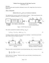
Fig. 3. A linearized one-machine, infinite bus model<br />
Table 1. Constants of one-machine, infinite-bus model<br />
Generator<br />
Constants<br />
Exciter Constants<br />
Line Constants<br />
Initial Constants<br />
M= 9.26, D= 0, T,,'= 7.76<br />
X ~ Z 0.973, ~d'= 0.19, xq= 0.55<br />
K,= 50, TA= 0.05<br />
R1=-0.051, XI= 1.49, R2=-0.102<br />
X2 = 2.99, G = 0.249, B= 0.262<br />
P,,= 1.0, Qeo= 0.015, V,,= 1.05<br />
It is noted the system has a non-minimum phase zero and a<br />
zero at the origin. The FARMA FLC can be interpreted as a<br />
kind of inverse model trainer by (2). However, it is well<br />
known that the non-minimum phase zero plant can't be<br />
controlled by pole-zero cancellation because of the internal<br />
instability. In other words, the control value U, can diverge<br />
in order to maintain the Am to zero. Moreover, the system has<br />
a zero at the origin, which means U, is not unique in the'<br />
steady state. It is recommended the steady state control value,<br />
U,, of PSS be zero since it is a supplementary control.<br />
Therefore, a modification of the FARMA FLC is necessary to<br />
prevent the divergence and non-zero steady state value of U,.<br />
To overcome these problems, we directly limit the control<br />
value according to the output error as follows:<br />
SOPSS will be learning the system from the input-output data<br />
as it stabilizes the unknown system. Consequently, the<br />
SOPSS will be adapive from system to system, from one<br />
operating condition to another operating condition. For<br />
illustration purpose, the system considered in this paper is a<br />
synchronous generator connected to an infinite bus through<br />
two transmission lines, Fig. 2. During low frequency<br />
oscillations, the linearized model can be drawn as Fig. 3 [2].<br />
For the calculation of constants - K ~ the , initial currents,<br />
voltages and torque angle of the system in a steady state must<br />
be known. These initial values are found from a load flow<br />
study. Since the real system is nonlinear, the parameters<br />
K~ - p(, are changed with the load and the system conditions.<br />
However, for demonstration purpose, we select few operating<br />
conditions for the linearized model.<br />
Table 1 shows the values of system parameters. The<br />
negative RI and R2 stem from deriving the one-machine,<br />
infinite bus model for a multimachine system by<br />
equivalencing smaller generators by equivalent impedances<br />
with negative resistances. Without supplementary excitation,<br />
the system is unstable and has a non-minimum phase zero<br />
and a zero at the origin.<br />
The supplementary control U, is applied through the<br />
T,, and K~ blocks in Fig. 3 to obtain the extra damping<br />
AT, in Fig. 3. Since it is a linearized model, a conventional<br />
PSS as a phase lead compensation is included by the<br />
superposition principle. If Am is the control input, the control<br />
including the reset block becomes as follows [2]:<br />
where, uyk) : modified control value,<br />
K : feedback constant,<br />
u(k) : control value of FARMA FLC.<br />
In (12), yref is the reference output, i. e., zero for speed<br />
deviation in this paper. Then, the modified control value is<br />
decreased with the output error (yref - y(k)). Moreover, in<br />
steady state it always becomes zero.<br />
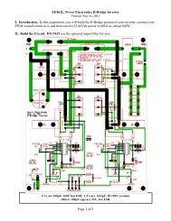
Fig. 4 shows the modification of the FARMA FLC for<br />
PSS. The plant input U' is U, and the output y is Am as in the<br />
conventional method. The plant output and input values,<br />
y(k + 1). y(k), . .') y(k - 3), u'(k), . . .,u'(k - 3) are used to form the<br />
FARMA rule. The target ratio constant a and feedback<br />
constant K are chosen by off-line. The sampling time is 0.02<br />
sec. The proposed FARMA PSS doesn't assume a plant<br />
model, instead it learns the behavior of the plant by inputoutput<br />
history. Therefore, it can cope with unexpected load<br />
conditions and faults.<br />
I<br />
I 1<br />
Fig. 4. The <strong>Self</strong>-organizing <strong>Power</strong> <strong>System</strong> <strong>Stabilizer</strong><br />
i<br />
I