

Industrial Grade Modems Hidex HXIIxxTM User Manual Description
Industrial Grade Modems Hidex HXIIxxTM User Manual Description
Industrial Grade Modems Hidex HXIIxxTM User Manual Description

You also want an ePaper? Increase the reach of your titles
YUMPU automatically turns print PDFs into web optimized ePapers that Google loves.
<strong>Industrial</strong> <strong>Grade</strong> <strong>Modems</strong> <strong>Hidex</strong> <strong>HXIIxxTM</strong> <strong>User</strong> <strong>Manual</strong><br />
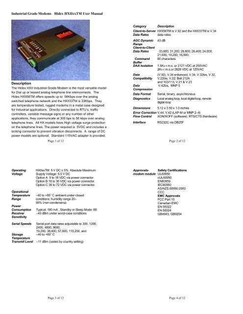
<strong>Description</strong><br />
The <strong>Hidex</strong> HXII <strong>Industrial</strong> <strong>Grade</strong> Modem is the most versatile model<br />
for Dial up or leased analog telephone line interconnects. The<br />
<strong>Hidex</strong> HXII56TM offers speeds up to 56Kbps over the analog<br />
switched telephone network and the HXII33TM is 33Kbps. They<br />
are temperature tested, rugged modems in a metal case designed<br />
for <strong>Industrial</strong> applications. Directly connected to RTU’s, traffic<br />
controllers, variable message signs or any number of other<br />
applications, they communicate at 300 bps to 56 kbps over analog<br />
telephone lines. All HX models have High voltage surge protection<br />
on the telephone lines. The power required is 5VDC and includes a<br />
locking connector to prevent vibration disconnects. A range of DC<br />
power models are optional. Standard 115VAC adapter is provided.<br />
Page 1 of 12<br />
Category<br />
Client-to-Server<br />
Data Rates<br />
<strong>Description</strong><br />
HXII56TM is V.92 and the HXII33TM is V.34<br />
data rates<br />
AGC Dynamic 43 dB<br />
Range<br />
Client-to-Client<br />
Data Rates 33,600; 31,200; 28,800; 26,400; 24,000;<br />
21,600; 19,200; 16,800;<br />
Command 60 characters<br />
Buffer<br />
DAA Isolation 1.5Kv r.m.s. or 2121 VDC at 250VAC<br />
2Kv r.m.s.or 2828 VDC at 125VAC<br />
Data<br />
Compatibility<br />
Data<br />
Compression<br />
Data Format<br />
Diagnostics<br />
(V.92), V.34 enhanced, V.34, V.32bis, V.32,<br />
V.22bis, V.22; Bell 212A<br />
and 103/113, V.21 & V.23<br />
V.42bis, MNP 5<br />
Serial, binary, asynchronous<br />
Local analog loop, local digital loop, remote<br />
digital loop<br />
Dimensions 5.12 x 3.50 x 1.0 inches<br />
Error Correction V.44, V.42 (LAP-M or MNP 2–4)<br />
Flow Control XON/XOFF (software), RTS/CTS (hardware)<br />
Interface RS232C via DB25F<br />
Page 2 of 12<br />
Operating<br />
Voltage<br />
Operational<br />
Temperature<br />
Range<br />
<strong>HXIIxxTM</strong> 5 V DC ± 5% Absolute Maximum<br />
Supply Voltage: 5.5 V DC<br />
Option A 9 to 18 VDC via power connector.<br />
Option B 18 to 36 VDC via power connector.<br />
Option C 36 to 72 VDC via power connector.<br />
–40 to +85° C ambient under closed<br />
conditions; humidity range 20–<br />
90% (non-condensing)<br />
Power<br />
Consumption Typical: 180 mA , Standby or Sleep Mode: 88<br />
Receiver –43 dBm under worst-case conditions<br />
Sensitivity<br />
Approvalsmodem<br />
module<br />
Safety Certifications<br />
UL60950<br />
cUL60950<br />
EN60950<br />
IEC60950<br />
AS/NZS 60950:2000<br />
CCC<br />
EMC Approvals<br />
FCC Part 15<br />
Canadian EMC<br />
EN 55022<br />
EN 55024<br />
GB4943, GB9254<br />
Serial Speeds Serial port data rates adjustable to 300, 1200,<br />
2400, 4800, 9600,<br />
19,200, 38,400, 57,600, 115,200, and<br />
Storage –40 to +85° C<br />
Temperature<br />
Transmit Level –11 dBm (varies by country setting)<br />
Page 3 of 12<br />
Page 4 of 12
Intelligent<br />
Features<br />
Fully AT command compatible<br />
Leased-line operation (HXII56TM Only)<br />
Sleep mode<br />
Autodial, redial<br />
Pulse or tone dial<br />
Dial pauses<br />
Auto answer<br />
Adaptive line probing<br />
Automatic symbol and carrier frequency during<br />
start-up, retrain,<br />
and rate renegotiations<br />
DTMF detection<br />
Callback security<br />
Distinctive ring<br />
Voice record and playback<br />
Call status display, auto-parity and data rate<br />
selections<br />
Keyboard-controlled modem options<br />
On-screen displays for modem option<br />
parameters<br />
remote configuration<br />
DTR dialing<br />
phone number storage<br />
flash memory for firmware updates<br />
NVRAM storage for user-defined parameters<br />
IC-CS03<br />
ETSI TS 103 021-1,2,3 v.1.1.2 2003-09 (originally CTR21)<br />
ESD<br />
(See Complete <strong>HXIIxxTM</strong> AT Commands for setting country codes)<br />
External Power Sources<br />
The native power for model <strong>HXIIxxTM</strong> is 5VDC to the power<br />
connector or via DB25 connector. The power options A, B & C are<br />
internal and changes the external power to be supplied via the 2 pin<br />
green locking connector. If no option is selected the 115VAC<br />
external supply is provided.<br />
• Power option A is 9 to 18 VDC.<br />
• Power option B is 18 to 36 VDC.<br />
• Power option C is 36 to 72 VDC.<br />
Standard 115VAC adapter<br />
Compliance to Global Telephone Standards<br />
<strong>Hidex</strong> II modems have passed the following homologation:<br />
FCC Part 68<br />
FCC Part 15<br />
Page 5 of 12<br />
Power Connections<br />
There are two optional methods of supplying power to the modem.<br />
Use the locking 2 pin power connector or via the RS232 cable. A<br />
slide switch on the side of the case selects which is used.<br />
Page 6 of 12<br />
Included with each modem is the mating connector for the input<br />
power. Connect the external 5 VDC power source to the supplied<br />
connector with attention to the +/- polarity of the voltage source.<br />
CAUTION: NOTE THE POLARITY ON THE CONNECTOR LABEL.<br />
Use the GREEN case cover screw to connect a safety ground wire if desired<br />
Data Interface<br />
Data is interfaced via a DB25 female connector.<br />
Pin 10 plus 5VDC and pin 7 ground<br />
Alternate power can be connected via the DB25 connector pin # 10<br />
for +5VDC and pin # 1 or 7 for ground. To enable this option, move<br />
the switch away from the power connector.<br />
Safety Ground Connection<br />
Page 7 of 12<br />
Pin 1 GRD Signal Ground<br />
Pin 2 TXD Transmit Data<br />
Pin 3 RXD Receive Data<br />
Pin 4 RTS Request to Send<br />
Pin 5 CTS Clear to Send<br />
Pin 6 DSR Data Set Ready<br />
Pin 7 SG<br />
Signal Ground<br />
Pin 8 DCD Carrier Detect<br />
Pin 10<br />
(Alternate power input +5VDC) use switch<br />
Pin 20 DTR Data Terminal Ready<br />
Pin 22 RI Ring Indicate<br />
LED Indicators<br />
DCD Data Carrier Detect<br />
RTS Request To Send<br />
CTS Clear To Send<br />
Page 8 of 12
TXD<br />
RXD<br />
RI<br />
PWR<br />
Transmit Data<br />
Receive Data<br />
Ring Indicate<br />
Power indicator (green)<br />
Hardware Setup:<br />
Setup Procedure:<br />
1. Use the RS-232 cable to connect the DB25 connector<br />
(J1) on the modem to a PC serial port<br />
(Typically COM1).<br />
2. Connect the RJ11 connector to a phone line.<br />
3. Connect external power +5VDC to the power jack via 2<br />
pin green connector or via alternate DB25 pins 10 & 7.<br />
Hyper Terminal setup:<br />
The modem can be tested as a standard serial data modem by<br />
connecting it to a personal computer or other data terminal<br />
equipment (DTE). Any standard terminal program such as<br />
HyperTerminal or ProComm running on a PC will communicate with<br />
the modem.<br />
AT Commands<br />
AT refers to the command prefix (attention sequence) that precedes<br />
each command to the modem. With the exception of A/ all<br />
commands must be preceded by AT and end with a carriage return<br />
. Some useful AT commands commonly used are:<br />
The A/ command instructs the modem to repeat the last command<br />
line. A command line termination character is not required for the<br />
execution of this command (that is, the command is executed as<br />
soon as the slash is typed).<br />
Page 9 of 12<br />
AT Command Summary<br />
Organization of AT Commands on the following pages: 1st, by the<br />
initial command character (&, +, %) 2nd, alphabetized by the<br />
second command character (Except for listing of AT).<br />
Command <strong>Description</strong><br />
AT Attention Code<br />
A Answer<br />
A/ Repeat Last Command<br />
Bn Communication Standard Setting<br />
Ds Dial<br />
DS=y Dial Stored Telephone Number<br />
En Echo Command Mode Characters<br />
Fn Echo Online Data Characters<br />
Hn Hook Control<br />
Command <strong>Description</strong> (con’t)<br />
In Information Request<br />
Mn Monitor Speaker Mode<br />
Nn Modulation Handshake<br />
On Return Online to Data Mode<br />
P Pulse Dialing<br />
Qn Result Codes Enable/Disable<br />
Sr=n Set Register Value<br />
Sr Read Register Value<br />
T Tone Dialing<br />
Vn Result Code Format<br />
Wn Result Code Options<br />
Xn Result Code Selection<br />
Zn Modem Reset<br />
&Cn Data Carrier Detect (DCD) Control<br />
&Dn Data Terminal Ready (DTR) Control<br />
&En XON/XOFF Pass-Through<br />
&Fn Load Factory Settings<br />
Page 10 of 12<br />
&Gn V.22bis Guard Tone Control<br />
&Kn Flow Control Selection<br />
&Ln Leased Line Operation<br />
&Pn Pulse Dial Make-to-Break Ratio Selection<br />
&Qn Asynchronous Communications Mode<br />
&Sn Data Set Ready (DSR) Control<br />
&Tn Loopback Test (V.54 Test) Commands<br />
&V Display Current Settings<br />
&Wn Store Current Configuration<br />
&Zy=x Store Dialing Command<br />
\An Select Maximum MNP Block Size<br />
\Bn Transmit Break<br />
\Kn Break Control<br />
\Nn Error Correction Mode Selection<br />
\Qn Flow Control Selection<br />
Command <strong>Description</strong> (con’t)<br />
\Tn Inactivity Timer<br />
\Vn Protocol Result Code<br />
-Cn Data Calling Tone<br />
%A Adaptive Answer Result Code Enable<br />
%B View Numbers in Blacklist<br />
%Cn Data Compression Control<br />
%DCn AT Command Control<br />
%En Fallback and Fall Forward Control<br />
%Hn Direct Connect Enable<br />
%Rn Cisco Configuration<br />
%Sn Command Speed Response<br />
$EBn Asynchronous Word Length<br />
$Dn DTR Dialing<br />
$MBn Online BPS Speed<br />
$SBn Serial Port Baud Rate<br />
#CBAn Callback Attempts<br />
#CBDn Callback Delay<br />
# CBF Callback Failed Attempts Display<br />
Page 11 of 12<br />
# CBFR Callback Failed Attempts Reset<br />
# CBIn Local Callback Inactivity Timer<br />
# CBNy=n Store Callback Password<br />
# CBPn Callback Parity<br />
# CBRy Callback Security Reset<br />
# CBSn Callback Enable/Disable<br />
#Pn Set 11-bit Parity<br />
#Sx Enter Setup Password<br />
#S=x Store Setup Password<br />
+VDR=x, y Distinctive Ring Report<br />
+++AT Escape Sequence<br />
%%%ATMTSMODEM Remote Configuration Escape<br />
Sequence<br />
Page 12 of 12


