ET15 - Andrews Sykes
ET15 - Andrews Sykes
ET15 - Andrews Sykes

Create successful ePaper yourself
Turn your PDF publications into a flip-book with our unique Google optimized e-Paper software.
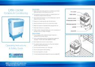
<strong>ET15</strong><br />
Portable Air Conditioning<br />
Operating Instructions<br />
& Safety Guide<br />
General Safety<br />
Keep children and animals away from air conditioning units.<br />
Never leave them alone in a room where the units in use.<br />
This equipment should only be used by a competent person who has read<br />
and understood these instructions.<br />
Never operate this equipment if you are ill, feeling tired or under the influence<br />
of alcohol or drugs.<br />
Keep the Air Conditioning vents clear of all obstructions.<br />
Never put anything on top of the unit or block the air outlets.<br />
Make sure equipment is switched off and unplugged after use<br />
Never leave switched on or unattended.<br />
Do not use the unit where sunlight is shining directly onto it.<br />
Check condition of equipment before use. If unit is showing signs of damage<br />
contact your supplier immediately.<br />
Electrical Safety<br />
This unit requires a 230 volt electrical supply. It plugs into a standard bs1363<br />
domestic socket.<br />
Always inspect plugs and leads for damage before plugging into the supply -<br />
DO NOT USE IF ANY DAMAGE IS FOUND<br />
Ensure cables are run as not to cause a hazard.<br />
If an extension lead is used, ensure it is of the correct standard , and fully<br />
uncoiled when being used.<br />
Do not lay electrical cables in wet / damp areas.<br />
Do not move equipment whilst operating.<br />
Do not pull equipment by its cable.<br />
It is recommended that electrical equipment is used via a suitable RCD.<br />
WARNING!<br />
This unit MUST be transported and operated in the upright position at all times<br />
Electrical Supply<br />
As standard this unit requires a 13 amp fused electrical supply rated at 230v 1ph 50hz.<br />
The unit will operate from a standard 13A wall socket. The size of any extension<br />
cable that may be 2-5mm2 minimum up to a maximum length of 10 metres. For<br />
longer lengths 4mm2 cable must be used. If the cable is on a ‘cable drum’ then<br />
ensure that it is completely unwound; serious complications will occur otherwise.<br />
Air Cooled Units<br />
The system comprises, a room unit fitted with either a fixed or flexible ducting system<br />
as specified by the customer. Condensate is collected, either in the units internal tank<br />
and emptied by the user or pumped using an optional condensate disposal unit (fig. 1).<br />
Air Flow<br />
The angled air outlets at the top of the room unit are fitted with air grilles that allow the<br />
angle of air outlet to be adjusted vertically and horizontally and, in conjunction with the<br />
fan speed control switch, the air velocity and direction can be carefully set up to obtain<br />
maximum coverage of the area being cooled without causing drafts. Care should be<br />
taken to avoid outlet air being obstructed as this will cause the air to ‘eddy’ around the<br />
unit resulting in recirculation and short/inaccurate cycling of the machine. Ideally, cold<br />
air should be directed to create a ‘blanket’ all across the ceiling area allowing natural<br />
convection to drop the air over the whole area at very low velocity. An alternative top<br />
panel with twin 7” ducts is available.<br />
Siting of ET 15<br />
Ideally, the room unit should be positioned equidistant along he shortest wall in the<br />
room blowing down the length of the room. Of there is more than one unit in the<br />
same area, then they would normally be positioned side by side, and equidistant<br />
along the long wall, all pointing in the same direction. Sometimes it may be<br />
necessary to position units around the perimeter of an area but, in this case, great<br />
care should be taken t avoid one unit blowing cold air straight into another which<br />
will adversely affect the machine operation. Good and correct air flow is, perhaps,<br />
the single most important aspect of satisfactory applying portable air conditioners.<br />
If in doubt seek the advice of your supplier.<br />
Exhaust Tubes Air Cooled Unit<br />
The exhaust tube(s) must carry the air to an area external to that being cooled,<br />
preferably in the outside atmosphere (fig. 1).<br />
NOTE: most domestic proprietory extension cables are 1.5mm². This is not sufficient.<br />
Fitting the hot air exhaust<br />
Keep the exhaust pipes as straight as<br />
possible. Do not allow to sag.<br />
Click www.andrews-sykes.com<br />
or Call Us Free 0800 211 611
Operating Instructions - <strong>ET15</strong><br />
Fitting the hot air exhaust<br />
Fig.2<br />
Operation Instructions<br />
The control panel on the room unit is illustrated above<br />
Revolve thermostat knob fully CLOCKWISE to the number ‘8’ position<br />
determined by the user. However, you should never allow more than two months<br />
to elapse between cleaning. The probable life of the filter will be about one year<br />
and spares are available from the supplier of the unit itself. Failure to have filter fitted<br />
during operation will cause serious damage.<br />
Plug in the room unit mains cable, and switch on the electricity, red mains<br />
light will illuminate.<br />
Select ‘Fan Only’ with the mode switch. The fan will start.<br />
Select ‘Fan Speed’ with the fan speed switch, high or low depending on air<br />
velocity required.<br />
Select ‘Cooling’ with the mode switch, and revolve the thermostat knob fully<br />
ANTI-CLOCKWISE to he number ‘1’ position. After a delay of 10 mins the<br />
green ‘Cooling’ light will illuminate and the machine will proceed to cool the air.<br />
Monitor the room temperature and when it has reduced to the desired level, very<br />
slowly revolve the thermostat knob back, clockwise until the green ‘Cooling’<br />
light goes out. The room unit will now control the room temperature cooling<br />
automatically at this setting.<br />
Routine Maintenance<br />
The air filter must be kept clean, never allow to become choked with dust or dirt. If<br />
allowed to do so, the performance of the unit will become impaired, resulting in loss of<br />
air flow, freezing up the evaporator coil and possible component damage.<br />
Accessing the Filter<br />
On machines fitted with a hinged lower panel, open panel. The filter is located on<br />
front of the evaporator. A second filter is fitted to the rear panel on all air cooled<br />
machines (fig. 5 & 6).<br />
The filter can be washed in warm, soapy water, rinsed and shaken dry before<br />
replacement. Frequency of cleaning depends upon application and can only be<br />
Problem Likely Cause Solution<br />
No cooling Amber ‘ATTENTION’ light<br />
illuminated. High level<br />
condensate trip.<br />
Condensate pump not reducing water level.<br />
Kink in condensate tube between room unit<br />
and external heat exchanger<br />
Leak inside room unit. Pump filter inside<br />
room unit blocked. Condensate tube frozen.<br />
No cooling Amber ‘ATTENTION’ light ensure bottle fitted correctly.<br />
illuminated. Bottle fitted<br />
switch trip.<br />
No cooling Amber ‘CONTAINER FULL’<br />
light illuminated. High level<br />
condensate trip.<br />
On machines without a removable<br />
bottle, as above. On machines with a<br />
bottle, remove container and replace<br />
correctly.<br />
To empty the condensate bottle:<br />
Unscrew the 2 x thumb screws on the<br />
front panel (fig. 2).<br />
The front cover will hinge forward, giving<br />
access to the container (fig. 3).<br />
Empty the container, and carefully<br />
replace (fig 4).<br />
Ensure the drain pipe is fitted into the<br />
container.<br />
Fig.3<br />
Fig.5<br />
Fig.4<br />
Fig.6<br />
Fig. 5 - The filter is located on the rear of the unit, ensure it is kept clean.<br />
Fig. 6 - And in the top of the hinged section, in front of the evaporator.<br />
Fig.1<br />
Click www.andrews-sykes.com or Call Us Free 0800 211 611