SA-12 WARRANTY ROTATING AND REPLACING THE OS2 - Stanton
SA-12 WARRANTY ROTATING AND REPLACING THE OS2 - Stanton
SA-12 WARRANTY ROTATING AND REPLACING THE OS2 - Stanton

Create successful ePaper yourself
Turn your PDF publications into a flip-book with our unique Google optimized e-Paper software.
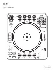
<strong>ROTATING</strong> <strong>AND</strong> <strong>REPLACING</strong> <strong>THE</strong> <strong>OS2</strong><br />
<strong>ROTATING</strong> INSTRUCTIONS<br />
1 . Remove the face plate.<br />
2. Remove the 2 outer screws from the<br />
round <strong>OS2</strong> plate (removing the 2 inner<br />
screws will detach the fader from the<br />
plate)<br />
3. Rotate the plate to the desired position<br />
and tighten the screws back into<br />
the top and bottom holes.<br />
<strong>WARRANTY</strong><br />
This unit has been designed and manufactured<br />
using quality components.<br />
Therefore, it is warranted to be free<br />
from defects in materials (limited as<br />
specified below), and workmanship for<br />
a period of twelve (<strong>12</strong>) months from the<br />
original purchase date. During this<br />
period, all service and parts necessary<br />
to repair a defect will be free of charge.<br />
This limited warranty applies to<br />
mechanical parts which are subject to<br />
wear and tear as specified: Faders,<br />
specified durability: 15,000 cycles;<br />
Rotary potentiometers, specified durability:<br />
10,000 cycles; Switches, speci -<br />
fied durability: 10,000 cycles.<br />
© 2001, <strong>Stanton</strong> Magnetics, LLC<br />
<strong>REPLACING</strong> INSTRUCTIONS<br />
1. Remove the the face plate.<br />
2. Remove the 2 outer screws from the<br />
round plate (removing the 2 inner<br />
screws will detach the fader from the<br />
plate)<br />
3. Remove the <strong>OS2</strong> assembly and disconnect<br />
the cable coming from the<br />
mixer.<br />
4. Set the replacement fader assembly<br />
in the desired position and place the<br />
screws back in the top and bottom<br />
holes.<br />
Consequently, the parts listed above<br />
are warranted to be free from defects in<br />
materials and workmanship for a period<br />
of thirty days (30) days from the<br />
original purchase date.<br />
For the warranty to be valid, please<br />
complete the warranty registration card<br />
attached or fill out the online registration<br />
at www.stantonmagnetics.com<br />
Mail completed warranty cards to:<br />
<strong>Stanton</strong> Magnetics, Inc, 3000 SW 42st<br />
• Hollywood, FL 333<strong>12</strong><br />
<strong>SA</strong>-<strong>12</strong><br />
DJ CRAZE SIGNATURE MIXER<br />
OWNER’S MANUAL<br />
STANTON MAGNETICS, INC<br />
info@stantonmagnetics.com • (954) 689-8833<br />
www.stantonmagnetics.com
Thank you for making <strong>Stanton</strong> your first choice in professional DJ mixers.<br />
This innovative family of mixers has been developed with input from the<br />
professional DJ community, bringing to the marketplace a previously<br />
unavailable, affordable combination of user-friendly, functional design,<br />
rugged construction, and professional quality features.<br />
<strong>Stanton</strong> and your authorized <strong>Stanton</strong> dealer are dedicated to your complete<br />
satisfaction by offering benchmark service and support throughout the long<br />
life of your <strong>Stanton</strong> product.<br />
Again, we appreciate your patronage, and look forward to many years of<br />
making music together.<br />
PLEASE READ CAREFULLY BEFORE USE<br />
FAILURE TO FOLLOW <strong>THE</strong> INSTRUCTIONS PRINTED BELOW MAY VOID <strong>WARRANTY</strong><br />
• Follow all security advice printed on your mixer<br />
• When removing the unit's AC plug from the power source, grasp and pull<br />
the plug, NEVER the cord itself!<br />
• Avoid placing your mixer near heat sources, such as power amplifiers.<br />
• When in use, place your mixer on a stable surface, away from vibration.<br />
Always use care when carrying your mixer. Impact, or heavy vibration may<br />
compromise the unit's mechanical integrity. The manufacturer is not<br />
responsible for damage resulting from an impact, or misuse.<br />
• When in use, place your mixer away from sources of hum or noise, such as<br />
transformers, or electric motors.<br />
• To prevent overheating, always provide your mixer with adequate<br />
ventilation air space.<br />
• Avoid stepping on your mixer's AC cord. Repeated compression of the cord<br />
may lead to electrical shorting.<br />
• To avoid damage due to AC voltage peaks, always disconnect your mixer<br />
from the power source during electrical storms. If possible connect mixer to<br />
a surge protector.<br />
• Your mixer contains no user-serviceable parts. The manufacturer is not<br />
responsible for any damage or personal injury resulting from unauthorized<br />
user-servicing or modifications. In addition, the warranty will be void if any<br />
unauthorized service by the user is detected. Always return your mixer to<br />
an authorized <strong>Stanton</strong> dealer for servicing.<br />
TECHNICAL SPECIFICATIONS<br />
Line inputs: 2 (RCA), -10dBV @
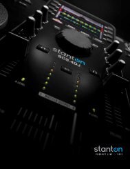
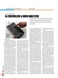
FADER CLEANING <strong>AND</strong> REPLACEMENT<br />
remove the slider assembly (C), ensuring that the wiper contacts (D) are<br />
not damaged as this will affect the operation of the fader. Clean the slider<br />
assembly by gently wiping the wiper contacts and slider bearings (E)<br />
using a tissue or cotton bud. If slider bearing are exessively worn, as indicated<br />
by exessive slider rocking then contact <strong>Stanton</strong> for replacement.<br />
3. Remove the single upper screw on the<br />
opposite end block to remove the guide rail.<br />
Clean the guide rail (F) with a tissue or<br />
cloth, removing all traces of dirt and conta -<br />
mination.<br />
4. Remove the fader track (G) by slowly with -<br />
drawing from the unit. Place fader track on<br />
desk or working surface with black contacts facing upwards.<br />
If necessary, the track can be washed in warm water, wiped<br />
gently then dried thoroughly using a dry cloth. Use a lint free<br />
cloth or swab to wipe the tracks and check for marks along<br />
the track. (Note: Lint free cloth should be used to avoid<br />
dust/fibres being deposited on the track). If the track appears<br />
exessively worn, or if cleaning does not improve operation,<br />
replacement may be necessary.<br />
5. Examine the center channel of the fader body and if dirty, clean using cotton<br />
buds.<br />
6. Re-assemble and lubricate the fader as follows:<br />
6.1) Secure the end block and guide rail onto the fader body.<br />
6.2) Insert track into the fader body.<br />
6.3) Insert slider assembly onto guide rail and into the fader body. Move<br />
slider from end to end to disperse the oil evenly. Carefully wipe away any<br />
excess oil using a tissue or cloth.<br />
6.4) Lubricate the guide rail by placing one drop of silicon liquid oil onto<br />
the guide rail (F).<br />
6.5) Insert dust cover.<br />
6.6) Insert fader track back into fader body with wires coming out open<br />
end of fader body.<br />
6.7) Secure the remaining end block ensuring that the track wires (I) are<br />
not pinched between the endblock and fader casing.<br />
7. Once assembled, move the slider from end to end to ensure operation is<br />
smooth.<br />
8. Attach fader to fader plate. (NOTE: As noted earlier if you do not want to<br />
change positioning of fader, keep the 2 fader plate screws loose and shift<br />
the fader until it is aligned with the marks you created in step 1, then tighten<br />
fader plate screws.)<br />
G<br />
I<br />
<strong>SA</strong>-<strong>12</strong> FUNCTIONS & FEATURES<br />
It’s only the 3x champion, DJ Craze signature mixer! This battle mixer has the all<br />
the quality of a club mixer and meets all the requirements of today's Turntablist.<br />
After years in the making the ultimate Scratch DJ mixer is here and ready for battle.<br />
Removable Effects Module<br />
The MOD1 removable effects module<br />
includes 3 effects: Pitch Shifter,<br />
Flanger, and Delay. All effects have<br />
adjustable parameters and levels, can<br />
be assigned (turned on / off) to all<br />
channels or master output, and can be<br />
turned ON/OFF using any standard<br />
footswitch via the remote Start output.<br />
<strong>OS2</strong> Optical Scratch Switch<br />
These ultra quiet, non friction<br />
phono/line switches allow you to transform<br />
without the clicking or static noise<br />
found in other line switches. Now<br />
including a special feature that locks<br />
the last position of the switch.<br />
FEATURES:<br />
• Focus Fader V2 Digital Optical<br />
Crossfader (Patent Pending) with<br />
curve adjustment and reverse switch.<br />
• <strong>OS2</strong> (Patent Pending) Optical Scratch<br />
switches with lock feature<br />
• Removable effects module (Patent<br />
Pending). <strong>SA</strong>-<strong>12</strong> includes MOD1:<br />
Pitch Shifter, Flanger, and Delay; with<br />
Parameter and Mix controls.<br />
• Effects fully assignable<br />
• Foot pedal output to control effects.<br />
• 3 position cue select (Patent Pending)<br />
Pre CF Cue / Post CF Cue / Master.<br />
• 2 line, 2 phono, and 1 mic/line (switchable)<br />
inputs.<br />
• Program Reverse.<br />
3 position Cue Select<br />
This switch allows you to set your cue<br />
source to PFL/Pre -crossfader,<br />
PFL/Post-crossfader, or Master. This<br />
unique PFL/Post-crossfader features<br />
allows you to practice and cue your<br />
scratches using the crossfader<br />
(instead of the cue pan fader) during a<br />
live show.<br />
Mic/Line Channel<br />
The <strong>SA</strong>-<strong>12</strong>’s Mic/Line channel features<br />
an input selector switch activating a 3rd<br />
line input (RCA) or a standard microphone<br />
input, both controlled by a 2band<br />
EQ with gain adjustment. This<br />
can also be used as a "session in" with<br />
volume control for linking additional<br />
mixers.<br />
• 3 band EQ with complete kill, Gain,<br />
and Pan control per channel.<br />
• Program Faders reverse switches &<br />
curve adjustments.<br />
• Headphone mute.<br />
• Cue Pan Fader<br />
• Dual headphone inputs (1/4 and 1/8<br />
mini-jack).<br />
• TRS balanced Master output.<br />
• Mono-Stereo Switch.<br />
• Output Trim control.<br />
• Quiet-Start feature to avoid pops /<br />
noise when mixer is powered on.
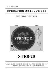
DESCRIPTION OF FUNCTIONS<br />
PostScript Picture<br />
<strong>SA</strong>-<strong>12</strong>_callouts.eps<br />
FADER CLEANING <strong>AND</strong> REPLACEMENT<br />
After constant scratch use the <strong>SA</strong>-<strong>12</strong> faders may need to be cleaned and lubri -<br />
cated from time to time. This will ensure long life and keep a smooth feeling<br />
throughout the fader's lifetime. Follow the instructions below to lubricate and<br />
clean your faders:<br />
Removing a fader:<br />
1. Make sure mixer is powered off and power supply is<br />
disconnected from back of mixer.<br />
2. To remove the lower faceplate, take off the 3 fader<br />
knobs and then remove the 4 screws located on<br />
the sides of the mixer (2 on each side). See Figure<br />
1. Lift up on the faceplate and it will slide off.<br />
3. Remove the fader to be cleaned or replaced by<br />
unscrewing the 2 outer screws on the fader plate<br />
(removing the 2 inner screws will detach the fader<br />
from the fader plate). See Figure 2.<br />
4. Disconnect the fader from mixer by removing the 4pin<br />
connector on the bottom of the fader.<br />
Replacing a fader:<br />
1. Once original fader has been removed, simply plug<br />
the 4-pin connector into the new fader. NOTE: The<br />
<strong>SA</strong>-<strong>12</strong> comes with 2 connectors, one for P+G<br />
faders and one for Focus Faders. Make sure you<br />
plug in the correct fader with the correct connector.<br />
See Figure 3.<br />
2. Set selector switch to position of fader you are using<br />
(P+G or Focus Fader). See Figure 3.<br />
3. Place fader back in mixer and replace 2 outer<br />
screws to secure fader.<br />
Cleaning a Penny & Giles fader:<br />
1. Remove 2 mounting scews from faderplate. (NOTE:<br />
The P&G fader is designed with floating mounting<br />
threads for precise mechanical centralising of the<br />
fader. If you desire to keep your fader`s current<br />
mounting position we suggest that you make 2<br />
marks on both ends of the fader on the fader plate<br />
to indicate the P&G fader posi -<br />
tion.) See Figure 4.<br />
2. Once fader is removed from unit,<br />
remove the two screws (A) from<br />
the end of the fader body where<br />
the wires exit the fader casing. Pull<br />
away the end block. Withdraw the<br />
dust cover (B). Taking great care,<br />
A<br />
B<br />
G<br />
F<br />
C<br />
Figure 3<br />
D<br />
E
FOCUS FADER V2<br />
Improving on the original and world's first optical fader design that brought the<br />
industry and art to a new plateau, the Focus Fader V2 is truly curve adjustable to<br />
accommodate to any style of DJ artist. Created to meet the requirements of<br />
today’s higher standards , if your style requires a smooth fade for long mixes or a<br />
razor sharp cut-off for precise scratching, V2 is the answer.<br />
Just as it's predecessor started a movement in contactless fader designs, the<br />
Focus Fader V2 Digital Optical Fader will continue to push the envelope. No more<br />
bleeding, no more static, no more wasted time, just hours of practice enjoyment<br />
and flawless performance.<br />
The Focus Fader V2 is highly advanced and opens many doors for innovations in<br />
DJ equipment technology. Fitted with an array of optic sensors and microproces -<br />
sor controlled to eliminate the need for contacts or graphite material. V2 is as pure<br />
as the sun rays. It will outlast any standard graphite or conductive plastic fader on<br />
the market. This is why the it has a limited lifetime warranty (see warranty information<br />
section).<br />
The Focus Fader V2 is history in the making.<br />
OPTICAL SCRATCH SWITCH (<strong>OS2</strong>)<br />
Since the early days of DJing and Scratching the Phono/Line Switch had been an<br />
integral part of an artist’s performance. In recent years the new techniques in<br />
scratching have evolved to a point that surpassed the typical contact switch which<br />
is too noisy to use in a performance. This led to the decline of its use. In any art<br />
form the goal should be to move forward, the slow decline of the phono/line switch<br />
use was a step backwards. Introducing the <strong>OS2</strong>.<br />
Just as the introduction of the Focus Fader V1 has changed the face of the DJ<br />
world for the good of all, so will the <strong>OS2</strong>. The Benefits are the same as other opti -<br />
cal devices, such as the Focus Fader.: 1. No more static, 2. No more bleeding, 3.<br />
Lots of scratching fun.<br />
One Step Further: In addition to the sound benefits the <strong>OS2</strong> also represents a<br />
<strong>Stanton</strong> innovation in it's mechanical properties as well. It is the 1st phono/line<br />
switch which uses a fader as the user interface. This will allow the same<br />
hand/wrist movement to be executed when using the crossfader and <strong>OS2</strong> which<br />
in turn translates into efficiency in Scratching performance.<br />
The flat handle and soft slide action of the <strong>OS2</strong> makes it easy to perform any exist -<br />
ing techniques including the Crab Scratch. The small travel and slide motion will<br />
be a positive tool in conditioning the hand/wrist movements to be more minute and<br />
precise. In conclusion the <strong>OS2</strong> is another step forward in the Evolution of the DJ<br />
Culture and of course as always Scratching.<br />
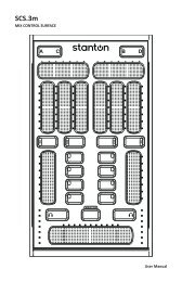
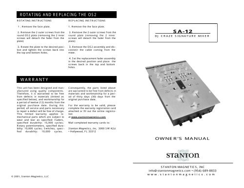
TOP PANEL<br />
1. Mic/Line 3 level control: Controls<br />
the output level of the microphone/<br />
Line channel.<br />
2. Gain: Controls the gain of each input<br />
channel.<br />
3. Mic/ Line 3 EQ: Individual controls<br />
for low and high frequency equaliza -<br />
tion with (+/-10 dB)<br />
4. EQ: Individual controls for low fre -<br />
quency, midrange, and high frequency<br />
equalization with (+9dB/Kill) Note: Any<br />
changes made to EQ settings will<br />
change the overall output level.<br />
5. FX ON/OFF: These backlit buttons<br />
control the signal flow of the effects<br />
module. Press any of the buttons separately<br />
to turn the effects on or off for<br />
Ch1, Ch2, or Mic/ Line 3. The correcsponding<br />
button will light up to show<br />
the effect is on. When turned on indi -<br />
vidually, there can only be one channel<br />
effected. Assigning the effect toi a dif -<br />
ferent channel will turn off the effect on<br />
the previous channel. When Ch1 and<br />
Ch2 are pressed simultaneously, the<br />
effect signal is sent to the master out -<br />
put, and both (Ch1 & Ch2) buttons will<br />
be lit. When connecting a foot pedal to<br />
the remote output (31), the FX ON/OFF<br />
buttons become assign switches and<br />
the foot pedal becomes the actual<br />
ON/OFF switch. The selected button<br />
will flash to show it is selected, and it<br />
will light up once the foot pedal is<br />
pressed to show the effect has been<br />
turned on.<br />
6. Pan control: Controls left/right out -<br />
put balance of each channel.<br />
7. Optical Scratch Switches (<strong>OS2</strong>):<br />
Switches between the phono and line<br />
inputs.<br />
8. Headphone mute: Mutes the<br />
headphones without having to change<br />
its level.<br />
9. Channel fader: Controls the channel<br />
output level.<br />
10. Crossfader: Fades the overall<br />
mixer output between channels 1 and<br />
2. See “Focus Fader V2” section for<br />
more details.<br />
11. Input Level Meter: Monitors each<br />
channel’s input level with peak hold<br />
function<br />
<strong>12</strong>. Cue pan : Fades the headphone<br />
output between channels 1 and 2,<br />
effectively allowing the user to preview<br />
a mix.<br />
13. Cue select:On this feature, PRE<br />
and POST refer to the crosfader. In<br />
"PRE" position, the signal of control<br />
selected by the Cue pan fader will be<br />
monitored (pre-line fader, pre-crossfader)<br />
as a stereo signal in the head -<br />
phones. The “POST” position, is<br />
somewhat similar to the “PRE” posi -<br />
tion, except the singal is post crossfader<br />
(pre-line fader, post-crossfader), so<br />
if the cue pan fader is centered, the<br />
signal received in the headphone<br />
depends on the position of the cross -<br />
fader. In "MASTER" position, the signal<br />
monitored will be pre-master volume<br />
(post-faders), meaning the signal will<br />
still be present in the headphone even<br />
if the Master volume control is turned<br />
down.<br />
14. Cue Level: Controls the headphone<br />
output level.<br />
15. Master level control: Controls the<br />
overall signal output level of the mixer.<br />
16. Program reverse: Reverses the<br />
signal of input channels 1 and 2. When<br />
switched to 2/1 channel 1 will control<br />
channel 2’s inputs, and vice versa.<br />
17. <strong>OS2</strong> lock: Locks the <strong>OS2</strong> in its<br />
current position to avoid accidentally<br />
switching sources. Wherther the <strong>OS2</strong><br />
is in phono or line, activating the <strong>OS2</strong>
DESCRIPTION OF FUNCTIONS<br />
lock will keep it there even if the <strong>OS2</strong> is<br />
moved.<br />
18. Effects: Used to select an effect.<br />
Effects included on the MOD1are<br />
Echo, Flanger, and Pitch Shifter.<br />
19. Parameter: Controls the effect<br />
parameters. for Echo and Flanger, the<br />
speed and depth parameters are<br />
without the original signal.<br />
21. Output Trim: Blue LED indicates<br />
whether mixer is ON or OFF.<br />
22. Power switch: Selects power "ON"<br />
or "OFF".<br />
23. AC IN: Input connection for the<br />
included power supply.<br />
24. Balanced Master output: TRS<br />
balanced (1/4”) connectors are typically<br />
used to connect to a P.A. mixer or an<br />
amplifier for live performances or a<br />
recording console for recording.<br />
25. Unbalanced Master output: RCA<br />
connectors are typically used to con -<br />
nect to a home stereo or to another<br />
mixer with RCA inputs for practicing or<br />
team routines. Several <strong>SA</strong>-<strong>12</strong>’s, can be<br />
daisy chained from this output via the<br />
Line 3 input (28).<br />
26. REC: The record output is not<br />
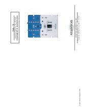
PostScript Picture<br />
MOD-1_callouts.eps<br />
MOD1 - REMOVABLE EFFECTS MODULE<br />
FRONT & BACK PANELS<br />
mixed for easy control (and cool<br />
effect). The Pitch shifter only has one<br />
parameter.<br />
20. Mix: Controls the dry/wet signal(dry<br />
= original signal, wet = processed signal).<br />
In the center position, the signal<br />
includes an exact 50/50 combination of<br />
both signals. Turning the knob to “wet”<br />
will have only the processed signal,<br />
affected by the Master volume control.<br />
It can be used to record even while the<br />
master volume is off.<br />
27. Inputs: Line and phono signal<br />
inputs for channels 1 and 2.<br />
28. Line3 Input: This extra line level<br />
input can be selected with the Mic/Line<br />
switch (29) and can be used as an<br />
extra line input or as a session input for<br />
team routines.<br />
29. Mic/Line3 switch: Used to assign<br />
the Mic/Line3 channel to either the Mic<br />
input or the Line3 input.<br />
30. Microphone input: 1/4” connector<br />
31. FX ON/OFF output: 1/4” connec -<br />
tor, Used to connect a foot pedal to turn<br />
the MOD1 effects on or off.<br />
32. Ground connector: Connects to<br />
the turntable ground connector to elim -<br />
inate electrical hum. Ground connec -<br />
tors usually supplied with turntables<br />
33. Mono/Stereo: Switches the mixer<br />
PostScript Picture<br />
BASE_callouts.eps<br />
FRONT & BACK PANELS (CONT’D)<br />
output from stereo to mono (use it in<br />
case a channel fails on the power amp,<br />
cartridge, etc. it can be very useful<br />
live).<br />
34. Input Fader Curve Adjustment:<br />
Adjusts the curve of the input faders<br />
between quick (6dB), normal (20dB),<br />
or long (30dB) fade.<br />
35. Input Fader Reverse: Reverses<br />
the direction of each respective input<br />
channel fader. Includes bi-color LED to<br />
indicate the status of the reverse func -<br />
tion. When LED is green, the fader is<br />
normal. When LED is red, the fader<br />
direction is reversed.<br />
36. Crossfader Curve adjustment:<br />
Adjusts the shape of the crossfader<br />
curve from a quick cut for scratching<br />
and cutting to a longer fade for mixing.<br />
37. Crossfader Reverse: Reverses