Computational Mechanics Research and Support for Aerodynamics ...
Computational Mechanics Research and Support for Aerodynamics ...
Computational Mechanics Research and Support for Aerodynamics ...

You also want an ePaper? Increase the reach of your titles
YUMPU automatically turns print PDFs into web optimized ePapers that Google loves.
In Figure 2.15 the velocity <strong>and</strong> the position corresponding to the line probe (at a crest) are represented<br />
on the x <strong>and</strong> y axis of the plot. With a mesh base size of 5mm, the velocity profiles are very regular. For<br />
the mesh case where the base size is 5mm <strong>and</strong> no refinement in the corrugated section, the maximum<br />
velocity is a little higher than cases with further refinement in the corrugations. For mesh cases 5 <strong>and</strong> 6<br />
where the mesh is further refined along the corrugated section in the order of 80% <strong>and</strong> 66% respectively<br />
there is not much difference in the nature of the velocity profiles although there is large difference in<br />
the number of computational cells. Mesh case 5 consists of 249,174 cells <strong>and</strong> mesh case 6 consists of<br />
887,369 cells. Mesh 5 is reasonably mesh independent upon further refinement <strong>and</strong> consumes a<br />
reasonably small amount of computational resources.<br />
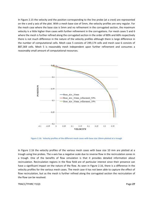
Figure 2.16: Velocity profiles of the different mesh cases with base size 10mm plotted at a trough<br />
In Figure 2.16 the velocity profiles of the various mesh cases with base size 10 mm are plotted at a<br />
trough using line probes. The x-axis has a negative scale due to reverse flow in the recirculation zones in<br />
a trough. One of the benefits of flow simulation is that it provides detailed in<strong>for</strong>mation about<br />
recirculation. Recirculation regions in the flow field are of particular interest since their presence can<br />
have a significant impact on the nature of the flow. As seen in Figure 2.16, there is a difference in the<br />
velocity profiles <strong>for</strong> the various mesh cases. The mesh case 4 has not been able to capture the effect of<br />
flow recirculation, but as the mesh is further refined along the corrugated section the recirculation of<br />
the flow can be resolved.<br />
TRACC/TFHRC Y1Q3 Page 27