Computational Mechanics Research and Support for Aerodynamics ...
Computational Mechanics Research and Support for Aerodynamics ...
Computational Mechanics Research and Support for Aerodynamics ...

Create successful ePaper yourself
Turn your PDF publications into a flip-book with our unique Google optimized e-Paper software.
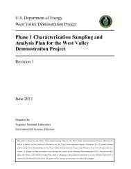
Mesh scene 2 Mesh scene 3<br />
Mesh scene 5 Mesh scene 6<br />
Figure 2.8: Mesh scenes of the various cases used <strong>for</strong> mesh refinement studies<br />
Table 2.2 below summarizes the details of the different cases considered in the mesh refinement study.<br />
For meshes 1 <strong>and</strong> 4, a uni<strong>for</strong>m mesh size distribution with a mesh size of 10 mm <strong>and</strong> 5mm respectively<br />
has been chosen, other mesh types in Table 2.2 use volume controls <strong>for</strong> meshing to achieve a finer mesh<br />
with increased number of cells near the corrugated wall region to better resolve the recirculation zones<br />
in the region. A specified mass flow rate is given at the inlet <strong>and</strong> the outlet, which are the cyclic<br />
boundaries to obtain the cyclic fully developed flow condition. A mass flow rate of 13.85 kg/s was set <strong>for</strong><br />
the cyclic boundary condition. The mass residuals decrease slightly <strong>for</strong> finer meshes, are good <strong>for</strong> all<br />
meshes, <strong>and</strong> don’t nessarily indicate the accuracy of the computation.. The accuracy of the results<br />
obtained in terms of the velocity profiles at different sections in the flow field or the visualized scenes<br />
give a better picture of sensitivity to the mesh. The degree of convergence does not indicate the amount<br />
of discretion error. When the flow is not parallel to the cells in the mesh, there is some difference in the<br />
mass flow obtained by integrating over the cyclic boundary interface <strong>and</strong> a plane midway through the<br />
culvert section which gives some discretion error. The corrugations cause the flow streamlines to curve<br />
<strong>and</strong> not remain parallel to the mesh. Column 5 from Table 2.2 indicates the percent deviation of the<br />
mass flow across the boundary <strong>and</strong> mid plane. These values are all very good except <strong>for</strong> the coarsest<br />
mesh.<br />
TRACC/TFHRC Y1Q3 Page 20