Computational Mechanics Research and Support for Aerodynamics ...
Computational Mechanics Research and Support for Aerodynamics ...
Computational Mechanics Research and Support for Aerodynamics ...

Create successful ePaper yourself
Turn your PDF publications into a flip-book with our unique Google optimized e-Paper software.
efine the rate function to improve the match to experimental results using the results of the CFD<br />
simulation. The CFD simulation yields the bed shear at the current scour depth at each time step. The<br />
laboratory time at which the simulated scour depth was reached can be computed from Equation (2.3),<br />
<strong>for</strong> times greater than 1800 s. Also <strong>for</strong> times greater than 1800 s, the bed recession rate at the depth<br />
from the simulation can be calculated from Equation (2.4). This procedure yields a new value <strong>for</strong> bed<br />
recession rate corresponding to the bed shear at the maximum depth <strong>for</strong> each time step. These new<br />
values can be used to improve the parameters <strong>for</strong> the entrainment rate function. As noted in Section<br />
2.1, there are no experimental data <strong>for</strong> the first 1800 s, <strong>and</strong> the erosion rate at the deepest point as a<br />
function of time, Equation (2.4) has a physically unrealistic singular point at time equal to zero. In the<br />
absence of experimental data, some reasonable assumptions are needed to determine an erosion rate<br />
as a function of bed shear during the first 1800 s that will result in the simulation matching the<br />
experimental scour depth within the range of uncertainty at 1800 s. The procedure <strong>for</strong> achieving this<br />
goal is currently under development.<br />
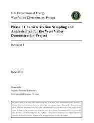
The streamwise velocity distribution in the vicinity of the flooded bridge deck at the initial unscoured<br />
state is shown in Figure 2.4. It clearly shows accelerated flow under the deck <strong>and</strong> a much higher velocity<br />
near the bed than in the upstream. Figure 2.5 shows the streamwise velocity distribution after the scour<br />
hole has fully <strong>for</strong>med. The accelerated flow under the deck is significantly reduced, <strong>and</strong> the near bed<br />
boundary layer is thicker, which yields a reduced shear stress peak under the bed <strong>and</strong> near zero erosion<br />
rate.<br />
Figure 2.4: Initial streamwise velocity distribution around bridge deck<br />
TRACC/TFHRC Y1Q3 Page 15