Automatic Transfer Switch from 63 to 3200 A - Tehnounion
Automatic Transfer Switch from 63 to 3200 A - Tehnounion
Automatic Transfer Switch from 63 to 3200 A - Tehnounion

You also want an ePaper? Increase the reach of your titles
YUMPU automatically turns print PDFs into web optimized ePapers that Google loves.
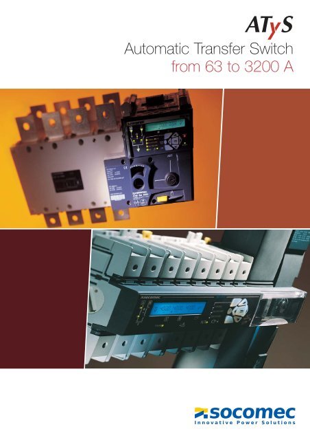
<strong>Au<strong>to</strong>matic</strong> <strong>Transfer</strong> <strong>Switch</strong><br />
<strong>from</strong> <strong>63</strong> <strong>to</strong> <strong>3200</strong> A
Changeover switches<br />
Modular <strong>Au<strong>to</strong>matic</strong> <strong>Transfer</strong> <strong>Switch</strong><br />
<strong>from</strong> <strong>63</strong> <strong>to</strong> 160 A<br />
CHANGEOVER<br />
Two mechanically interlocked<br />
power switches.<br />
OPERATION<br />
A configurable au<strong>to</strong>matic control<br />
associated with an emergency<br />
manual operation.<br />
MONITORING &<br />
CONTROL<br />
A built-in configuration and control<br />
interface, simple or advanced.<br />
INSTALLATION<br />
A modular product adapted <strong>to</strong> any<br />
type of enclosure integration.<br />
atysm_007_a<br />
ADAPTED RANGE<br />
ATyS M proposes a complete range of products <strong>to</strong> meet all break<br />
before make transfer requirements.<br />
> ATyS M 3s: remote controlled switch<br />
> ATyS M 6s: simple and ergonomic<br />
Configurable au<strong>to</strong>matic transfer switch cycles, with stable positions.<br />
atysm_029_b<br />
> ATyS M 6e: advanced and programmable<br />
Fully programmable au<strong>to</strong>matic transfer switch cycles ensuring<br />
position stability or return <strong>to</strong> 0 position feature upon loss of network.<br />
atysm_031_b<br />
atysm_030_b<br />
A PRODUCT FOR ALL CHANGEOVER APPLICATIONS FROM <strong>63</strong> TO 160 A<br />
> Network/Genera<strong>to</strong>r Set<br />
• Genera<strong>to</strong>r set control<br />
• ATS solution<br />
> Network/Network<br />
• Building services<br />
• Control with or without priority<br />
ATyS M 3s<br />
GS<br />
ATyS M 6s<br />
ATyS M 6e<br />
GS<br />
ATyS M 6e<br />
ATyS M 6s<br />
Non-critical<br />
loads<br />
Critical<br />
loads<br />
UPS<br />
atysm_003_a_gb<br />
Non-critical<br />
loads<br />
Critical<br />
loads<br />
UPS<br />
atysm_004_a_gb<br />
ATyS M 6e<br />
atysm_005_a_gb<br />
Non-critical<br />
loads<br />
Critical<br />
loads<br />
UPS<br />
atysm_006_a_gb<br />
A. 2
AN OPTIMISED SWITCHING SYSTEM<br />
A COMPLETE RANGE OF ACCESSORIES<br />
> <strong>Switch</strong>ing technology<br />
• An on load switch disconnec<strong>to</strong>r providing<br />
safety isolation combined with high making<br />
and breaking characteristics<br />
• Safety isolation<br />
• Stable positions<br />
> A new switching module combining<br />
• High dynamic withstand<br />
• Fast operation<br />
• High number of operations<br />
> Two power switches<br />
Mechanically and electrically<br />
interlocked<br />
SI<br />
SII<br />
taysm_002_a atysm_038_a<br />
> Voltage tap<br />
atysm_021_a<br />
atysm_035_a<br />
> Bridging bar<br />
> Auxiliary contacts > Terminal shrouds<br />
atysm_019_a<br />
atysm_027_a<br />
FAST ELECTRICAL OPERATION<br />
> Sealable cover<br />
(ATyS M 6s)<br />
> Remote display<br />
(ATyS M 6e)<br />
> Electromagnetic control<br />
Enables fast I - II switching operation<br />
> An available energy s<strong>to</strong>rage<br />
device<br />
Enables return <strong>to</strong> 0 position feature<br />
upon loss of network without any<br />
power source available<br />
atysm_037_a<br />
FLEXIBLE INTEGRATION<br />
atysm_033_a_1_cat<br />
atys_565_c<br />
OPERATION<br />
atysm_014_b_1_cat<br />
atysm_015_b_1_cat<br />
atysm_016_b_1_cat<br />
> <strong>Au<strong>to</strong>matic</strong>/Manual<br />
operating mode<br />
selection via the<br />
protective cover<br />
> Operation using<br />
a standard allen<br />
key<br />
> Padlocking function<br />
configurable<br />
in position 0 or in<br />
all three positions<br />
I - 0 - II<br />
A DEDICATED CONTROL LOGIC<br />
<strong>Au<strong>to</strong>matic</strong> mode (AUT)<br />
Network 1 failure<br />
MFT<br />
Genera<strong>to</strong>r start<br />
Network 2 availability<br />
DTT<br />
<strong>Switch</strong> <strong>to</strong> position 0<br />
0MF<br />
<strong>Switch</strong> <strong>to</strong> position 1<br />
0MR<br />
<strong>Switch</strong> <strong>to</strong> position 0<br />
Semi au<strong>to</strong>matic mode<br />
yes<br />
MRT<br />
<strong>Switch</strong> <strong>to</strong> position 2 Network 1 availability<br />
no<br />
Example (genera<strong>to</strong>r application):<br />
Network 1 : priority power source<br />
Network 2 : backup power source<br />
Genera<strong>to</strong>r s<strong>to</strong>p<br />
CDT<br />
Manual<br />
operation<br />
atys_028_c_gb<br />
ATyS M integrated in<strong>to</strong> a modular DIN enclosure (Din rail or back<br />
plate mounted).<br />
appli_179_b appli_177_a<br />
A. 3
Changeover switches<br />
SELECTION GUIDE<br />
ATyS <strong>63</strong> <strong>to</strong> <strong>3200</strong> A<br />
Power<br />
M<br />
Command<br />
atysm_013_a_2_cat<br />
atysm_012_a_2_cat<br />
atysm_007_a_2_cat<br />
ATyS M 3s ATyS M 6s ATyS M 6e<br />
<strong>63</strong> <strong>to</strong> 160 A <strong>63</strong> <strong>to</strong> 160 A <strong>63</strong> <strong>to</strong> 160 A<br />
Normal/backup transfer with an external au<strong>to</strong>matic control<br />
•<br />
Normal/backup transfer with an internal au<strong>to</strong>matic control (ATS)<br />
Load changeover<br />
•<br />
• •<br />
APPLICATIONS<br />
External controller: Main/Main or Genset/Main applications<br />
External controller: Dual genset application<br />
CHARACTERISTICS<br />
AUXILIARY POWER SUPPLY<br />
Version 1 AC power supply<br />
Version 2 AC power supplies<br />
Version 1 DC power supply<br />
OPERATION<br />
Volt free auxiliary contacts for the I, 0, II positions<br />
•<br />
<strong>Au<strong>to</strong>matic</strong> for I, 0, II positions • •<br />
MAN / AUT selec<strong>to</strong>r switch • • •<br />
MONITORING<br />
Main network : 3U • •<br />
Emergency network : 3U • •<br />
Main network: 1U<br />
Emergency network : 1U<br />
CONFIGURATION<br />
Choice of logic: contac<strong>to</strong>r or impulse<br />
•<br />
Upper and lower thresholds, associated hysteresis • •<br />
Operating time delays • •<br />
Network priority • •<br />
FRONT DISPLAY<br />
Status of supplies, positions, commands, faults, padlocking • •<br />
U<br />
•<br />
F<br />
•<br />
3I, P, Q, S, PF, In moni<strong>to</strong>red<br />
CONTROL / OPERATION<br />
Position I and II auxiliary contacts accessory accessory accessory<br />
Position 0 auxiliary contacts accessory accessory accessory<br />
Padlock and MAN / AUT information auxiliary contacts<br />
•<br />
Genera<strong>to</strong>r start-up output auxiliary contacts • •<br />
Fault relay output auxiliary contacts • •<br />
RS485 (JBUS MODBUS ® ) - accessory<br />
2 input / 2 output - accessory<br />
REMOTE INTERFACE (ACCESSORY)<br />
ATyS D10 display device<br />
ATyS D20 display and control device<br />
Load<br />
Example: between a<br />
transformer and a genset<br />
•<br />
•<br />
•<br />
PAGES<br />
see page<br />
A.12<br />
see page<br />
A.12<br />
see page<br />
A.12<br />
A. 4<br />
SOCOMEC general catalogue
atys_003_a_3_cat<br />
atys_103_a_1_cat<br />
atys_097_b_2_cat<br />
ATyS 3s ATyS 3e ATyS 6e ATyS 6m ATyS C30 ATyS C40<br />
125 <strong>to</strong> 1800 A 125 <strong>to</strong> <strong>3200</strong> A 125 <strong>to</strong> <strong>3200</strong> A 125 <strong>to</strong> <strong>3200</strong> A<br />
• •<br />
• •<br />
• •<br />
•<br />
•<br />
atys_102_a_2_cat<br />
atys_448_b_2_cat<br />
atys_599_b_2_cat<br />
acces_205_a_1_cat<br />
atys_606_a_2_cat<br />
Bridging bars<br />
Voltage sensing<br />
and power<br />
supply kit<br />
•<br />
• • • •<br />
• •<br />
• • • •<br />
• •<br />
• • • •<br />
atys_565_c_2_cat<br />
• • •<br />
• •<br />
•<br />
• •<br />
Remote<br />
interface<br />
• • • • • •<br />
• • • •<br />
• • • •<br />
• • • •<br />
• • • • •<br />
• •<br />
• •<br />
•<br />
see page<br />
A.17<br />
• • • •<br />
• • •<br />
• • •<br />
• • • •<br />
• •<br />
accessory accessory<br />
accessory accessory • (std)<br />
• • •<br />
• • •<br />
couv_128_a_2_cat<br />
ATyS VISION<br />
software<br />
see page<br />
A.12<br />
see page<br />
A.12<br />
see page<br />
A.12<br />
see page<br />
A.12<br />
see page<br />
A.36<br />
see page<br />
A.36<br />
see page<br />
A.38<br />
SOCOMEC general catalogue A. 5
Changeover switches<br />
The ATyS range<br />
▲<br />
The ATyS range<br />
ATyS<br />
ATyS C30 / ATyS C40<br />
ATyS VISION software<br />
Other changeover switches<br />
Overview<br />
The ATyS remote controlled and au<strong>to</strong>matic transfer switch family<br />
proposes a complete range of low voltage compact changeover<br />
switches and accessories.<br />
The new ATyS M family dedicated <strong>to</strong> applications below 160 A<br />
retains key features and characteristics of the existing ATyS<br />
product range bringing some innovation.<br />
ATyS range is now also available up <strong>to</strong> <strong>3200</strong>A <strong>to</strong> complete the<br />
family for higher current applications.<br />
▲<br />
Operating principle<br />
<strong>Au<strong>to</strong>matic</strong> mode (AUT)<br />
Network 1 failure<br />
MFT<br />
Genera<strong>to</strong>r start<br />
<strong>Switch</strong> <strong>to</strong> position 1<br />
Genera<strong>to</strong>r s<strong>to</strong>p<br />
CDT<br />
ATyS are composed of two mechanically and electrically<br />
interlocked switches.<br />
All the products are fitted with emergency manual operation.<br />
• either remotely controlled: ATyS M 3 and ATyS 3 products are<br />
driven by volt-free dry contacts allowing switching operation<br />
between position I, 0 or II, <strong>from</strong> an external control logic or a plc<br />
(control relays type ATyS C30).<br />
• or au<strong>to</strong>maticaly controlled: ATyS M 6 and ATyS 6 are<br />
dedicated <strong>to</strong> break before make au<strong>to</strong>matic transfer applications.<br />
They integrate control relays, timers and test functions <strong>to</strong><br />
manage a Normal/Backup switching operation between 2<br />
networks or a genera<strong>to</strong>r set and a network.<br />
atys_028_c_1_gb_cat<br />
Network 2 availability<br />
DTT<br />
<strong>Switch</strong> <strong>to</strong> position 0<br />
0MF<br />
0MR<br />
<strong>Switch</strong> <strong>to</strong> position 0<br />
Semi au<strong>to</strong>matic mode<br />
yes<br />
MRT<br />
<strong>Switch</strong> <strong>to</strong> position 2 Network 1 availability<br />
no<br />
Example (genera<strong>to</strong>r application):<br />
Network 1 : priority power source<br />
Network 2 : backup power source<br />
Manual<br />
operation<br />
Normal / Emergency Timers<br />
• MFT: Main failure timer (0-60s)<br />
• DTT: Delay <strong>to</strong> transfer on Genera<strong>to</strong>r set timer (0-60s)<br />
• 0MF: 0 position stay before transfer on Genera<strong>to</strong>r set (0-20s)<br />
• MRT: Main return timer before retransfer (0-30min.)<br />
• 0MR: 0 position stay before re transfer on Main (0-20s)<br />
• CDT: Cool down timer before Genera<strong>to</strong>r set shutdown (0-10 min).<br />
▲<br />
ATyS M: Modular au<strong>to</strong>matic transfer switches <strong>from</strong> <strong>63</strong> <strong>to</strong> 160 A<br />
Description<br />
ATyS M electrical operation utilises coil technology <strong>to</strong> achieve fast<br />
transfer cycles.<br />
ATyS M 6e brings a new innovative solution allowing the<br />
changeover <strong>to</strong> be driven in<strong>to</strong> 0 position without any power supply<br />
available.<br />
▲<br />
Manual operation<br />
atysm_014_b_1_cat<br />
AUT/ MAN sealable cover<br />
Opening the front cover disables<br />
electrical or au<strong>to</strong>matic operations and<br />
enables manual or padlocking facilities.<br />
Indication of the front cover status<br />
(opened or closed) is available on the<br />
ATyS M via a dedicated auxiliary<br />
contact.<br />
atysm_016_b_1_cat<br />
Padlocking facility<br />
It is possible as standard <strong>to</strong> padlock the<br />
ATyS M product in 0 position.<br />
3 positions padlocking is configurable on<br />
the product before its installation.<br />
atysm_015_b_1_cat<br />
Emergency manual operation<br />
ATyS M products can be manually<br />
operated in any of the three available<br />
positions (I,0,II) using a standard allen<br />
key provided once the cover is opened.<br />
A. 6<br />
SOCOMEC general catalogue
Changeover switches<br />
The ATyS range<br />
▲<br />
atysm_025_a_1_cat<br />
Main accessories<br />
Bridging bar<br />
To provide a common connection point<br />
on the load side:<br />
- insulated IP2x<br />
- leaves the cable terminals free by using<br />
a dedicated fixing location.<br />
atysm_028_a_1_cat<br />
Auxiliary contacts<br />
Each product can be equipped with<br />
2 auxiliary contacts. It integrates one<br />
NO/NC contact per position (I, 0, II).<br />
Characteristics: 250 VAC - 5A maximum.<br />
atysm_026_a_1_cat<br />
Single phase voltage sensing tap<br />
Allows up <strong>to</strong> 2x 1.5 mm 2 . sensing cables<br />
connection on main power terminals<br />
keeping power cables capacity<br />
complete. They can be mounted in any<br />
of the power terminals but not<br />
simultaneously with the bridging bar.<br />
atys_565_c_2_cat<br />
Remote interfaces ATyS D10 or D20<br />
To display source availability and<br />
changeover state on the front of a panel.<br />
RJ45 cable connection between<br />
ATyS M 6e only, and ATyS D10 / D20.<br />
atysm_027_a_1_cat<br />
Terminal shroud<br />
Provides protection against direct<br />
contact with the connection terminals or<br />
parts. A specific front hole enables<br />
access <strong>to</strong> terminals’ tightening screws<br />
for thermographic measurement or<br />
voltage sensing.<br />
The same accessory can be mounted on<br />
the incoming or outgoing side of the<br />
products.<br />
atysm_043_a<br />
Sealable cover<br />
Controls settings cover <strong>to</strong> avoid<br />
ATyS M 6s parameters access due<br />
<strong>to</strong> a sealable facility.<br />
▲<br />
ATyS M 3s: Remote controlled changeover<br />
Power supply<br />
ATyS M 3s is equipped with two independent 230 VAC<br />
(176-288 VAC), 50/60 Hz (45-65 Hz) power inputs.<br />
• These two supplies can be individually connected <strong>to</strong> source<br />
I and source II power inputs:<br />
- Power supply I must be available <strong>to</strong> reach position I<br />
- Power supply II must be available <strong>to</strong> reach position II.<br />
The 0 position is in this type off control scheme only a transi<strong>to</strong>ry<br />
position.<br />
• Use of a SOCOMEC DPS unit (Double Power Supply), or of an<br />
independent power supply will allow control of the product in<br />
any of the three positions as soon as power is available on the<br />
product power inputs.<br />
atysm_029_b<br />
▲<br />
atysm_040_c_1_x_cat<br />
Wiring diagram<br />
A<br />
B<br />
B<br />
B<br />
B<br />
6 6 6 6<br />
317 315 314 313 202 201 102 101<br />
1 3 D<br />
2<br />
5<br />
4<br />
or<br />
C<br />
▲<br />
Command<br />
Positions command is realised via external volt free contacts<br />
(example ATyS C30 controller). Position remains stable in case of<br />
power supplies loss (switch technology).<br />
Impulse control mode<br />
• A minimum 30 ms impulse required.<br />
• I and II commands have priority over 0 command (different <strong>from</strong><br />
ATyS).<br />
• The first command (order) received has priority for its duration.<br />
Contac<strong>to</strong>r control mode<br />
• The 0 command must be maintained <strong>to</strong> enable contac<strong>to</strong>r control<br />
mode (strap between 0 / C command and common terminal).<br />
• In case of position I or position II command loss, the product<br />
returns <strong>to</strong> position 0 (only if the required power input <strong>to</strong> allow the<br />
operation is available).<br />
1 : control position I<br />
2 : control position II<br />
3 : control position 0 / C<br />
4 : power supply I (230 VAC)<br />
5 : power supply II (230 VAC)<br />
6 : voltage tap<br />
A : bridging bar (accessories)<br />
B : single phase voltage sensing tap (accessories)<br />
C : auxiliary contacts - 1 AC per position I, 0, II ( accessories)<br />
D : F1 / F2 = fuse 10 A gG.<br />
atysm_042_a_1_gb_cat<br />
order I<br />
order O<br />
order II<br />
position I<br />
position O<br />
position II<br />
SOCOMEC general catalogue<br />
A. 7
Changeover switches<br />
The ATyS range<br />
▲<br />
The ATyS range<br />
ATyS<br />
ATyS C30 / ATyS C40<br />
ATyS VISION software<br />
Other changeover switches<br />
▲<br />
▲<br />
ATyS M 6: <strong>Au<strong>to</strong>matic</strong> <strong>Transfer</strong> <strong>Switch</strong><br />
Characteristics<br />
Power supply<br />
ATyS M 6 products are self power supplied <strong>from</strong> incoming<br />
supplies: 230 VAC (176-288 VAC), 50/60 Hz (45-65 Hz).<br />
Two different versions are available:<br />
• 230 / 400 VAC with neutral conduc<strong>to</strong>r distributed: product is<br />
power supplied between phase and neutral.<br />
• 127 / 230 VAC with or without neutral conduc<strong>to</strong>r distributed:<br />
product is power supplied between 2 phases.<br />
The neutral conduc<strong>to</strong>r can be connected <strong>to</strong> the left or right side of<br />
each switch.<br />
Return <strong>to</strong> 0 position feature (only on ATyS M 6e)<br />
With ATyS M 6e it is possible <strong>to</strong> return au<strong>to</strong>matically <strong>to</strong> the 0<br />
position after a power supply loss.<br />
An energy s<strong>to</strong>rage device enables return <strong>to</strong> the 0 position even<br />
with no voltage available on the power supply inputs.<br />
Operation<br />
ATyS M 6s<br />
Single phase or three phases voltage and frequency control<br />
on networks I and II<br />
ATyS M 6s<br />
• Linked over/under voltage and over/under frequency thresholds<br />
<strong>from</strong> 5 <strong>to</strong> 20% of Un and 3 <strong>to</strong> 10% of f n .<br />
• Hysteresis levels fixed at 80% of the set up threshold.<br />
ATyS M 6e<br />
• Independent over/under voltage and over/under frequency<br />
thresholds +/-20% of nominal values.<br />
• Configurable associated hysterisis thresholds.<br />
• Phase rotation and unbalance control.<br />
Metering only on ATyS M 6e<br />
• 3 phases voltage measurement on networks 1 and 2 .<br />
• Frequency measurement on networks 1 and 2 .<br />
• Timers display and count down.<br />
ATyS M 6e<br />
atysm_031_b<br />
atysm_030_b<br />
▲<br />
4 potentiometers<br />
• Nominal voltage configuration.<br />
• Voltage and frequency thresholds configuration.<br />
• Operating cycles timers configuration: MFT (0 <strong>to</strong> 60s), DTT (5s),<br />
MRT (0 <strong>to</strong> 30 min), CDT (4 min).<br />
4 dip switches<br />
50 or 60 Hz, single or three phases, 2 seconds 0 position<br />
transition during I-II transfer cycles (0MR/0MF), Network / Network<br />
or Network / Genset application.<br />
4 leds<br />
Power supply sources availability; <strong>Au<strong>to</strong>matic</strong> mode (cover<br />
opened); Fault (command order and position not reached).<br />
3 external command inputs<br />
• <strong>Au<strong>to</strong>matic</strong> mode inhibition.<br />
• Remote test on load (or priority change).<br />
• Manual retransfer <strong>from</strong> emergency source <strong>to</strong> main source<br />
(validation required).<br />
1 NO bi-stable output relay for genera<strong>to</strong>r start /s<strong>to</strong>p command<br />
(30 VDC / 2 A).<br />
1 NO fault relay (250 VAC/ 0,5 A).<br />
Wiring diagram<br />
8<br />
Display + Keypad<br />
• Parameters configuration (thresholds, timers …).<br />
• 3 phases voltage and frequency for source I and II, timers,<br />
number of cycles and last event display.<br />
• Tests and positions control facilities.<br />
Leds<br />
Power On; Sources availability; Changeover position; “MAN / AUT”<br />
mode; Test / Control operation; Fault.<br />
3 configurable inputs<br />
<strong>Au<strong>to</strong>matic</strong> mode inhibition; Test on load and off load; Manual<br />
retransfer; Changeover position control; Network priority change.<br />
1 NO bi-stable output relay for genera<strong>to</strong>r start /s<strong>to</strong>p command<br />
(30 VDC / 2 A).<br />
2 programmable output relays (250 VAC / 3 A)<br />
Source I or II availability; Load shedding output; Fault relay.<br />
ATyS D10 or D20 remote interface connection.<br />
1<br />
2<br />
priority source<br />
backup source<br />
atysm_041_b_1_x_cat<br />
A<br />
1 2<br />
ATyS M 6s<br />
207 208 209 210 <strong>63</strong> 64 73 74<br />
1 3<br />
2<br />
6<br />
RJ<br />
7<br />
B<br />
1 3<br />
2<br />
ATyS M 6e<br />
207 208 209 210 43 44 53 54 <strong>63</strong> 64 73 74<br />
4<br />
5<br />
6<br />
7<br />
ATyS M 6s<br />
1 : manual retransfer / priority change<br />
2 : test on load<br />
3 : au<strong>to</strong>matic mode inhibition<br />
6 : fault relay<br />
7 : genset start / s<strong>to</strong>p relay<br />
ATyS M 6e<br />
1 - 2 - 3 : programmable input<br />
4 : “non au<strong>to</strong>matic” mode output<br />
5 - 6 : programmable output<br />
7 : genset start / s<strong>to</strong>p relay<br />
8 : RJ 45 ATyS D10/D20 remote interface connection<br />
A : bridging bar (accessory)<br />
B : auxiliary contacts (accessory) - 1 AC per position I, 0, II.<br />
A. 8<br />
SOCOMEC general catalogue
Changeover switches<br />
The ATyS range<br />
▲<br />
▲<br />
atys_097_b_1_cat<br />
atys_013_a_1_cat<br />
▲<br />
atys_565_c_2_cat<br />
▲<br />
▲<br />
ATyS: <strong>from</strong> 125 <strong>to</strong> <strong>3200</strong> A<br />
Description<br />
ATyS products are mechanically interlocked, back <strong>to</strong> back<br />
mounted, load break switches. Their compact design guarantees<br />
position stability and high dynamic withstand.<br />
Manual operation<br />
Main accessories<br />
Power supply<br />
Backup manual operation<br />
The product can still be switched without<br />
any power source using the manual<br />
operation. The handle (supplied with the<br />
product) allows direct operation of the<br />
changeover shaft. The switch cannot be<br />
manually operated in au<strong>to</strong>matic mode<br />
(AUT) or padlocked.<br />
• ATyS 3s: one power input 230 VAC (176-288 VAC), 50/60 Hz<br />
(45-65 Hz).<br />
• ATyS 3e, 6e, 6m: two power inputs VAC (176-288 VAC), 50/60 Hz<br />
(45-65 Hz), one defined as power source 1 and the other as<br />
backup power source 2 . Electrical operation of the product is<br />
possible as soon as one of the power supplies is available.<br />
Control logic<br />
AUT / MAN command<br />
An AUT / MAN selec<strong>to</strong>r inhibits au<strong>to</strong>matic<br />
operation and allows handle use when<br />
positioned in manual mode. This selec<strong>to</strong>r<br />
is key type on ATyS 3e, 6e and 6m.<br />
Remote control interface<br />
Enables operation, configuration and display<br />
of all the functions remotely. It can be<br />
connected <strong>to</strong> an ATyS 6e or 6m via an RJ45<br />
type link. When connected, all features<br />
available on the front of the product are<br />
inhibited. Maximum connection distance:<br />
3m. 2 modeles: ATyS D10 (visualisation) and<br />
ATyS D20 (visualisation and control).<br />
atys_008_a_1_cat<br />
svrmo_077_c_1_gb_cat<br />
Simplified diagram<br />
AUT position<br />
priority power source<br />
stand by power source<br />
switching operation possibility<br />
1<br />
2<br />
Padlocking<br />
Up <strong>to</strong> three padlocks can be used <strong>to</strong> lock<br />
the device.<br />
When padlocked:<br />
• manual operation is not possible<br />
• electrical controls are disabled.<br />
Padlocking in the 3 positions I, 0 and II,<br />
available in option.<br />
General<br />
• The switching operation can be driven by an external dry contact. “Pulsed contact logic” (impulse) or “maintained contact logic”<br />
(contac<strong>to</strong>r), are both recognised on the control inputs.<br />
• The type of logic must be selected during configuration (programming).<br />
• Priorities: the first order received has priority as long as it is present. A zero command has always priority, excepted in case of controls<br />
inhibition.<br />
• ATyS 3e integrates number of operation counter and allows optional communication or inputs/outputs module connection.<br />
atys_011_a_1_cat<br />
Voltage sensing and power supply kit<br />
Allows voltage sensing and power supply<br />
connections through a controlled routing of<br />
the conduc<strong>to</strong>rs, in order <strong>to</strong> avoid the use of<br />
specific protection devices (fuse / mcb).<br />
Impulse logic<br />
• The switching command is a pulsed dry contact lasting at least<br />
100 ms.<br />
• When the order disappears, the product remains in position.The<br />
impulse can be of infinite duration without causing any<br />
disturbance.<br />
order I<br />
order O<br />
order II<br />
Contac<strong>to</strong>r logic<br />
• The transfer command is a maintained dry contact.<br />
• If command I or II disappears, the device returns <strong>to</strong> zero<br />
position, if power supply is available.<br />
• A 0 command drives the device in<strong>to</strong> zero position, irrespective of<br />
the status of the I and II commands.<br />
order I<br />
order O<br />
order II<br />
svrmo_079_b_1_gb_cat<br />
position I<br />
position O<br />
position II<br />
atys_024_a_1_gb_cat<br />
position I<br />
position O<br />
position II<br />
SOCOMEC general catalogue<br />
A. 9
Changeover switches<br />
The ATyS range<br />
▲<br />
The ATyS range<br />
ATyS<br />
ATyS C30 / ATyS C40<br />
ATyS VISION software<br />
Other changeover switches<br />
▲<br />
Wiring diagram<br />
ATyS 3s<br />
ATyS 3e<br />
1 2<br />
1<br />
2<br />
atys_025_e_1_x_cat<br />
5 6<br />
313 314 315 316 317 101 102<br />
4<br />
3 2 1<br />
DPS 7<br />
atys_094_d_1_x_cat<br />
202 201<br />
11<br />
64 <strong>63</strong> 317 316 315 314 313 102 101<br />
5<br />
4<br />
3<br />
2<br />
1<br />
10 9 8<br />
7<br />
6<br />
13 14 24 34 43 44 53 54<br />
power source 1<br />
power source 2<br />
1: control position 0<br />
2: control position I<br />
3: control position II<br />
4: configuration of the control logic<br />
5 : NO/NC position and prebreaking<br />
contact for position I<br />
6: NO/NC position and prebreaking<br />
contact for position II<br />
7 : Double Power Supply (accessory).<br />
power source 1<br />
power source 2<br />
1 : control position 0<br />
2 : control position I<br />
3 : control position II<br />
4 : inhibition of the control position<br />
5 : fault relays<br />
6 : auxiliary contact, closed when<br />
the switch is padlocked<br />
7 : auxiliary contact, closed when<br />
the switch is in “AUT” mode<br />
8 : auxiliary contact, closed when<br />
the switch is in position 0<br />
9 : auxiliary contact, closed when<br />
the switch is in position II<br />
10 : auxiliary contact, closed when<br />
the switch is in position I<br />
11 : slots for optional modules.<br />
▲<br />
▲<br />
atys_679_a_1_x_cat<br />
ATyS 6: <strong>Au<strong>to</strong>matic</strong> <strong>Transfer</strong> <strong>Switch</strong>es<br />
General features<br />
Single or three phases control on networks I and II<br />
• Independent Under/ Over voltage and Under / Over frequency<br />
thresholds: +/- 20% of nominal value.<br />
• Adjustable hysteresis thresholds.<br />
• Phase rotation control.<br />
Operation<br />
Display + keypad<br />
• Setup and Thresholds configuration;<br />
• Timers configuration MFT (0-60 s), DTT (0-60 s), 0MF (0-20 s),<br />
MRT (0-60 min.), 0MR (0-20 s), CDT (0- 10 min.).<br />
• Voltage, Frequency, Timers moni<strong>to</strong>ring.<br />
• Test and positions control operations.<br />
Leds<br />
Power on; Fault; Sources availability; Changeover position;<br />
AUT mode; Test and control modes of operation.<br />
Metering<br />
• 3U on network 1 and 2 .<br />
• Frequency on network 1 and 2 .<br />
• Normal/Emergency timers.<br />
• 3I, In, P, Q, S, PF (3 phases) on ATyS 6m.<br />
1 configurable genera<strong>to</strong>r set bi-stable start/s<strong>to</strong>p relay<br />
(30 VDC, 5 A, AC1).<br />
1 NO fault relay activated in case of changeover position<br />
ordered and not reached (30 VDC, 5 A, AC1).<br />
Control modes<br />
• Test on-load (load transfer): allows loss of main’s network<br />
simulation. The complete au<strong>to</strong>matic cycle is then followed.<br />
Can be activated <strong>from</strong> the keypad of the device or remotely <strong>from</strong><br />
an external dry contact.<br />
• Test off-load (without load transfer): allows a genera<strong>to</strong>r set start<br />
and s<strong>to</strong>p operation.<br />
Can be activated <strong>from</strong> the keypad of the device.<br />
• Control I, 0, II: allows the product <strong>to</strong> be driven in<strong>to</strong> one of the<br />
positions ; the au<strong>to</strong>matic cycle is then no longer active.<br />
Can be activated <strong>from</strong> the keypad of the device’s front or using<br />
and external dry contact.<br />
• Semi au<strong>to</strong>matic: when this mode is active, any transfer back <strong>to</strong><br />
the main network must be acknowledged on the keypad of the<br />
product or via an optional input contact.<br />
• One input <strong>to</strong> control backup source changeover (when DTT<br />
timer = max value). Example: changeover operation on multiple<br />
genera<strong>to</strong>r sources after their synchronisation.<br />
A. 10<br />
SOCOMEC general catalogue
2<br />
1<br />
Changeover switches<br />
The ATyS range<br />
▲<br />
Simplified wiring diagram<br />
atys_026_d_1_x_cat<br />
ATyS 6e / ATyS6m<br />
F2<br />
13<br />
11<br />
10<br />
12<br />
201 202<br />
203 204 205 206 207 208 209 210 73 74<br />
Power 230 VAC<br />
Voltage sensing<br />
L1 L2 L3 N<br />
16<br />
17<br />
Power 230 VAC<br />
Voltage sensing<br />
L1 L2 L3 N<br />
RJ 64 <strong>63</strong> 317 316 315 314 313 106 105 104 103<br />
102 101<br />
4<br />
2<br />
14<br />
3<br />
1<br />
F1<br />
15<br />
1: control position 0<br />
2: control position I<br />
3: control position II<br />
4 : remote command<br />
5: auxiliary contact, closed when the<br />
switch is in position I<br />
6: auxiliary contact, closed when the<br />
switch is in position II<br />
7: auxiliary contact, closed when the<br />
switch is in position 0<br />
8: auxiliary contact, closed when the<br />
switch is in “AUT” mode<br />
9: auxiliary contact, closed when the<br />
switch is padlocked<br />
10: gen-set start and s<strong>to</strong>p command<br />
11: auxiliary power supply (for optional<br />
modules control)<br />
12: remote “test on-load ”input<br />
13: DTT inhibit input. <strong>Transfer</strong> initiated<br />
as soon as the input is closed when<br />
DTT = max. value.<br />
14: fault output<br />
15: remote control interface<br />
16: current transformers (ATyS 6m only)<br />
17: slots for optional modules.<br />
Some terminal blocks are specific <strong>to</strong><br />
the ATyS 6m versions.<br />
5 6 7 8 9<br />
13 14 24 34 43 44 53 54<br />
▲<br />
ATyS enclosed range<br />
Enclosed ATS solution<br />
coff_306_a_2_cat<br />
Enclosed dual by-pass solution<br />
atys_712_a<br />
Product range<br />
• From <strong>63</strong> <strong>to</strong> 1600 A.<br />
• 230/400 VAC +/- 20%.<br />
• 3 or 4 wires applications.<br />
Range<br />
The ATyS 3s, 6e and 6m enclosed range offer the following<br />
features:<br />
• Non-<strong>Au<strong>to</strong>matic</strong> <strong>Transfer</strong> <strong>Switch</strong> (ATyS 3s)<br />
• <strong>Au<strong>to</strong>matic</strong> <strong>Transfer</strong> <strong>Switch</strong> - ATS (ATyS 6e)<br />
• Single or dual by-pass au<strong>to</strong>matic transfer switch (ATyS 6m).<br />
Features<br />
• Compact design.<br />
• Mechanically interlocked switching.<br />
Cable entry<br />
• Top or bot<strong>to</strong>m cable entry as standard <strong>from</strong> <strong>63</strong> <strong>to</strong> 250 A.<br />
• Bot<strong>to</strong>m cable entry as standard <strong>from</strong> 400 <strong>to</strong> 1600 A.<br />
• Specific cable entry requirements available upon request.<br />
• Neutral position located on the right as standard.<br />
• Alternative options available upon request.<br />
Main accessories<br />
• Double (Self) power supply for ATyS 3 only.<br />
• 2nd position auxiliary contact.<br />
• Solid neutral.<br />
• 400 / 230 VAC transformers (on each network) for 3 phases<br />
400 VAC applications.<br />
• Panel mounted ATyS D10 or D20 remote interfaces and<br />
indication meter.<br />
SOCOMEC general catalogue<br />
A. 11
Changeover switches<br />
ATyS<br />
<strong>63</strong> <strong>to</strong> <strong>3200</strong> A<br />
▲<br />
The ATyS range<br />
ATyS<br />
ATyS C30 / ATyS C40<br />
ATyS VISION software<br />
Other changeover switches<br />
ATyS M 6e<br />
atysm_007_a_1_cat<br />
ATyS M 3s<br />
atysm_013_a_1_cat<br />
Functions<br />
ATyS products are 3 and 4-pole switches<br />
remotely controlled by volt free<br />
contacts (ATyS 3) or au<strong>to</strong>matic transfer<br />
switches (ATyS 6).<br />
They are a combination of two load-break<br />
switches mounted back <strong>to</strong> back<br />
electrically and mechanically interlocked.<br />
They provide manual switching or remote<br />
controlled source inversion or changeover<br />
under load, of two low voltage power<br />
circuits.<br />
Conformity <strong>to</strong> standards<br />
• IEC 60947-3<br />
• EN 60947-3<br />
• NBN EN 60947-3<br />
• BS EN 60947-3<br />
• GB 14048<br />
• IEC 60947-6-1<br />
• EN 60947-6-1<br />
• NBN EN 60947-6-1<br />
• BS EN 60947-6-1<br />
General characteristics<br />
• Isolation with positive break indication<br />
• On load switching<br />
• Manual emergency operation<br />
• 3 stable positions (I, 0, II) or overlapping<br />
contacts on request (I, I+II, II)<br />
• Padlocking in 0 or in all three positions<br />
(I, 0, II)<br />
• AUTO / MANU selec<strong>to</strong>r.<br />
ATyS 3s<br />
atys_102_a_1_cat<br />
atys_003_a_1_cat<br />
ATyS 6m<br />
A. 12<br />
SOCOMEC general catalogue
Changeover switches<br />
ATyS<br />
Illustrations<br />
ATyS M <strong>from</strong> <strong>63</strong> <strong>to</strong> 160 A<br />
3<br />
1<br />
2<br />
5<br />
11<br />
atys_615_a_1_x_cat atysm_032_a_1_x_cat<br />
ATyS <strong>from</strong> 125 <strong>to</strong> <strong>3200</strong> A<br />
10<br />
11<br />
12<br />
9<br />
4<br />
3<br />
13<br />
9<br />
8<br />
2<br />
5<br />
1<br />
6<br />
7<br />
4<br />
3<br />
Overview (for further details, please see the<br />
installation instructions supplied with each<br />
device).<br />
1. ATyS D10 or D20 remote interfaces<br />
(ATyS M 6e only)<br />
2. 1 or 2 auxiliary contacts<br />
3. Terminal shrouds<br />
4. Voltage sensing and power supply tap<br />
5. Bridging bars.<br />
1. Backup handle and support<br />
(included with device)<br />
2. Handle key interlocking accessories<br />
3. Door protective surround<br />
4. Additional auxiliary contacts<br />
5. Standard device<br />
6. Connecting cable for ATyS D10 or D20<br />
remote interfaces (ATyS 6)<br />
7. ATyS D10 or D20 interfaces<br />
(ATyS 6)<br />
8. Plug-in optional modules<br />
(not for ATyS 3s)<br />
9. Voltage sensing and power supply kit<br />
(ATyS 6)<br />
10. Terminal shrouds<br />
11. Bridging bars<br />
12. Mounting spacers<br />
13. Terminal screens.<br />
SOCOMEC general catalogue<br />
A. 13
Changeover switches<br />
ATyS<br />
<strong>63</strong> <strong>to</strong> <strong>3200</strong> A<br />
▲<br />
The ATyS range<br />
ATyS<br />
ATyS C30 / ATyS C40<br />
ATyS VISION software<br />
Other changeover switches<br />
References<br />
▲<br />
ATyS M 3 3<br />
atysm_013_a_2_cat<br />
atysm_026_a_1_cat<br />
atysm_027_a_1_cat<br />
atysm_028_a_1_cat<br />
Rating<br />
(A)<br />
No.<br />
of poles<br />
ATyS M<br />
Bridging<br />
bars<br />
Voltage sensing<br />
and power<br />
supply tap<br />
Terminal<br />
shrouds (2)<br />
Auxiliary<br />
contacts (3)<br />
<strong>63</strong><br />
4 P 1323 4006<br />
3s (1) 1309 4006<br />
80 4 P 1323 4008<br />
100 4 P 1323 4010<br />
125 4 P 1323 4012<br />
pair<br />
1399 4006<br />
pair<br />
2294 4016 1309 0001<br />
160 4 P 1323 4016<br />
1309 4016<br />
(1) Power-supply voltage 230 VAC.<br />
(2) 2 pieces: <strong>to</strong>p and bot<strong>to</strong>m.<br />
(3) 1 contact block for I, 0 and II positions.<br />
▲<br />
ATyS M 3 6<br />
atysm_007_a_2_cat<br />
atysm_025_a_1_cat<br />
atysm_026_a_1_cat<br />
atysm_027_a_1_cat<br />
atysm_028_a_1_cat<br />
atys_565_c_2_cat<br />
atysm_043_a<br />
atysm_025_a_1_cat<br />
Rating<br />
(A)<br />
No.<br />
of poles<br />
Network<br />
(VAC)<br />
ATyS M<br />
6s<br />
ATyS M<br />
6e<br />
Bridging<br />
bars<br />
Voltage sensing<br />
and power<br />
supply tap<br />
Terminal<br />
shrouds (1)<br />
Auxiliary<br />
contacts (2)<br />
Remote<br />
Sealable<br />
cover (4)<br />
<strong>63</strong><br />
4 P 127 / 230<br />
1353 4006<br />
13<strong>63</strong> 4006<br />
4 P 230 / 400<br />
1354 4006<br />
1364 4006<br />
80 4 P 127 / 230<br />
1353 4008<br />
13<strong>63</strong> 4008<br />
4 P 230 / 400<br />
100 4 P 127 / 230<br />
4 P 230 / 400<br />
125 4 P 127 / 230<br />
1354 4008<br />
1353 4010<br />
1354 4010<br />
1353 4012<br />
1364 4008<br />
13<strong>63</strong> 4010<br />
1364 4010<br />
13<strong>63</strong> 4012<br />
1309 4006<br />
pair<br />
1399 4006<br />
pair<br />
2294 4016 1309 0001<br />
interface (3) 1359 0000<br />
ATyS D10<br />
1599 2010<br />
ATyS D20<br />
1599 2020<br />
4 P 230 / 400<br />
1354 4012<br />
1364 4012<br />
160 4 P 127 / 230<br />
4 P 230 / 400<br />
1353 4016<br />
1354 4016<br />
13<strong>63</strong> 4016<br />
1364 4016<br />
1309 4016<br />
(1) To shroud front switch <strong>to</strong>p and bot<strong>to</strong>m 2 references required.<br />
(2) 1 contact block for I, 0 and II positions.<br />
(3) For ATyS M 6eonly.<br />
(4) For ATyS M 6sonly.<br />
A. 14<br />
SOCOMEC general catalogue
Changeover switches<br />
ATyS<br />
References<br />
▲<br />
ATyS 3<br />
atys_003_a_3_cat<br />
acces_205_a_1_cat<br />
acces_206_a_1_cat<br />
acces_207_a_1_cat<br />
Rating<br />
(A)<br />
125<br />
160<br />
No.<br />
of poles<br />
3 P<br />
4 P<br />
3 P<br />
4 P<br />
ATyS<br />
3s<br />
1523 3012<br />
1523 4012 (4)<br />
1523 3016<br />
1523 4016 (4)<br />
ATyS<br />
3e<br />
1533 3012<br />
1533 4012<br />
1533 3016<br />
1533 4016<br />
Bridging bars Terminal shrouds (1)(2) Terminal screens (3)<br />
1 P<br />
4109 0019<br />
3 P<br />
2694 3014<br />
4 P<br />
2694 4014<br />
3 P<br />
1509 3012<br />
4 P<br />
1509 4012<br />
250<br />
3 P<br />
4 P<br />
1523 3025<br />
1523 4025 (4)<br />
1533 3025<br />
1533 4025<br />
1 P<br />
4109 0025<br />
3 P<br />
2694 3021<br />
3 P<br />
1509 3025<br />
400 3 P<br />
4 P<br />
1523 3040<br />
1523 4040 (4)<br />
1533 3040<br />
1533 4040<br />
1 P<br />
4109 0039<br />
4 P<br />
2694 4021<br />
4 P<br />
1509 4025<br />
<strong>63</strong>0 3 P<br />
4 P<br />
1523 30<strong>63</strong><br />
1523 40<strong>63</strong> (4)<br />
1533 30<strong>63</strong><br />
1533 40<strong>63</strong><br />
1 P<br />
4109 00<strong>63</strong><br />
2694 3051<br />
2694 4051<br />
1509 30<strong>63</strong><br />
1509 40<strong>63</strong><br />
800 3 P<br />
1523 3080<br />
1533 3080<br />
4 P<br />
1000 3 P<br />
1523 4080 (4)<br />
1523 3100<br />
1533 4080<br />
1533 3100<br />
1 P<br />
4109 0080<br />
3 P<br />
1509 3080<br />
4 P<br />
1250 3 P<br />
1523 4100 (4)<br />
1523 3120<br />
1533 4100<br />
1533 3120<br />
1 P<br />
4 P<br />
1509 4080<br />
4 P<br />
1523 4120 (4)<br />
1533 4120<br />
4109 0120<br />
1600 3 P<br />
4 P<br />
1800 3 P<br />
4 P<br />
1523 3160<br />
1523 4160 (4)<br />
1523 3180<br />
1523 4180<br />
1533 3160<br />
1533 4160<br />
-<br />
-<br />
1 P<br />
4109 0160<br />
-<br />
3 P<br />
1509 3160<br />
4 P<br />
1509 4160<br />
2000 3 P<br />
-<br />
1533 <strong>3200</strong><br />
4 P<br />
2500 3 P<br />
4 P<br />
<strong>3200</strong> 3 P<br />
-<br />
-<br />
-<br />
-<br />
1533 4200<br />
1533 3250<br />
1533 4250<br />
1533 3320<br />
See page A.18<br />
“Copper bars<br />
connection kits”<br />
3 P<br />
1509 <strong>3200</strong><br />
4 P<br />
1509 4200<br />
4 P<br />
-<br />
1533 4320<br />
ATyS 3s<br />
ATyS 3e<br />
Rating<br />
(A)<br />
125 ... 160<br />
250 ... 400<br />
<strong>63</strong>0<br />
800 ... 1800<br />
125 ... 160<br />
250 ... 400<br />
<strong>63</strong>0<br />
800 ... 1600<br />
2000 ... <strong>3200</strong><br />
Plug-in optional<br />
modules<br />
-<br />
RS485<br />
1599 2000<br />
2 inputs /<br />
2 outputs<br />
1599 2001<br />
Auxiliary<br />
contacts (5)<br />
1599 1002<br />
1599 1012<br />
1599 1022<br />
1599 1032<br />
1599 0002<br />
1599 0012<br />
1599 0022<br />
1599 0032<br />
1599 0042<br />
+ OTHER ACCESSORIES<br />
Control voltage<br />
transformer<br />
400/230 VAC<br />
1599 40<strong>63</strong><br />
1599 4120<br />
1599 40<strong>63</strong><br />
1599 4120<br />
DC power<br />
supply<br />
12 VDC<br />
1599 5012<br />
24 VDC<br />
1599 5112<br />
1599 4200 -<br />
Padlocking (5)<br />
1599 0004 1509 1004<br />
Handle key<br />
interlocking Door protective<br />
accessories (5) surround<br />
1529 0080<br />
Mounting<br />
spacers<br />
1599 0003 1509 1006 1529 0012 1509 0001<br />
(1) To shroud front switch <strong>to</strong>p and bot<strong>to</strong>m 2 references required. (2) To fully shroud front and rear / <strong>to</strong>p and bot<strong>to</strong>m 4 references required. (3) 1 set: <strong>to</strong>p and bot<strong>to</strong>m.<br />
(4) Available enclosed (see page A.24 “ATyS 3s in enclosure”). (5) Fac<strong>to</strong>ry fitted.<br />
-<br />
DPS - Double<br />
power supply<br />
1599 4001<br />
1599 0003 1509 1006 1539 0012 1509 0001<br />
48 VDC<br />
1599 5212 -<br />
1599 0004 1509 1004 1539 0080 -<br />
SOCOMEC general catalogue<br />
A. 15
Changeover switches<br />
ATyS<br />
<strong>63</strong> <strong>to</strong> <strong>3200</strong> A<br />
▲<br />
The ATyS range<br />
ATyS<br />
ATyS C30 / ATyS C40<br />
ATyS VISION software<br />
Other changeover switches<br />
▲<br />
References<br />
ATyS Commutateur 6 VM1 I-0-II<br />
atys_097_b_2_cat<br />
acces_205_a_1_cat<br />
acces_606_a_1_cat<br />
acces_206_a_1_cat<br />
acces_207_a_1_cat<br />
Rating<br />
(A)<br />
No.<br />
of poles<br />
ATyS<br />
6e<br />
ATyS<br />
6m<br />
Bridging bars<br />
Voltage sensing kit<br />
Terminal shrouds (1)(2) Terminal screens (3)<br />
125<br />
160<br />
250<br />
3 P<br />
4 P<br />
3 P<br />
4 P<br />
3 P<br />
4 P<br />
400 3 P<br />
4 P<br />
<strong>63</strong>0 3 P<br />
4 P<br />
15<strong>63</strong> 3012<br />
15<strong>63</strong> 4012 (4)<br />
15<strong>63</strong> 3016<br />
15<strong>63</strong> 4016 (4)<br />
15<strong>63</strong> 3025<br />
15<strong>63</strong> 4025 (4)<br />
15<strong>63</strong> 3040<br />
15<strong>63</strong> 4040 (4)<br />
15<strong>63</strong> 30<strong>63</strong><br />
15<strong>63</strong> 40<strong>63</strong> (4)<br />
1573 3012<br />
1573 4012<br />
1573 3016<br />
1573 4016<br />
1573 3025<br />
1573 4025<br />
1573 3040<br />
1573 4040<br />
1573 30<strong>63</strong><br />
1573 40<strong>63</strong><br />
1 P<br />
4109 0019<br />
1 P<br />
4109 0025<br />
1 P<br />
4109 0039<br />
1 P<br />
4109 00<strong>63</strong><br />
3 P<br />
1559 3012<br />
2694 3014<br />
4 P<br />
2694 4014<br />
3 P<br />
4 P<br />
1559 4012 (5) 4 P<br />
1559 4013 (6)<br />
1559 3025<br />
1559 4025 (5) 1559 4026 (6)<br />
1559 3040<br />
1559 4040 (5) 1559 4041 (6)<br />
1559 30<strong>63</strong><br />
3 P<br />
2694 3021<br />
4 P<br />
2694 4021<br />
2694 3051<br />
2694 4051<br />
3 P<br />
1509 3012<br />
4 P<br />
1509 4012<br />
3 P<br />
1509 3025<br />
4 P<br />
1509 4025<br />
1509 30<strong>63</strong><br />
1509 40<strong>63</strong><br />
800 3 P<br />
4 P<br />
1000 3 P<br />
4 P<br />
1250 3 P<br />
4 P<br />
1600 3 P<br />
4 P<br />
1573 3080<br />
15<strong>63</strong> 3080<br />
15<strong>63</strong> 4160 (4) 1573 4160<br />
15<strong>63</strong> 4080 (4)<br />
15<strong>63</strong> 3100<br />
15<strong>63</strong> 4100 (4)<br />
1573 4080<br />
1573 3100<br />
1573 4100<br />
15<strong>63</strong> 3120 1573 3120<br />
15<strong>63</strong> 4120 (4) 1573 4120<br />
15<strong>63</strong> 3160 1573 3160<br />
1 P<br />
4109 0080<br />
1 P<br />
4109 0120<br />
1 P<br />
4109 0160<br />
3 P<br />
1559 3080<br />
4 P<br />
4 P<br />
1559 4080 (5) 1559 4081 (6)<br />
1559 3120<br />
1559 4120 (5) 1559 4121 (6)<br />
3 P<br />
1509 3080<br />
4 P<br />
1509 4080<br />
1559 3160<br />
1509 3160<br />
-<br />
1559 4160 (5) 1559 4161 (6) 1509 4160<br />
2000 3 P<br />
4 P<br />
2500 3 P<br />
4 P<br />
<strong>3200</strong> 3 P<br />
Rating<br />
(A)<br />
125 ... 160<br />
250 ... 400<br />
<strong>63</strong>0<br />
800 ... 1600<br />
2000 ... <strong>3200</strong><br />
4 P<br />
Plug-in<br />
optional<br />
modules<br />
RS485<br />
1599 2000<br />
2 inputs /<br />
2 outputs<br />
1599 2001<br />
15<strong>63</strong> <strong>3200</strong><br />
15<strong>63</strong> 4200<br />
15<strong>63</strong> 3250<br />
15<strong>63</strong> 4250<br />
15<strong>63</strong> 3320<br />
15<strong>63</strong> 4320<br />
Remote<br />
control<br />
interface<br />
ATyS D10<br />
1599 2010<br />
ATyS D20<br />
1599 2020<br />
1573 <strong>3200</strong><br />
1573 4200<br />
1573 3250<br />
1573 4250<br />
1573 3320<br />
1573 4320<br />
RJ45<br />
connecting<br />
cable<br />
1599 2009<br />
See page A.18<br />
“Copper bars<br />
connection kits”<br />
+ OTHER ACCESSORIES<br />
3 P<br />
1559 <strong>3200</strong><br />
4 P<br />
4 P<br />
1559 4200 (5) 1559 4201 (6)<br />
3 P<br />
1509 <strong>3200</strong><br />
4 P<br />
1509 4200<br />
Control voltage<br />
transformer<br />
400/230 VAC<br />
DC<br />
power<br />
supply Padlocking (7) Handle key<br />
interlocking<br />
accessories (7)<br />
Door<br />
protective<br />
surround<br />
Mounting<br />
spacers<br />
Auxiliary<br />
1599 0002<br />
1599 0012<br />
1599 0022<br />
1599 40<strong>63</strong><br />
12 VDC<br />
1599 5012<br />
24 VDC<br />
1599 5112<br />
48 VDC<br />
1599 0003 1509 1006 1539 0012 1509 0001<br />
1599 0032 1599 4120 1599 5212<br />
1599 0042<br />
1599 0004 1509 1004 1539 0080 -<br />
1599 4200 -<br />
(1) To shroud front switch <strong>to</strong>p and bot<strong>to</strong>m 2 references required. (2) To fully shroud front and rear / <strong>to</strong>p and bot<strong>to</strong>m 4 references required. (3) 1 set: <strong>to</strong>p and bot<strong>to</strong>m.<br />
(4) Available enclosed (see page A.25 “ATyS 6e in enclosure”). (5) Neutral on the right. (6) Neutral on the left. (7) Fac<strong>to</strong>ry fitted.<br />
A. 16<br />
SOCOMEC general catalogue
Changeover switches<br />
ATyS<br />
ATyS M - Accessories<br />
Bridging bars<br />
atysm_025_a_1_cat<br />
Use<br />
To provide common point on<br />
either incoming or outgoing<br />
terminals.<br />
References<br />
Rating (A) No. of poles Reference<br />
<strong>63</strong> … 125<br />
160<br />
4<br />
4<br />
1309 4006<br />
1309 4016<br />
Voltage sensing and power supply tap<br />
atysm_026_a_1_cat<br />
Use<br />
Allows up <strong>to</strong> 2 x
Changeover switches<br />
ATyS<br />
<strong>63</strong> <strong>to</strong> <strong>3200</strong> A<br />
▲<br />
The ATyS range<br />
ATyS<br />
ATyS C30 / ATyS C40<br />
ATyS VISION software<br />
Other changeover switches<br />
acces_205_a_1_cat<br />
ATyS - Accessories<br />
Bridging bars<br />
Use<br />
To provide common point on<br />
either incoming or outgoing<br />
terminals.<br />
References<br />
Rating (A) No. of poles Section (mm) Reference<br />
125 … 160 1 20 x 2.5 4109 0019<br />
250 1 25 x 2.5 4109 0025<br />
400 1 32 x 5 4109 0039<br />
<strong>63</strong>0 1 50 x 5 4109 00<strong>63</strong><br />
800 … 1000 1 50 x 6 4109 0080<br />
1250 1 60 x 8 4109 0120<br />
1600 … 1800 1 90 x 10 4109 0160<br />
acces_041_a_1_cat<br />
acces_226_a_1_x_cat<br />
acces_228_a_1_x_cat<br />
acces_230_a_1_x_cat<br />
Copper bars connection kits<br />
Fig.1<br />
Fig.2<br />
Fig.3<br />
3<br />
5<br />
2<br />
3<br />
4<br />
2<br />
1<br />
1<br />
1<br />
Use<br />
To allow:<br />
- connection between the two<br />
power terminals <strong>from</strong> a same<br />
pole for 2000 <strong>to</strong> <strong>3200</strong> A ratings<br />
(Fig. 1 and Fig 2)<br />
- <strong>to</strong>p or bot<strong>to</strong>m bridging<br />
connection (Fig. 3).<br />
For <strong>3200</strong> A rating, the two<br />
power terminals are delivered<br />
bridged <strong>from</strong> fac<strong>to</strong>ry.<br />
Bolt sets must be ordered<br />
separately.<br />
Dimensions<br />
See page A.35, for connection<br />
kit assembly.<br />
Technical notice for these<br />
specific accessories is<br />
downloadable <strong>from</strong><br />
www.socomec.com.<br />
References<br />
Top or bot<strong>to</strong>m flat connection - Fig. 1<br />
Qty <strong>to</strong> order<br />
Rating (A)<br />
Part<br />
per pole (1) Reference<br />
2000 … 2500 Connection - part 1 2<br />
2619 1200<br />
2000 … 2500 Bolt set - part 2 2<br />
2699 1200<br />
<strong>3200</strong><br />
<strong>3200</strong><br />
Connection - part 1<br />
Bolt set - part 2<br />
Top or bot<strong>to</strong>m edgewise connection - Fig. 2<br />
Rating (A)<br />
Part<br />
/<br />
2<br />
Qty <strong>to</strong> order<br />
per pole (1)<br />
standard<br />
2699 1200<br />
Reference<br />
2000 … 2500 Connection - part 1 2<br />
2619 1200<br />
2000 … 2500 T piece - part 3 2 2629 1200 (2)<br />
2000 … 2500 Right angle - part 4 2<br />
2<strong>63</strong>9 1200 (2)<br />
<strong>3200</strong><br />
Connection - part 1 /<br />
standard<br />
<strong>3200</strong> T piece - part 3 2<br />
2629 1200 (2)<br />
<strong>3200</strong> Right angle - part 4 2<br />
2<strong>63</strong>9 1200 (2)<br />
Top or bot<strong>to</strong>m bridging connection - Fig. 3<br />
Rating (A)<br />
Part<br />
Qty <strong>to</strong> order<br />
per pole (1)<br />
Reference<br />
2000 … 2500 Connection - part 1 2<br />
2619 1200<br />
2000 … 2500 Bolt set - part 2 2<br />
2699 1200<br />
2000 … 2500 Bar - part 5<br />
1<br />
4109 0250 (2)<br />
2000 … 2500 T piece - part 3 1<br />
2629 1200 (2)<br />
<strong>3200</strong><br />
<strong>3200</strong><br />
Connection - part 1<br />
Bolt set - part 2<br />
/<br />
2<br />
standard<br />
2699 1200<br />
<strong>3200</strong><br />
Bar - part 5<br />
1<br />
4109 0320 (2)<br />
<strong>3200</strong> T piece - part 3 1<br />
2629 1200 (2)<br />
(1) Example for 3-pole device: order 3 times the quantities.<br />
(2) Bolt set is provided with the accessories.<br />
A. 18<br />
SOCOMEC general catalogue
Changeover switches<br />
ATyS<br />
ATyS - Accessories<br />
Voltage sensing and power supply kit<br />
atys_606_a<br />
From 125 <strong>to</strong> <strong>63</strong>0 A.<br />
Use<br />
For ATyS 6 power supply and<br />
voltage measurement (4 wires,<br />
three phases).<br />
Routing of the conduc<strong>to</strong>rs<br />
is controlled, which means that<br />
no specific protective device<br />
is necessary for these<br />
connections.<br />
The kit can be fitted on the <strong>to</strong>p<br />
or the bot<strong>to</strong>m of the switch.<br />
NB: the 3-pole version does not<br />
integrate the power supply.<br />
References<br />
For ATyS 6 - 3 pole<br />
Rating (A)<br />
Reference<br />
125 … 160 1559 3012<br />
250 1559 3025<br />
400 1559 3040<br />
<strong>63</strong>0 1559 30<strong>63</strong><br />
800 … 1000 1559 3080<br />
1250 1559 3120<br />
1600 1559 3160<br />
2000 … <strong>3200</strong> 1559 <strong>3200</strong><br />
atys_603_a<br />
From 800 <strong>to</strong> <strong>3200</strong> A.<br />
For ATyS 6 - 4 pole<br />
Neutral on the right<br />
Neutral on the left<br />
Rating (A)<br />
Reference Reference<br />
125 … 160 1559 4012 1559 4013<br />
250 1559 4025 1559 4026<br />
400 1559 4040 1559 4041<br />
<strong>63</strong>0 1559 40<strong>63</strong> 1559 4064<br />
800 … 1000 1559 4080 1559 4081<br />
1250 1559 4120 1559 4121<br />
1600 1559 4160 1559 4161<br />
2000 … <strong>3200</strong> 1559 4200 1559 4201<br />
Plug-in optional modules<br />
atys_016_a_1_cat<br />
Use<br />
No. 1: COM module control and<br />
state feedback of the changeover<br />
switch via a 2 or 3-wire RS485<br />
link with JBUS/MODBUS<br />
pro<strong>to</strong>col ® and transmission<br />
speed up <strong>to</strong> 38,400 baud.<br />
No. 2: module with 2 inputs/<br />
2 outputs<br />
• For ATyS 3e:<br />
2 inputs: changeover control +<br />
backup network availability ;<br />
2 outputs: a load shedder<br />
relay + fault relay.<br />
• For ATyS 6e and 6m: 2 inputs/<br />
2 outputs, programmable.<br />
References<br />
Description of accessories<br />
Reference<br />
COM RS485 (No. 1) 1599 2000<br />
2 inputs/2 outputs (No. 2) 1599 2001<br />
acces_206_a_1_cat<br />
Terminal shrouds<br />
Use<br />
Protection against direct<br />
contact with the connection<br />
terminals or parts.<br />
Advantages<br />
Perforations enabling remote<br />
thermographic inspection<br />
without dismantling.<br />
References<br />
Rating (A)<br />
No. of<br />
poles Position Reference<br />
125 … 160 3 <strong>to</strong>p / bot<strong>to</strong>m / front (I) / rear (II) 2694 3014 (1)(2)<br />
125 … 160 4 <strong>to</strong>p / bot<strong>to</strong>m / front (I) / rear (II) 2694 4014 (1)(2)<br />
250 … 400 3 <strong>to</strong>p / bot<strong>to</strong>m / front (I) / rear (II) 2694 3021 (1)(2)<br />
250 … 400 4 <strong>to</strong>p / bot<strong>to</strong>m / front (I) / rear (II) 2694 4021 (1)(2)<br />
<strong>63</strong>0 3 <strong>to</strong>p / bot<strong>to</strong>m / front (I) / rear (II) 2694 3051 (1)(2)<br />
<strong>63</strong>0 4 <strong>to</strong>p / bot<strong>to</strong>m / front (I) / rear (II) 2694 4051 (1)(2)<br />
(1) To shroud front switch <strong>to</strong>p and bot<strong>to</strong>m 2 references required.<br />
(2) To fully shroud front and rear / <strong>to</strong>p and bot<strong>to</strong>m 4 references required.<br />
SOCOMEC general catalogue<br />
A. 19
Changeover switches<br />
ATyS<br />
<strong>63</strong> <strong>to</strong> <strong>3200</strong> A<br />
▲<br />
The ATyS range<br />
ATyS<br />
ATyS C30 / ATyS C40<br />
ATyS VISION software<br />
Other changeover switches<br />
ATyS - Accessories<br />
Terminal screens<br />
acces_207_a_1_cat<br />
Use<br />
Incoming and outgoing<br />
protection against direct<br />
contacts with the connection<br />
terminals or parts.<br />
References<br />
Rating (A) No. of poles Position Reference<br />
125 … 160 3 <strong>to</strong>p / bot<strong>to</strong>m 1509 3012<br />
125 … 160 4 <strong>to</strong>p / bot<strong>to</strong>m 1509 4012<br />
250 … 400 3 <strong>to</strong>p / bot<strong>to</strong>m 1509 3025<br />
250 … 400 4 <strong>to</strong>p / bot<strong>to</strong>m 1509 4025<br />
<strong>63</strong>0 3 <strong>to</strong>p / bot<strong>to</strong>m 1509 30<strong>63</strong><br />
<strong>63</strong>0 4 <strong>to</strong>p / bot<strong>to</strong>m 1509 40<strong>63</strong><br />
800 … 1250 3 <strong>to</strong>p / bot<strong>to</strong>m 1509 3080<br />
800 … 1250 4 <strong>to</strong>p / bot<strong>to</strong>m 1509 4080<br />
1600 … 1800 3 <strong>to</strong>p / bot<strong>to</strong>m 1509 3160<br />
1600 … 1800 4 <strong>to</strong>p / bot<strong>to</strong>m 1509 4160<br />
2000 … <strong>3200</strong> 3 <strong>to</strong>p / bot<strong>to</strong>m 1509 <strong>3200</strong><br />
2000 … <strong>3200</strong> 4 <strong>to</strong>p / bot<strong>to</strong>m 1509 4200<br />
acces_036_a_1_cat<br />
Inter phase barriers<br />
Use<br />
Safety isolating separation<br />
between the terminals, essential<br />
for use at 690 VAC or in a dusty<br />
atmosphere.<br />
The terminal shrouds also<br />
provide phase separation for<br />
ATyS <strong>from</strong> 125 <strong>to</strong> <strong>63</strong>0 A.<br />
References<br />
Rating (A) No. of poles Reference<br />
125 … 160 3 2998 0033<br />
125 … 160 4 2998 0034<br />
250 … 400 3 2998 0023<br />
250 … 400 4 2998 0024<br />
<strong>63</strong>0 3 2998 0013<br />
<strong>63</strong>0 4 2998 0014<br />
800 … <strong>3200</strong> 3 / 4 standard<br />
Auxiliary contacts<br />
acces_065_a_1_cat<br />
Use<br />
Pre-breaking and signalling<br />
of positions I and II:<br />
1 extra NO / NC auxiliary<br />
contact in each position<br />
(fac<strong>to</strong>ry fitted).<br />
Low level AC: please consult us.<br />
References<br />
For ATyS 3s<br />
Rating (A)<br />
Reference<br />
125 … 160 1599 1002<br />
250 … 400 1599 1012<br />
<strong>63</strong>0 1599 1022<br />
800 … 1800 1599 1032<br />
For ATyS 3e, 6e and 6m<br />
Rating (A)<br />
Reference<br />
125 … 160 1599 0002<br />
250 … 400 1599 0012<br />
<strong>63</strong>0 1599 0022<br />
800 … 1600 1599 0032<br />
2000 … <strong>3200</strong> 1599 0042<br />
Control voltage transformer<br />
Use<br />
Enables a 230 VAC device <strong>to</strong> be<br />
supplied with 400 VAC.<br />
References<br />
Rating (A)<br />
Reference<br />
125 … <strong>63</strong>0 1599 40<strong>63</strong><br />
800 … 1800<br />
2000 … <strong>3200</strong><br />
1599 4120<br />
1599 4200<br />
A. 20<br />
SOCOMEC general catalogue
Changeover switches<br />
ATyS<br />
ATyS - Accessories<br />
DC power supply<br />
Use<br />
Allows standard ATyS, <strong>to</strong> be DC<br />
power supplied.<br />
To be positioned as close as<br />
possible <strong>from</strong> DC power supply<br />
source.<br />
Not available for ratings <strong>from</strong><br />
2000 A <strong>to</strong> <strong>3200</strong> A.<br />
References<br />
Rating (A) Voltage Reference<br />
125 … 1800 12 VDC / 230 VAC 1599 5012<br />
125 … 1800 24 VDC / 230 VAC 1599 5112<br />
125 … 1800 48 VDC / 230 VAC 1599 5212<br />
Padlocking in the 3 positions I-0-II<br />
Atys_125_a_1_cat<br />
Use<br />
Allows locking of the operation<br />
in the 3 positions I, 0 and II.<br />
Fac<strong>to</strong>ry fitted.<br />
References<br />
Rating (A)<br />
Reference<br />
125 … <strong>63</strong>0 1599 0003<br />
800 … <strong>3200</strong> 1599 0004<br />
Handle key interlocking accessories<br />
Atys_101_a_1_cat<br />
Use<br />
Locking the electrical control<br />
and the backup control in<br />
position 0 using a RONIS<br />
EL11AP lock.<br />
Fac<strong>to</strong>ry fitted.<br />
As standard, locking in position 0.<br />
Optional padlocking in 3<br />
positions: 0, I and II.<br />
References<br />
Rating (A)<br />
Reference<br />
125 … <strong>63</strong>0 1509 1006<br />
800 … <strong>3200</strong> 1509 1004<br />
Mounting spacers<br />
atys_009_a_1_cat<br />
Use<br />
Raises the device’s terminals<br />
10 mm away <strong>from</strong> the bot<strong>to</strong>m<br />
of the enclosure or frame on<br />
which the device is mounted.<br />
This may also be used <strong>to</strong><br />
replace the original mounting<br />
spacers.<br />
Reference<br />
Rating (A) Description of accessories Reference<br />
125 … <strong>63</strong>0 1 set of 2 spacers 1509 0001<br />
Door protective surround<br />
atys_595_a_1_cat<br />
Use<br />
Door finishing surround for<br />
protecting ATyS application.<br />
References<br />
For ATyS 3s<br />
Rating (A)<br />
Reference<br />
125 … <strong>63</strong>0 1529 0012<br />
800 … 1800 1529 0080<br />
For ATyS 3e, 6e and 6m<br />
Rating (A)<br />
Reference<br />
125 … <strong>63</strong>0 1539 0012<br />
800 … <strong>3200</strong> 1539 0080<br />
SOCOMEC general catalogue<br />
A. 21
Changeover switches<br />
ATyS<br />
<strong>63</strong> <strong>to</strong> <strong>3200</strong> A<br />
▲<br />
The ATyS range<br />
ATyS<br />
ATyS C30 / ATyS C40<br />
ATyS VISION software<br />
Other changeover switches<br />
ATyS - Accessories<br />
Remote interfaces for ATyS M 6e and ATyS 6e, 6m, C30<br />
Use<br />
Dedicated <strong>to</strong> applications where<br />
the ATyS is back panel<br />
mounted.<br />
Interfaces are self powered <strong>from</strong><br />
the ATyS.<br />
Maximum connection distance:<br />
3 m.<br />
Reference<br />
Description of accessories<br />
ATyS D10 interface<br />
ATyS D20 interface<br />
Reference<br />
1599 2010<br />
1599 2020<br />
atys_564_c_1_cat<br />
ATyS D10<br />
To display source availability<br />
and changeover state on the<br />
cabinet front panel.<br />
ATyS D20<br />
In addition <strong>to</strong> the ATyS D10<br />
allows displays, operation and<br />
configuration on the cabinet<br />
front panel.<br />
atys_565_c_1_cat<br />
Door mounting<br />
2 holes Ø 22.5.<br />
Master ATyS connection via<br />
RJ45 cable, not isolated.<br />
atys_597_a<br />
RJ45 link for ATyS connection.<br />
96 x 96<br />
Ø 22.5<br />
atys_161_a_1_x_cat<br />
= =<br />
40 36<br />
20<br />
Drilled holes.<br />
A. 22<br />
SOCOMEC general catalogue
Changeover switches<br />
ATyS<br />
ATyS - Accessories<br />
Connecting cable for remote interfaces D10 / D20<br />
atys_209_a_1_cat<br />
Use<br />
Connection between interface<br />
(type D10 or D20) and<br />
ATyS M6eor ATyS 6e, 6m, C30.<br />
Characteristics: RJ45 8 wires<br />
not insulated straight<br />
connection, 3 meters length.<br />
Reference<br />
For ATyS M 6e and ATyS 6e, 6m, C30<br />
Type<br />
RJ45 cable<br />
Length<br />
Reference<br />
3 m 1599 2009<br />
Double power supply - DPS<br />
Use<br />
Allows an ATyS 3s <strong>to</strong> be supplied<br />
by two 230 VAC 50/60 Hz<br />
networks.<br />
Reference<br />
For ATyS<br />
Description of accessories<br />
Reference<br />
Double Power Supply (DPS) 1599 4001<br />
atys_612_a_2_cat<br />
3<br />
Inputs<br />
- The input is considered as<br />
“active” <strong>from</strong> 200 VAC<br />
- Max. voltage: 280 VAC<br />
- Internal protection: each input<br />
is fuse protected<br />
- Connection on terminals:<br />
max. 6 mm 2<br />
- Modular device: 4 modules<br />
width.<br />
Input 1<br />
Input 2<br />
Output<br />
230 VAC 0 VAC<br />
230 VAC (Input 1)<br />
0 VAC 230 VAC<br />
230 VAC (Input 2)<br />
230 VAC 230 VAC<br />
230 VAC (Input 1)<br />
0 VAC 0 VAC<br />
0 VAC<br />
atys_616_a<br />
1<br />
1 and 2. Voltage inputs.<br />
3. Voltage output.<br />
2<br />
SOCOMEC general catalogue<br />
A. 23
Changeover switches<br />
ATyS<br />
<strong>63</strong> <strong>to</strong> <strong>3200</strong> A<br />
▲<br />
The ATyS range<br />
ATyS<br />
ATyS C30 / ATyS C40<br />
ATyS VISION software<br />
Other changeover switches<br />
Enclosed ATyS 3s<br />
Steel enclosure<br />
coff_305_a_1_cat<br />
Functions<br />
• Non-<strong>Au<strong>to</strong>matic</strong> <strong>Transfer</strong> <strong>Switch</strong><br />
• Compact design<br />
• Mechanically interlocked switching<br />
• Connection ready for external logic control.<br />
Conformity <strong>to</strong> standards<br />
• IEC 60439-1<br />
General characteristics<br />
• Adapted <strong>to</strong> mechanical risk and dust hazard<br />
• Protection degree: IP54 (standard device)<br />
• Colour: RAL 7035<br />
• Cable gland plate: <strong>to</strong>p and bot<strong>to</strong>m <strong>from</strong> <strong>63</strong> <strong>to</strong> 250 A,<br />
bot<strong>to</strong>m <strong>from</strong> 400 <strong>to</strong> 1600 A<br />
• Material: steel thickness 2 mm<br />
• Coating: epoxy polyester powder<br />
• Wall mounting: 4 wall mounting brackets supplied - not mounted<br />
(rating ≤ 400 A), floor standing feet (rating > <strong>63</strong>0 A)<br />
• Door: solid with hinges<br />
• Locking system: 3 mm double-bar key (key supplied)<br />
• Miscellaneous: 2 earth connection points, neutral on the right.<br />
• Accessories: double power supply, 2 nd auxiliary contact, solid<br />
neutral, 400/230 VAC transformers (on each network), 3 positions<br />
padlocking, ...<br />
Available on request<br />
• Enclosures and specific connections: neutral on the left, ...<br />
Standard device - 230 VAC<br />
Rating (A)<br />
Reference<br />
<strong>63</strong> 4<br />
1723 4006<br />
100 4<br />
1723 4010<br />
125 4<br />
1723 4012<br />
160 4<br />
1723 4016<br />
250 4<br />
1723 4025<br />
400 4<br />
1723 4040<br />
<strong>63</strong>0 4<br />
1723 40<strong>63</strong><br />
800 4<br />
1723 4080<br />
1000 4<br />
1723 4100<br />
1250 4<br />
1723 4120<br />
1600 4<br />
1723 4160<br />
Fac<strong>to</strong>ry fitted accessories<br />
Description<br />
Solid neutral<br />
No. of poles<br />
Reference<br />
Double power supply 1599 9001<br />
2 nd auxiliary contact: <strong>from</strong> <strong>63</strong> <strong>to</strong> <strong>63</strong>0 A 1599 9002<br />
2 nd auxiliary contact: <strong>from</strong> 800 <strong>to</strong> 1600 A 1599 9012<br />
400 / 230 VAC transformer<br />
consult us<br />
3 positions padlocking 1599 9003<br />
Cus<strong>to</strong>mer fitted accessories<br />
Reference<br />
<strong>63</strong> ... 160 A 1599 1006<br />
250 A 1599 1025<br />
400 A 1599 1040<br />
<strong>63</strong>0 A 1599 10<strong>63</strong><br />
800 A 1599 1080<br />
1000 A 1599 1100<br />
1250 A 1599 1120<br />
1600 A 1599 1160<br />
atys_619_d_1_gb_cat<br />
Dimensions<br />
H<br />
N<br />
M<br />
W<br />
2<br />
223<br />
10.5<br />
1<br />
12.5<br />
3<br />
Z1<br />
Z2<br />
(1) Wall mounting brackets delivered up <strong>to</strong> 400 A.<br />
(2) Floor standing feet <strong>from</strong> <strong>63</strong>0 A (add 200 mm for feet, at H dimension).<br />
(3) Mounting spacers.<br />
D<br />
Rating<br />
(A)<br />
Connection<br />
section<br />
(mm 2 )<br />
Max. connection<br />
section (mm 2 ) H W D M N Z1 Z2<br />
Weight<br />
(kg)<br />
<strong>63</strong> ... 100 -<br />
50 650 400 300 448 608 - - -<br />
125 -<br />
50 650 400 300 448 608 38 134 25<br />
160 70 95 650 400 300 448 608 38 134 25<br />
250 120 150 1000 650 475 698 958 39.5 134.5 45<br />
400 240 240 1000 650 475 698 958 39.5 134.5 50<br />
<strong>63</strong>0 2 x 185 2 x 240 1000 650 475 - - 53 190 70<br />
800 2 x 240 2 x 300 1200 800 660 - - 66.5 253.5 135<br />
1000 4 x 150 2x300 / 4x240 1200 800 660 - - 66.5 253.5 140<br />
1250 4 x 185 2x300 / 4x240 1600 1000 830 - - 66.5 253.5 270<br />
1600 4 x 240 6x185 / 4x300 1600 1000 830 - - 67.5 253.5 375<br />
A. 24<br />
SOCOMEC general catalogue
Changeover switches<br />
ATyS<br />
Enclosed ATyS 6e<br />
Steel enclosure<br />
coff_306_a_1_cat<br />
Functions<br />
• <strong>Au<strong>to</strong>matic</strong> <strong>Transfer</strong> <strong>Switch</strong> - ATS<br />
• Compact design<br />
• Mechanically interlocked switching<br />
• Connection ready for external logic control.<br />
Conformity <strong>to</strong> standards<br />
• IEC 60947-6-1<br />
• IEC 60439-1<br />
General characteristics<br />
• Adapted <strong>to</strong> mechanical risk and dust hazard<br />
• Protection degree: IP54 (standard device)<br />
• Colour: RAL 7035<br />
• Cable gland plate: <strong>to</strong>p and bot<strong>to</strong>m <strong>from</strong> <strong>63</strong> <strong>to</strong> 250 A,<br />
bot<strong>to</strong>m <strong>from</strong> 400 <strong>to</strong> 1600 A<br />
• Material: steel thickness 2 mm<br />
• Coating: epoxy polyester powder<br />
• Wall mounting: 4 wall mounting brackets supplied - not mounted<br />
(rating ≤ 400 A), floor standing feet (rating > <strong>63</strong>0 A)<br />
• Door: solid with hinges<br />
• Locking system: 3 mm double-bar key (key supplied)<br />
• Miscellaneous: 2 earth connection points, neutral on the right.<br />
• Accessories: 2 nd auxiliary contact, solid neutral, 400/230 VAC<br />
transformers (on each network), 3 positions padlocking, ...<br />
Available on request<br />
• Enclosures and specific connections: neutral on the left, ...<br />
Standard device - 230 VAC<br />
Rating (A)<br />
Cus<strong>to</strong>mer fitted accessories<br />
Description<br />
ATyS D10<br />
ATyS D20<br />
RJ45 connection cable (1)<br />
Communication RS485 MODBUS<br />
2 inputs / 2 outputs<br />
Solid neutral (see page A.24 “ATyS 3s in enclosure”)<br />
(1) “RJ45 connection” cable is required.<br />
No. of poles<br />
Reference<br />
<strong>63</strong> 4<br />
17<strong>63</strong> 4006<br />
100 4<br />
17<strong>63</strong> 4010<br />
125 4<br />
17<strong>63</strong> 4012<br />
160 4<br />
17<strong>63</strong> 4016<br />
250 4<br />
17<strong>63</strong> 4025<br />
400 4<br />
17<strong>63</strong> 4040<br />
<strong>63</strong>0 4<br />
17<strong>63</strong> 40<strong>63</strong><br />
800 4<br />
17<strong>63</strong> 4080<br />
1000 4<br />
17<strong>63</strong> 4100<br />
1250 4<br />
17<strong>63</strong> 4120<br />
1600 4<br />
17<strong>63</strong> 4160<br />
Fac<strong>to</strong>ry fitted accessories<br />
Description<br />
Reference<br />
2 nd auxiliary contact: <strong>from</strong> <strong>63</strong> <strong>to</strong> <strong>63</strong>0 A 1599 9022<br />
2 nd auxiliary contact: <strong>from</strong> 800 <strong>to</strong> 1600 A 1599 9032<br />
400 / 230 VAC transformer<br />
3 positions padlocking<br />
consult us<br />
1599 9003<br />
Reference<br />
1599 2010<br />
1599 2020<br />
1599 2009<br />
1599 2000<br />
1599 2001<br />
-<br />
atys_621_c_1_gb_cat<br />
Dimensions<br />
Connection<br />
Rating section Max. connection<br />
Weight<br />
(A) (mm 2 ) section (mm 2 ) H W D M N Z1 Z2 (kg)<br />
M<br />
<strong>63</strong> ... 100 -<br />
50 650 400 300 448 608 - - -<br />
W<br />
D<br />
125 -<br />
50 650 400 300 448 608 38 134 25<br />
3<br />
160 70 95 650 400 300 448 608 38 134 25<br />
250 120 150 1000 650 475 698 958 39.5 134.5 45<br />
400 240 240 1000 650 475 698 958 39.5 134.5 50<br />
<strong>63</strong>0 2 x 185 2 x 240 1000 650 475 - - 53 190 70<br />
Z1<br />
800 2 x 240 2 x 300 1200 800 660 - - 66.5 253.5 135<br />
Z2<br />
1000 4 x 150 2x300 / 4x240 1200 800 660 - - 66.5 253.5 140<br />
1<br />
1250 4 x 185 2x300 / 4x240 1600 1000 830 - - 66.5 253.5 270<br />
2<br />
12.5<br />
1600 4 x 240 6x185 / 4x300 1600 1000 830 - - 67.5 253.5 375<br />
(1) Wall mounting brackets delivered up <strong>to</strong> 400 A.<br />
(2) Floor standing feet <strong>from</strong> <strong>63</strong>0 A (add 200 mm for feet, at H dimension).<br />
(3) ATyS D10 or D20 interfaces.<br />
H<br />
N<br />
280<br />
SOCOMEC general catalogue<br />
A. 25
Changeover switches<br />
ATyS<br />
<strong>63</strong> <strong>to</strong> <strong>3200</strong> A<br />
▲<br />
The ATyS range<br />
ATyS<br />
ATyS C30 / ATyS C40<br />
ATyS VISION software<br />
Other changeover switches<br />
Enclosed ATyS 6 with isolation by-pass<br />
Steel enclosure<br />
atys_712_a_1_cat<br />
Functions<br />
• ATyS 6m <strong>Au<strong>to</strong>matic</strong> <strong>Transfer</strong> <strong>Switch</strong> provides all functions<br />
required for break before make ATS applications<br />
• The SOCOMEC by-pass system allows complete ATS isolation.<br />
Top and bot<strong>to</strong>m isolation is achieved using the SOCOMEC<br />
12+4 pole by-pass switch up <strong>to</strong> <strong>63</strong>0 A<br />
• For the double line version during the ATS isolation, supply,<br />
selection remains possible thanks <strong>to</strong> a manual changeover<br />
• ATyS 6m associated <strong>to</strong> a ATyS D20 remote display allows<br />
configuration, operation and measurement <strong>from</strong> outside the panel<br />
(adjustable time/transfer delays and control level (U,F), genera<strong>to</strong>r<br />
start/s<strong>to</strong>p control,...)<br />
• Different optional accessories are available.<br />
Conformity <strong>to</strong> standards<br />
• IEC 60947-6-1<br />
• IEC 60439-1<br />
• IEC 60529<br />
General characteristics<br />
Product range<br />
• From <strong>63</strong> <strong>to</strong> 1600 A, 4 pole, 3 or 4 wires applications<br />
• 400/230 VAC +/- 20%, 50/60 Hz; self supplied <strong>from</strong> incoming<br />
sources<br />
Main features<br />
• ATS logic control sequence (dual source au<strong>to</strong>matic changeover)<br />
• 3 phases voltage and frequency detection & phase rotation<br />
control of both sources<br />
• Genera<strong>to</strong>r start / s<strong>to</strong>p relay output<br />
• ATS I, 0, II electrical control by volt free dry contacts<br />
• ATS Emergency manual operation<br />
• ATS position 0<br />
• Isolation by-pass and manual changeover 0, I, II auxiliary contacts<br />
• ATS Au<strong>to</strong> / Manual key selec<strong>to</strong>r with auxiliary contact.<br />
Standard device - 230 VAC<br />
Rating (A)<br />
No. of poles<br />
Reference<br />
Reference<br />
<strong>63</strong> 4<br />
1773 4007 1774 4007<br />
100 4<br />
1773 4011 1774 4011<br />
125 4<br />
1773 4013 1774 4013<br />
160 4<br />
1773 4016 1774 4016<br />
250 4<br />
1773 4025 1774 4025<br />
400 4<br />
1773 4040 1774 4040<br />
<strong>63</strong>0 4<br />
1773 40<strong>63</strong> 1774 40<strong>63</strong><br />
800 4<br />
1773 4080 1774 4080<br />
1000 4 1773 4100 1774 4100<br />
1250 4<br />
1773 4120 1774 4120<br />
1600 4<br />
1773 4160 1774 4160<br />
Fac<strong>to</strong>ry fitted accessories<br />
Description<br />
Cus<strong>to</strong>mer fitted accessories<br />
Description<br />
Single<br />
line<br />
Double<br />
line<br />
Reference<br />
2 nd auxiliary contact (1 per position) 1599 9022<br />
400 / 230 VAC transformer (1 per network) consult us<br />
3 positions padlocking 1599 9003<br />
Clock exerciser with dataloging<br />
3 current transformers (CTs)<br />
consult us<br />
consult us<br />
Reference<br />
Communication RS485 MODBUS 1599 2000<br />
2 inputs / 2 outputs 1599 2001<br />
Solid neutral<br />
consult us<br />
Enclosure<br />
• IP 41 protection rating as standard<br />
• Hinged door, double bar locking system<br />
• Wall mounting brackets delivered up <strong>to</strong> 400 A<br />
• Floor standing feet <strong>from</strong> <strong>63</strong>0 <strong>to</strong> 1600 A rating<br />
• Terminals protection screen<br />
• Steel enclosure<br />
• RAL 7035.<br />
Cable entry<br />
• Bot<strong>to</strong>m cable entry as standard<br />
• Specific cable entry requirements available upon request<br />
• Neutral position located on the right as standard<br />
• Alternative options available upon request.<br />
atys_717_a_1_gb_cat<br />
SIRCOVER by-pass<br />
ATS 12 + 4<br />
Up <strong>to</strong> 400 A<br />
From <strong>to</strong> <strong>63</strong>0 A<br />
optional control<br />
LOAD<br />
Q1<br />
Earth connection<br />
Cu 15 x 3<br />
ATyS 6m<br />
1-2 2-2 1-2<br />
By-pass ATS<br />
N<br />
Q2<br />
Q3<br />
SIRCOVER<br />
atys_718_a_1_gb_cat<br />
133.1<br />
Grand plate<br />
Example: ATyS 6m 400 A - double line version with isolation by-pass in<br />
enclosure.<br />
207.6<br />
A. 26<br />
SOCOMEC general catalogue
Changeover switches<br />
ATyS<br />
Enclosed ATyS 6 with isolation by-pass (continued)<br />
Steel enclosure<br />
Illustrations<br />
Operation<br />
• ATS position:<br />
- I 1 , I 2 , I 3 : closed<br />
- II: opened<br />
• By-pass position:<br />
- I 1 , I 2 , I 3 : opened<br />
- II: closed<br />
For the double line version, I 4 or II 2 closed depending on supply source required.<br />
ATyS <strong>from</strong> 125 <strong>to</strong> <strong>63</strong>0 A - SINGLE LINE<br />
ATyS <strong>from</strong> 125 <strong>to</strong> <strong>63</strong>0 A - DOUBLE LINE<br />
T1<br />
T2<br />
T1<br />
T2<br />
S1<br />
S2<br />
I1<br />
I2<br />
I 1<br />
I2<br />
SIRCOVER<br />
0<br />
ATyS 6m<br />
ATS<br />
By-pass<br />
ATyS 6m<br />
ATS<br />
By-pass<br />
I<br />
II<br />
I 4<br />
II 2<br />
atys_713_a_1_gb_cat<br />
I3<br />
By-pass ATS<br />
Load<br />
II<br />
atys_714_a_1_gb_cat<br />
I3<br />
By-pass ATS<br />
Load<br />
II<br />
• 1 ATyS 6m<br />
• 1 ATyS 6m<br />
• 1 SIRCOVER 12 + 4 poles<br />
• 1 SIRCOVER 12 + 4 poles<br />
• 1 SIRCOVER 4 poles<br />
ATyS <strong>from</strong> 800 <strong>to</strong> 1600 A - SINGLE LINE<br />
ATyS <strong>from</strong> 800 <strong>to</strong> 1600 A - DOUBLE LINE<br />
T1<br />
T2<br />
T1<br />
T2<br />
SIRCO<br />
SIRCO<br />
I1<br />
I2<br />
I1<br />
I2<br />
ATS<br />
By-pass<br />
ATS<br />
By-pass<br />
SIRCOVER<br />
0<br />
ATyS 6m<br />
ATyS 6m<br />
I<br />
II<br />
I 4<br />
II 2<br />
SIRCOVER<br />
SIRCOVER<br />
atys_715_a_1_gb_cat<br />
ATS<br />
By-pass<br />
I3<br />
Load<br />
II<br />
atys_716_a_1_gb_cat<br />
ATS<br />
By-pass<br />
I3<br />
Load<br />
II<br />
• 1 ATyS 6m<br />
• 1 SIRCO 8 poles and<br />
1 SIRCOVER 4 poles<br />
• 1 ATyS 6m<br />
• 1 SIRCO 8 poles and<br />
1 SIRCOVER 4 poles<br />
• 1 SIRCOVER 4 poles<br />
SOCOMEC general catalogue<br />
A. 27
Changeover switches<br />
ATyS<br />
<strong>63</strong> <strong>to</strong> <strong>3200</strong> A<br />
▲<br />
The ATyS range<br />
ATyS<br />
ATyS C30 / ATyS C40<br />
ATyS VISION software<br />
Other changeover switches<br />
Enclosed ATyS 6 with isolation by-pass (continued)<br />
Steel enclosure<br />
Dimensions<br />
D<br />
M<br />
W<br />
1<br />
N<br />
H<br />
atys_708_a_1_gb_cat<br />
12.5<br />
2<br />
3<br />
1. Remote interface ATyS D20<br />
2. Up <strong>to</strong> 400 A<br />
3. From <strong>63</strong>0 A<br />
Single line version<br />
Wall mounting - Bot<strong>to</strong>m<br />
Connection<br />
Rating (A) section (mm 2 ) Max. connection section (mm 2 ) H W<br />
D<br />
<strong>63</strong> -<br />
50<br />
1000 800<br />
400<br />
100 - 50<br />
1000 800 400<br />
125 - 50<br />
1000 800 400<br />
160 70<br />
95<br />
1000 800<br />
400<br />
250 120<br />
150<br />
1200 800<br />
400<br />
400 240<br />
240<br />
1200 800<br />
400<br />
M<br />
848<br />
848<br />
848<br />
848<br />
848<br />
848<br />
N<br />
958<br />
958<br />
958<br />
958<br />
1158<br />
1158<br />
Floor standing - Bot<strong>to</strong>m<br />
Connection<br />
Rating (A) section (mm 2 ) Max. connection section (mm 2 ) H W<br />
D<br />
<strong>63</strong>0 300<br />
300<br />
1600 1000<br />
400<br />
800 2 x 185 2 x 300<br />
2200 1000 1000<br />
1000 2 x 240 2 x 400<br />
2200 1000 1000<br />
1250 -<br />
4 x 185<br />
2200 1000<br />
1000<br />
1600 -<br />
4 x 400<br />
2200 1000<br />
1000<br />
Double line version<br />
Wall mounting - Bot<strong>to</strong>m<br />
Connection<br />
Rating (A) section (mm 2 ) Max. connection section (mm 2 ) H W<br />
D<br />
<strong>63</strong> -<br />
50<br />
1000 1000<br />
400<br />
100 - 50<br />
1000 1000 400<br />
125 - 50<br />
1000 1000 400<br />
160 70<br />
95<br />
1000 1000<br />
400<br />
250 120<br />
150<br />
1200 1200<br />
400<br />
400 240<br />
240<br />
1200 1200<br />
400<br />
Floor standing - Bot<strong>to</strong>m<br />
Connection<br />
Rating (A) section (mm 2 ) Max. connection section (mm 2 ) H W<br />
D<br />
<strong>63</strong>0 2 x 150<br />
2 x 300<br />
1600 1200<br />
550<br />
800 2 x 185 2 x 300<br />
2200 1400 800<br />
1000 2 x 240 2 x 400<br />
2200 1400 1000<br />
1250 -<br />
4 x 185<br />
2200 1600<br />
1000<br />
1600 -<br />
4 x 400<br />
2200 1600<br />
1000<br />
M<br />
-<br />
-<br />
- -<br />
- -<br />
-<br />
-<br />
M<br />
N<br />
-<br />
-<br />
1048<br />
958<br />
1048 958<br />
1048 958<br />
1048<br />
1248<br />
1248<br />
M<br />
N<br />
958<br />
1158<br />
1158<br />
-<br />
-<br />
- -<br />
- -<br />
-<br />
-<br />
N<br />
-<br />
-<br />
A. 28<br />
SOCOMEC general catalogue
2<br />
1<br />
Changeover switches<br />
ATyS<br />
Enclosed ATyS 6 with isolation by-pass (continued)<br />
Steel enclosure<br />
Environment<br />
The complete enclosure meets the following environmental requirements:<br />
• Operating temperature: -10 <strong>to</strong> +40 °C without de-rating.<br />
• Operating temperature: +40 <strong>to</strong> +65 °C with de-rating.<br />
• Maximum s<strong>to</strong>rage is one year.<br />
• 80 % humidity non condensing at +55 °C.<br />
Functional diagram<br />
Load<br />
• 95 % humidity non condensing at +40 °C.<br />
• Maximum operating altitude without switch de-rating is 2000 m<br />
above sea level.<br />
C<br />
C<br />
2<br />
1<br />
3<br />
18<br />
5<br />
4<br />
6<br />
19<br />
A<br />
A<br />
8<br />
7<br />
9<br />
20<br />
2<br />
B<br />
B<br />
11<br />
12 10<br />
21<br />
1<br />
10<br />
13<br />
12<br />
11<br />
207 208 209 210 73 74<br />
201 202<br />
203 204 205 206 207 208 209 210 73 74<br />
Power 230 VAC<br />
Voltage sensing<br />
L1 L2 L3 N<br />
ATyS<br />
6m<br />
17<br />
16<br />
Power 230 VAC<br />
Voltage sensing<br />
L1 L2 L3 N<br />
64 <strong>63</strong> 317 316 315 314 313 106 105 104 103<br />
102 101<br />
64 <strong>63</strong> 317 316 315 314 313<br />
4<br />
2<br />
14<br />
A<br />
3<br />
1<br />
Manual changeover<br />
(only for the double line)<br />
Isolation<br />
by-pass<br />
B+C SIRCOVER 12+4p (<strong>from</strong> <strong>63</strong>A <strong>to</strong> <strong>63</strong>0A)<br />
B SIRCOVER 8p (<strong>from</strong> 800A <strong>to</strong> 1600A)<br />
C SIRCOVER 4p (<strong>from</strong> 800A <strong>to</strong> 1600A)<br />
atys_719_a_1_gb_cat<br />
5 6 7 8 9<br />
13 14 24 34 43 44 53 54<br />
13 14 24 34 43 44 53 54<br />
RJ<br />
RJ<br />
15<br />
1 Priority source<br />
2 Backup source<br />
1: position 0 control<br />
2: position I control<br />
3: position II control<br />
4: position control inhibition inputs (0-I-II)<br />
5: auxiliary contact, closed when the switch is in position I<br />
6: auxiliary contact, closed when the switch is in position II<br />
7: auxiliary contact, closed when the switch is in position 0<br />
8: auxiliary contact, closed when the switch is on “AUT” mode<br />
9: auxiliary contact, closed when the switch is padlocked<br />
10: gen-set start command<br />
11: auxiliary power supply (for optional modules control)<br />
12: remote “test on-load ”input<br />
13: DTT inhibit input. <strong>Transfer</strong> initiated as soon as the input is closed when<br />
DTT = max. value.<br />
14: fault output<br />
15: remote control interface<br />
16: slots for optional modules<br />
17: 3 current transformers (Cts) for ATyS metering<br />
18: by-pass position<br />
19: ATS position<br />
20: 1 Priority source used<br />
21: 2 Backup source used<br />
101 - 102: supply 1 220 -20% / 240 +20%<br />
201 - 202: supply 2 220 -20% / 240 +20%<br />
SOCOMEC general catalogue<br />
A. 29
Changeover switches<br />
ATyS<br />
<strong>63</strong> <strong>to</strong> <strong>3200</strong> A<br />
▲<br />
The ATyS range<br />
ATyS<br />
ATyS C30 / ATyS C40<br />
ATyS VISION software<br />
Other changeover switches<br />
ATyS M - Characteristics (according <strong>to</strong> IEC 60947)<br />
Thermal current I th (40°C)<br />
Rated insulation voltage U i (V) (power circuit)<br />
Rated impulse withstand voltage U imp (kV) (power circuit)<br />
Rated insulation voltage U i (V) (operation circuit)<br />
Rated impulse withstand voltage U imp (kV) (operation circuit)<br />
Rated operational currents I e (A)<br />
According <strong>to</strong> IEC 60947-3<br />
Rated voltage<br />
80 A 100 A 125 A<br />
Load duty category A/B (1) A/B (1) A/B (1)<br />
415 VAC AC-21 A / AC-21 B<br />
<strong>63</strong>/<strong>63</strong> 80/80 100/100 125/125 160/160<br />
AC-22 A / AC-22 B <strong>63</strong>/<strong>63</strong> 80/80 100/100 125/125 160/160<br />
AC-23 A / AC-23 B <strong>63</strong>/<strong>63</strong> 80/80 100/100 125/125 125/160<br />
690 VAC (2) AC-21 A / AC-21 B <strong>63</strong>/<strong>63</strong> 80/80 100/100 125/125 160/160<br />
AC-22 A / AC-22 B <strong>63</strong>/<strong>63</strong> 80/80 80/80 100/125 100/125<br />
AC-23 A / AC-23 B <strong>63</strong>/<strong>63</strong> <strong>63</strong>/<strong>63</strong> 80/80 80/80 80/80<br />
According <strong>to</strong> IEC 60947-6-1<br />
Rated short-time withstand current 1 s. I cw (kA rms)<br />
Short-circuit making capacity (kA peak) (3)<br />
Connection<br />
Minimum Cu cable section (mm 2 )<br />
Maximum Cu cable section (mm 2 )<br />
Tightening <strong>to</strong>rque min / max (Nm)<br />
<strong>Switch</strong>ing time (nominal voltage)<br />
I - 0 or II - 0 (ms) (4)<br />
I - II or II - I (ms) (4)<br />
Duration of “electrical blackout” I - II (ms) minimum (ATyS M 3s)<br />
Duration of “electrical blackout” I - II (ms) minimum (ATyS M 6s or 6e)<br />
Power-supply <strong>to</strong>lerance<br />
Supply 230 VAC min / max (VAC)<br />
Control supply power demand<br />
Max current under 230 VAC (A)<br />
30 30 30 30 30<br />
Nominal power (VA) 6 6 6 6 6<br />
Mechanical characteristics<br />
Endurance (number of operating cycles)<br />
Weight switch (kg)<br />
<strong>63</strong> A<br />
800<br />
6<br />
300<br />
4<br />
(1) A/B: Category with index A = frequent operation / Category with index B = infrequent operation.<br />
(2) With terminal shrouds or phase barrier.<br />
(3) For a rated operating voltage U e = 400 VAC.<br />
(4) Between the order given and the arrival in position (under the nominal conditions).<br />
A/B (1)<br />
4<br />
17<br />
800 800 800<br />
6 6 6<br />
300 300 300<br />
4 4 4<br />
415 VAC AC-31 A / AC-31 B <strong>63</strong>/<strong>63</strong> 80/80 100/100 100/125 100/160<br />
AC-32 A / AC-32 B <strong>63</strong>/<strong>63</strong> 80/80 100/100 100/125 100/160<br />
AC-33 A / AC-33 B -/<strong>63</strong> -/80 -/80 -/80 -/80<br />
Overload capacity<br />
4 4 4<br />
17 17 17<br />
Prospective short-circuit current (kA rms) (3) 50 50 50 50<br />
50<br />
Associated fuse rated (A) (3) <strong>63</strong> 80 100 125 160<br />
6 6 6 6<br />
70 70 70 70<br />
4/6 4/6 4/6 4/6<br />
50 50 50 50<br />
180 180 180 180<br />
60 60 60 60<br />
90 90 90 90<br />
160 A<br />
800<br />
6<br />
300<br />
4<br />
A/B (1)<br />
4<br />
17<br />
6<br />
70<br />
4/6<br />
50<br />
180<br />
60<br />
90<br />
176/288 176/288 176/288 176/288 176/288<br />
10 000 10 000 10 000 10 000<br />
3.5 3.5 3.5 3.5<br />
10 000<br />
3.5<br />
A. 30<br />
SOCOMEC general catalogue
Changeover switches<br />
ATyS<br />
ATyS - Characteristics (according <strong>to</strong> IEC 60947)<br />
Thermal current I th (40°C)<br />
400 A <strong>63</strong>0 A 800 A<br />
800 1000 1000<br />
Rated insulation voltage U i (V)<br />
800 800 800<br />
Rated voltage<br />
Load duty category A/B (1) A/B (1) A/B (1) A/B (1) A/B (1) A/B (1)<br />
Rated impulse withstand voltage U imp (kV)<br />
8<br />
8<br />
8<br />
8 12 12<br />
Rated operational currents I e (A)<br />
According <strong>to</strong> IEC 60947-3<br />
Rated short-time withstand current 1 s. I cw (kA rms)<br />
Rated peak withstand curent (kA peak) (5)<br />
Prospective short-circuit current (kA rms) (5) 100 100<br />
50 18 70 50<br />
100<br />
Associated fuse rated (A) (5) 125 160 250 400 <strong>63</strong>0 800 1000<br />
Connection<br />
Minimum Cu cable section (mm 2 )<br />
Minimum Cu busbar section (mm 2 )<br />
35<br />
-<br />
50<br />
-<br />
95<br />
-<br />
185<br />
-<br />
2 x 150<br />
2 x 30 x 5<br />
2 x 185<br />
2 x 40 x 5<br />
2 x 240<br />
2 x 50 x 5<br />
Maximum Cu cable section (mm 2 )<br />
Maximum Cu busbar width (mm)<br />
Tightening <strong>to</strong>rque min / max (Nm)<br />
50<br />
25<br />
9/13<br />
95<br />
25<br />
9/13<br />
150<br />
32<br />
20/26<br />
240<br />
32<br />
20/26<br />
2 x 300<br />
50<br />
20/26<br />
2 x 300<br />
<strong>63</strong><br />
-<br />
4 x 185<br />
<strong>63</strong><br />
-<br />
<strong>Switch</strong>ing time<br />
I - II or II - I (s) (6)<br />
I - O or II - O (s) (6)<br />
Power-supply <strong>to</strong>lerance<br />
Supply 230 VAC min / max (VAC)<br />
Control supply power demand<br />
Supply 230 VAC inrush / nominal (VA)<br />
Mechanical characteristics<br />
Endurance (number of operating cycles)<br />
Weight of 3 p switch (ATyS 3) (kg)<br />
Weight of 4 p switch (ATyS 3) (kg)<br />
125 A<br />
7<br />
20<br />
0.75<br />
0.45<br />
160 A<br />
7<br />
20<br />
0.75<br />
0.45<br />
(1) A/B: Category with index A = frequent operation / Category with index B = infrequent operation. (2) With terminal shrouds or phase barrier. (3) 3-pole<br />
device with 2 pole in series for the + and 1 pole for the -. (4) 4-pole device with 2 pole in series by polarity. (5) For a rated operating voltage U e = 400 VAC.<br />
(6) Between the order given and the arrival in position (under the nominal conditions).<br />
250 A<br />
9<br />
30<br />
9 13 26<br />
30 45 55<br />
1.3 1.3 1.3 2.6<br />
0.85 0.85 0.85 1.6<br />
1000 A<br />
415 VAC AC-21 A / AC-21 B 125/125 160/160 250/250 400/400 <strong>63</strong>0/<strong>63</strong>0 800/800 1000/1000<br />
AC-22 A / AC-22 B 125/125 160/160 250/250 400/400 <strong>63</strong>0/<strong>63</strong>0 800/800 1000/1000<br />
AC-23 A / AC-23 B 125/125 160/160 250/250 250/250 500/500 800/800 1000/1000<br />
690 VAC (2) AC-20 A / AC-20 B 125/125 160/160 250/250 400/400 <strong>63</strong>0/<strong>63</strong>0 800/800 1000/1000<br />
AC-21 A / AC-21 B 125/125 160/160 200/250 200/250 500/500 800/800 800/800<br />
AC-22 A / AC-22 B 125/125 125/125 125/160 125/160 315/315 800/800 800/800<br />
AC-23 A / AC-23 B <strong>63</strong>/80 <strong>63</strong>/80 100/125 100/125 160/200 200/250 200/250<br />
220 VDC DC-20 A / DC-20 B 125/125 160/160 250/250 400/400 <strong>63</strong>0/<strong>63</strong>0 800/800 1000/1000<br />
DC-21 A / DC-21 B 125/125 160/160 250/250 250/250 <strong>63</strong>0/<strong>63</strong>0 800/800 1000/1000<br />
DC-22 A / DC-22 B 125/125 160/160 250/250 250/250 500/500 800/800 1000/1000<br />
DC-23 A / DC-23 B 125/125 125/125 200/200 200/200 500/500 800/800 1000/1000<br />
440 VDC DC-20 A / DC-20 B 125/125 160/160 250/250 400/400 <strong>63</strong>0/<strong>63</strong>0 800/800 1000/1000<br />
DC-21 A / DC-21 B 125 (3) /125 (3) 125 (3) /125 (3) 200 (3) /200 (3) 200 (3) /200 (3) 500 (3) /500 (3) 800 (4) /800 (4) 1000 (4) /1000 (4)<br />
DC-22 A / DC-22 B 125 (3) /125 (3) 125 (3) /125 (3) 200 (3) /200 (3) 200 (3) /200 (3) 500 (3) /500 (3) 800 (4) /800 (4) 1000 (4) /1000 (4)<br />
DC-23 A / DC-23 B 125 (4) /125 (4) 125 (4) /125 (4) 200 (4) /200 (4) 200 (4) /200 (4) 500 (4) /500 (4) 800 (4) /800 (4) 1000 (4) /1000 (4)<br />
According <strong>to</strong> IEC 60947-6-1<br />
415 VAC AC-31 B 125 160 250 400 <strong>63</strong>0 800 1000<br />
Overload capacity<br />
Duration of “electrical blackout” I - II (s) 0.3 0.3<br />
0.6 0.6 0.6 1.5<br />
1.5<br />
176/288 176/288 176/288 176/288 176/288 176/288 176/288<br />
420/80 420/80 420/100 420/100 420/110 450/120 450/120<br />
10 000<br />
3.2<br />
3.3<br />
10 000<br />
3.3<br />
3.4<br />
8 000 8 000 5 000 4 000<br />
Weight of 3 p switch (ATyS 6) (kg) 4 4.1<br />
4.5 5.5 6 20.4 23.9<br />
Weight of 4 p switch (ATyS 6) (kg) 4.1 4.2<br />
4.6 6 6.5 23.9 25.4<br />
3.7<br />
3.8<br />
4.7<br />
5.2<br />
5.2<br />
5.7<br />
19.6<br />
23.1<br />
1000<br />
12<br />
A/B (1)<br />
35<br />
80<br />
2.6<br />
1.6<br />
4 000<br />
23.1<br />
24.6<br />
SOCOMEC general catalogue<br />
A. 31
Changeover switches<br />
ATyS<br />
<strong>63</strong> <strong>to</strong> <strong>3200</strong> A<br />
▲<br />
The ATyS range<br />
ATyS<br />
ATyS C30 / ATyS C40<br />
ATyS VISION software<br />
Other changeover switches<br />
ATyS - Characteristics (according <strong>to</strong> IEC 60947)<br />
Thermal current I th (40°C)<br />
1250 A 1600 A 1800 A 2000 A 2500 A<br />
Rated insulation voltage U i (V)<br />
1000 1000 1000 1000 1000<br />
Rated voltage<br />
Load duty category A/B (1) A/B (1) A/B (1) A/B (1) A/B (1)<br />
Rated impulse withstand voltage U imp (kV)<br />
12<br />
12<br />
12 12 12<br />
Rated operational currents I e (A)<br />
According <strong>to</strong> IEC 60947-3<br />
Maximum Cu cable section (mm 2 )<br />
Maximum Cu busbar width (mm)<br />
<strong>Switch</strong>ing time<br />
I - II or II - I (s) (5)<br />
I - O or II - O (s) (5)<br />
Power-supply <strong>to</strong>lerance<br />
Supply 230 VAC min / max (VAC)<br />
Control supply power demand<br />
Supply 230 VAC inrush / nominal (VA)<br />
Mechanical characteristics<br />
Endurance (number of operating cycles)<br />
Weight of 3 p switch (ATyS 3) (kg)<br />
Weight of 4 p switch (ATyS 3) (kg)<br />
4 x 185<br />
<strong>63</strong><br />
6 x 185 6 x 185 - -<br />
100 100 100 100<br />
<strong>3200</strong> A<br />
1000<br />
12<br />
415 VAC AC-21 A / AC-21 B<br />
1250/1250 1600/1600 1800/1800 -/2000 -/2500 -/<strong>3200</strong><br />
AC-22 A / AC-22 B<br />
1250/1250 1600/1600 1800/1800 -/2000 -/2500 -/<strong>3200</strong><br />
AC-23 A / AC-23 B<br />
1250/1250 1250/1250 1250/1250 -/1600 -/1600 -/1600<br />
690 VAC (2) AC-20 A / AC-20 B<br />
1250/1250 1600/1600 1800/1800 -/-<br />
-/- -/-<br />
AC-21 A / AC-21 B<br />
800/800 1000/1000 1000/1000 -/-<br />
-/- -/-<br />
AC-22 A / AC-22 B<br />
800/800 1000/1000 1000/1000 -/-<br />
-/- -/-<br />
AC-23 A / AC-23 B<br />
200/250 500/500 500/500 -/-<br />
-/- -/-<br />
220 VDC DC-20 A / DC-20 B<br />
1250/1250 1600/1600 1800/1800 -/-<br />
-/- -/-<br />
DC-21 A / DC-21 B<br />
1250/1250 1250/1250 1250/1250 -/-<br />
-/- -/-<br />
DC-22 A / DC-22 B<br />
1250/1250 1250/1250 1250/1250 -/-<br />
-/- -/-<br />
DC-23 A / DC-23 B<br />
1250/1250 1250/1250 1250/1250 -/-<br />
-/- -/-<br />
440 VDC DC-20 A / DC-20 B<br />
1250/1250 1600/1600 1800/1800 -/-<br />
-/- -/-<br />
DC-21 A / DC-21 B<br />
1250 (3) /1250 (3) 1250 (3) /1250 (3) 1250 (3) /1250 (3) -/-<br />
-/- -/-<br />
DC-22 A / DC-22 B<br />
1250 (3) /1250 (3) 1250 (3) /1250 (3) 1250 (3) /1250 (3) -/-<br />
-/- -/-<br />
DC-23 A / DC-23 B<br />
1250 (3) /1250 (3) 1250 (3) /1250 (3) 1250 (3) /1250 (3) -/-<br />
-/- -/-<br />
According <strong>to</strong> IEC 60947-6-1<br />
415 VAC AC-31 B 1250 1600 1800 2000 2500 <strong>3200</strong><br />
Overload capacity<br />
Rated short-time withstand current 1 s. I cw (kA rms)<br />
Rated peak withstand curent (kA peak) (4)<br />
Prospective short-circuit current (kA rms) (4) 35<br />
80<br />
100<br />
50<br />
110<br />
100<br />
50<br />
110<br />
100<br />
55<br />
120<br />
-<br />
55<br />
120<br />
-<br />
55<br />
120<br />
-<br />
Associated fuse rated (A) (4) 1250 1600 1800 - -<br />
-<br />
Connection<br />
Minimum Cu busbar section (mm 2 ) 2 x 60 x 5 2 x 80 x 5 3 x 100 x 5 2 x 100 x 10 2 x 100 x 10 2 x 100 x 10<br />
Tightening <strong>to</strong>rque min / max (Nm) 20/26 40/45 40/45 40/45 40/45 40/45<br />
2.6<br />
1.6<br />
2.6 2.6 2 2<br />
1.6 1.6 1 1<br />
Duration of “electrical blackout” I - II (s) 1.5 1.6 1.6 1 1<br />
1<br />
(1) A/B: Category with index A = frequent operation / Category with index B = infrequent operation. (2) With terminal shrouds or phase barrier. (3) 4-pole<br />
device with 2 pole in series by polarity. (4) For a rated operating voltage U e = 400 VAC. (5) Between the order given and the arrival in position (under the nominal<br />
conditions). (6) Weight for ATyS 3e, 6e and 6m.<br />
A/B (1)<br />
-<br />
100<br />
176/288 176/288 176/288 176/288 176/288 176/288<br />
450/120 450/120 450/120 550/390 550/390 550/390<br />
4 000<br />
24.6<br />
29.6<br />
3 000 3 000 3 000 3 000<br />
36.1<br />
42.1<br />
36.1<br />
42.1<br />
47 (6) 51 (6)<br />
57 (6) 61 (6)<br />
Weight of 3 p switch (ATyS 6) (kg) 25.4 36.9 - 47 (6) 51 (6) 59 (6)<br />
Weight of 4 p switch (ATyS 6) (kg) 30.4 42.9 - 57 (6) 61 (6) 69 (6)<br />
2<br />
1<br />
3 000<br />
59 (6)<br />
69 (6)<br />
A. 32<br />
SOCOMEC general catalogue
Changeover switches<br />
ATyS<br />
Dimensions<br />
• ATyS M <strong>63</strong> <strong>to</strong> 160 A<br />
• Cut out dimension<br />
52<br />
104<br />
340<br />
176<br />
116<br />
atysm_008_a_1_cat<br />
324<br />
47<br />
13<br />
26<br />
350<br />
143<br />
1<br />
131,5<br />
245<br />
45<br />
atysm_034_a_1_x_cat<br />
6 x M6<br />
324<br />
1. Auxiliary contacts (2 max.).<br />
18<br />
46<br />
53<br />
73,5<br />
• ATyS 125 <strong>to</strong> <strong>63</strong>0 A<br />
J<br />
M<br />
J1<br />
3<br />
U<br />
4<br />
W<br />
120<br />
140 270<br />
V<br />
AC<br />
AA<br />
BA CA<br />
Fix. 195<br />
Fix. 180<br />
=<br />
=<br />
101<br />
119<br />
223<br />
6<br />
CA<br />
10.5 Y Y<br />
48<br />
2<br />
3<br />
85<br />
10<br />
X T T T 11<br />
F<br />
3<br />
Z1<br />
Z2<br />
5<br />
A<br />
H<br />
C<br />
atys_018_e_1_gb_cat<br />
Fix. 195<br />
Fix. 180<br />
Ø7<br />
Ø9<br />
W<br />
U<br />
CA<br />
1<br />
1. Locking bracket with 3 padlocks max.<br />
2. Maximum handle radius, operating angle 2 x 90°.<br />
3. Connection and disconnection area.<br />
4. Mounting spacers.<br />
5. Terminal shrouds.<br />
6. Handle.<br />
Rating<br />
Overall<br />
dimensions<br />
Terminal<br />
shrouds<br />
<strong>Switch</strong> body<br />
<strong>Switch</strong><br />
mounting<br />
Connection terminals<br />
(A) A 3p. A 4p. C AC F 3p. F 4p. H J 3p. J 4p. J1 M 3p. M 4p. T U V W X 3p. X 4p. Y Z1 Z2 AA BA CA<br />
125 304 340 244 235 286.5 322.5 151 154 184 34 120 150 36 20 25 9 28 22 3.5 38 134 135 115 10<br />
160 304 340 244 235 286.5 322.5 151 154 184 34 120 150 36 20 25 9 28 22 3.5 38 134 135 115 10<br />
250 345 395 244.5 280 328 378 153 195 245 35 160 210 50 25 30 11 33 33 3.5 39.5 134.5 160 130 15<br />
400 345 395 244.5 280 328 378 153 195 245 35 160 210 50 35 35 11 33 33 3.5 39.5 134.5 170 140 15<br />
<strong>63</strong>0 394 459 320.5 400 377 437 221 244 304 34 210 270 65 45 50 13 42.5 37.5 5 53 190 260 220 20<br />
SOCOMEC general catalogue<br />
A. 33
Changeover switches<br />
ATyS<br />
<strong>63</strong> <strong>to</strong> <strong>3200</strong> A<br />
▲<br />
The ATyS range<br />
ATyS<br />
ATyS C30 / ATyS C40<br />
ATyS VISION software<br />
Other changeover switches<br />
Dimensions<br />
• ATyS 800 <strong>to</strong> 1800 A<br />
4<br />
J<br />
M 51,5<br />
3<br />
U<br />
=<br />
169<br />
V<br />
250<br />
6<br />
atys_019_e_1_x_cat<br />
12,5<br />
T T T<br />
F<br />
• ATyS 2000 <strong>to</strong> <strong>3200</strong> A<br />
A<br />
M 51,5<br />
569<br />
90°<br />
I<br />
0<br />
461<br />
258<br />
250<br />
380<br />
330<br />
125<br />
=<br />
166<br />
166<br />
AC<br />
B<br />
AA<br />
250<br />
207<br />
280<br />
X<br />
12,5<br />
1<br />
2<br />
3<br />
Z1<br />
Y 5 Y 48<br />
3<br />
253,5<br />
94<br />
293<br />
391,5<br />
1. Locking bracket with 3 padlocks max.<br />
2. Maximum handle radius, operating angle 2 x 90°.<br />
3. Connection and disconnection area.<br />
4. Terminal screens.<br />
5. Phase barrier shield.<br />
6. Handle.<br />
Rating<br />
(A)<br />
Overall Terminal<br />
dimensions shrouds <strong>Switch</strong> body <strong>Switch</strong> mounting Connection terminals<br />
B AC F 3p. F 4p. J 3p. J 4p. M 3p. M 4p. T U V X Y Z1 AA<br />
800 370 461 504 584 306.5 386.5 255 335 80 50 60.5 60 7 66.5 321<br />
1000 370 461 504 584 306.5 386.5 255 335 80 50 60.5 60 7 66.5 321<br />
1250 370 461 504 584 306.5 386.5 255 335 80 60 65 60 7 66.5 330<br />
1600<br />
1800<br />
380<br />
380<br />
481<br />
481<br />
596<br />
596<br />
716<br />
716<br />
398.5<br />
398.5<br />
518.5<br />
518.5<br />
347<br />
347<br />
467<br />
467<br />
120<br />
120<br />
90<br />
90<br />
atys_678_a_1_x_cat<br />
44<br />
44<br />
66<br />
66<br />
8<br />
8<br />
67.5<br />
67.5<br />
288<br />
288<br />
120<br />
120<br />
120<br />
53,5<br />
425<br />
4 Ø 4.5<br />
Ø 31<br />
50<br />
50<br />
Overall dimensions<br />
<strong>Switch</strong> mounting<br />
Rating (A)<br />
A 3p. A 4p.<br />
M 3p. M 4p.<br />
2000 ... <strong>3200</strong> 596<br />
716 347 467<br />
A. 34<br />
SOCOMEC general catalogue
Changeover switches<br />
ATyS<br />
▲<br />
Dimensions<br />
Cut out dimension<br />
• ATyS 125 <strong>to</strong> <strong>63</strong>0 A<br />
• ATyS 800 <strong>to</strong> 1800 A<br />
ATyS 3s<br />
ATyS 3e, 6e, 6m<br />
ATyS 3s<br />
ATyS 3e, 6e, 6m<br />
20<br />
138<br />
20<br />
138<br />
20<br />
138<br />
20<br />
138<br />
▲<br />
Connection terminals<br />
• ATyS 800 <strong>to</strong> 1000 A • ATyS 1250 A • ATyS 1600 <strong>to</strong> <strong>3200</strong> A<br />
ø 9<br />
16 x 11<br />
ø12,5<br />
5 5<br />
svr_077_a_1_x_cat<br />
12,5<br />
ø 15<br />
8.5<br />
10 33<br />
33 8.5<br />
50<br />
svr_078_b_1_x_cat<br />
15.75<br />
28.5 15.75<br />
60<br />
15 28.5<br />
svr_098_a_1_x_cat<br />
25 25<br />
30 30<br />
45 45<br />
90<br />
15<br />
▲<br />
Copper bars connection kits<br />
• Fig. 1 • Fig. 2 • Fig. 3<br />
74<br />
37<br />
252<br />
74<br />
37 60<br />
30303030 132 30303030 22<br />
30303030 148<br />
acces_232_a_1_cat<br />
129<br />
155<br />
acces_233_a_1_cat<br />
210<br />
acces_234_a_1_cat<br />
225<br />
acces_226_a_1_cat<br />
acces_229_a_1_cat<br />
acces_231_a_1_cat<br />
atys_649_a_1_x_cat<br />
50,5<br />
101<br />
atys_650_a_1_x_cat<br />
50,5<br />
165<br />
atys_651_a_1_x_cat<br />
50,5<br />
150<br />
atys_652_a_1_x_cat<br />
50,5<br />
214<br />
SOCOMEC general catalogue<br />
A. 35
Changeover switches<br />
ATyS C30<br />
ATyS C40<br />
▲<br />
The ATyS range<br />
ATyS<br />
ATyS C30 / ATyS C40<br />
ATyS VISION software<br />
Other changeover switches<br />
Functions<br />
ATyS C30 / C40 allows any type of<br />
changeover control: ATyS 3, SMV,<br />
contac<strong>to</strong>rs, circuit breakers or other<br />
mo<strong>to</strong>rised switches.<br />
atys_448_b_1_cat<br />
Conformity <strong>to</strong><br />
standards<br />
• IEC 61010-1 • IEC 61000-4-8<br />
• IEC 61000-4-2 • IEC 61000-4-11<br />
• IEC 61000-4-3 • IEC 60068-2-6<br />
• IEC 61000-4-4 • IEC 60068-2-11<br />
• IEC 61000-4-5 • IEC 60068-2-30<br />
• IEC 61000-4-6<br />
General characteristics<br />
• Modular design (6 modules)<br />
• DIN rail mounting<br />
• 2 outputs relays for changeover control.<br />
ATyS C30<br />
• ATyS D10 or D20 possible connection<br />
• Inputs for auxiliary contacts position<br />
• Metering 3U on network 1<br />
• Metering 1U on network 2<br />
• 1 start/s<strong>to</strong>p genera<strong>to</strong>r contact<br />
• Programmable inputs<br />
• Programmable outputs.<br />
atys_599_b_1_cat<br />
ATyS C40<br />
• Dual gensets controller with<br />
a redundant genset application cycle<br />
• Single phase sensing on Gen1 & Gen 2<br />
• Programmable inputs<br />
• Programmable output<br />
• 2 start Gen contacts (Gen1 & Gen2).<br />
A. 36<br />
SOCOMEC general catalogue
Changeover switches<br />
ATyS C30 / ATyS C40<br />
References<br />
atys_448_b_1_cat<br />
atys_599_b_1_cat<br />
ATyS C30<br />
ATyS C40<br />
Reference<br />
Reference<br />
Supplied <strong>from</strong> measurement circuit<br />
Power supply DC<br />
1599 3030<br />
1599 3031<br />
-<br />
1599 3040<br />
Characteristics<br />
Supplied <strong>from</strong> measurement circuit<br />
Power supply DC<br />
110 … 400 VAC<br />
< 9 … 30 VDC<br />
Measurement range 110 … 400 VAC / ± 10%<br />
Fréquence<br />
50 / 60 Hz<br />
Accuracy ± 1%<br />
Applications<br />
ATyS C30<br />
ATyS C40<br />
4<br />
5<br />
ATyS C40<br />
ATyS C30<br />
ATyS<br />
D10/D20<br />
3 3’<br />
3 4<br />
G1<br />
1 1í<br />
G2<br />
1<br />
2<br />
2<br />
atys_149_e_1_x_cat<br />
atys_566_b_1_x_cat<br />
ATyS 3s<br />
1. Measurement and power supply.<br />
2. Control and position information feedback.<br />
3. Generating set “start/s<strong>to</strong>p”.<br />
4. ATyS interface connection.<br />
ATyS 3s<br />
1 & 1’. Generating sets measurment.<br />
2. Control and position information feedback.<br />
3 & 3’. Generating set “start/s<strong>to</strong>p” control.<br />
4. External “start/s<strong>to</strong>p” command for basic cycle.<br />
5. DC power supply.<br />
Terminals<br />
ATyS C30<br />
6 7 8 9 10<br />
ATyS C40<br />
6 7 8 9 10<br />
13 14 23 24 33 34 43 44 53 54 301 302 303 304 305 306 DC- DC+<br />
13 14 23 24 33 34 43 44 53 54 301 302 303 304 305 306 DC- DC+<br />
1<br />
2<br />
3<br />
4 5<br />
1<br />
2<br />
3<br />
4 5<br />
atys_418_b_1_x_cat<br />
N<br />
103<br />
L3<br />
104<br />
11 12<br />
L2 L1 L1’<br />
105 106 203<br />
L3’<br />
205<br />
atys_567_a_1_x_cat<br />
L3<br />
104<br />
11 12<br />
L1<br />
L1’<br />
106<br />
203<br />
L3’<br />
205<br />
1. Genera<strong>to</strong>r 1 start / s<strong>to</strong>p control<br />
2. Pos 1: control<br />
3. Pos 2: control<br />
4. O1 programmable output<br />
5. O2 programmable output<br />
6. CA1: auxiliary contact position 1<br />
7. CA0 : auxiliary contact position 0<br />
8. CA2 : auxiliary contact position 2<br />
9. I1 : programmable input<br />
10. I2 : programmable input<br />
11. 3 U network 1 and alimentation<br />
measurement<br />
12. 1 U network 2 and alimentation<br />
measurement<br />
1. Genera<strong>to</strong>r 1 start / s<strong>to</strong>p control<br />
2. Pos 1: control<br />
3. Pos 2: control<br />
4. O1 programmable output<br />
5. Genera<strong>to</strong>r 2 start / s<strong>to</strong>p control<br />
6. CA1: auxiliary contact position1<br />
7. I3 : programmable input<br />
8. CA2 : auxiliary contact position2<br />
9. I1 : programmable input<br />
10. I2 : programmable input<br />
11. Metering 1U + frequency genera<strong>to</strong>r 1<br />
12. Metering 1U + frequency genera<strong>to</strong>r 2<br />
SOCOMEC general catalogue<br />
A. 37
Changeover switches<br />
ATyS VISION<br />
software<br />
▲<br />
The ATyS range<br />
ATyS<br />
ATyS C30 / ATyS C40<br />
ATyS VISION software<br />
Other changeover switches<br />
Functions<br />
ATyS VISION is the moni<strong>to</strong>ring and control<br />
software for ATyS 3e, 6e and 6m ranges.<br />
It operates in a Windows ® 98, NT4 (pack 6),<br />
Millenium, 2000 or XP environment with a<br />
minimum PC configuration of: Pentium ® II,<br />
64 Mb RAM, hard disk space of at least<br />
200 Mb, one or more RS232 or RS485<br />
serial ports, a 17” VGA 1024 x 768 screen.<br />
General characteristics<br />
The ATyS VISION software allows you<br />
<strong>to</strong> visualise:<br />
• product status<br />
• all instantly measured electrical values<br />
• product configuration parameters<br />
• timer values<br />
• input and output status.<br />
couv_128_a_1_cat<br />
For each ATyS, you can export the<br />
configuration parameters <strong>to</strong> EXCEL.<br />
ATyS VISION is available in a multilingual<br />
version with the following languages:<br />
• English<br />
• French<br />
• German<br />
• Italian<br />
• Spanish<br />
• Chinese<br />
• Polish.<br />
Versions and characteristics<br />
ATyS VISION displays all the electrical<br />
values measured, configures the ATyS<br />
parameters and allow remote testing.<br />
The user will also be able <strong>to</strong> import<br />
or export the configuration parameters<br />
with EXCEL.<br />
485<br />
232<br />
atys_572_a_1_gb_cat<br />
ATyS VISION<br />
Software<br />
PC<br />
Find on the SOCOMEC Web Site www.socomec.com<br />
bd_03_01_01<br />
A. 38<br />
SOCOMEC general catalogue
Changeover switches<br />
ATyS VISION software<br />
Specification<br />
Settings:<br />
• communication parameters<br />
• au<strong>to</strong>matic recognition product.<br />
atys_608_a_1_x_cat<br />
atys_609_a_1_x_cat<br />
ATyS status.<br />
ATyS configuration.<br />
Display:<br />
• ATyS software version<br />
• serial number<br />
• connected input/output modules<br />
• input/output status<br />
• product status<br />
• test status.<br />
Configuration:<br />
• product configuration<br />
• network type<br />
• voltage and frequency thresholds<br />
• timers<br />
• inputs/outputs<br />
• Excel import or export capability.<br />
Measurement:<br />
• normal and backup sources voltage and frequency measurment<br />
• current measurment I1, I2, I3 I n (measurment ATyS 6m only)<br />
• power P, Q, S per phase and <strong>to</strong>tal (measurment ATyS 6m only)<br />
• power fac<strong>to</strong>r per phase (measurment ATyS 6m only)<br />
• timer values and countdown<br />
• source status, switch position.<br />
Test:<br />
• on load (with load transfer)<br />
• off load (remote starting and s<strong>to</strong>pping of generating set)<br />
• product moni<strong>to</strong>ring in position I, 0 or II.<br />
atys_611_a_1_x_cat atys_610_a_1_x_cat<br />
Measurement.<br />
Remote testing & control.<br />
bd_03_03_01<br />
Find on the SOCOMEC Web Site www.socomec.com<br />
SOCOMEC general catalogue<br />
A. 39
Changeover switches<br />
Other changeover<br />
switches<br />
▲<br />
The ATyS range<br />
ATyS<br />
ATyS C30 / ATyS C40<br />
ATyS VISION software<br />
Other changeover switches<br />
bd_03_04_01<br />
SOCOMEC provides a wide range of<br />
standard or adapted manual and<br />
mo<strong>to</strong>rised changeover & by-pass<br />
switches.<br />
Do not hesitate <strong>to</strong> consult us.<br />
Conformity <strong>to</strong> standards<br />
• IEC 60947-3<br />
• BS EN 60947-3<br />
• EN 60947-3<br />
• NBN EN 60947-3<br />
• VDE 0660 Part 107 (1992)<br />
commut_004_a_1_cat<br />
SIRCO VM1<br />
Functions<br />
They are manually operated three or four<br />
pole switches.<br />
They provide switching, source inversion<br />
and changeover under load of two low<br />
voltage power circuits, as well as their<br />
safety isolation.<br />
General characteristics<br />
• <strong>63</strong> <strong>to</strong> 125A ratings, 3 and 4 pole<br />
• 3 stable positions (I, 0, II or I, I+II, II) and<br />
facility <strong>to</strong> switch <strong>from</strong> one <strong>to</strong> the other<br />
under load (AC22 and AC23)<br />
• Fully visible breaking<br />
• Double visible breaking.<br />
svr_099_a_2_cat<br />
SIRCOVER<br />
Functions<br />
SIRCOVER products are manually<br />
operated multipolar switches.<br />
They ensure switching, transfer of sources<br />
or transfer of two low voltage circuits as<br />
well as their safety disconnection.<br />
General characteristics<br />
• 125 <strong>to</strong> <strong>3200</strong>A, 3 and 4 pole<br />
• 3 stable positions (I, 0, II or I, I+II, II)<br />
• High electrical characteristics (AC23)<br />
• Fully visible breaking.<br />
svr_119_a_1_cat<br />
SIRCOVER by-pass<br />
Functions<br />
SIRCOVER by-pass products are manually<br />
operated changeover switches.<br />
They are a combination of three<br />
interlocked switches enabling the use<br />
with 3+6 poles or 4-8 poles.<br />
They insulate by providing simultaneous<br />
safety loads or low voltage circuits mainly<br />
during maintenance operation.<br />
General characteristics<br />
• 125 <strong>to</strong> 1600A, 3+6 or 4+8 poles<br />
• 3 stable positions (I, 0, II or I, I+II, II)<br />
• High electrical performance (AC23)<br />
• Fully visible breaking.<br />
A. 40<br />
SOCOMEC general catalogue
Changeover switches<br />
Other changeover switches<br />
svr_134_a_1_x_cat<br />
ATS by-pass switches<br />
Functions<br />
They are used <strong>to</strong> isolate a changeover<br />
switching device and changeover the load<br />
<strong>to</strong> an emergency supply.<br />
General characteristics<br />
• 125 and 1600 A, 4 pole only<br />
• 3 stable positions.<br />
coff_298_a_2_cat<br />
Enclosed manual changeover switches<br />
Functions<br />
Enclosures equipped with manual<br />
changeover switches provide emergency<br />
breaking and changeover switching, for<br />
maintenance or safety isloation in the<br />
vicinity of any low voltage final circuit.<br />
General characteristics<br />
• Steel or polyester enclosure<br />
• From <strong>63</strong> <strong>to</strong> 1600A, 4 pole<br />
• Fully visible breaking<br />
• Double door locking<br />
• Triple locking of the handle.<br />
Mo<strong>to</strong>rised mixed pole changeover switches<br />
Functions<br />
They provide switching and source<br />
inversion for low voltage sources<br />
of different power ratings.<br />
General characteristics<br />
• 1250 <strong>to</strong> <strong>3200</strong>A ratings, 3 and 4 pole.<br />
atys_725_a_1_cat<br />
SOCOMEC general catalogue<br />
A. 41
Notes<br />
A. 42 SOCOMEC general catalogue
SOCOMEC general catalogue<br />
A. 43
Socomec worldwide<br />
IN THE UNITED KINGDOM<br />
SOCOMEC Ltd<br />
UK - Knowl Piece - Wilbury Way<br />
Hitchin Hertfordshire SG4 0TY<br />
Tel. 01462 440033 - Fax 01462 431143<br />
sales.uk.scp@socomec.com<br />
IN EUROPE<br />
BELGIUM<br />
SOCOMEC BELGIUM SA<br />
B - 1190 Bruxelles<br />
Tel. +32 (0)2 340 02 30 - Fax +32 (0)2 346 28 99<br />
be.scp.order@socomec.com<br />
FRANCE<br />
SOCOMEC<br />
F - 67235 Benfeld Cedex<br />
Tel. +33 (0)3 88 57 41 41 - Fax +33 (0)3 88 74 08 00<br />
scp.vex@socomec.com<br />
GERMANY<br />
SOCOMEC Schaltgeräte GmbH<br />
D - 35510 Butzbach<br />
Tel. +49 (0) 6033 98 07 0 - Fax +49 (0) 6033 98 07 13<br />
info@socomec.com<br />
ITALY<br />
SOCOMEC Elettrotecnica Spa<br />
I - 20098 S. Giuliano Milanese (MI)<br />
Tel. +39 02 98 498 21 - Fax +39 02 98 243 310<br />
it.scp.info@socomec.com<br />
SPAIN<br />
SOCOMEC ELECTRO, S.L.<br />
E - 08310 Argen<strong>to</strong>na (Barcelona)<br />
Tel. +34 93 741 60 67 - Fax. +34 93 757 49 52<br />
es.scp.info@socomec.com<br />
THE NETHERLANDS<br />
SOCOMEC B.V.<br />
NL - 3992DE Houten<br />
Tel. +31 (0)30 <strong>63</strong> 71 504 - Fax +31 (0)30 <strong>63</strong> 72 166<br />
info@socomec.nl<br />
IN ASIA<br />
CHINA<br />
SOCOMEC CHINA<br />
CN - 20030 P.R.C Shanghai<br />
Tel. +86 21 5298 9555 - Fax +86 21 6228 3468<br />
socomec@socomec-shanghai.com<br />
SOUTH EAST ASIA<br />
SOCOMEC THAILAND<br />
TH - Bangkok<br />
Tel. +66 2 982 80 51 - Fax +66 2 982 80 50<br />
scp@socomec.thai.com<br />
IN MIDDLE EAST<br />
UNITED ARAB EMIRATES<br />
SOCOMEC Middle East<br />
Dubai, U.A.E.<br />
Tel. +971 4 88 11 623 - Fax +971 4 88 19 887<br />
sales.ae.scp@socomec.com<br />
HEAD OFFICE<br />
SOCOMEC GROUP<br />
S.A. SOCOMEC capital 11 065 700 €<br />
R.C.S. Strasbourg B 548 500 149<br />
B.P. 60010 - 1, rue de Westhouse - F-67235 Benfeld Cedex - FRANCE<br />
www.socomec.com<br />
This document is not a contract. SOCOMEC reserves the right <strong>to</strong> modify features without prior notice in view of continued improvement.<br />
INTERNATIONAL<br />
SALES DEPARTMENT<br />
SOCOMEC<br />
1, rue de Westhouse - B.P. 60010<br />
F - 67235 Benfeld Cedex - FRANCE<br />
Tel. +33 (0)3 88 57 41 41 - Fax +33 (0)3 88 74 08 00<br />
scp.vex@socomec.com<br />
VALID FOR FRANCE