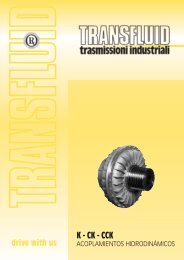
K - CK - CCK - Transfluid
K - CK - CCK - Transfluid
K - CK - CCK - Transfluid

You also want an ePaper? Increase the reach of your titles
YUMPU automatically turns print PDFs into web optimized ePapers that Google loves.
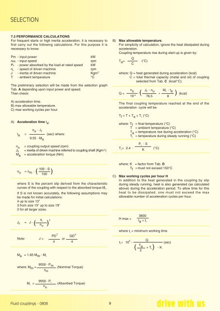
SELECTION<br />
7.3 PERFORMANCE CALCULATIONS<br />
For frequent starts or high inertia acceleration, it is necessary to<br />
first carry out the following calculations. For this purpose it is<br />
necessary to know:<br />
Pm - input power<br />
kW<br />
nm - input speed<br />
rpm<br />
PL - power absorbed by the load at rated speed kW<br />
n L - speed of driven machine rpm<br />
J - inertia of driven machine Kgm<br />
T - ambient temperature °C<br />
The preliminary selection will be made from the selection graph<br />
Tab. A depending upon input power and speed.<br />
Then check:<br />
A) acceleration time.<br />
B) max allowable temperature.<br />
C) max working cycles per hour<br />
A) Acceleration time t a :<br />
n u<br />
• Jr<br />
t a = (sec) where:<br />
9.55 • M a<br />
n u = coupling output speed (rpm)<br />
J r = inertia of driven machine referred to coupling shaft (Kgm 2 )<br />
M a = acceleration torque (Nm)<br />
n u = n m<br />
•<br />
(<br />
100 - S<br />
)<br />
where S is the percent slip derived from the characteristic<br />
curves of the coupling with respect to the absorbed torque M L .<br />
If S is not known accurately, the following assumptions may<br />
be made for initial calculations:<br />
4 up to size 13”<br />
3 from size 15” up to size 19”<br />
2 for all larger sizes.<br />
J r = J • (<br />
n L<br />
100<br />
)<br />
n u<br />
2<br />
2 2<br />
PD GD<br />
Note: J = or<br />
4 4<br />
2<br />
B) Max allowable temperature.<br />
For simplicity of calculation, ignore the heat dissipated during<br />
acceleration.<br />
Coupling temperature rise during start-up is given by:<br />
T a =<br />
Q<br />
C<br />
(°C)<br />
where: Q = heat generated during acceleration (kcal)<br />
C = total thermal capacity (metal and oil) of coupling<br />
selected from Tab. C (kcal/°C).<br />
n u<br />
10<br />
Q = ( + ) (kcal)<br />
The final coupling temperature reached at the end of the<br />
acceleration cycle will be:<br />
T f = T + T a + T L (°C)<br />
4<br />
•<br />
J r<br />
• nu<br />
76.5<br />
where: T f = final temperature (°C)<br />
T = ambient temperature (°C)<br />
T a = temperature rise during acceleration (°C)<br />
T L = temperature during steady running (°C)<br />
P • L S<br />
T L = 2.4 • K<br />
(°C)<br />
where: K = factor from Tab. D<br />
T f = must not exceed 150°C<br />
C) Max working cycles per hour H<br />
In addition to the heat generated in the coupling by slip<br />
during steady running, heat is also generated (as calculated<br />
above) during the acceleration period. To allow time for this<br />
heat to be dissipated, one must not exceed the max<br />
allowable number of acceleration cycles per hour.<br />
M L<br />
• ta<br />
3600<br />
H max =<br />
t a + t L<br />
where t L = minimum working time<br />
3 Q<br />
t L = 10 • (sec)<br />
T<br />
( a + T • L ) K<br />
2<br />
8<br />
M a = 1.65 M m - M L<br />
where: M m =<br />
9550 • P m<br />
n m<br />
(Nominal Torque)<br />
9550<br />
dove: M L = • P L<br />
(Absorbed Torque)<br />
n u<br />
Fluid couplings - 0808<br />
9