SAILOR SYSTEM 5000 MF/HF 150/250W
SAILOR SYSTEM 5000 MF/HF 150/250W
SAILOR SYSTEM 5000 MF/HF 150/250W

Create successful ePaper yourself
Turn your PDF publications into a flip-book with our unique Google optimized e-Paper software.
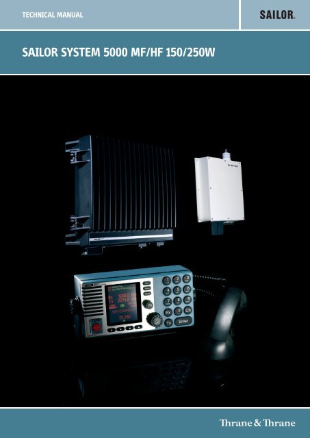
TECHNICAL MANUAL<br />
<strong>SAILOR</strong> <strong>SYSTEM</strong> <strong>5000</strong> <strong>MF</strong>/<strong>HF</strong> <strong>150</strong>/<strong>250W</strong>
Disclaimer<br />
Any responsibility or liability for loss or damage in connection with the use of this product and the accompanying<br />
documentation is disclaimed by Thrane & Thrane. The information in this manual is provided for information<br />
purposes only, is subject to change without notice, may contain errors or inaccuracies, and represents no commitment<br />
whatsoever by Thrane & Thrane. This agreement is governed by the laws of Denmark.<br />
Manuals issued by Thrane & Thrane are periodically revised and updated. Anyone relying on this information<br />
should satisfy himself/herself as to the most current version. Providers with access to Thrane & Thrane’s Extranet<br />
may obtain current copies of manuals at: http://extranet.thrane.com.<br />
Thrane & Thrane is not responsible for the content or accuracy of any translations or reproductions, in whole or<br />
in part, of this manual from any other source.
<strong>MF</strong>/<strong>HF</strong> <strong>150</strong>W/<strong>250W</strong><br />
CONTENTS<br />
0715<br />
1 General information 1-1<br />
1.1 Introduction 1-1<br />
1.2 Technical data 1-1<br />
2 Installation 2-1<br />
2.1 Description 2-1<br />
2.2 Mounting the units 2-1<br />
2.3 Ground connections 2-6<br />
2.4 Grounding considerations 2-6<br />
2.5 Antennas 2-8<br />
2.6 Power supply 2-11<br />
2.7 Interconnection of units 2-12<br />
2.8 Connector mounting instructions 2-19<br />
2.9 Position and time information 2-20<br />
2.10 DSC programming 2-20<br />
2.11 Battery alarm adjustment 2-21<br />
2.12 Options menu - setting up the system 2-21<br />
2.13 Factory resetting / MMSI resetting 2-23<br />
2.14 Enabling the 6 ch scanning DSC Watch Receiver 2-23<br />
2.15 Enabling the Telex operation 2-24<br />
2.16 Telex operation 2-24<br />
2.17 Final installation check 2-26<br />
3 Technical description 3-1<br />
3.1 Control Unit 3-1<br />
3.2 Transceiver Unit 3-1<br />
3.3 Control/Intercon module 60-122878 3-1<br />
3.4 Synth. and DSC WR module 60-122879 3-1<br />
3.5 RX/EX signal path module 60-122880 3-2<br />
3.6 PA and Filters module 60-122881 3-2<br />
3.7 SMPS module 60-122882 3-2<br />
3.8 Transceiver unit block diagram 3-3<br />
3.9 Transceiver unit interconnection diagram 3-4<br />
3.10 Antenna Tuning Unit 3-5<br />
3.11 Antenna Tuning Unit block diagram 3-5<br />
3.12 Power control and protection system 3-6<br />
3.13 Power control and protection system 3-7<br />
4 Service 4-1<br />
4.1 Preventive maintenance 4-1<br />
4.2 Realignment of master oscillator 4-1<br />
4.3 Software update 4-2<br />
4.4 Trouble shooting 4-2<br />
4.5 Power protection 4-3<br />
4.6 Selftest 4-5<br />
5 Spare part exchange 5-1<br />
5.1 Disassembling the Transceiver Unit 5-1<br />
5.2 Transceiver Unit module location 5-2<br />
5.3 Required service tool 5-4<br />
5.4 Accessory list 5-4
<strong>MF</strong>/<strong>HF</strong> <strong>150</strong>W/<strong>250W</strong><br />
1 General information<br />
1.1 Introduction<br />
The <strong>150</strong>W / <strong>250W</strong> <strong>MF</strong>/<strong>HF</strong> transceiver with integrated DSC and telex is designed for maritime applications<br />
in voluntary as well as compulsorily fitted vessels. It offers simplex and semi-duplex SSB radiotelephone<br />
communication in the maritime mobile frequency bands between 1.6 and 30 MHz. The basic version of<br />
the transceiver include voice, DSC and a dedicated 2187,5kHz DSC watch receiver, forming an ideal<br />
system for <strong>MF</strong> GMDSS installations. The transceiver can easily be upgraded to include 6 channel<br />
scanning DSC watch receiver, and Telex operation to comply with <strong>MF</strong>/<strong>HF</strong> requirements in sea area A3.<br />
The upgrade is done by entering software license codes.<br />
The equipment consists of a compact transceiver control unit, a fully remote controlled transceiver unit<br />
and an automatic antenna tuning unit.<br />
The microprocessor controlled Antenna Tuning Unit automatically matches the impedance of antennas<br />
between 8 and 18 metres in length and requires no presetting at the installation. The typical tuning time<br />
is 1 s. It is designed for outdoor installation and may be located up to 100 metres from the Transceiver<br />
Unit.<br />
The Transceiver Unit contains all receiver and transmitter circuits. The fully protected solid state <strong>150</strong>W<br />
/ <strong>250W</strong> power amplifier cooled by natural convection matches a 50 ohm antenna system, but is normally<br />
used in connection with the Antenna Tuning Unit. The DSC/Telex modem contains two demodulators,<br />
one connected to the built-in watch receiver for continuous watch on the DSC distress frequency 2187.5<br />
kHz, the other connected to the communication receiver which may be used to keep simultaneous watch<br />
on other DSC frequencies or may be used for telex communication.<br />
The Control Unit is for operation of radiotelephone as well as DSC and telex functions. Use of the<br />
equipment is simple, logic and straight forward. DSC operation is based on the use of soft keys. Guiding<br />
texts are provided and the large display is able to show the contents of a complete call in one screen.<br />
For telex operation the keyboard, printer or data terminal can be connected directly to the control unit.<br />
The equipment is designed for operation from a 24 V battery. With the optional AC Power Supply unit<br />
installed the equipment may be supplied from 115/230 V AC main or emergency supplies with automatic<br />
switch-over to 24 V DC supply in the absence of AC supply voltage. Also optionally battery charger for<br />
AC is available in the product line.<br />
The built-in test facilities and easy-to-replace module design of the equipment simplifies the service<br />
concept.<br />
1.2 Technical data<br />
1.2.1 General<br />
Complies with the relevant IMO performance standards for <strong>MF</strong>/<strong>HF</strong> GMDSS equipment, the ITU Radio<br />
Regulations, the ITU-R recommendations and the relevant performance specifications of ETSI and IEC,<br />
in the ITU marine bands.<br />
Operating modes:<br />
Frequency range:<br />
Frequency stability:<br />
Normal operating<br />
temperature:<br />
Extreme operating<br />
temperature:<br />
Simplex and semi-duplex SSB telephony (J3E), DSC (J2B), AM broadcast<br />
reception (A3E) and Telex (J2B).<br />
Refer to sections concerning specific characteristics.<br />
better than 0.35ppm<br />
Warm-up time. Less than one minute.<br />
Ageing less than 0,1ppm/year.<br />
from 0°C to +40°C.<br />
from -15°C to +55°C<br />
User-programmable<br />
channels: 199 frequency pairs with mode (1-199)<br />
0812<br />
User-programmable<br />
stations:<br />
40 stations with name, MMSI and station channel<br />
1-1
1 General information <strong>MF</strong>/<strong>HF</strong> <strong>150</strong>W/<strong>250W</strong><br />
Output power:<br />
Refer to sections concerning Receiver / Transmitter characteristics<br />
Supply voltage: Nominal 24V DC floating (-10 +30%)<br />
With optional external AC power supply:<br />
115/230V AC 50/60 Hz. Automatic change-over to DC in the absence of<br />
AC supply<br />
Power consumption: <strong>150</strong>W: <strong>250W</strong>:<br />
Rx, 60W (approx. at 24V DC)<br />
Tx, SSB speech: 175W 300W<br />
Tx, SSB two-tone: 300W 550W<br />
Tx, DSC/TELEX: 420W 600W<br />
Compass safe distance:<br />
Compass safe distance in accordance with ISO/R 694 are given below<br />
in metres.<br />
Unit Standard Steering<br />
5.4°/H 18°/H<br />
Control Unit 1.2 0.5<br />
Transceiver Unit 0.4 0.2<br />
Antenna Tuning Unit 0.3 0.1<br />
Handset 0.3 0.2<br />
Cradle 1.1 0.7<br />
5070 Loudspeaker 2.2 1.6<br />
1.2.2 Receiver characteristics<br />
General:<br />
Complies with ETSI 300373 in the ITU marine bands.<br />
Reception: Mode Rx/Tx antenna plug DSC/Telex antenna plug<br />
SSB/AM X<br />
DSC<br />
X<br />
Telex<br />
X<br />
Frequency range:<br />
Frequency resolution:<br />
<strong>150</strong> kHz to 30 MHz.<br />
100 Hz by keyboard entry.<br />
10 Hz, 100 Hz or 1 kHz search/fine-tune facility is provided.<br />
Input impedance: Rx/Tx : 50 ohm<br />
The Antenna is matched by the antenna amplifier in the Aerial Coupler.<br />
DSC/Telex:<br />
50 ohm<br />
12V DC / 20 mA is available for eventual use of active antenna.<br />
Sensitivity: Telephony(J3E): below 11 dBµV for 20 dB Sinad<br />
Broadcast (A3E):<br />
below 25 dBµV for 20 dB Sinad<br />
DSC/Telex (J2B):<br />
below 0 dBµV<br />
Intermodulation: Telephony (J3E): Wanted Signal: 30 dBµV<br />
Intermodulation level:<br />
above 80 dBµV<br />
Telex(J2B): Wanted Signal: 30 dBµV<br />
Intermodulation level:<br />
above 90 dBµV<br />
DSC (J2B): Wanted Signal: 20 dBµV<br />
Intermodulation level:<br />
above 80 dBµV<br />
Spurious rejection:<br />
above 70 dB<br />
Audio output power:<br />
Build-in loudspeaker<br />
Optional loudspeaker output 4 W typical with less than 10 % distortion.<br />
Output intended for 8 ohm loudspeaker.<br />
1-2<br />
0812
1 General information <strong>MF</strong>/<strong>HF</strong> <strong>150</strong>W/<strong>250W</strong><br />
1.2.3 Transmitter characteristics<br />
General:<br />
Frequency range:<br />
Frequency resolution:<br />
Output power:<br />
Complies with ETSI 300373 or better in the ITU marine bands.<br />
The Transmitter characteristics are with the Aerial Coupler included.<br />
The ITU marine bands in the frequency range 1605 kHz to 30 MHz<br />
100 Hz.<br />
<strong>150</strong>W SSB:<br />
± 1.4 dB into 50 ohm Antenna, voice for a duty cycle less than 55% and<br />
modulation rate greater than 3 baud.<br />
Reduction to 80W when continuously keyed with duty cycle greater than<br />
55% during 1 min. Automatic power recovery after 1 min.<br />
DSC/Telex:<br />
85W ± 1.4 dB<br />
<strong>250W</strong> SSB:<br />
±1.4 dB into 50 ohm Antenna, voice for a duty cycle less than 55% and<br />
modulation rate greater than 3 baud.<br />
Reduction to 100W when continuously keyed with duty cycle grater than<br />
55% during 1 min. Automatic power recovery after 1 min.<br />
DSC/Telex:<br />
125W ± 1.4 dB<br />
Power reduction: Low power: approx. 20 W PEP.<br />
Intermodulation:<br />
Spurious Emission:<br />
Hum and noise:<br />
below -31 dB/PEP.<br />
below -43 dB/PEP.<br />
Less than - 40 dB/PEP.<br />
1.2.4 DSC Watch receiver characteristics<br />
General:<br />
Reception:<br />
Frequency range:<br />
Complies with ETSI 300338 or better.<br />
DSC/Telex antenna plug.<br />
Scanning the following frequencies:<br />
2187,5 KHz, 4207,5 kHz, 6312,0 KHz, 8414,5 kHz, 12577,0 KHz,<br />
16814,5 kHz.<br />
Input impedance: DSC/Telex: 50 ohm.<br />
12V DC / 20 mA is available for eventual use of active antenna.<br />
Sensitivity: DSC (J2B): below 0 dBµV.<br />
Intermodulation: DSC (J2B): Wanted Signal: 20 dBµV.<br />
Intermod. level: above 70 dBµV.<br />
Spurious rejection:<br />
above 70 dB.<br />
0812<br />
1-3
1 General information <strong>MF</strong>/<strong>HF</strong> <strong>150</strong>W/<strong>250W</strong><br />
1.2.5 Aerial coupler characteristics<br />
General:<br />
Frequency range:<br />
Aerial requirements:<br />
Aerial tuning:<br />
Tuning speed:<br />
Power capability:<br />
Extreme operating<br />
temperature:<br />
Complies with ETSI 300373 or better in the ITU marine bands.<br />
1.6 MHz - 27 MHz.<br />
8-18 m wire and/or whip aerial.<br />
Fully automatic with no presetting.<br />
0.1 - 8 sec.<br />
350W PEP into 50 ohm Antenna.<br />
from -25°C to +55°C.<br />
1.2.6 DSC/Telex modem characteristics<br />
DSC: DSC Equipment class: Class A.<br />
Protocols: ITU-R M. 493.12, M. 541-6, and M. 1082.<br />
Ship’s identity:<br />
9-digit identity number.<br />
Navigator interface: According to IEC 61162-1<br />
GLL, RMC, ZDA, GGA.<br />
TELEX: Protocols: ITU-R M. 625-2 (incl. M. 476-4), M. 490,<br />
M. 491-1, and 492-5 NBDP telex in ARQ, FEC<br />
and SELFEC modes.<br />
Ship’s identity:<br />
5- and/or 9-digit identity number.<br />
1.2.7 Dimensions and weight<br />
Control Unit:<br />
CU5100/CU5110: Width: 200 mm (7,9")<br />
Height: 100 mm (3,9")<br />
Depth: 80 mm (3.1")<br />
Weight: 3.3 kg (7.3 lbs)<br />
Transceiver Unit<br />
TU5<strong>150</strong>/TU5155/TU5250: Width: 390 mm (15.3")<br />
Height: 445 mm (17.5")<br />
Depth: 127 mm (5")<br />
Weight: 19 kg (41.9 lbs)<br />
Antenna Tuning Unit:<br />
ATU5215: Width: 290 mm (11.4")<br />
Height: 500 mm (19.7")<br />
Depth: 80 mm (3.1")<br />
Weight: 3.3 kg (7.3 lbs)<br />
Equipment category: Control Unit: Protected,<br />
Transceiver Unit: Protected,<br />
Antenna Tuning Unit: Exposed.<br />
1-4<br />
0715
<strong>MF</strong>/<strong>HF</strong> <strong>150</strong>W/<strong>250W</strong><br />
2 Installation<br />
2.1 Description<br />
Correct installation of the equipment is important for maximum performance and reliability. Antennas and<br />
earth connections must be installed with the greatest care using corrosion resistant materials.<br />
Cable routing shall be made so the cables are protected from physical damage. Sharp cable bends<br />
especially on coaxial cables must be avoided and a sufficient number of clips or straps should be used<br />
to secure the cables.<br />
2.2 Mounting the units<br />
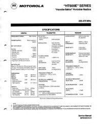
Mounting the Control Unit (CU)<br />
One Unit shall be connected to the Transceiver Unit using the build-in local area network (ScanBus). The<br />
CU may be mounted up to 100m from the Transceiver Unit using just one Multicable 5 x 2 x 0.5 mm 2<br />
screened.<br />
The Control Unit may be tabletop or bulkhead mounted.<br />
Control Units with mounting bracket<br />
140<br />
100<br />
40536A<br />
200<br />
235<br />
100<br />
Mounting option<br />
Drilling plan<br />
4 x ø4<br />
Tilting +/-45 °<br />
7.00<br />
55.00<br />
41.00<br />
14.50<br />
181.00<br />
209.00<br />
Control unit connector panel<br />
40615<br />
Handset AUX SCAN-BUS<br />
Keyboard Data Printer<br />
40616<br />
0812<br />
Weight:<br />
Control Unit 1.4 kg.<br />
Mounting Bracket 0.3 kg.<br />
2-1
2 Installation <strong>MF</strong>/<strong>HF</strong> <strong>150</strong>W/<strong>250W</strong><br />
Control Units with flush mounting bracket<br />
Bracket (Option)<br />
120<br />
99-127233<br />
240<br />
min. 100.00<br />
Space for Cable entry<br />
3<br />
Drilling plan<br />
6 108<br />
20<br />
20<br />
4 pcs. ø5<br />
4 pcs. ø3.5<br />
countersunk for M3<br />
102 9<br />
219 10<br />
20 20<br />
228 6<br />
4 pcs M3x30<br />
99-127234<br />
4 pcs M4x12<br />
4 pcs M4x30<br />
Weight:<br />
Mounting kit<br />
(Part no. 405100-920)<br />
0.5 kg<br />
WARNING:<br />
Only use screws supplied with<br />
mounting kit for attaching flush<br />
mounting bracket to Control Unit.<br />
Handset for Control Unit<br />
Drilling plan<br />
135<br />
226<br />
45<br />
39655B<br />
62<br />
This Handset has a hook-on/off function,<br />
which is activated by a small magnet embedded<br />
in the ceadle.<br />
The cradle must be installed as illustrated in<br />
order to ensure the hook-on/off functionality<br />
of the Handset.<br />
75<br />
min. 200<br />
Space for cable and handset cable<br />
54<br />
* 120<br />
Space for handset access<br />
Weight:<br />
Handset for Control Unit 0.4 kg<br />
Dimensions are in mm<br />
2-2<br />
0812
2 Installation <strong>MF</strong>/<strong>HF</strong> <strong>150</strong>W/<strong>250W</strong><br />
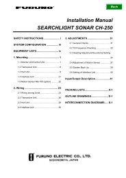
Mounting the Transceiver Unit (TU)<br />
The Transceiver Unit should be installed in a dry place and consideration should be given to accessibility<br />
for servicing. It is important to provide sufficient airspace below, above and in front of the unit for adequate<br />
air circulation through the cooling fins. The drawing below shows the outer dimensions, mounting<br />
possibilities and the minimum distance to other objects, as well as a drilling plan.<br />
391<br />
145<br />
88<br />
2<br />
350<br />
430<br />
1<br />
4 x ø8<br />
Cable fitting<br />
1<br />
37955A<br />
360<br />
1) Space for cable: min. <strong>150</strong> mm<br />
2) Space for airflow and service: min. 500 mm<br />
Cable fitting<br />
57.6<br />
70<br />
56<br />
12<br />
80<br />
38417<br />
Dimensions are in mm<br />
0715<br />
2-3
2 Installation <strong>MF</strong>/<strong>HF</strong> <strong>150</strong>W/<strong>250W</strong><br />
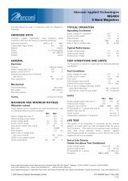
Mounting the Antenna Tuning Unit (ATU)<br />
The Antenna Tuning Unit may be mounted up to 100 metres from the Transceiver Unit using just one RG-<br />
213/U coaxial cable. The unit should be installed near the antenna feed point.<br />
76.5<br />
145<br />
75<br />
12 164 164<br />
170<br />
80<br />
290<br />
200<br />
1)<br />
6 x ø6.50<br />
2)<br />
352<br />
3)<br />
271<br />
50<br />
37978<br />
1) Space to nearest overhang: min. 50 mm<br />
2) Space for service access: min. 500 mm<br />
3) Space for cable and service access: min. 200 mm<br />
Dimensions are in mm<br />
2-4<br />
0715
2 Installation <strong>MF</strong>/<strong>HF</strong> <strong>150</strong>W/<strong>250W</strong><br />
CB4616 Terminal Block Converter Box (accessory)<br />
CB4616 is used to convert the rather small DSUB-9 to a screw terminal with strain relief for large cables<br />
such as veritas cables. This box is delivered with a 1m DSUB-DSUB cable for connection to CU or TU.<br />
Drilling Plan<br />
12<br />
67.25<br />
45.5<br />
4 x ø4.7mm<br />
104.5<br />
196<br />
9.7<br />
176.6<br />
38419<br />
Weight:<br />
CB4616<br />
0.6 kg.<br />
CB4618 Handset Connection Box (accessory)<br />
CB4618 is used to connect the scrambler CRY2001 or to interface a secondary handset or the Heavy Duty<br />
Handset.<br />
Drilling Plan<br />
X1 (Control Unit) X2 (1. Handset) X3 (2. Handset/CRY)<br />
12<br />
67.25<br />
45.5<br />
4 x ø4.7mm<br />
104.5<br />
196<br />
9.7<br />
176.6<br />
38387<br />
Weight:<br />
CB4618<br />
0.6 kg.<br />
Dimensions are in mm<br />
CB4616 and CB4618 may be ordered as accessory. Please find accessory list on the last page of this<br />
manual.<br />
0715<br />
2-5
2 Installation <strong>MF</strong>/<strong>HF</strong> <strong>150</strong>W/<strong>250W</strong><br />
2.3 Ground connections<br />
Antenna Tuning Unit<br />
As the earth connection of a transmitter is a very important<br />
part of the antenna system, it is of the utmost importance<br />
to keep in mind that the earth connection of the Antenna<br />
Tuning Unit must have the lowest possible RF-impedance.<br />
Losses in the earth connection will result in a decrease in<br />
radiated power which means that the range of the<br />
transmitter will be reduced. In steel ships a 100 x 0.5 mm<br />
copper strap as short as possible is connected between<br />
Copper strap 100 x 0.5mm<br />
the earth terminal at the bottom of the Antenna Tuning<br />
R3.3<br />
Unit and two or three 1/2" or M12 bolts welded to the<br />
superstructure. Vessels constructed of non-conducting<br />
materials must be equipped with a copper earth plate<br />
having a minimum area of 1 square metre mounted below<br />
the water line. From a copper earth bolt hard soldered to<br />
the earth plate a 100 x 0.5 mm copper strap is run,<br />
6<br />
Dimensions are in mm.<br />
37872<br />
preferably uninterrupted to the earth terminal at the bottom<br />
of the Antenna Tuning Unit.<br />
Should it be necessary to break the copper strap, for example to pass through a deck, two or three 1/2"<br />
or M12 bolts should be used for this feed through. On wooden ships having a superstructure of metal,<br />
this superstructure should also be effectively connected to the copper strap by using stainless steel bolts<br />
and preferably pieces of stainless steel strips between the metal parts. On fibre glass boats, such as<br />
yachts and sailing boats, it may be difficult to install a sufficiently good earth. Short copper straps are<br />
bolted to conducting parts on the engine, the keel and other conducting objects. Many copper straps can<br />
be glued to the inner surface of the hull below the water line to produce a large capacitance to the water.<br />
It is important that the total area of copper is large and that the distance between the copper surface and<br />
the water is as small as possible. The copper straps are connected directly to the ATU.<br />
80<br />
50<br />
20<br />
6.6<br />
Transceiver Unit and Control Unit<br />
The Transceiver Unit is preferably grounded<br />
separately to the ships metal in the shortest possible<br />
way. A 10 to 16mm sq. ground wire is connected to<br />
the ground terminal (cable clamp) at the bottom of<br />
the unit.<br />
37836<br />
11mm<br />
ø5.4mm<br />
crimp<br />
wire<br />
2.4 Grounding considerations<br />
Proper system grounding is one of the most important installation details.<br />
Two areas of grounding must be considered:<br />
a) The ground connection between the ATU and earth ground plane.<br />
b) The ground connection of the TU and the externally connected equipment.<br />
Each area requires separate considerations<br />
even though they are interrelated. Ideally the<br />
Control Unit, Transceiver Unit, Antenna Tuning<br />
Unit and the antenna ground-plane must<br />
have the same RF ground potential. Unfortunately<br />
this situation is seldom achieved, but<br />
interference problems will be reduced along<br />
with how close to this “ideal” the grounding of<br />
the installation is performed.<br />
On some installations ground loops will cause<br />
problems. A ground loop is caused by more<br />
than one ground path for a given unit. This will<br />
introduce circulating RF currents which may<br />
cause malfunction of other equipment onboard<br />
the ship as well as a “hot” handset.<br />
37867<br />
ATU<br />
Zg<br />
Not OK installation<br />
TU<br />
RF current loop<br />
Ground-Plane<br />
CU<br />
'Hot' Handset<br />
2-6<br />
0715
2 Installation <strong>MF</strong>/<strong>HF</strong> <strong>150</strong>W/<strong>250W</strong><br />
Antenna start<br />
The vertical antenna always start at its electrical ground-plane, whether or not it is physically mounted<br />
there. First determine the antenna’s electrical ground-plane, which is where the ATU must be mounted.<br />
Where possible always take the ATU to the ground, not the ground to the ATU.<br />
In case of a fibreglass boat, the ground-plane may well be at the hull grounding terminal. Then this is where<br />
the Antenna Tuning Unit should go and this is where the antenna actually starts.<br />
OK installation<br />
Not a 'Hot' Handset<br />
TU<br />
CU<br />
ATU<br />
Ground-Plane<br />
37868<br />
The antenna starts here<br />
RF ground loop<br />
It is not always possible or practical to mount the ATU using a very short strap to the actual ground-plane.<br />
In such a case the coaxialcable may be connected between units with different ground potentials causing<br />
RF loop-current to flow.<br />
Not OK installation<br />
ATU<br />
TU<br />
CU<br />
Vg = Iant x Zg<br />
coaxial cable<br />
Zg<br />
RF current loop<br />
Ground-Plane<br />
37869<br />
Minimizing ground loops<br />
By routing the coax cable very close together with the ATU ground strap (secure good RF coupling<br />
between the two) all the way down to the ground-plane, there will be no RF ground loop left to generate<br />
the interference.<br />
OK installation<br />
ATU<br />
TU<br />
CU<br />
Vg = Iant x Zg<br />
Zg<br />
coaxial cable<br />
Ground-Plane<br />
0715<br />
37870<br />
2-7
2 Installation <strong>MF</strong>/<strong>HF</strong> <strong>150</strong>W/<strong>250W</strong><br />
2.5 Antennas<br />
Transceiver Antenna<br />
The equipment is used with common transmitting and receiving antenna. The antenna should be erected<br />
in the open, away from conducting object such as derricks etc. which may cause reduction of the radiated<br />
power. Insulators should be of the best type having low leakage even when wet. Stays, wires, steel masts<br />
etc. should be either effectively earthed or insulated. The antenna should also be kept as far away as<br />
possible from electrical equipment in order to minimize noise. Electrical installation such as cable braiding<br />
(screens) and instruments in the vicinity of the antenna should be earthed effectively, and the instruments<br />
in question should be fitted with noise-interference suppression devices, effective in the range 0.1 MHz<br />
to 30 MHz to avoid malfunction of these instruments. The Antenna Tuning Unit will tune on any frequency<br />
in the range 1.6 to 27 MHz to good whip and/or wire installations of 12 to 18 meters total electrical length.<br />
Shorter antennas, electrical length down to 8 meters can be used. Where possible long antennas should<br />
be installed to maximize the radiated power in the lower frequency bands.<br />
In general a 12 meter antenna installation can be made using an 8 meter whip and 4.5 meter feeder or<br />
a 10 meter whip and 2.5 meter feeder. In both cases the whip should be mounted on a pole allowing for<br />
the feeder to be erected at an angle of no less than 60 degrees to create a vertical antenna system. Using<br />
horizontal feeders or feeders mounted at an angle below 45 degrees usually transform the antenna<br />
radiation resistance to a lower value reducing the radiated power. Furthermore, the total antenna system<br />
should be kept well away from conductive objects such as the mast. Usually a horizontal distance of more<br />
than 4 meters will create good results.<br />
Note: If a whip antenna is used this should have an anti-corona ball as a top termination to prevent<br />
crackling noise in the receiver.<br />
The antenna is terminated at the insulator at the top of the<br />
Antenna Tuning Unit. The insulator must be relieved from<br />
mechanical stress by using max. 1 metre flexible wire<br />
between the insulator and a support. To maximize the<br />
radiated power and avoid flash over keep distance to metal<br />
parts as long as possible. All wire junctions in the antenna<br />
system must be made with cable lugs of correct size<br />
according to the wire gauge. This will prevent bad connections<br />
due to corrosion. For further corrosion proofing grease<br />
may be applied to the cable joints.<br />
2-8<br />
0715
2 Installation <strong>MF</strong>/<strong>HF</strong> <strong>150</strong>W/<strong>250W</strong><br />
Recommended ATU installation<br />
On a metal-hull vessel. Mount the Antenna Tuning Unit on a custom-built bracket made from iron angle<br />
bars (refer to figure on previous page).<br />
Antenna Tuning Unit bracket<br />
welded to the railing.<br />
Antenna Tuning Unit bracket<br />
welded to the deck.<br />
0715<br />
2-9
2 Installation <strong>MF</strong>/<strong>HF</strong> <strong>150</strong>W/<strong>250W</strong><br />
Optional an ATU Mounting Kit may be supplied as shown below. The kit exists in two versions:<br />
1 Includes mounting plate and fittings for mast. Part no. 737589<br />
2 Includes the mounting plate. Part no. 737588<br />
1 For mounting the ATU directly on a mast, where the Mounting Plate and fittings for mast can form<br />
a sufficient earth connection on a steel mast welded to the superstructure.<br />
2 To get an even mounting surface on an uneven support.<br />
1 2 3 4 5<br />
6 x mountingholes for Antenna Tuner Unit.<br />
5 Treadrod M10 64.005<br />
4 Mountingplate 237218<br />
1 Nut M10<br />
2 Tooth lock washer M10<br />
3 Fitting for mast<br />
4 Mountingplate for ATU<br />
5 Treadrod M10<br />
DSC watch receiver antenna<br />
The DSC watch receiver antenna may be an active or a passive type.<br />
The antenna should be erected well in the clear and kept away as far as possible from electrical<br />
equipment in order to minimize noise. Electrical installation such as cable braiding and instruments in the<br />
vicinity of the antenna should be earthed effectively, and the instruments in question should be fitted with<br />
noise-interference suppression devices, effective in the range 0.1 to 30 MHz. The antenna feed-in should<br />
be coaxial cable.<br />
In case of a passive antenna the feed-in should be as short as possible, especially in the case of short<br />
antennas. The recommended antenna length is 7-30 meters. If a long coax cable is necessary an<br />
impedance matching transformer should be inserted at the antenna or an active antenna should be used.<br />
DC supply voltage for an active antenna is available at the DSC RX antenna connector. The supply<br />
voltage is +12 V for supply currents up to 20 mA. The short circuit current is limited to 2 mA to allow passive<br />
antennas with matching transformers to be connected directly.<br />
2-10<br />
0715
2 Installation <strong>MF</strong>/<strong>HF</strong> <strong>150</strong>W/<strong>250W</strong><br />
2.6 Power supply<br />
The supply leads are connected to the supply terminal strip of the Transceiver Unit. The supply terminal<br />
strip is adapted for screened power supply cable to meet EMC requirements. The screen of the cable is<br />
connected to the left terminal.<br />
The earth connection of the equipment will not cause the battery to be earthed. Maximum permissible<br />
peak voltage between the battery terminals and earth is 100 V. Note that fuses must be provided in the<br />
supply leads. Table below shows the necessary cable cross sections and external fuse ratings.<br />
60mm<br />
15mm<br />
screen (twisted)<br />
plastic cover<br />
conductor (twisted)<br />
screw<br />
clamp<br />
cable fitting<br />
plastic house<br />
37835<br />
Max. cable length to Recommended cable External fuses<br />
battery * Screened multiwire<br />
5 m 2 x 10 mm2 40 A<br />
8 m 2 x 16 mm2 50 A<br />
12 m 2 x 25 mm2 63 A<br />
0715<br />
2-11
2 Installation <strong>MF</strong>/<strong>HF</strong> <strong>150</strong>W/<strong>250W</strong><br />
2.7 Interconnection of units<br />
Transceiver Unit connector panel<br />
-<br />
+<br />
SCANBUS<br />
SYS<br />
SUPPLY ALARM<br />
DSC RX<br />
RX/TX<br />
1 1<br />
1<br />
24 V DC<br />
37849<br />
Control Unit connector panel<br />
Handset AUX SCAN-BUS<br />
Keyboard Data Printer<br />
40616<br />
Antenna Tuning Unit connector panel<br />
40631<br />
2-12<br />
0715
2 Installation <strong>MF</strong>/<strong>HF</strong> <strong>150</strong>W/<strong>250W</strong><br />
40669A<br />
Handset Control Unit Transceiver Unit<br />
1<br />
Handset AUX SCANBUS Keyboard Data Printer GND<br />
SCANBUS 24 V DC<br />
Dsub<br />
9<br />
male<br />
* ) * )<br />
* ) )<br />
Dsub<br />
9<br />
male<br />
Dsub<br />
9<br />
male<br />
PS2<br />
Dsub<br />
9<br />
male<br />
Dsub<br />
25<br />
male<br />
SUPPLY<br />
ALARM<br />
SYS RX/TX DSC RX RX/TX<br />
Antenna<br />
Tuning<br />
Unit<br />
2 5 7<br />
Dsub<br />
Dsub<br />
Dsub<br />
PL259 PL259<br />
9<br />
male<br />
* * )<br />
9<br />
male<br />
9<br />
male<br />
RG-213/U<br />
6<br />
3 4<br />
Option<br />
13<br />
14<br />
12<br />
5 x 2 x 0.5 mm2<br />
15<br />
16<br />
17<br />
18<br />
RG-213/U<br />
Note:<br />
In Telex Mode the Communication Receiver<br />
uses the Watch Receiver Antenna.<br />
***<br />
Loud<br />
speaker<br />
8<br />
)<br />
GPS<br />
2 x 0.5 mm2<br />
8<br />
2 x 0.5 mm2<br />
9<br />
Option 1<br />
Either option 1<br />
or option 2<br />
Data<br />
Terminal<br />
Option 2<br />
Data<br />
Modem<br />
etc.<br />
(optional)<br />
Distress<br />
Alarm<br />
Panel<br />
(optional)<br />
4x 0.5 mm2<br />
10<br />
Printer<br />
Printer<br />
4 x 0.5 mm2<br />
15<br />
TX<br />
inhibit<br />
(optional)<br />
External<br />
DSC<br />
Alarms<br />
(optional)<br />
4 x 0.5 mm2<br />
11<br />
Keyboard<br />
Keyboard<br />
** ) **<br />
)<br />
AC<br />
Power<br />
Supply<br />
(optional)<br />
24 V<br />
Battery<br />
Battery<br />
Charger<br />
*<br />
) Please check the accessory list to find the optional DSUB to screw Terminal Converter Box CB4616.<br />
) Please check the accessory list to find recommended power products.<br />
**<br />
***<br />
) Please check the accessory list to find recommended loudspeaker.<br />
Please note that for distance less than 25m the system will work with 0.25mm² instead of 0.5mm².<br />
0812<br />
2-13
2 Installation <strong>MF</strong>/<strong>HF</strong> <strong>150</strong>W/<strong>250W</strong><br />
Cable 1: Handset - Control Unit<br />
Cable: Supplied with handset<br />
Cable-connector: 9 way Dsub male.<br />
Control Unit<br />
‘HANDSET’ Designation Remarks<br />
Dsub 9<br />
1 TLF Handset earpiece<br />
2 GND System ground<br />
3 GND System ground<br />
4 MIC Handset microphone<br />
5 PTT Transmit key<br />
6 HOOK Low when on hook<br />
7 +8V 8 V supply to handset<br />
8 nc No connection<br />
9 2182 SEL OC output. Low when 2182 kHz is<br />
selected<br />
Cable 2: Control Unit - Ground<br />
Recommended wire dimension: min. 2.5 mm 2<br />
Maximum length 0.2 m<br />
Cable 3: Control Unit - Transceiver Unit<br />
Cable: Multicable 5 x 2 x 0.5 mm 2 screened<br />
Maximum cable length 100 m<br />
Cable-connector: 9 way Dsub male. Part no. 75100064<br />
Control Unit Transceiver<br />
Twisted ‘SCANBUS’ ‘SCANBUS’ Designation Remarks<br />
pairs Dsub 9 Dsub 9<br />
1 1 SUPPLY ON Supply on signal to the Transceiver Unit. Active when connected to GND<br />
1<br />
2<br />
2<br />
4<br />
2<br />
4<br />
DATA+<br />
AF +<br />
Data communication between units. CAN bus. Baud rate: 125 kbps<br />
TX AF modulation<br />
3<br />
5<br />
3<br />
5<br />
DATA-<br />
AF -<br />
Spec.: ISO/DIS 11898.<br />
Vnom = 0.775 Vrms diff.<br />
Vmax = 12 Vpp diff.<br />
6 6 GND System ground<br />
7 7 +24 V Supply voltage for the Control Unit.<br />
3<br />
8 8 RX AF + RX AF signal<br />
9 9 RX AF - Vnom = 0.775 Vrms diff.<br />
Vmax = 12 Vpp diff.<br />
Shield Shield Screen Screen connected to system ground<br />
Cable 4: Transceiver Unit - Antenna Tuning Unit<br />
Cable: 50 ohm coaxial cable RG213/U part no.: 77.508<br />
Maximum cable length 100 m<br />
Cable-connector: U<strong>HF</strong> connector PL259. Part no. 75100054<br />
Cable 5: Transceiver Unit - Ground<br />
Recommended wire dimension: min. 10 mm 2<br />
Maximum length 0.2 m<br />
Cable 6: Transceiver Unit - DSC/TELEX RX Antenna<br />
Type: 50 ohm coaxial cable RG213/U part no.: 77.508<br />
Maximum cable length 100 m<br />
Cable-connector: U<strong>HF</strong> connector PL259. Part no. 75100054<br />
2-14<br />
0715
2 Installation <strong>MF</strong>/<strong>HF</strong> <strong>150</strong>W/<strong>250W</strong><br />
Cable 7: Antenna Tuning Unit - Ground<br />
Copper strap 100 x 0.5 mm<br />
Refer to section ‘Ground Connections’<br />
Cable 8: Control Unit - External Speaker<br />
Cable: Multicable 2 x 0.5 mm 2 screened<br />
Maximum cable length 3m<br />
Control Unit ‘AUX’. Refer to ‘AUX’ table.<br />
Cable 9: Control Unit - GPS<br />
Cable: Multicable 2 x 0.5 mm 2 screened<br />
Control Unit ‘AUX’. Refer to ‘AUX’ table.<br />
Cable screen should be connected to the GPS chassis only and not be connected to system ground.<br />
Cable 10: Control Unit – Distress Alarm Panel<br />
Cable: Multicable 4 x 0.5 mm 2 screened<br />
Maximum cable length 100 m<br />
Control Unit ‘AUX’. Refer to ‘AUX’ table.<br />
Cable-connector: 9 way Dsub male. Part no. 75100064<br />
Cable 11: Control Unit – External DSC Alarms<br />
Cable: Multicable 2 x 0.5 mm 2 screened<br />
Maximum cable length 3 m<br />
Control Unit ‘AUX’. Refer to ‘AUX’ table.<br />
Cable-connector: 9 way Dsub male. Part no. 75100064<br />
Control Unit<br />
Alarm Panel<br />
AUX Designation Cable no.: Remarks <strong>MF</strong>/<strong>HF</strong> x4<br />
Dsub 9 Dsub 9<br />
1 SPARC-BUS+ 10 To Distress Alarm Panel 3<br />
2 DISTRESS ALARM 11 Standard HC-MOS output + 5V<br />
3 OTHER DSC ALARM 11<br />
when active<br />
4 NMEA IN- 9 NMEA position input<br />
5 GND 8 System ground 2<br />
6 SPARC-BUS- 10 To Distress Alarm Panel 5<br />
7 +24 V* 10 To Distress Alarm Panel 9<br />
8 NMEA IN+ 9 NMEA position input<br />
9 EXT_SP+ 8 External speaker<br />
Shield Screen Screen connected to system ground<br />
* Fused<br />
0715<br />
2-15
2 Installation <strong>MF</strong>/<strong>HF</strong> <strong>150</strong>W/<strong>250W</strong><br />
Cable 12: Control Unit – Printer<br />
Cable: Supplied with printer<br />
Maximum cable length 10 m<br />
Cable-connector: 25 way Dsub male. Part no. 75100066<br />
Control Unit<br />
'PRINTER' Direction Designation<br />
Dsub 25<br />
1 Output LPT_STR<br />
2 Output LPT_D0<br />
3 Output LPT_D1<br />
4 Output LPT_D2<br />
5 Output LPT_D3<br />
6 Output LPT_D4<br />
7 Output LPT_D5<br />
8 Output LPT_D6<br />
9 Output LPT_D7<br />
10 Input LPT_ACK<br />
11 Input LPT_BUSY<br />
12 Input PAPER END<br />
13 Input LPT_SELECT<br />
14 Output AUTO LINE FEED<br />
15 Input LPT_ERROR<br />
16 Output LPT_INIT<br />
17 Output LPT_SELIN<br />
18 GND<br />
19 GND<br />
20 GND<br />
21 GND<br />
22 GND<br />
23 GND<br />
24 GND<br />
25 GND<br />
Cable 13: Control Unit – Keyboard<br />
Cable: Supplied with keyboard<br />
Cable-connector: 6 pin PS2 mini DIN<br />
Control Unit<br />
'KEYBOARD' Designation Remarks<br />
Mini DIN(PS2)<br />
1 PC_KEYB_CLK Keyboard clock<br />
2 GND System ground<br />
3 PC_KEYB_DATA Keyboard data<br />
4 NC No connection<br />
5 + 5 V 5V supply voltage to keyboard<br />
6 NC No connection<br />
2-16<br />
0715
2 Installation <strong>MF</strong>/<strong>HF</strong> <strong>150</strong>W/<strong>250W</strong><br />
Cable 14: Control Unit - Data / Service Interface<br />
Cable: Standard 9 wire serial cable for computer equipment<br />
Cable-connector: 9 way Dsub male. Part no. 75100064<br />
Control Unit<br />
Data Designation Remarks<br />
Dsub 9<br />
1 nc No connection<br />
2 DATA OUT RS232<br />
3 DATA IN RS232<br />
4 DTR RS232<br />
5 GND System ground<br />
6 nc No connection<br />
7 nc No connection<br />
8 nc No connection<br />
9 nc No connection<br />
Shield Screen Screen connected to system<br />
Cable 15: Transceiver Unit – 24 V Battery<br />
Max. cable length to<br />
battery *<br />
Cable type<br />
External fuses<br />
5 m 3 x 10 mm2 40 A<br />
8 m 3 x 16 mm2 50 A<br />
12 m 3 x 25 mm2 63 A<br />
Cable 16: Transceiver Unit – AC power supply<br />
Cable: Multicable 4 x 0.5 mm 2 screened<br />
Cable-connector: 9 way Dsub male. Part no. 75100064<br />
Transceiver Unit<br />
‘SUPPLY ALARM’ Designation Remarks<br />
Dsub 9<br />
1 nc No connection<br />
2 nc No connection<br />
3 nc No connection<br />
4 /AC ALR AC Alarm input. Alarm when<br />
connected to GND<br />
5 GND System ground<br />
6 VBAT- Voltage input for high/low battery<br />
7 VBAT+ voltage alarm<br />
8 nc No connection<br />
9 nc No connection<br />
Shield Screen Screen connected to system ground<br />
0715<br />
2-17
2 Installation <strong>MF</strong>/<strong>HF</strong> <strong>150</strong>W/<strong>250W</strong><br />
Cable 17: Transceiver Unit – TX Inhibit / RX Mute<br />
Cable: Multicable 2 x 0.5 mm 2 screened<br />
Maximum cable length 3 m<br />
Transceiver Unit ‘SYS’ pins 4 and 5. Refer to ‘SYS’ table.<br />
Cable 18: Transceiver Unit – Data modem<br />
Cable: Multicable 9 x 0.5 mm 2 screened<br />
Maximum cable length 3 m<br />
Cable-connector: 9 way Dsub male. Part no. 75100064<br />
Transceiver Unit<br />
‘SYS’ Designation Remarks<br />
Dsub 9<br />
1 EXT KEY Transmitter key input. Pulled up to +12 V<br />
Active when connected to GND<br />
2 DATA OUT RS-232 port for remote control of frequency,<br />
3 DATA IN<br />
mode and power level. T+Bus protocol, baud<br />
rate 2400 bps<br />
4 TX INHIBIT<br />
MAIN RX MUTE<br />
Also used for upload of software.<br />
Transmitter inhibit/RX mute input. Pulled up<br />
to +12 V<br />
Active when connected to GND<br />
5 GND System ground<br />
6 LINE OUT Single ended 600 ohms AF output<br />
7<br />
8<br />
LINE IN<br />
TX KEYED<br />
0 dBm in 600 ohms<br />
1.55 Vrms when unloaded<br />
Refers to system ground (GND)<br />
Single ended 600 ohms AF input<br />
Nominal level 0 dBm<br />
Accepts –15 dBm to +10 dBm<br />
Refers to system ground (GND)<br />
Low when TX keyed<br />
9 +12 V<br />
OC output, max. 50 mA, 32 V<br />
+12 V output<br />
Max. 100 mA, internally protected.<br />
Shield Screen Screen connected to system ground<br />
2-18<br />
0715
2 Installation <strong>MF</strong>/<strong>HF</strong> <strong>150</strong>W/<strong>250W</strong><br />
2.8 Connector mounting instructions<br />
9 and 25 way D-sub<br />
Slide the plastic cover on the<br />
cable before the wires are<br />
soldered to the pins.<br />
After the pins are soldered; latch<br />
the inner and outer shield into the<br />
connector and snap in. Finally<br />
slide the plastic cover over the<br />
shield and fit the two jack screws<br />
into the cover.<br />
Contact arrangement<br />
(Viewed from solder side)<br />
9<br />
8<br />
7<br />
6<br />
5<br />
4<br />
3<br />
2<br />
1<br />
PL 259<br />
28.5mm<br />
16mm<br />
1.5mm<br />
Coupling nut<br />
Body<br />
0715<br />
2-19
2 Installation <strong>MF</strong>/<strong>HF</strong> <strong>150</strong>W/<strong>250W</strong><br />
2.9 Position and time information<br />
Connection of Navigation Equipment<br />
Navigation equipment complying with the NMEA 0183/IEC 1162 standard may be connected for<br />
automatic position and time updating. Connection is made to the ‘NMEA’ terminals of the Control Unit.<br />
The NMEA receive circuit consists of an optoisolator with a 470 ohms series resistor to insure current<br />
mode operation and a shunt diode to limit reverse bias as shown below. The circuit is isolated from ground.<br />
37871<br />
NMEA IN +<br />
NMEA IN -<br />
A<br />
B<br />
The circuit operates with a minimum<br />
differential input voltage of<br />
2 volts and takes less than 2 mA<br />
from the line at that voltage. The<br />
maximum voltage is 15 volts.<br />
Interconnection between devices may be by means of two-conductor shielded twisted-pair wire. Multiple<br />
listeners may be connected to a single talker. The receivers are connected in parallel. The shield should<br />
be connected to the navigator chassis and should not be connected at any listener. However the shield<br />
should be continuous (unbroken) between all listeners.<br />
Following sentences are recognized by the equipment for extraction of position and associated time<br />
information: RMC, GLL, GGA. GLL sentences with and without time information is recognized, time<br />
information is extracted if present.<br />
ZDA, RMC, GLL and GGA sentences are recognized by the equipment for extraction of UTC time<br />
information for automatic setting of the internal real time clock.<br />
2.10 DSC programming<br />
Programming of DSC self-identification<br />
The Maritime Mobile Service Identity (MMSI) assigned to the station must be stored in the DSC<br />
modem before it can be used on board the ship. The MMSI number will be requested each time the<br />
equipment is switched on until it has been stored.<br />
Key in the MMSI number of the ship. Check the number carefully and select ‘ENTER’. After the MMSI<br />
number has been entered it is necessary the restart the system to effect the change: Switch supply off<br />
and on. Check the MMSI number by pressing MENU key and select ‘INFO & TEST’, ‘INFORMATION’,<br />
‘MMSI’ and read the number.<br />
Once the MMSI number has been stored in the DSC modem, change of self-identification is only possible<br />
following a factory resetting.<br />
Programming of DSC group-identification<br />
Six different group identities may be assigned to the station. Group call identity numbers always contain<br />
a leading zero. The group call identities must be stored in the DSC modem before it is able to<br />
respond to group calls.<br />
Press MENU, select ‘INFO & TEST’, ‘INFORMATION’, ‘MMSI’, Press EDIT. Key in the group call<br />
identities and select ‘OK’.<br />
2-20<br />
0715
2 Installation <strong>MF</strong>/<strong>HF</strong> <strong>150</strong>W/<strong>250W</strong><br />
2.11 Battery alarm adjustment<br />
Connect a voltmeter and an external power supply capable of delivering 1.0 A and adjustable up to 33<br />
V DC to the VBAT- and VBAT+ input of the SUPPLY ALARM connector on the Transceiver Unit. Open<br />
the Transceiver Unit to gain access to the potentiometers on Control/Interconnection Module 122878.<br />
Low voltage alarm<br />
1. Adjust the external power supply to the desired low voltage alarm level (22 – 24 V).<br />
2. Watch the Alarm LED.<br />
3. Now carefully turn the potentiometer marked ‘Batt. low adj.’ until the light in the Alarm LED just<br />
disappears.<br />
Factory setting: 23.5 V<br />
High voltage alarm<br />
1. Adjust the external power supply to the desired high voltage alarm level (27 – 32 V).<br />
2. Watch the Alarm LED.<br />
3. Now carefully turn the potentiometer marked ‘Batt. high adj.’ until the light in the Alarm LED just<br />
disappears.<br />
Factory setting: 29.5 V<br />
2.12 Options menu - setting up the system<br />
To open the Options menu, press MENU, select ‘SETUP’ and select ‘OPTIONS’ in the ‘SETUP’ menu<br />
and enter the access code,1,2,3,4.<br />
Menu<br />
Submenu<br />
Level1<br />
Submenu Level 2 Submenu Level 3 / Parameters<br />
OPTIONS TX BANDS EDIT<br />
Select band<br />
Edit TX frequency band<br />
CONFIGURATION LSB MODE<br />
REMOTE MODE<br />
Enable/disable<br />
BATT/ SUPPLY ALARM<br />
ATU INSTALLED<br />
RX MUTE MODE<br />
TX INHIBIT MODE<br />
AM TX MODE<br />
PRINT DSC<br />
DSC<br />
LANGUAGE<br />
RX TEST<br />
Select language<br />
Enable/disable serial output of decoded<br />
DSC calls for test purposes<br />
FACTORY RESET<br />
TX TEST SEND DOTS Send dot Pattern<br />
SEND Y Send Y frequency (1615 Hz)<br />
SEND B Send B frequency (1785 Hz)<br />
Turn off the radio!!!<br />
MMSI RESET<br />
Turn off the radio!!!<br />
0812<br />
2-21
2 Installation <strong>MF</strong>/<strong>HF</strong> <strong>150</strong>W/<strong>250W</strong><br />
Notes:<br />
TX BANDS:<br />
CONFIGURATION:<br />
LSB MODE:<br />
REMOTE MODE:<br />
ATU INSTALLED:<br />
BATT /<br />
SUPPLY ALARM:<br />
Up to 16 frequency bands can be defined. Transmission is inhibited on frequencies<br />
outside the defined bands.<br />
Factory pre-programmed: 1605.0 - 4000.0 kHz<br />
4000.0 - 4438.0 kHz<br />
6200.0 - 6525.0 kHz<br />
8100.0 - 8815.0 kHz<br />
12230.0 - 13200.0 kHz<br />
16360.0 - 17410.0 kHz<br />
18780.0 - 18900.0 kHz<br />
19680.0 - 19800.0 kHz<br />
22000.0 - 22855.0 kHz<br />
25070.0 - 25210.0 kHz<br />
26100.0 - 26175.0 kHz<br />
When enabled selection of LSB (Lower Side Band) is possible with the MODE key<br />
on the front panel.<br />
Note: LSB mode is normally not allowed for marine equipment.<br />
Factory default setting: Disabled.<br />
When enabled selection of SSB REMOTE is possible with the MODE key on the<br />
front panel, allowing remote control via the SYS connector of frequency, mode and<br />
power level.<br />
Factory default setting: Disabled.<br />
When enabled supply voltage and control signals for the ATU is present at the TX/<br />
RX connector. When disabled a 50 ohms antenna or dummy load may be<br />
connected to TX/RX.<br />
Factory default setting: Enabled.<br />
When enabled the voltage at the VBAT input of the SUPPLY ALARM connector<br />
is monitored and an alarm is given by the Control Unit if the voltage is outside the<br />
set range.<br />
Factory default setting: Disabled.<br />
RX MUTE /<br />
TX INHIBIT: Select RX mute or TX inhibit to select functionality of input pin (SYS con – pin 4<br />
on transceiver). When RX mute is selected this input will mute the receiver when<br />
input is pulled low. When TX Inhibit is selected this input will prevent keying the<br />
transmitter when input is pulled low. Factory default setting: TX inhibit.<br />
AM TX MODE:<br />
PRINT DSC:<br />
DSC:<br />
LANGUAGE:<br />
RX TEST:<br />
When AM TX is enabled it will be possible to transmit in AM mode with reduced<br />
power.<br />
Note: AM TX mode is only allowed in connection with equipment typeapproved in<br />
accordance with FCC.<br />
Factory default setting: Disabled.<br />
When enabling this feature the DSC messages transmitted and received will be<br />
printed out on the attached printer. Note that these DSC massage will still be stored<br />
in the DSC log.<br />
Factory default setting: English.<br />
When enabled decoded call sequences are routed to the RS-232 port of the SYS<br />
connector. Baud rate: 2400 baud. Parity/data bits: Odd/8.<br />
Factory default setting: Disabled.<br />
TX TEST:<br />
For generation of continuous B or Y signal and dot pattern. DSC mode must be<br />
selected.<br />
2-22<br />
0812
2 Installation <strong>MF</strong>/<strong>HF</strong> <strong>150</strong>W/<strong>250W</strong><br />
FACTORY RESET:<br />
MMSI RESET:<br />
Choosing this option will reset all user programmable settings to the factory default<br />
settings. MMSI will also be reset.<br />
Choosing this option will only reset the MMSI number. Input new MMSI number<br />
after power up.<br />
2.13 Factory resetting / MMSI resetting<br />
Factory resetting and MMSI resetting is done on the Control Unit via the options menu.<br />
To enter the options menu press MENU, select SETUP and finally select OPTIONS.<br />
Then enter the access code 1-2-3-4.<br />
Factory resetting<br />
Select FACTORY RESET<br />
The Control Unit will prompt for power off of the equipment.<br />
When powered up again the System is in a state as described below.<br />
The Factory Reset puts the System back to the default state originally set at the factory.<br />
The chapters 2.10, 2.11 and 2.12 must therefore be repeated in order to restore the System settings<br />
before the Factory Reset.<br />
The MMSI number must also be entered.<br />
The Factory Reset removes configuration keys regarding Telex Operation and 6 ch scanning DSC<br />
Watch Receiver if any of these keys were enabled.<br />
Therefore it is necessary to carry out section 2.14 and 2.15, if the options have been installed before the<br />
factory reset.<br />
MMSI resetting<br />
Select MMSI RESET<br />
The Control Unit will prompt for power off.<br />
When powered up again the System is in a state as described below.<br />
The MMSI reset only clears the MMSI number and when the system is powered up again the MMSI<br />
number us the only parameter which has to be reprogrammed.<br />
Note: The System serial number is not affected by either the Factory Reset or the MMSI reset.<br />
2.14 Enabling the 6 ch scanning DSC Watch Receiver<br />
For the <strong>MF</strong>/<strong>HF</strong> product a 6 ch scanning DSC Watch Receiver option is available. The option is enabled<br />
by entering a 10-digit pin code into the transceiver. The pin code is uniquely matched to the serial number<br />
of the transceiver.<br />
Once in possession of the required pin code the 6 ch scanning option is enabled from the menu point<br />
Watch Receiver in the Config Status menu. To enter the Config Status menu, press MENU, select SETUP<br />
and finally select CONFIG STATUS. The 10-digit code is then entered from the control unit keypad.<br />
For further information refer to the user manual.<br />
When the pin code has been entered once, the feature remains permanently enabled.<br />
Concerning setting up the scanning sequence refer to the user manual.<br />
IMPORTANT:<br />
Remember to write down the transceiver serial number and the corresponding 10-digit pin code in the<br />
table below.<br />
The table content is needed in connection with Service/Maintenance, when the system has been<br />
Factory Reset or the Control/Intercon module 60-122879 has been replaced.<br />
In conjunction with Factory Reset or replacement of Control/Intercon module 60-122879 the<br />
6 ch scanning DSC Watch Receiver option need to be enabled again as described above.<br />
0812<br />
2-23
2 Installation <strong>MF</strong>/<strong>HF</strong> <strong>150</strong>W/<strong>250W</strong><br />
2.15 Enabling the Telex operation<br />
For the <strong>MF</strong>/<strong>HF</strong> product a Telex operation option is available. The option is enabled by entering a 10-digit<br />
pin code into the transceiver. The pin code is uniquely matched to the serial number of the transceiver.<br />
Once in possession of the required pin code the Telex option is enabled from the menu point<br />
Telex in the Config Status menu. To enter the Config Status menu, press MENU, select SETUP and finally<br />
select CONFIG STATUS.The 10-digit code is entered from the control unit keypad.<br />
For further information refer to the user manual.<br />
When the pin code has been entered once, this feature remains permanently enabled.<br />
IMPORTANT:<br />
Remember to write down the transceiver serial number and the corresponding 10-digit pin code in the<br />
table below.<br />
The table content is needed in connection with service/maintenance, when the system has been<br />
Factory Reset or the Control/Intercon module 60-122879 has been replaced.<br />
In conjunction with Factory Reset or replacement of Control/Intercon module 60-122879 the<br />
Telex operation option need to be enabled again as described above.<br />
Serial number *:<br />
6 ch scanning DSC Watch Receiver pin code:<br />
Telex Operation pin code:<br />
* Please find typelabel w ith serial number on transceiver side<br />
2.16 Telex operation<br />
For the <strong>MF</strong>/<strong>HF</strong> products a telex operation option is available. The telex operation option is enabled by<br />
entering of a pin-code (key) into the <strong>MF</strong>/<strong>HF</strong> transceiver. This pin code is uniquely matched to the serial<br />
number of the <strong>MF</strong>/<strong>HF</strong> transceiver, i.e. one specific pin code will enable the telex operation option in one<br />
specific <strong>MF</strong>/<strong>HF</strong> transceiver only.<br />
Once in possession of the required pin code the telex operation option is enabled from the menu point<br />
telex operation Code in the System Setup menu. The 10-digit pin code is entered from the transceiver<br />
keypad.<br />
When the pin code has been entered and the telex operation option enabled, the telex operation feature<br />
remains permanently available for selection.<br />
For details on how to obtain the telex operation feature for your <strong>SAILOR</strong> CU5100 <strong>MF</strong>/<strong>HF</strong> transceiver,<br />
contact your local Thrane & Thrane representative.<br />
2.16.1 GMDSS Radiotelex terminal<br />
The GMDSS Radiotelex Terminal is an option used for handling transmission/reception of telex<br />
messages over radio. The terminal consists of a printer and a keyboard, connected to the transceiver<br />
control unit which provides the interface to the DSC/telex modem located in the transceiver unit. The<br />
keyboard is equipped with an affixed template for function keys and indicator lamps.<br />
The GMDSS Radiotelex Terminal is designed in accordance with relevant IMO, ITU and ETSI<br />
recommendation/specifications and has been approved for shipboard installations to be operating within<br />
the Global Maritime Distress and Safety System.<br />
It supports world-wide ship-to-ship, shore-to-ship and ship-to-shore communication by utilizing the<br />
radiotelex protocols described in ITU- Rec. 625 to overcome the deficiencies of the <strong>HF</strong> medium. In case<br />
of two-way communication an ARQ (Automatic Repetition reQuest) algorithm for error correction is thus<br />
used, and when sending to more than one station an FEC (Forward Error Correction) algorithm is used.<br />
2-24<br />
0812
2 Installation <strong>MF</strong>/<strong>HF</strong> <strong>150</strong>W/<strong>250W</strong><br />
<strong>MF</strong>/<strong>HF</strong> DSC Telex Aerial<br />
<strong>MF</strong>/<strong>HF</strong><br />
<strong>250W</strong> <strong>MF</strong> with 6 ch. Scanning<br />
DSC Watch receiver<br />
Handset<br />
TU5250<br />
ATU5215<br />
<strong>HF</strong> Aerial<br />
Coupler<br />
Power Supply<br />
Option<br />
5070<br />
CU5100<br />
AP5065<br />
Option<br />
Data Modem<br />
Telex option 1<br />
Telex option 2<br />
H1252B<br />
H1252B<br />
TT-3606E<br />
TT-3601E<br />
TT-3601E<br />
40614A<br />
2.16.2 Simple telex operation<br />
2.16.2.1 Installation and Initial Set-up<br />
Printer<br />
The terminal uses an OKI Microline 280 parallel interface dot-matrix printer with roll paper stand, please<br />
refer to the operation guide delivered with the printer. The printer should be connected to the printer socket<br />
at the rear of the control unit by means of the parallel interface cable included with the printer. The printer<br />
is equipped with a special firmware which allows the paper to be scrolled up so the current line can be<br />
read in printing pauses, and scrolled back down when printing continues. The firmware version can be<br />
checked by performing a selftest: Disconnect the parallel interface cable. Press the LF (line-feed) and the<br />
Select button while switching the printer on. When light comes on in the indicator lamps, release the<br />
buttons. The printer version is now printed followed by a test print-out. The version must be: F/W 03.10<br />
Also make sure the printer firmware is configured for radio telex. This is shown in the snapshot below,<br />
where “MEI E1” indicates configuration for radio telex.<br />
Keyboard<br />
The keyboard is a Cherry 1800 PC/AT compatible keyboard. The self-adhesive keyboard template<br />
delivered with the equipment must be mounted on the keyboard: Remove the protective paper. Carefully<br />
place the template around the function keys and indicator lamps so the latter are fully visible.<br />
0812<br />
2-25
2 Installation <strong>MF</strong>/<strong>HF</strong> <strong>150</strong>W/<strong>250W</strong><br />
Modem Set-up<br />
Modem set-up mode is selected automatically when selecting telex mode on if no call codes are valid or<br />
if the answer back string is not valid. To change a valid set-up, a factory reset of the modem must be<br />
performed.<br />
When entering telex mode after a factory reset the 5-digit call code, may then be entered. The MMSI<br />
number from the control unit will be printed, but cannot be changed. The answer back string allocated to<br />
the station may then be entered. To leave a setting unchanged just press ‘¬ Enter’, otherwise key in a new<br />
setting and press ‘¬ Enter’. The next item is then printed. After the last item follows:<br />
Accept settings (Y/N)<br />
The process may be repeated if ‘N’ is pressed; the modem set-up mode is left if ‘Y’ is pressed.<br />
The answer back, which should be entered above is combined by the 5-digit call code or MMSI number,<br />
the abbreviated ID and an “x” e.g.:<br />
12345 abcd x or 123456789 abcd x<br />
2.17 Final installation check<br />
For operation of the equipment please refer to the User Manual.<br />
Check the hardware configuration of the transceiver by selecting FUNC and the ‘INFO & TEST’,<br />
‘INFORMATION’ ‘HW VERSION’ menu items, in particular check that the Antenna Tuning Unit is<br />
recognized, if installed.<br />
Perform a Self Test of the transceiver by selecting FUNC and the ‘INFO & TEST’, ‘CHECK’, ‘SELFTEST’<br />
menu items. The self test is performed automatically and is used for verification of all functions. Check<br />
the transmitter in all marine bands.<br />
The Antenna Tuning Unit will tune automatically to the antenna first time the equipment is keyed on a<br />
new frequency or when the TUNE button is pressed. During the tune sequence and normal transmission<br />
all transmitter circuits are monitored to ensure safe operating conditions. If transmission conditions are<br />
bad ( bad antenna installation, high temperatures, etc. ) the transmitted power will be reduced to a safe<br />
limit. If the transmission condition is improved automatic recovery to full power takes place.<br />
The protection can be investigated by selecting FUNC and the ‘INFO & TEST’, ‘CHECK’, ‘TX PROTEC-<br />
TION’ menu items. The displayed protection code(s) is described in the Service chapter of this manual.<br />
If a GPS is connected, check position and time in the DSC Status display.<br />
If time is not contained in the NMEA sentences the time of position is indicated as —:—. In this case check<br />
if the GPS output setting can be changed to allow time information. Otherwise UTC time must be entered<br />
manually each time the transceiver is switched on.<br />
Send a DSC test call to the appropriate coast station. The acknowledgement from the coast station is<br />
received by the 2187.5 kHz watch receiver if the call was sent on that frequency. If the call is sent on <strong>HF</strong><br />
only the audio signal output from the 2187.5 kHz watch receiver should be checked by selecting FUNC<br />
and the ‘INFO & TEST’, ‘MONITOR’, ‘WR AUDIO’ menu items.<br />
2-26<br />
0812
<strong>MF</strong>/<strong>HF</strong> <strong>150</strong>W/<strong>250W</strong><br />
3 Technical description<br />
3.1 Control Unit<br />
The Control Unit consists of a main module 60-122876 and a MMI module 60-122877.<br />
The main module consists of the digital part, i.e. the microprocessor, program FLASH PROM,<br />
configuration FLASH PROM, RAM, ScanBus data communication driver, SPARC-Bus driver, Printer<br />
interface, Keyboard interface and data terminal interface.<br />
The main module also consists of an analog part, i.e. the voltage regulators, the analog interface circuits<br />
and the analog output drivers (audio and light). The main module supports a build-in speaker and the<br />
connectivity of an external 8 ohm speaker.<br />
The MMI module contains the graphical TFT color display (240x320 dots), the display controller, keyboard<br />
interface and encoders for volume and rotary knob.<br />
3.2 Transceiver Unit<br />
Block diagram page 3-3, Interconnection diagram page 3-4.<br />
The Transceiver Unit consists of five modules. Three modules located in the base part of the unit: a control<br />
and interconnection module, a receiver/exciter signal path module, and a synthesizer and DSC RX<br />
module including master oscillator, and two modules are located in the door part of the unit: a power<br />
amplifier module including filter bank and a switched mode power supply. The main wiring is by ribbon<br />
cables with Micro MaTch connectors. RF signals are routed in coaxial cables using Taico, MCX and BNC<br />
connectors.<br />
3.3 Control/Intercon module 60-122878<br />
The Control/Intercon module performs the digital and analogue control of the transceiver functions<br />
requested by the Control Unit and contains interconnection circuits. The central part is the CPU. The<br />
program software is contained in Flash PROM. A separate Flash PROM holds the configuration<br />
parameters. The processor communicates with the CU via the CAN interface, with auxiliary equipment<br />
via an RS-232 interface and the ATU via a modem circuit. Internal communication is via the TU Bus. The<br />
transmitter is monitored via the PA Peak, Filter Peak and Filter Average detectors. An adjustable optoisolated<br />
battery detector circuit monitors the battery voltage at the Supply Alarm connector and triggers<br />
an alarm when outside the set range. The CPU also performs DSC modulator and dual DSC demodulator<br />
functions. The modulator output is through a transversal filter. Audio switching allows loop back test.<br />
Audio circuits convert between unbalanced and balanced lines used by the ScanBus.<br />
3.4 Synth. and DSC WR module 60-122879<br />
The Synthesiser part includes Master oscillator, dividers, 3.LO PLL and VCO, 2.LO filters and multiplier<br />
and 1.LO fractional N system as well as both 1. and 2. DSC LO PLL and VCO. The Master oscillator<br />
generates a 17.8176MHz reference signal which is distributed to the local Synthesizer LO sub-circuits.<br />
The appropriate frequencies for the <strong>MF</strong>/<strong>HF</strong> transceiver are then generated.<br />
The DSC Watch receiver is built up as a Double Super Heterodyne Receiver using Intermediate<br />
frequencies of 30.155 MHz and 455 KHz.<br />
After frequency conversion to 455 KHz the signal is fed to 455 KHz IF2 AGC amplifier before led to final<br />
detection / conversion to 1700 Hz.<br />
The Signal is filtered out by 1700 Hz Audio filter and afterwards led to limiting amplifier thus creating the<br />
DSC output for further processing.<br />
The Receiver Signal Path also includes antenna supply and receiver protection circuitry.<br />
A RF splitter divides the DSC antenna signal between the Watch Receiver and the Main Receiver, which<br />
uses the signal in telex mode.<br />
The Synthesizer used for the Watch Receiver consists of the following sub circuits:<br />
0715<br />
3-1
3 Technical description <strong>MF</strong>/<strong>HF</strong> <strong>150</strong>W/<strong>250W</strong><br />
· An integer type PLL is used for creating the DSC LO1 signal. The PLL resolution is 2 KHz and after<br />
division by 4 the final DSC LO1 resolution is 500 Hz. Three separate VCO´ s are used for covering<br />
the necessary frequency range. A 14.85 MHz TCXO is used for reference for the PLL.<br />
· A doubler Circuit submitted to the 14,85 MHz reference signal is used for DSC LO2 signal thus<br />
creating 29.70 MHz.<br />
· A 14.6144 MHz TCXO divided by 32 thus creating 456.7 KHz is used for DSC LO3 signal.<br />
3.5 RX/EX signal path module 60-122880<br />
The RX signal path includes protection, pre-selection, mixers, IF amplifiers, filter bank, demodulator,<br />
squelch and audio. The RX signal path has Automatic Gain Control. The RX signal path performs the<br />
handling of the received antenna signal and delivers an AF signal, via the Control/Intercon module where<br />
the AF signal is converted from an unbalanced to a balanced signal, to the Control Unit.<br />
The RX signal path also includes a DSC receiver signal path, which uses the <strong>MF</strong>/<strong>HF</strong> signal path, until the<br />
last down conversion. DSC part includes a mixer, base band filter and hard limiter. During DSC reception,<br />
the DSC part overrules the normal <strong>MF</strong>/<strong>HF</strong> reception.<br />
The EX signal path includes AF compressor, modulator, filter bank, mixers and EX output amplifiers. The<br />
EX signal path has Automatic Loop Control. The EX signal path generates the modulated RF signal,<br />
adjusted to correct level - ALC adjusted signal, to the Power Amplifier.<br />
The RX / EX signal path is controlled by the Control/Intercon module and receives its injection signal from<br />
the Synth./DSC WR module.<br />
3.6 PA and Filters module 60-122881<br />
The PA and Filters module includes PA drivers, PA-stage, protection circuits, bias circuits, key circuit and<br />
five low-pass filters with relays and relay drivers. The PA and Filters receives the modulated RF input<br />
signal from the RX/EX Signal Path and delivers the amplified and filtered output signal to the TX/RX<br />
connector via a receive/transmit relay on the Control/Intercon module.<br />
The low-pass filters removes the unwanted harmonic frequencies from the PA signal. The Filpeak and<br />
PAprotec outputs are monitoring signals for the Control/Intercon module. The driver and final power<br />
amplifier stages are galvanically isolated on input and output as they are supplied directly from the 24 V<br />
DC input. The selection of low-pass filter is controlled by the Control/Intercon module.<br />
The PA filters cover the frequency ranges:<br />
1.6 – 3.1 MHz<br />
3.1 – 5.0 MHz<br />
5.0 – 9.0 MHz<br />
9.0 – 17.0 MHz<br />
17.0 – 29.7 MHz<br />
3.7 SMPS module 60-122882<br />
The Switched Mode Power Supply supplies the low power circuits of the equipment with the various<br />
stabilized voltages required, and provides galvanic isolation from the supply source. The equipment is<br />
supplied from a 21.6 – 31.2 V DC power source. The module also carries the input filter and PA supply<br />
output which is not galvanically isolated.<br />
The power supply converts the incoming voltage to 7.5 V, +15 V, -15, and 25 V. The SMPS is switched<br />
on from the Control Unit via the Scanbus SUPPLY ON wire and switched off under software control via<br />
the SUPPLY ON/OFF connection from the Control/Intercon module. The DC supply voltage is sensed by<br />
a BAT INFO detector circuit and fed to the Control/Intercon module for automatic RF output power<br />
adjustment.<br />
3-2<br />
0715
3 Technical description <strong>MF</strong>/<strong>HF</strong> <strong>150</strong>W/<strong>250W</strong><br />
3.8 Transceiver unit block diagram<br />
24V DC<br />
SCANBUS<br />
SYS<br />
SUPPLY<br />
ALARM<br />
TX/RX<br />
DSC RX<br />
40635<br />
AF Switch<br />
RX AF<br />
Converter<br />
AF Amp.<br />
600 Ohm<br />
TX Key &<br />
TX Inhibit<br />
Interface<br />
Detector<br />
TU-ATU<br />
Modem<br />
24V DC to PA<br />
Switched<br />
Mode<br />
Power<br />
Supply<br />
+ 7.5 V<br />
- 15 V<br />
+ 15 V<br />
+ 25 V<br />
SMPS 60-122882<br />
DSC WR AF<br />
DSC RX AF<br />
RX AF<br />
TX AF<br />
AF Switch<br />
Converter<br />
Filter<br />
CAN<br />
AF Amp.<br />
600 Ohm<br />
RS-232<br />
CPU<br />
TX/RX<br />
Switch<br />
TX SIGNAL<br />
RX SIGNAL<br />
CONTROL/INTERCON 60-122878<br />
TX AF<br />
Compressor<br />
Ant.<br />
Switch<br />
Modulator<br />
Demodulator<br />
455 kHz<br />
Filter<br />
Bank<br />
DSC<br />
1700 Hz<br />
Filter Amp.<br />
45 MHz<br />
Filter<br />
and Gain<br />
Pre- EX SIGNAL<br />
Selector<br />
RX/EX SIGNAL PATH 60-122880<br />
RX AF<br />
DSC RX AF<br />
LP Filters<br />
PA AND FILTERS 60-122881<br />
3. LO<br />
PLL<br />
VCO<br />
OCXO<br />
and<br />
Dividers<br />
2. LO<br />
Filter<br />
X5<br />
Filter<br />
1. LO<br />
PLL<br />
API<br />
corr.<br />
Band<br />
select<br />
Sample<br />
hold<br />
Loop<br />
ampl.<br />
VCO<br />
Ramp<br />
gen.<br />
DAC Prescaler<br />
AGC<br />
generator<br />
IF1 Amplifier &<br />
filtering<br />
IF2 Amplifier &<br />
filtering<br />
DSC AF<br />
filter<br />
Protection Frontend<br />
IF2<br />
Hard<br />
Circuit Filter<br />
AGC amp.<br />
DSC WR AF<br />
IF1=30.155MHz IF2=455kHz 1700Hz<br />
Limiter<br />
32 - 46 MHz<br />
29.7 MHz<br />
456.7 kHz<br />
Antenna<br />
Supply<br />
Divide<br />
by 4<br />
X2<br />
Divide<br />
by 32<br />
VCO<br />
VCTCXO<br />
14.6641 MHz<br />
PLL<br />
VCTCXO<br />
14.8500 MHz<br />
SYNTH. AND DSC WR 60-122879<br />
0715<br />
3-3
3 Technical description <strong>MF</strong>/<strong>HF</strong> <strong>150</strong>W/<strong>250W</strong><br />
3.9 Transceiver unit interconnection diagram<br />
PA AND FILTERS 60-122881<br />
X1<br />
7<br />
SUPPLY OFF 8<br />
SUPPLY ON 9<br />
BATINFO 10<br />
+25V 11<br />
+25V 12<br />
+25V 13<br />
-15V 14<br />
-15V 15<br />
+15V 16<br />
+15V 17<br />
+7.5V 18<br />
+7.5V 19<br />
GND 20<br />
X2<br />
GND 1<br />
ADR0 2<br />
ADR1 3<br />
ADR2 4<br />
ADR3 5<br />
DATA0 6<br />
DATA1 7<br />
DATA2 8<br />
DATA3 9<br />
DATA4<br />
10<br />
DATA5<br />
11<br />
DATA6 12<br />
DATA7<br />
13<br />
STROBE<br />
14<br />
GND<br />
15<br />
PA KEY<br />
16<br />
PA TEMP<br />
17<br />
18<br />
PA PROTEC<br />
19<br />
FILPEAK<br />
20<br />
GND<br />
EX SIGNAL X11<br />
SMPS 60-122882<br />
SUPPLY ON<br />
DATA+<br />
DATA-<br />
AF+<br />
AF-<br />
GND<br />
+25V<br />
RX AF+<br />
RX AF-<br />
CONTROL/INTERCON<br />
60-122878<br />
EXT KEY<br />
DATA OUT<br />
DATA IN<br />
TX INHIBIT<br />
GND<br />
LINE OUT<br />
LINE IN<br />
TX KEYED<br />
+12V<br />
AC ALR<br />
GND<br />
VBAT-<br />
VBAT+<br />
TX/RX<br />
DSC RX<br />
X3<br />
GND<br />
GND<br />
GND<br />
GND<br />
GND<br />
GND<br />
GND<br />
SUPPLY OFF<br />
SUPPLY ON<br />
+25V<br />
BATINFO<br />
+25V<br />
+25V<br />
-15V<br />
-15V<br />
+15V<br />
+15V<br />
+7.5V<br />
+7.5V<br />
GND<br />
X4<br />
PA+<br />
PA+<br />
PA+<br />
PA+<br />
PA+<br />
PA+<br />
PA -<br />
X5<br />
PA -<br />
PA -<br />
PA -<br />
PA -<br />
PA -<br />
PA -<br />
PA+<br />
X1<br />
GND<br />
RX AF<br />
TX AF<br />
AGC<br />
MGC/ALC<br />
DSC RX AF<br />
DSC WR AF<br />
SUPPLY OFF<br />
SUPPLY ON<br />
BATINFO<br />
+25V<br />
+25V<br />
+25V<br />
-15V<br />
-15V<br />
+15V<br />
+15V<br />
+7.5V<br />
+7.5V<br />
GND<br />
X2<br />
GND<br />
ADR0<br />
ADR1<br />
ADR2<br />
ADR3<br />
DATA0<br />
DATA1<br />
DATA2<br />
DATA3<br />
DATA4<br />
DATA5<br />
DATA6<br />
DATA7<br />
STROBE<br />
GND<br />
PA KEY<br />
PA TEMP<br />
PA PROTEC<br />
GND<br />
FILPEAK<br />
TX SIGNAL<br />
RX SIGNAL<br />
X9<br />
1<br />
2<br />
3<br />
4<br />
5<br />
6<br />
7<br />
8<br />
9<br />
10<br />
11<br />
12<br />
13<br />
14<br />
15<br />
16<br />
17<br />
18<br />
19<br />
20<br />
1<br />
2<br />
18<br />
19<br />
20<br />
1<br />
2<br />
18<br />
19<br />
20<br />
1<br />
2<br />
3<br />
4<br />
5<br />
6<br />
7<br />
8<br />
9<br />
10<br />
11<br />
12<br />
13<br />
14<br />
15<br />
16<br />
17<br />
18<br />
19<br />
20<br />
1<br />
2<br />
3<br />
5<br />
6<br />
7<br />
8<br />
9<br />
X1<br />
DSC WR AF<br />
SYNTH. AND DSC WR<br />
60-122879<br />
4<br />
10<br />
11<br />
12<br />
13<br />
14<br />
15<br />
16<br />
17<br />
18<br />
19<br />
20<br />
1<br />
2<br />
3<br />
4<br />
5<br />
6<br />
7<br />
8<br />
9<br />
10<br />
11<br />
12<br />
13<br />
14<br />
15<br />
16<br />
17<br />
18<br />
19<br />
20<br />
GND<br />
GND<br />
GND<br />
+25V<br />
+25V<br />
1<br />
2<br />
PA -<br />
PA -<br />
PA -<br />
RX SIGNAL<br />
RX SIGNAL<br />
EX SIGNAL<br />
1. LO<br />
2. LO<br />
3. LO<br />
DATA4<br />
1<br />
2<br />
3<br />
4<br />
5<br />
6<br />
7<br />
8<br />
9<br />
10<br />
11<br />
12<br />
13<br />
14<br />
15<br />
16<br />
17<br />
18<br />
19<br />
20<br />
15 -15V<br />
16<br />
17 +15V<br />
+15V<br />
18 +7.5V<br />
19 +7.5V<br />
20 GND<br />
DATA4<br />
DATA5<br />
DATA6<br />
DATA7<br />
STROBE<br />
GND<br />
GND<br />
7<br />
8<br />
9<br />
10<br />
11<br />
12<br />
13<br />
14<br />
DATA5<br />
DATA6<br />
DATA7<br />
STROBE<br />
GND<br />
1<br />
2<br />
3<br />
4<br />
5<br />
6<br />
7<br />
8<br />
9<br />
10<br />
11<br />
12<br />
13<br />
14<br />
15<br />
16<br />
17<br />
18<br />
19<br />
20<br />
GND<br />
1. LO<br />
2. LO<br />
3. LO<br />
18<br />
19<br />
20<br />
RX TELEX<br />
DSC RX<br />
X2<br />
GND<br />
ADR0<br />
ADR1<br />
ADR2<br />
ADR3<br />
DATA0<br />
PA -<br />
PA -<br />
PA -<br />
PA+<br />
TX SIGNAL<br />
RX/EX SIGNAL PATH<br />
60-122880<br />
TX AF<br />
AGC<br />
MGC/ALC<br />
DSC RX AF<br />
-15V<br />
15<br />
-15V<br />
+15V<br />
+15V<br />
+7.5V<br />
+7.5V<br />
GND<br />
X2<br />
GND<br />
ADR0<br />
ADR1<br />
ADR2<br />
ADR3<br />
DATA0<br />
DATA1<br />
DATA2<br />
DATA3<br />
1<br />
2<br />
3<br />
4<br />
5<br />
6<br />
7<br />
8<br />
9<br />
10<br />
11<br />
12<br />
13<br />
14<br />
-15V<br />
-15V<br />
16<br />
17<br />
18<br />
19<br />
20<br />
+15V<br />
+15V<br />
+7.5V<br />
+7.5V<br />
GND<br />
DATA1<br />
DATA2<br />
DATA3<br />
W3 X4<br />
1<br />
PA+<br />
2<br />
PA+<br />
PA+<br />
X3<br />
GND<br />
GND<br />
GND<br />
GND<br />
SUPPLY OFF<br />
SUPPLY ON<br />
BATINFO<br />
+25V<br />
W4<br />
18<br />
19<br />
20<br />
PA+<br />
PA+<br />
PA+<br />
PA -<br />
X5<br />
W5<br />
X8<br />
X8<br />
GND<br />
RX AF<br />
W2<br />
W2<br />
W9 X9<br />
X9<br />
W10<br />
W12<br />
W13<br />
W14<br />
X11<br />
X12<br />
X13<br />
X14<br />
X12<br />
X13<br />
X14<br />
X8<br />
X5<br />
W1<br />
X1<br />
W16<br />
W1<br />
W11<br />
3-4<br />
+<br />
-<br />
24V DC<br />
SCANBUS<br />
1<br />
2<br />
3<br />
4<br />
5<br />
6<br />
7<br />
8<br />
9<br />
SYS<br />
1<br />
2<br />
3<br />
4<br />
5<br />
6<br />
7<br />
8<br />
9<br />
SUPPLY<br />
ALARM<br />
1<br />
2<br />
3<br />
4<br />
5<br />
6<br />
7<br />
8<br />
9<br />
TX/RX<br />
DSC RX<br />
40636
3 Technical description <strong>MF</strong>/<strong>HF</strong> <strong>150</strong>W/<strong>250W</strong><br />
3.10 Antenna Tuning Unit<br />
ATU module 60-122883<br />
The ATU module comprises tuning network, measuring system and micro-controller circuits. The ATU<br />
module matches the impedance of the antenna to 50 ohm in order to gain the best possible SWR. The<br />
ATU module communicates tuning process and frequency information with the transceiver unit. The<br />
tuning network consists of Capacitor Bank 1, Capacitor Bank 2, and an Inductor Bank. With these it is<br />
possible to form either an L-network or a π-network. The capacitor banks and inductor bank are built up<br />
by binary related capacitors respectively binary related coils. The setting of capacitance and inductance<br />
is accomplished by relays. A current detector at the antenna output terminal is used for measuring the<br />
antenna current for display at the Control Unit. To prevent overload of the relays, current detectors are<br />
incorporated in the Inductor Bank and in Capacitor Bank 2 and information fed back to the transceiver<br />
unit to decrease the output power if maximum permissible current is exceeded. To prevent overheating<br />
a temperature sensor is incorporated which at excessive temperatures commands the transceiver to<br />
reduce the output power.<br />
In receive mode an RX-Amplifier included in the Antenna Tuning Unit will be inserted, to improve the<br />
sensitivity of the system. It is possible to select the sensitivity in the steps OFF and NORMAL from the<br />
Control Unit.<br />
3.11 Antenna Tuning Unit block diagram<br />
DC regulators<br />
12V<br />
regulator<br />
5V<br />
regulator<br />
to digital<br />
circuits<br />
RX amplifier<br />
13/24V<br />
SMPS<br />
24V in Rx & Tune Tx<br />
13V in Tx<br />
Rx<br />
Amp<br />
24V<br />
to relays<br />
control by<br />
uP<br />
to relays<br />
RF filter<br />
Antenna<br />
RX/TX/<br />
ATU/COM<br />
24V DC<br />
High Pass Filter<br />
Modem filter<br />
Tune Att.<br />
4 dB<br />
control by<br />
uP<br />
Tuning circuit<br />
Directional<br />
Coupler<br />
26dB<br />
rx<br />
tx<br />
IL detector<br />
CB1<br />
L-bank<br />
L-bank<br />
Ic<br />
detector<br />
CB2<br />
Iant. detector<br />
Antenna<br />
Connector<br />
Horn<br />
Vref<br />
Vw<br />
Demodulator<br />
Modulator<br />
control<br />
Rx/Tx<br />
control<br />
banks<br />
current<br />
detectors<br />
Phase &<br />
Voltage<br />
Detectors<br />
Micro Prosessor<br />
Temperature<br />
sensor<br />
40637<br />
0715<br />
3-5
3 Technical description <strong>MF</strong>/<strong>HF</strong> <strong>150</strong>W/<strong>250W</strong><br />
3.12 Power control and protection system<br />
The Transceiver has an automatic power level system, which ensures that optimum power is delivered<br />
to the Antenna. The Tune Sequence, which is automatically initiated when keying the transmitter after<br />
a frequency change, makes the Tuning Network of the Antenna Tuning Unit tune to the best obtainable<br />
SWR. This is followed by an Automatic Level Control (ALC) adjustment according to the available power<br />
supply voltage, measuring the output current of the PA Filters (FILPEAK @ 10 Vp at full output),<br />
transmitting AM carrier, and setting the overall gain by the ALC voltage (MGC/ALC). It is now possible<br />
to transmit on full output power unless protection is activated or LOW POWER is selected. The output<br />
power is continuously monitored by the microprocessor, and is automatically adjusted during transmission<br />
to provide reliable communication .<br />
Power Amplifier Protection<br />
The protection of the power amplifier consists of V+I protection, SWR protection, and thermal protection.<br />
When PA PEAK, the output signal of the voltage detector at the output of the power amplifier is exceeding<br />
10 V the output power is reduced to a safe level. If the ALC loop is at fault, disconnected or responding<br />
too slow and the PA PEAK is exceeding 10V, the gain will be reduced in the power amplifier, operating<br />
as a local and independent PA protection. The thermal protection consist of a temperature sensor on the<br />
power amplifier and an average detector on the Control/Intercon module reducing the output power when<br />
the duty cycle of the transmitted signal exceeds 50% for more than 60 seconds. The available power<br />
supply voltage is measured in the DC power supply and the information BAT INFO is transferred to the<br />
Control/Intercon module. If the supply voltage is dropping the microprocessor will adjust the output power<br />
to keep distortion below the limits.<br />
Antenna Tuning Unit Protection<br />
The ATU is protected by several detectors all monitored by the ATU´s microprocessor, which calculates<br />
the SWR, temperature, maximum voltage and current. If these parameters are not below safe operating<br />
limits it requests for lower power.<br />
Protection Codes<br />
The current status of the power control and protection may be displayed in the form of Protection Codes<br />
by selecting MENU and the ‘INFO & TEST’, ‘CHECK’ and ‘TX PROTECTION’ menu items. The Protection<br />
Codes are described in the Service chapter of this manual.<br />
It should be noted that protection may be in force even under normal conditions e.g. code nos. 25, 44 and<br />
48:<br />
No. 25 requests lower Pout relatively to increasing SWR at the Power amplifier.<br />
@ SWR= 1.1 reduction will only be a few watt’s<br />
@ SWR= 2.0 reduction will be 2-3 dB<br />
No. 44 and 48 requests lower Pout relatively to increasing V or I at ATU.<br />
This is normal when transmitting on lower frequencies and short antennas (L
3 Technical description <strong>MF</strong>/<strong>HF</strong> <strong>150</strong>W/<strong>250W</strong><br />
3.13 Power control and protection system<br />
RX/EX SIGNAL PATH 60-122880 PA AND FILTERS 60-122881<br />
EX SIGNAL<br />
Temp.<br />
Sens.<br />
V+I Det.<br />
PA TEMP<br />
MGC/ALC<br />
SMPS 60-122882<br />
D/A<br />
Converter<br />
Power<br />
Supply<br />
Det.<br />
BATINFO<br />
SWR<br />
Det.<br />
PA peak<br />
Det.<br />
LP Filters<br />
Protect.<br />
Det.<br />
PA PROTEC<br />
Comparator<br />
CPU<br />
A/D<br />
Converter<br />
RX SIGNAL<br />
TX SIGNAL<br />
Peak Det.<br />
FILPEAK<br />
Average Det.<br />
Peak Det.<br />
CONTROL/INTERCON 60-122878<br />
24V DC<br />
TU-ATU<br />
Com<br />
Modulator<br />
ATU-TU<br />
Com<br />
Demodulator<br />
TU-ATU<br />
Coax<br />
ATU MODULE 60-122883<br />
24V DC<br />
SWR<br />
Det.<br />
TU-ATU<br />
Com<br />
Demodulator<br />
ATU-TU<br />
Com<br />
Modulator<br />
Current<br />
Det.<br />
CPU<br />
Current<br />
Det.<br />
Temp.<br />
Sens.<br />
Current<br />
Det.<br />
0715<br />
40638<br />
3-7
<strong>MF</strong>/<strong>HF</strong> <strong>150</strong>W/<strong>250W</strong><br />
4 Service<br />
4.1 Preventive maintenance<br />
Due to the modern design of the transceiver preventive maintenance can be reduced to a minimum<br />
provided the equipment is correctly installed. To ensure maximum performance and minimum repair<br />
trouble we recommend you to follow the below stated headlines for preventive maintenance.<br />
1. The condition of the battery should be checked at frequent intervals. The battery must always be<br />
fully charged and should be topped up frequently with distilled water (liquid should be 5 to 10 mm<br />
above the plates).<br />
2. Check the condition of antenna installation, ground connection and cables at regular intervals.<br />
3. Keep antenna feed-through insulators clean and dry.<br />
4. Ensure that no objects are obstructing the free airflow through the cooling fins of the Transceiver<br />
Unit and keep the units free of dust accumulation to prevent overheating.<br />
5. For cleaning use a damp cloth. Sticky dirt may be removed using a cloth with a weak soap solution.<br />
Wipe off with a clean cloth.<br />
4.2 Realignment of master oscillator<br />
The master oscillator determines the exact transmit and receive frequencies of the equipment. All<br />
oscillators age very slowly with time, typically with the highest drift rate the first year, approaching zero<br />
drift after some years. Adjustment should be performed by a qualified technician with the necessary test<br />
equipment at his disposal.<br />
1. Measuring Equipment:<br />
Frequency Counter:<br />
Frequency range 100 MHz<br />
Input impedance = 1 Mohm<br />
Sensitivity at least 0.2 Vrms<br />
Accuracy better than 0.01ppm<br />
2. Preparations:<br />
2.1 Switch on the power at least 30 minutes before adjustment.<br />
2.2 Open the front of the Transceiver Unit.<br />
2.3 Locate X13 on SYNTH.AND DSC WR module 60-122879 carrying the 2. Local Oscillator<br />
signal from the synthesizer to the RX/EX Signal Path. Connect the frequency counter probe<br />
to the inner conductor of the X13 socket on the synthesizer.<br />
2.4 The ambient temperature should be within 10 to 30 deg. Celsius. Do not adjust the Master<br />
Oscillator shortly after long keying sequences of the transmitter. Be sure that thermal<br />
equilibrium has been reached before adjustment.<br />
3. Realignment of Master Oscillator:<br />
3.1 Locate the Master Oscillator adjustment hole in the metal cover over SYNTH.AND DSC WR<br />
module 60-122879. Use a small screwdriver to gently adjust the frequency.<br />
3.2 Adjust the frequency as close as possible to 44.544 000 MHz.<br />
Adjustment tolerance +/-1Hz.<br />
3.3 Remove the counter probe and refit the front of the Transceiver Unit.<br />
0715<br />
4-1
4 Service <strong>MF</strong>/<strong>HF</strong> <strong>150</strong>W/<strong>250W</strong><br />
4.3 Software update<br />
Code and configuration software are placed in flash memory. Consequently it is not necessary to<br />
dismantle the units in order to update the software; a PC link must be used.<br />
4.3.1 Setup<br />
In order to perform a software update, a PC with a communication program (e.g. Procomm Plus or<br />
HyperTerminal) and a communication cable are required.<br />
If the Hyper Terminal program is used it is recommended to close and re-start the program if more than<br />
one file has to be downloaded. This should be done between each file download.<br />
4.3.2 PC<br />
In the specific communication program, the Com port must be set to<br />
Item Value<br />
Baudrate 38400<br />
Parity None<br />
Data bits 8<br />
Stop bits 1<br />
Flow control must be set to: None<br />
The communication protocol must be set to: X-Modem.<br />
4.3.3 Cable<br />
The cable must be a 3-wire cable. Supplying more than 3-wire may damage the PC. The PC side of the<br />
cable must be a 9-pin (or 25-pin) female D-sub connector; the CU/TU side must be a 9-pin male D-sub<br />
connector. The cable may be supplied as accessory.<br />
Designation PC CU TU Designation<br />
‘Com port’ ‘Data’ ‘Sys’<br />
9-pin 25-pin 9-pin 9-pin<br />
Received Data 2 3 CABLE 2 2 Data Out<br />
Transmitted Data 3 2 3 3 Data In<br />
Ground 5 7 5 5 Ground<br />
4.3.4 Procedure<br />
The PC with the communication program and cabling must be ready before the CU/TU is switched on.<br />
The procedure is as follows.<br />
- Download software from the web site or receive it from your distributor if necessary.<br />
- Switch off PC and CU/TU<br />
- Connect cable to unit to be updated<br />
- Switch on PC<br />
- Enter the communication program. Setup the Com port and select X-Modem protocol. Select the<br />
upload file (the new software version) and begin uploading.<br />
- Switch on the CU/TU.<br />
Upload will now begin. The result of the upload will be written on the PC when the upload is finished. If<br />
the upload was successful the CU/TU reboots automatically.<br />
Any software update should always be followed by Factory Reset as described in section 2.13.<br />
4.4 Trouble shooting<br />
If a malfunction should occur in the transceiver, the following instructions should be followed in order to<br />
locate the module which is causing the malfunction:<br />
1. Check the hardware configuration of the transceiver by selecting ‘MENU‘ and the ‘INFO & TEST’,<br />
‘INFORMATION’, ‘VERSION’ and ‘HARDWARE’ menu items, in particular check that the antenna<br />
tuning unit is recognized, if installed.<br />
2. If the malfunction is related to transmission check the current status of the power and protection<br />
monitor. A description of the ’Protection codes’ is included on the following pages.<br />
4-2<br />
0745
4 Service <strong>MF</strong>/<strong>HF</strong> <strong>150</strong>W/<strong>250W</strong><br />
3. If possible execute the built in self test. An ’Error code’ for the failing module will be displayed. A<br />
description of the ’Error codes’ is included in the Self Test section of this chapter.<br />
4. If an execution of the self test failed, check that all cables and plugs are correctly connected, and<br />
that the supply voltage is correct. At this point the fuses should be checked.<br />
5. The next step is to open the Transceiver Unit and :<br />
a. Check the internal fuse, cables and plugs.<br />
b. Check that the +5 V LED (Light Emitting Diode) V1 on the PA AND FILTERS module<br />
60-122881 is constantly on; indicating that the Switch Mode Power Supply is on and<br />
producing +7.5 V DC.<br />
6. If the above steps did not help, please contact your local service agent.<br />
A list of service agents is found on the Internet.<br />
4.5 Power protection<br />
The Power and Protection system is monitoring the transmitter circuits during transmission and will<br />
automatically maximize the radiated power to safe limits. The current status of the Power and Protection<br />
monitor is presented in form of protection codes and may be requested at any time by selecting MENU<br />
and the ‘INFO &TEST’, ‘CHECK’, ‘TX PROTECTION’ menu items.<br />
The display will show the Protection Code. More than one Protection Code may be set. Protection is<br />
automatically reset when the transmit conditions are normalized.<br />
Protection Code Groups:<br />
No.<br />
Group<br />
00 No protection set<br />
10 - 17 TU power regulation problems. Perform a Self Test.<br />
20 - 23 TU hardware protection.<br />
40 - 51 ATU protection.<br />
Protection Code explanation:<br />
0 No protection active !<br />
10 Tune Power Low<br />
Measurement:<br />
CONTROL/INTERCON module 60-122878 measures too low power output.<br />
Tune power < 20W.<br />
Protection made:<br />
ATU selects feed through setting after „TU Failure“ command.<br />
Power regulation inhibited<br />
Possible cause:<br />
TU - ATU coaxial cable open.<br />
11 Tune Power High<br />
Measurement:<br />
CONTROL/INTERCON module 60-122878 measures too high power output.<br />
Tune power > 30W.<br />
Protection made:<br />
ATU selects feed through setting after „TU Failure“ command.<br />
12 ALC Power High<br />
Measurement:<br />
CONTROL/INTERCON module 60-122878 measures too high power output.<br />
ALC power was too high.<br />
Protection made:<br />
Exciter level set to approx. +8dBm.<br />
0715<br />
4-3
4 Service <strong>MF</strong>/<strong>HF</strong> <strong>150</strong>W/<strong>250W</strong><br />
13 Supply failure<br />
Measurement:<br />
Supply voltage higher than 33 V<br />
Protection made:<br />
TX key inhibited.<br />
Note: It is necessary to press TUNE to reset the protection.<br />
14 ALC Power Low<br />
Measurement:<br />
CONTROL/INTERCON module 60-122878 measures too low power output.<br />
ALC power was too low.<br />
Protection made:<br />
Exciter level set to approx. +8dBm.<br />
15 TU-ATU Failure<br />
Measurement:<br />
CONTROL/INTERCON module 60-122878 measures too high power output.<br />
ATU requests lower output power and TU has reached minimum.<br />
Protection made:<br />
Automatic power regulation inhibited.<br />
16 Low Power High<br />
Measurement:<br />
CONTROL/INTERCON module 60-122878 measures too high power output.<br />
Low Power was too high.<br />
Protection made:<br />
Power set as Low as possible.<br />
17 Full Power High<br />
Measurement:<br />
CONTROL/INTERCON module 60-122878 measures too high power output.<br />
Full Power was too high.<br />
Protection made:<br />
Automatic power regulation inhibited.<br />
20 PA Temp<br />
Measurement:<br />
PA temperature too high.<br />
Protection made:<br />
Output power decreased.<br />
Possible cause:<br />
Free airflow through the cooling fins of the Transceiver Unit impaired.<br />
21 PA SWR high<br />
Measurement:<br />
PA SWR was too high.<br />
Reflected power was detected.<br />
Protection made:<br />
Output power decreased.<br />
Possible cause:<br />
TU - ATU coaxial cable or antenna.<br />
22 High Average<br />
Measurement: Average power reduced to 100W.<br />
Possible cause:<br />
CW keyed for more than 1 minute.<br />
23 PA Hot<br />
Measurement:<br />
PA temperature continuously high.<br />
Protection made:<br />
Key inhibit for 5 min.<br />
Possible cause:<br />
Free airflow through the cooling fins of the Transceiver Unit impaired.<br />
25 PA SWR<br />
Measurement:<br />
PA SWR was high.<br />
Protection made:<br />
Output power reduced to safe limits.<br />
Possible cause:<br />
High SWR or change in antenna impedance.<br />
40 Not Tuned<br />
Measurement:<br />
ATU failed tuning the antenna.<br />
Protection made:<br />
ATU selects feed through setting.<br />
Possible cause:<br />
Antenna installation.<br />
41 No Tune Power<br />
Measurement:<br />
ATU measured no tune power.<br />
Protection made:<br />
ATU selects feed through setting.<br />
Possible cause:<br />
TU - ATU coaxial cable shorted.<br />
4-4<br />
0715
4 Service <strong>MF</strong>/<strong>HF</strong> <strong>150</strong>W/<strong>250W</strong><br />
42 Bad SWR<br />
Measurement:<br />
ATU measured SWR > 8 during Tune Procedure.<br />
Protection made:<br />
ATU selects feed through setting.<br />
Possible cause:<br />
Bad antenna impedance on the selected frequency.<br />
43 High SWR<br />
Measurement:<br />
ATU measured SWR >3 but 8 during transmission.<br />
Possible cause:<br />
Bad antenna impedance on the selected frequency.<br />
47 High SWR TX<br />
Measurement:<br />
ATU measured SWR >3 but
4 Service <strong>MF</strong>/<strong>HF</strong> <strong>150</strong>W/<strong>250W</strong><br />
If stopped due to an error condition, an error code is displayed. Only one error code is given as a result<br />
of each test (the lowest number fitting). The user has the option to repeat the test or cancel.<br />
It is also possible to select a single test step for service purposes. Tests may be repeated several times<br />
giving a technician the opportunity to make measurements. Note that test on an arbitrary test number may<br />
provide a false indication to where the problem is, as the self test assumes that all previous test steps have<br />
been performed and found OK.<br />
Explanations to the ’Error codes’ are listed on the following pages.<br />
Test 1 - CU RAM<br />
A write/read test is performed on the Random Access Memory in the Control Unit.<br />
Error code Conditions Possible error sources<br />
0101 CU RAM failure CONTROL UNIT<br />
Test 2 - CU CAN Controller<br />
A test is performed on the CAN connection between CU and TU.<br />
Error code Conditions Possible error sources<br />
0201 No CAN connection ScanBus cable or CONTROL UNIT<br />
or CONTROL/INTERCON 60-122878<br />
0202 CAN connection lost ScanBus cable or CONTROL UNIT<br />
or CONTROL/INTERCON 60-122878<br />
Test 3 - TU RAM<br />
A write/read test is performed on the Random Access Memory in the Transceiver Unit.<br />
Error code Conditions Possible error sources<br />
0301 TU RAM failure CONTROL/INTERCON module 60-122878<br />
Test 4 - SUPPLY VOLTAGES<br />
+15 V and –15 V is checked. (This test is not implemented initially).<br />
Error code Conditions Possible error sources<br />
0401 +15 V missing SMPS 60-122882 or cabling<br />
0402 -15 V missing SMPS 60-122882 or cabling<br />
Test 5 - DSC MODEM<br />
A loop-back test is made on the DSC modulator/demodulators.<br />
Error code Conditions Possible error sources<br />
0501 Demodulator 1 failure CONTROL/INTERCON module 60-122878<br />
0502 Demodulator 2 failure CONTROL/INTERCON module 60-122878<br />
0503 Modulator or demodulator 1<br />
and demodulator 2 failure CONTROL/INTERCON module 60-122878<br />
Test 6 - MMSI<br />
The CU checks that the MMSI has been programmed and that transfer to the modem has been<br />
successful.<br />
Error code Conditions Possible error sources<br />
0601 MMSI not programmed Programming left out<br />
0602 MMSI not transferred to TU ScanBus cable or CONTROL UNIT<br />
or CONTROL/INTERCON 60-122878"<br />
Test 7 - MASTER OSCILLATOR<br />
The Master oscillator output is checked for signal.<br />
Error code Conditions Possible error sources<br />
0701 MO CHECK = No signal SYNTH. AND DSC WR module 60-122879<br />
or SMPS module 60-122882 or cabling<br />
4-6<br />
0715
4 Service <strong>MF</strong>/<strong>HF</strong> <strong>150</strong>W/<strong>250W</strong><br />
Test 8 - 2. LO<br />
2. LO is checked for signal.<br />
Error code Conditions Possible error sources<br />
0801 2. LO CHECK = No signal SYNTH. AND DSC WR module 60-122879<br />
Test 9 - 1. LO out of lock<br />
Tests if 1. LO gets out of lock by setting it to an out-of-band frequency to check that the microprocessor<br />
can control the synthesizer.<br />
Settings:<br />
Band: 45 – 52.5 MHz<br />
1. LO: 75.00000 MHz<br />
Error code Conditions Possible error sources<br />
0901 1. LO CHECK = Lock SYNTH. AND DSC WR module 60-122879<br />
Test 10 - 1. LO band 0 low border<br />
1. LO is checked for lock in band 0, low border.<br />
Settings:<br />
Band: 45 – 52.5 MHz<br />
1. LO: 45.00000 MHz<br />
Error code Conditions Possible error sources<br />
1001 1. LO CHECK = No lock SYNTH. AND DSC WR module 60-122879<br />
Test 11 - 1. LO band 0 high border<br />
1. LO is checked for lock in band 0, high border.<br />
Settings:<br />
Band: 45 – 52.5 MHz<br />
1. LO: 52.<strong>5000</strong>0 MHz<br />
Error code Conditions Possible error sources<br />
1101 1. LO CHECK = No lock SYNTH. AND DSC WR module 60-122879<br />
Test 12 - 1. LO band 1 low border<br />
1. LO is checked for lock in band 1, low border.<br />
Settings:<br />
Band: 52.5 - 60 MHz<br />
1. LO: 52.<strong>5000</strong>0 MHz<br />
Error code Conditions Possible error sources<br />
1201 1. LO CHECK = No lock SYNTH. AND DSC WR module 60-122879<br />
Test 13 - 1. LO band 1 high border<br />
1. LO is checked for lock in band 1, high border.<br />
Settings:<br />
Band: 52.5 - 60 MHz<br />
1. LO: 60.00000 MHz<br />
Error code Conditions Possible error sources<br />
1301 1. LO CHECK = No lock SYNTH. AND DSC WR module 60-122879<br />
Test 14 - 1. LO band 2 low border<br />
1. LO is checked for lock in band 2, low border.<br />
Settings:<br />
Band: 60 – 67.5 MHz<br />
1. LO: 60.00000 MHz<br />
Error code Conditions Possible error sources<br />
1401 1. LO CHECK = No lock SYNTH. AND DSC WR module 60-122879<br />
0715<br />
4-7
4 Service <strong>MF</strong>/<strong>HF</strong> <strong>150</strong>W/<strong>250W</strong><br />
Test 15 - 1. LO band 2 high border<br />
1. LO is checked for lock in band 2, high border.<br />
Settings:<br />
Band: 60 – 67.5 MHz<br />
1. LO: 67.<strong>5000</strong>0 MHz<br />
Error code Conditions Possible error sources<br />
<strong>150</strong>1 1. LO CHECK = No lock SYNTH. AND DSC WR module 60-122879<br />
Test 16 - 1. LO band 3 low border<br />
1. LO is checked for lock in band 3, low border.<br />
Settings:<br />
Band: 67.5 – 75 MHz<br />
1. LO: 67.<strong>5000</strong>0 MHz<br />
Error code Conditions Possible error sources<br />
1601 1. LO CHECK = No lock SYNTH. AND DSC WR module 60-122879<br />
Test 17 - 1. LO band 3 high border<br />
1. LO is checked for lock in band 3, high border.<br />
Settings:<br />
Band: 67.5 – 75 MHz<br />
1. LO: 75.00000 MHz<br />
Error code Conditions Possible error sources<br />
1701 1. LO CHECK = No lock SYNTH. AND DSC WR module 60-122879<br />
Test 18 - 3. LO out of lock<br />
Tests if 3. LO gets out of lock by setting it to an out-of-band frequency to check that the microprocessor<br />
can control the synthesizer.<br />
Settings:<br />
3. LO: 400.00 kHz<br />
Error code Conditions Possible error sources<br />
1801 3. LO CHECK = Lock SYNTH. AND DSC WR module 60-122879<br />
Test 19 - 3. LO low border<br />
3. LO is checked for lock at low border.<br />
Settings:<br />
3. LO: 452.50 kHz<br />
Error code Conditions Possible error sources<br />
1901 3. LO CHECK = No lock SYNTH. AND DSC WR module 60-122879<br />
Test 20 - 3. LO high border<br />
3. LO is checked for lock at high border.<br />
Settings:<br />
3. LO: 460.50 kHz<br />
Error code Conditions Possible error sources<br />
2001 3. LO CHECK = No lock SYNTH. AND DSC WR module 60-122879<br />
Test 21 - DSC LO1 out of lock<br />
DSC LO1 of the DSC watch receiver gets out of lock by setting it to an out-of-band frequency<br />
Settings:<br />
DSC LO1: 50.0000 MHz<br />
Error code Conditions Possible error sources<br />
2101 DSC LO1 CHECK = Lock SYNTH. AND DSC WR module 60-122879<br />
4-8<br />
0715
4 Service <strong>MF</strong>/<strong>HF</strong> <strong>150</strong>W/<strong>250W</strong><br />
Test 22 - DSC LO1 Low VCO locked<br />
DSC LO1 lower band VCO of the DSC Watch Receiver is checked for phase-lock.<br />
Settings:<br />
DSC LO1: 33.0000 MHz<br />
Error code Conditions Possible error sources<br />
2201 DSC 1. LO CHECK = No lock SYNTH. AND DSC WR module 60-122879<br />
Test 23 - DSC LO1 medium VCO locked<br />
DSC LO1 medium band VCO of the DSC Watch Receiver is checked for phase-lock.<br />
Settings:<br />
DSC LO1: 37.0000 MHz<br />
Error code Conditions Possible error sources<br />
2201 DSC 1. LO CHECK = No lock SYNTH. AND DSC WR module 60-122879<br />
Test 24 - DSC LO1 high VCO locked<br />
DSC LO1 upper band VCO of the DSC Watch Receiver is checked for phase-lock.<br />
Settings:<br />
DSC LO1: 33.0000 MHz<br />
Error code Conditions Possible error sources<br />
2201 DSC 1. LO CHECK = No lock SYNTH. AND DSC WR module 60-122879<br />
[Test 25 - reserved]<br />
[Test 26 - reserved]<br />
[Test 27 - reserved]<br />
[Test 28 - reserved]<br />
[Test 29 - reserved]<br />
[Test 30 - reserved]<br />
Test 31 - RX SSB mode<br />
The receiver of the RX/EX Signal Path 60-122880 is checked in SSB mode. By choosing the proper<br />
synthesizer frequencies the signal passes the 45 MHz filter and is mixed to a 1 kHz tone in the audio part.<br />
The automatic gain control voltage and RX AF is checked.<br />
Settings:<br />
Band: 45 – 52.5 MHz<br />
1. LO: 44.99900 MHz<br />
3. LO: 456.00 kHz<br />
Error code Conditions Possible error sources<br />
3101 RX AF CHECK 515 = No signal RX/EX SIGNAL PATH module 60-122880<br />
3102 RX AF CHECK 510 = No signal CONTROL/INTERCON module 60-122878<br />
3103 No AGC voltage RX/EX SIGNAL PATH module 60-122880 or<br />
CONTROL/INTERCON module 60-122878 or<br />
cabling<br />
Test 32 - RX AM mode<br />
The receiver of the RX/EX Signal Path 60-122880 is checked in AM mode. By choosing the proper<br />
synthesizer frequency the signal passes the 45 MHz filter and is mixed to generate an unmodulated<br />
carrier. The automatic gain control voltage and RX AF is checked.<br />
Settings:<br />
Band: 45 – 52.5 MHz<br />
1. LO: 44.99900 MHz<br />
Error code Conditions Possible error sources<br />
3201 RX AF CHECK 515 = Signal RX/EX SIGNAL PATH module 60-122880<br />
3202 No AGC voltage RX/EX SIGNAL PATH module 60-122880 or<br />
CONTROL/INTERCON module 60-122878<br />
0715<br />
4-9
4 Service <strong>MF</strong>/<strong>HF</strong> <strong>150</strong>W/<strong>250W</strong><br />
Test 33 - RX DSC mode<br />
The receiver of the RX/EX Signal Path 60-122880 is checked in DSC mode. By choosing the proper<br />
synthesizer frequencies the signal passes the 45 MHz filter and is mixed to a 1.7 kHz tone in the audio<br />
part. RX AF is checked.<br />
Settings:<br />
Band: 45 – 52.5 MHz<br />
1. LO: 44.99900 MHz<br />
3. LO: 456.70 kHz<br />
Error code Conditions Possible error sources<br />
3301 DSC AF CHECK = No signal RX/EX SIGNAL PATH module 60-122880<br />
3302 RX AF CHECK 515 = No signal RX/EX SIGNAL PATH module 60-122880<br />
3303 RX AF CHECK 510 = No signal CONTROL/INTERCON module 60-122878<br />
Test 34 - SQUELCH<br />
The squelch circuit of the RX/EX Signal Path 60-122880 is checked in SSB mode. By choosing the proper<br />
synthesizer frequencies the signal passes the 45 MHz filter and is mixed to a 500 Hz tone in the audio<br />
part. This makes the squelch open. Then a 2 kHz tone is generated making the squelch close. Squelch<br />
hold time is also checked.<br />
Settings:<br />
Band: 45 – 52.5 MHz<br />
1. LO: 44.99900 MHz<br />
a) 3. LO: 455.50 kHz (500Hz tone)<br />
b) 3. LO: 457.00 kHz (2 kHz tone)<br />
Error code Conditions Possible error sources<br />
3401 RX AF CHECK 515 = No signal RX/EX SIGNAL PATH module 60-122880<br />
with 500 Hz tone.<br />
3402 RX AF CHECK 515 = Signal RX/EX SIGNAL PATH module 60-122880<br />
with 2 kHz tone.<br />
3403 Squelch hold time not ok. RX/EX SIGNAL PATH module 60-122880<br />
Test 35 - RX AGC<br />
The gain control circuit of the RX/EX Signal Path 60-122880 is checked . By choosing the proper<br />
synthesizer frequency the signal passes the 45 MHz filter and is mixed to a 1 kHz tone in the audio part.<br />
By setting the MGC voltage to low sensitivity the RX AF Check should indicate no AF signal. By setting<br />
the MGC voltage to high sensitivity the RX AF Check should indicate AF signal present.<br />
Settings:<br />
Band: 45 – 52.5 MHz<br />
1. LO: 44.99900 MHz<br />
3. LO: 456.00 kHz<br />
Error code Conditions Possible error sources<br />
3501 RX AF CHECK 515 = Signal RX/EX SIGNAL PATH module 60-122880 or<br />
with MGC voltage at max. CONTROL/INTERCON module 60-122878<br />
3502 RX AF CHECK 515 = No signal RX/EX SIGNAL PATH module 60-122880 or<br />
with MGC voltage at min. CONTROL/INTERCON module 60-122878<br />
Test 36 - RX ACG hang time<br />
The Automatic Gain Control Hang facility of the RX/EX Signal Path 60-122880 is checked. By choosing<br />
the proper synthesizer frequency the signal passes the 45 MHz filter and is mixed to a 1 kHz tone in the<br />
audio part. The hang function is examined in three steps:<br />
1) Check normal AGC with 1 kHz tone<br />
2) Check that AGC hangs with no signal<br />
3) Check that AGC hang time has ended.<br />
Settings:<br />
Band: 45 – 52.5 MHz<br />
1. LO: 44.99900 MHz<br />
3. LO: 456.00 kHz<br />
Band: 67.5 – 75 MHz<br />
1. LO: 80.00000 MHz<br />
3. LO: 456.00 kHz<br />
4-10<br />
0715
4 Service <strong>MF</strong>/<strong>HF</strong> <strong>150</strong>W/<strong>250W</strong><br />
Error code Conditions Possible error sources<br />
3601 No AGC voltage with signal on RX/EX SIGNAL PATH module 60-122880 or<br />
CONTROL/INTERCON module 60-122878<br />
3602 Hang time too short RX/EX SIGNAL PATH module 60-122880 or<br />
CONTROL/INTERCON module 60-122878<br />
3603 Hang time too long RX/EX SIGNAL PATH module 60-122880 or<br />
CONTROL/INTERCON module 60-122878<br />
Test 37 - EX SSB with no signal.<br />
The exciter of the RX/EX Signal Path 60-122880 is checked in SSB mode. PA and Filters 60-122881 is<br />
not keyed. The exciter is set to produce a 15 MHz SSB signal. No AF input signal. No RF should be<br />
detected at the exciter output.<br />
Settings:<br />
Band: 60 – 67.5 MHz<br />
1. LO: 60.00000 MHz<br />
3. LO: 456.50 kHz<br />
Error code Conditions Possible error sources<br />
3701 EX CHECK = Signal RX/EX SIGNAL PATH module 60-122880<br />
3702 TX AF CHECK = Signal RX/EX SIGNAL PATH module 60-122880 or<br />
CONTROL/INTERCON module 60-122878<br />
[Test 38 - reserved]<br />
[Test 39 - reserved]<br />
[Test 40 - reserved]<br />
Test 41 - EX TUNE CW<br />
The exciter of the RX/EX Signal Path 60-122880 is checked in Tune CW mode. PA and Filters 60-122881<br />
is not keyed. The exciter is set to produce a 15 MHz carrier. No AF input signal. RF should be detected<br />
at the exciter output.<br />
Settings:<br />
Band: 60 – 67.5 MHz<br />
1. LO: 60.00000 MHz<br />
3. LO: 456.50 kHz<br />
Error code Conditions Possible error sources<br />
4101 EX CHECK = No signal RX/EX SIGNAL PATH module 60-122880<br />
Test 42 - EX ALC<br />
The Automatic Level Control on the RX/EX Signal Path 60-122880 is checked. PA and Filters 60-122881<br />
is not keyed. The exciter is set to produce a 15 MHz CW carrier. No AF input signal. Low and high ALC<br />
level. No RF should be detected at the exciter output with low ALC level. RF should be detected with high<br />
ALC level.<br />
Settings:<br />
Band: 60 – 67.5 MHz<br />
1. LO: 60.00000 MHz<br />
3. LO: 456.50 kHz<br />
Error code Conditions Possible error sources<br />
4201 EX CHECK = Signal RX/EX SIGNAL PATH module 60-122880 or<br />
with ALC low CONTROL/INTERCON module 60-122878<br />
4202 EX CHECK = No signal RX/EX SIGNAL PATH module 60-122880 or<br />
with ALC high CONTROL/INTERCON module 60-122878<br />
0745<br />
4-11
4 Service <strong>MF</strong>/<strong>HF</strong> <strong>150</strong>W/<strong>250W</strong><br />
Test 43 - ATU without RF power<br />
The ATU Module 60-122883 is checked without transmitting. The Transceiver Unit checks that an ATU<br />
is connected and is able to communicate with the TU. The ATU tests RAM, Vforward-, Vreflected-, 0<br />
degrees-, 90 degrees-, and temperature- detectors.<br />
Error code Conditions Possible error sources<br />
4301 ‘ATU not installed’ selected Select CONTINUE to bypass test<br />
in FUNC menu.<br />
4302 Communication failure ATU or CONTROL/INTERCON module 60-122878<br />
or coax cable<br />
4303 ATU RAM error ATU<br />
4304 Vforward detector ATU<br />
4305 Vreflected detector ATU<br />
4306 0 degrees detector ATU<br />
4307 90 degrees detector ATU<br />
4308 Temperature sensor ATU<br />
[Test 44 - reserved]<br />
[Test 45 - reserved]<br />
Test 46 - TX<br />
The user may enter a test frequency and listen for signals to ensure that the frequency is free, before the<br />
transmitter tests are carried out.<br />
PA and Filters 60-122881 and ATU Module 60-122883 is checked. A full tune and ALC procedure is<br />
performed on a frequency chosen by the user. Then a transmission with full power is carried out for 10<br />
seconds, followed by a transmission in low power mode also lasting 10 seconds.<br />
Error code Conditions Possible error sources<br />
4610 Tune power low W1 or W2 or W8 or W11<br />
4611 Tune power high W1 or W2<br />
4612 ALC power high W1 or W2<br />
4613 Supply failure W1<br />
4614 ALC power low W1 or W2<br />
4615 TU – ATU failure Coax cable TU – ATU or Antenna installation or W15<br />
or ATU<br />
4616 Low power high W1 or W2<br />
4617 Full power high W1 or W2<br />
4620 PA temperature high PA AND FILTERS module<br />
4621 PA SWR high Antenna installation or<br />
PA AND FILTERS module<br />
4640 Not tuned Antenna installation or ATU<br />
4641 No tune power CONTROL/INTERCON module 60-122878 or W15<br />
or<br />
Coax cable TU – ATU shorted or ATU<br />
4642 Bad SWR Antenna installation or ATU<br />
4646 Bad SWR TX Antenna installation or ATU<br />
4-12<br />
0745
<strong>MF</strong>/<strong>HF</strong> <strong>150</strong>W/<strong>250W</strong><br />
5 Spare part exchange<br />
5.1 Disassembling the Transceiver Unit<br />
To open the transceiver unit loosen the 4 screws (2 on each side) on the side of the cabinet.<br />
Move the screws to the side to unlock the TU. Now open the TU by pulling the front door towards you.<br />
Loosen 4 screws<br />
Screw A2 M6x30mm,<br />
87.838<br />
Hinge Bolt,<br />
ø11.4 x 27mm<br />
238107<br />
Hinge Bolt,<br />
ø11.4 x ø27 x 54.5mm<br />
238106<br />
0715<br />
5-1
5 Spare part exchange <strong>MF</strong>/<strong>HF</strong> <strong>150</strong>W/<strong>250W</strong><br />
5-2 0715<br />
5.2 Transceiver Unit module location<br />
The following modules are available as service parts.<br />
C169<br />
R51<br />
R35<br />
L2<br />
C44<br />
C184<br />
V32<br />
C209<br />
R26<br />
C233<br />
R43<br />
C78<br />
C35<br />
C36<br />
N3<br />
R49<br />
R46<br />
C157<br />
C194<br />
R162<br />
C37<br />
C329<br />
C38<br />
C116<br />
H25<br />
R50<br />
V18<br />
R29<br />
R42<br />
R59<br />
C134<br />
C185<br />
K13<br />
C146<br />
C86<br />
V27<br />
C195<br />
C154<br />
C262<br />
L3<br />
L30<br />
C330<br />
V25<br />
C245<br />
R1<br />
C223<br />
C135<br />
V16<br />
R165<br />
R52<br />
K11<br />
C142<br />
V38<br />
C144<br />
C42<br />
V28<br />
C158<br />
C43<br />
C224<br />
C207<br />
H27<br />
V24<br />
C210<br />
C211<br />
V50<br />
C79<br />
R30<br />
C252<br />
V13<br />
R36<br />
C247<br />
C269<br />
C12<br />
H29<br />
R40<br />
R172<br />
V31<br />
C17<br />
R136<br />
R153<br />
V23<br />
R130<br />
H28<br />
R132<br />
C228<br />
R131<br />
C61<br />
R77<br />
X8<br />
R129<br />
C153<br />
R128<br />
C148<br />
R106<br />
R54<br />
R105<br />
R127<br />
C198<br />
C152<br />
R64<br />
R104<br />
H6<br />
R31<br />
C229<br />
R137<br />
H26<br />
R38<br />
V19<br />
H21<br />
H7<br />
C49<br />
R55<br />
C189<br />
R19<br />
R173<br />
K9<br />
H32<br />
R103<br />
H24<br />
R94<br />
T1<br />
V49<br />
E2<br />
H33<br />
C244<br />
C182<br />
R97<br />
C19<br />
V70<br />
V47<br />
C193<br />
R171<br />
C<strong>150</strong><br />
R83<br />
R53<br />
R179<br />
R88<br />
E1<br />
H8<br />
C205<br />
V22<br />
C94<br />
C87<br />
C307<br />
R169<br />
R82<br />
T2<br />
C236<br />
H30<br />
C151<br />
X16<br />
C131<br />
H1<br />
R149<br />
R78<br />
R100<br />
V20<br />
L7<br />
R85<br />
C41<br />
H35<br />
L10<br />
R133<br />
C26<br />
V21<br />
C243<br />
H19<br />
L5<br />
V26<br />
R62<br />
C45<br />
R73<br />
R117<br />
R122<br />
R123<br />
C68<br />
L50<br />
C64<br />
C126<br />
R126<br />
H4<br />
R124<br />
R125<br />
V39<br />
C74<br />
C232<br />
C241<br />
C282<br />
C177<br />
R56<br />
R2<br />
R148<br />
D4<br />
N6<br />
R 18<br />
R71<br />
R119<br />
H22<br />
R120<br />
R37<br />
C82<br />
C226<br />
R121<br />
L13<br />
L22<br />
C23<br />
C29<br />
C191<br />
C179<br />
C197<br />
C178<br />
E3<br />
H9<br />
C84<br />
C273<br />
R89<br />
R75<br />
C70<br />
L20<br />
L21<br />
R176<br />
R45<br />
C83<br />
L52<br />
L51<br />
C46<br />
R44<br />
H37<br />
C50<br />
R34<br />
C99<br />
L4<br />
L6<br />
C192<br />
L32<br />
C159<br />
C160<br />
C22<br />
C30<br />
C27<br />
L40<br />
C190<br />
C188<br />
L41<br />
C196<br />
V12<br />
C161<br />
C162<br />
L42<br />
R161<br />
C81<br />
H5<br />
C234<br />
R135<br />
C165<br />
C75<br />
K12<br />
K10<br />
C286<br />
C48<br />
C246<br />
C203<br />
R170<br />
H20<br />
V55<br />
R111<br />
R110<br />
R98<br />
R109<br />
R108<br />
R27<br />
R96<br />
R107<br />
C62<br />
C71<br />
V3<br />
C219<br />
C93<br />
H12<br />
C220<br />
R115<br />
R116<br />
R112<br />
R113<br />
R114<br />
C139<br />
C65<br />
C167<br />
R207<br />
C166<br />
V68<br />
C287<br />
R90<br />
C2<br />
R61<br />
C1<br />
C173<br />
R142<br />
C69<br />
H23<br />
R58<br />
H39<br />
R84<br />
C238<br />
C265<br />
H17<br />
C266<br />
X5<br />
X3<br />
V6<br />
H10<br />
V7<br />
X4<br />
H2<br />
H13<br />
H11 H16<br />
X2<br />
H18<br />
H15<br />
C272<br />
H31<br />
D3<br />
C267<br />
C270<br />
C76<br />
C77<br />
V41<br />
C143<br />
C284<br />
R87<br />
X100<br />
H38<br />
C276<br />
C281<br />
C295<br />
C277<br />
C294<br />
C280<br />
C279<br />
C253<br />
R154<br />
C288<br />
C289<br />
C24<br />
C25<br />
C39<br />
C9<br />
C156<br />
C174<br />
C199<br />
R151<br />
R152<br />
C200<br />
C240<br />
K3<br />
X7<br />
K8<br />
R138<br />
X17<br />
V45<br />
C21<br />
R70<br />
N2<br />
R158<br />
R157<br />
N4<br />
R24<br />
R25<br />
V43<br />
R28<br />
R67<br />
V34<br />
D1<br />
N5<br />
V1<br />
R143<br />
R144<br />
R145<br />
R146<br />
R147<br />
C168<br />
C278<br />
C155<br />
C181<br />
R174<br />
R79<br />
C149<br />
C138<br />
C296<br />
C227<br />
C145<br />
C187<br />
C11<br />
C235<br />
C208<br />
C147<br />
V17<br />
R72<br />
S1<br />
C170<br />
C112<br />
C119<br />
C171<br />
L12<br />
C28<br />
R18<br />
C163<br />
V69<br />
C206<br />
C204<br />
C3 R<strong>150</strong><br />
R180<br />
C57<br />
C67<br />
C237<br />
C239<br />
C52<br />
C53<br />
C63<br />
C221<br />
C137<br />
C136<br />
C110<br />
C120<br />
C334<br />
C335<br />
R101<br />
C20<br />
C16<br />
C214<br />
V54<br />
R141<br />
V40<br />
V52<br />
C80<br />
C283<br />
C268<br />
C263<br />
C264<br />
C271<br />
C292<br />
C122<br />
C115<br />
C293<br />
C285<br />
C301<br />
C300<br />
C299<br />
C309<br />
C114<br />
C225<br />
C140<br />
C308<br />
C305<br />
C304<br />
C303<br />
C302<br />
C306<br />
C201 C202<br />
R159<br />
H40<br />
C274<br />
C275<br />
C298<br />
C297<br />
H41<br />
H42 H43<br />
H44<br />
H45<br />
H46<br />
H48<br />
H49<br />
C54<br />
C66<br />
R177<br />
C176<br />
R168<br />
C175<br />
C183<br />
R32<br />
C111<br />
T3<br />
C172 C242<br />
C212<br />
R178<br />
R95<br />
R155<br />
C107<br />
C121 R80<br />
C118<br />
C164<br />
L31<br />
C72<br />
C56<br />
C73<br />
C290<br />
C55<br />
C117<br />
C291<br />
C222<br />
C60<br />
C141<br />
C58<br />
C108<br />
C109<br />
C132<br />
C129<br />
C125<br />
C13<br />
C15<br />
C14<br />
C31<br />
C32<br />
C34<br />
C33<br />
C85<br />
C90<br />
V56<br />
V57<br />
R163<br />
V58<br />
V2<br />
C249<br />
R167<br />
R93<br />
C51<br />
C186<br />
V15<br />
R39<br />
R66<br />
R57<br />
R99<br />
R7<br />
C8<br />
L1<br />
R164<br />
C10<br />
V46<br />
V30<br />
C127<br />
C123<br />
R5<br />
R6<br />
R12<br />
V10<br />
V9<br />
V8 V11 V59 V60<br />
R8<br />
R102<br />
R21<br />
R20<br />
C7<br />
C6<br />
R22<br />
C5<br />
R181<br />
R23<br />
C124<br />
R182<br />
V36<br />
V35<br />
R81<br />
V14<br />
R10<br />
R17<br />
R15<br />
C92<br />
C88 C89<br />
C91<br />
L11<br />
R9<br />
C4 R11<br />
R16<br />
R160<br />
R190<br />
C40<br />
R76<br />
L9<br />
C18<br />
V33<br />
R189<br />
R156<br />
R187<br />
R186<br />
V64<br />
R195<br />
V66<br />
C215<br />
R196<br />
V65<br />
N9<br />
V67<br />
R200<br />
N8<br />
R199<br />
C216<br />
R197<br />
R92<br />
R166<br />
C59<br />
R41<br />
R60<br />
R188<br />
R194<br />
V72<br />
C248<br />
C250<br />
R68<br />
V51<br />
V29<br />
C47<br />
R63<br />
R65<br />
R204<br />
C213<br />
R193<br />
R74<br />
R183<br />
R185<br />
V61<br />
R184<br />
V62<br />
V63<br />
R192<br />
R191<br />
V37<br />
V53<br />
V42<br />
R91<br />
R139<br />
R140<br />
C113<br />
R201<br />
V44<br />
R69<br />
C255<br />
R202<br />
R203<br />
H47<br />
V71<br />
C95<br />
C254<br />
R47<br />
V4<br />
V5<br />
R198<br />
L8<br />
R134<br />
R175<br />
R3<br />
R209<br />
N12 N11<br />
R205<br />
N10<br />
R48<br />
R206<br />
R208<br />
N13<br />
R2 1<br />
R210<br />
N7<br />
R13<br />
R 3<br />
R4<br />
V48<br />
R14<br />
R86<br />
N1<br />
X11<br />
R214<br />
R213<br />
R215<br />
R212<br />
X1<br />
R180<br />
X11<br />
X4<br />
X8<br />
X3<br />
R62<br />
R178<br />
R63<br />
X2<br />
X5<br />
H14<br />
+<br />
-<br />
40633<br />
1<br />
1<br />
W3<br />
1<br />
1<br />
1<br />
1<br />
W4 W5<br />
1<br />
1<br />
W1 W2<br />
1 1<br />
1<br />
1<br />
TX<br />
W10<br />
DSC RX<br />
W8<br />
W14<br />
W13<br />
W11<br />
W12<br />
W9<br />
3.LO<br />
2. LO<br />
EX<br />
1.LO<br />
RX<br />
SCANBUS SYS SUPPLY DSC RX RX/TX<br />
24 V DC<br />
ALARM<br />
W15<br />
W7<br />
W6<br />
PA AND FILTERS 60-122881<br />
CONTROL/INTERCON. 60-122878<br />
DSC WR 60-122879<br />
SYNTHESIZER AND<br />
PATH 60-122880<br />
RX/EX SIGNAL<br />
SMPS 60-122882<br />
W16<br />
RX TELEX M0. ADJ
5 Spare part exchange <strong>MF</strong>/<strong>HF</strong> <strong>150</strong>W/<strong>250W</strong><br />
Control / Intercon. module 60-122878<br />
Synthesizer and DSC WR module 60-122879<br />
RX/EX Signal path module 60-122880<br />
PA and filters module 60-122881<br />
SMPS module 60-122882<br />
0715<br />
5-3
5 Spare part exchange <strong>MF</strong>/<strong>HF</strong> <strong>150</strong>W/<strong>250W</strong><br />
5.3 Required service tool<br />
For disassembling transceiver unit<br />
For shield cover, print and cables<br />
Slotted screwdriver<br />
Torx screwdriver<br />
5.4 Accessory list<br />
NAME<br />
PART NO.<br />
5083 29A Power Supply 405083A<br />
AC Power Supply<br />
804655xx(*)<br />
AC Power Supply Class E 80466<strong>5000</strong>6<br />
Battery Charger<br />
804656xx(*)<br />
Battery Charger Class E 8046660006<br />
5070 External 8W speaker 405070<br />
CB4616 SUBD-9 to Terminal Block Converter 804616 (*)<br />
CB4618 Handset Connection Box 804618 (*)<br />
3-wire Data download Cable 532506<br />
ATU Mounting Kit:<br />
Mounting plate and fittings for mast. 737589<br />
Mounting plate 737588<br />
Gasket kit for Antenna Tuning Unit 737822<br />
* (Please find specific order numbers in User Manual)<br />
5-4<br />
0715
TT-98-124351-THR-C Issue: 0812<br />
Thrane & Thrane A/S • info@thrane.com • www.thrane.com