quadratic integra 2000 - Crompton Instruments
quadratic integra 2000 - Crompton Instruments
quadratic integra 2000 - Crompton Instruments

You also want an ePaper? Increase the reach of your titles
YUMPU automatically turns print PDFs into web optimized ePapers that Google loves.
Energy Division<br />
http://energy.tycoelectronics.com<br />
Installation and Operating Manual<br />
QUADRATIC INTEGRA <strong>2000</strong><br />
Tyco Electronics UK Limited<br />
<strong>Crompton</strong> <strong>Instruments</strong><br />
Freebournes Road, Witham, Essex, CM8 3AH, UK<br />
Tel: +44 1376 509 509<br />
Fax: +44 1376 509 511
Overview<br />
The <strong>Crompton</strong> INTEGRA <strong>2000</strong> is a panel mounted instrument for the communication and display<br />
of electrical parameters. It combines High Accuracy measurement technology with the ease of<br />
use of a menu driven graphical display.<br />
Measures, displays and communicates all these parameters and more: V, A, Hz, W, VA, VAr, PF,<br />
KWHr, KVA, min/max etc.<br />
Benefits of the INTEGRA <strong>2000</strong>:<br />
●<br />
●<br />
●<br />
●<br />
●<br />
●<br />
●<br />
●<br />
●<br />
●<br />
●<br />
●<br />
●<br />
●<br />
●<br />
●<br />
●<br />
●<br />
●<br />
●<br />
True RMS measurement for accurate measurement of distorted waveforms.<br />
Excellent harmonic handling for true power measurement.<br />
Standard electrical connection to 3Ø Systems.<br />
High accuracies maintained over a wide measuring range.<br />
96x96mm DIN one piece self-contained package.<br />
IP54 front of panel.<br />
Heavy screw clamp terminals for current and voltage inputs ensure easy installation of cable<br />
up to 3mm 2 x 2.<br />
Clear indication via LCD Graphic Display Module.<br />
LED Back lighting for viewing in low ambient light.<br />
Large characters in standard fonts for easy viewing.<br />
Tactile feedback keypad for positive user interface.<br />
User friendly Interface via on screen prompts.<br />
The user is taken through the menu structure with ease and simplicity.<br />
Analogue outputs.<br />
RS485 serial communication output via two part, screw clamp connector.<br />
Uses industry standard "Modbus" Network Protocol.<br />
Metasys compatible for Johnson Controls N2 Bus - building management system.<br />
Compatible with all leading BMS systems.<br />
Pulsed output for Hours related functions via relay with volt free contacts.<br />
Designed to meet world-wide Industry standard approvals. (Safety, Performance, EMC, etc.)<br />
<strong>2000</strong> MANUAL 1<br />
Issue 2 09/2004
Contents<br />
Page<br />
Overview 1<br />
Installation<br />
General 3<br />
EMC installation requirements 4<br />
Case dimensions and panel cutout 4<br />
Connection diagrams 5<br />
Operating instructions<br />
The INTEGRA <strong>2000</strong> screen 6<br />
Customisation 10<br />
Passcode 10<br />
Changing the passcode 11<br />
Resetting stored values 12<br />
Setting up the INTEGRA <strong>2000</strong> display 13<br />
System settings 14<br />
Demand period 16<br />
Outputs<br />
Setting up the INTEGRA <strong>2000</strong> RS485 output 17<br />
Analogue outputs 18<br />
Pulsed outputs 20<br />
Setting up the INTEGRA <strong>2000</strong> user screen 23<br />
Options<br />
Option 1 - RS485 digital outputs 25<br />
Option 2 - RS485 implementation for Johnson Controls Metasys 30<br />
Option 3 - Analogue outputs 32<br />
Option 4 - Pulsed outputs 32<br />
Output connection details 33<br />
Appendix A<br />
Maximum demand calculation 34<br />
Neutral Current Calculation 34<br />
Appendix B<br />
Product Specification 35
Installation<br />
General<br />
The INTEGRA <strong>2000</strong> may be mounted in a panel of any thickness up to a maximum of 5mm.<br />
Mounting is by two corner clamps and thumb screws. Consideration should be given to the<br />
space required behind the unit to allow for bends in the connection cables.<br />
As the enclosure conforms to IP54 it is protected against ingress from water spray from all<br />
directions, additional protection to the panel may be obtained by the use of an optional gasket.<br />
The terminals at the rear of the case should be protected from liquids.<br />
INTEGRA <strong>2000</strong> should be mounted in a reasonably stable ambient temperature and in any event<br />
where the operating temperature is within the range 0-50°C.<br />
INTEGRA <strong>2000</strong> should not be mounted where it will be subjected to excessive direct sunlight.<br />
Vibration should be kept to a minimum.<br />
For optimum viewing INTEGRA <strong>2000</strong> should be mounted so that the operator views the display<br />
as shown below.<br />
Ideal<br />
Viewing<br />
angle<br />
Side labels show full connection information and data. It is good EMC practice to suppress<br />
differential surges (caused by contactors, tap changes, sensitive switching, etc.) to 2.2kV at the<br />
source.<br />
Caution<br />
1. In the interest of safety and functionality this product must be installed by a<br />
qualified engineer.<br />
2. Under normal or single fault conditions voltages dangerous to human life may be present at<br />
some of the terminal connections of this unit. Ensure that all supplies are de-energised<br />
before attempting any connection or disconnection.<br />
3. These products do not have internal fuses therefore external fuses must be used for<br />
protection for safety under fault conditions.<br />
4. The current inputs of these products are designed for connection into systems via current<br />
transformers only.<br />
3
EMC Installation Requirements<br />
This product range has been designed to meet the certification of the EU Directives when<br />
installed to a good code of practice for EMC in industrial environments. e.g.<br />
1. Screen output and low signal input leads. Other connecting leads must be screened or have<br />
provision for fitting RF suppression components, such as ferrite absorbers, line filters etc., if<br />
RF fields cause problems. N.B It is good practice to install sensitive electronic instruments,<br />
that are performing critical functions, in EMC enclosures that protect against electrical<br />
interference causing a disturbance in function.<br />
2. Avoid routing leads alongside cables and products that are, or could be, a source<br />
of interference.<br />
3. To protect the product against permanent damage, surge transients must be limited to 2.2kV<br />
pk. The unit has been designed to automatically recover in the event of a high level of<br />
transients. In extreme circumstances the auxiliary supply may have to be momentarily<br />
disconnected to restore correct operation.<br />
4. ESD precautions must be taken at all times when handling this product.<br />
For assistance on protection requirements, please contact your local sales office.<br />
Case Dimension and Panel Cutout<br />
FRONT DISPLAY AREA<br />
96.0 3.78"<br />
155.5 6.12"<br />
140.5 5.51"<br />
131.0 5.16"<br />
CORNER FIXING<br />
CLAMP IN 2 POS<br />
TENSIONING THUMB<br />
SCREW IN 2 POS<br />
92.0 +0.8<br />
-0<br />
3.62" +0.03"<br />
-0<br />
96.0<br />
3.78"<br />
3.62" +0.03"<br />
-0<br />
92.0 +0.8<br />
-0<br />
PANEL CUTOUT<br />
MAX. PANEL THICKNESS 5mm<br />
4
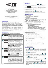
Connection Diagrams<br />
Connection Detail<br />
3 Ø 3 W Unbalanced load (2 element) 3 Ø 4W Unbalanced load (3 element)<br />
Wiring - Input connections are made directly to shrouded screw clamp terminal. Numbering is<br />
clearly marked on the plastic moulding. Choice of cable should meet local regulations. Terminals<br />
for both current and voltage inputs will accept up to 3mm 2 x 2 diameter cables.<br />
Auxiliary Supply - INTEGRA <strong>2000</strong> ideally should be powered by a dedicated supply, however it<br />
may be powered by the signal source, providing the source remains within ±10% of the chosen<br />
auxiliary voltage.<br />
Fusing - It is recommended that all voltage lines are fitted with 1 amp HRC fuses.<br />
Earth/Ground Connections - For safety reasons, CT secondary connections should be<br />
grounded according to local codes of practice.<br />
Import/Export Connections - The connections shown assume an import power configuration<br />
and therefore power factor is shown as import (IMP). Current will flow towards the load, if<br />
current flows away from the load, in an export power situation, then the power factor indication<br />
will change to export (EXP). This negates the need for separate export connections, because<br />
Integra serves the full four conditions of power factor.<br />
5
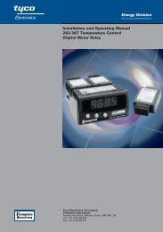
Operating Instructions<br />
Power measurement made easy with INTEGRA <strong>2000</strong><br />
On power up and in normal operation the INTEGRA <strong>2000</strong> displays the initial screen. This screen<br />
is factory set to display “Volts”, “Amps”, “Frequency” and “Watt”. It may be changed to display<br />
any four parameters. See the customisation section later in this guide.<br />
The INTEGRA <strong>2000</strong> screen<br />
The standard viewing screen has four active readings indicated.<br />
220.3V<br />
10.55A<br />
50.17Hz<br />
2.294kW<br />
220.3V avg<br />
10.55A sum<br />
50.17Hz sys<br />
2.294kW sum<br />
avg<br />
sum<br />
sys<br />
sum<br />
NEXT<br />
VOLTS<br />
AMPS<br />
Hz<br />
POWER<br />
CONFIG<br />
By character size and one key soft prompt.<br />
1st size Largest characters - the active readings. Four digits<br />
with dynamic scaling.<br />
2nd size The parameters for active readings with dynamic<br />
scaling to reflect Kilo, Mega etc.<br />
3rd size Indicate the relationship of the active reading to the<br />
measured system, e.g. L-L, sum etc.<br />
4th size Smallest characters - offers the key legends which<br />
guide the user through the menus of the instrument.<br />
“Next” is the only available key function on this screen.<br />
Press the “NEXT” key.<br />
The default screen now reduces in size to reveal the first level<br />
of key legends, all readings are still active.<br />
Each key now takes the user down to a new level of the menu<br />
structure.<br />
This can be demonstrated by pressing ”Power”<br />
Press “POWER”<br />
2.294kW sum<br />
371.5VArsum<br />
50.17kVAsum<br />
0.894PF<br />
imp<br />
WATT<br />
VAR<br />
VA<br />
PF PA<br />
EXIT<br />
The first level power screen by default shows active readings of<br />
W, VAr, VA and PF PA.<br />
(From this level down exiting all screens is easily done by a<br />
single keystroke “Exit”.)<br />
Next example press the “WATT” button.<br />
6
760.6W L1<br />
768.0W L2<br />
765.2W L3<br />
2.294kW sum<br />
MIN<br />
MAX<br />
HOURS<br />
HOLD<br />
This screen now displays active reading of Watt by Line<br />
and Sum<br />
The soft prompts keys now available are “MIN”, “MAX”,<br />
“HOURS” and “HOLD”.<br />
Press “HOURS”<br />
EXIT<br />
Press “ENERGY”<br />
ENERGY<br />
DEMANDS<br />
EXIT<br />
00000000 kWh Imp<br />
00000000 kWh Exp<br />
00000000 kVArh Imp<br />
00000000 kVArh Exp<br />
00000000 kVAh Sum<br />
00000000 kAh Sum<br />
EXIT<br />
This screen displays all Hour related functions, both import<br />
and export where appropriate.<br />
Press “EXIT” and this will revert to the previous screen.<br />
Press “DEMANDS”<br />
ENERGY<br />
DEMANDS<br />
EXIT<br />
7
00.00Wd IMP<br />
RESET<br />
Press “SETMAX” to return the maximum demand to the<br />
present demand value.<br />
Press “RESET” to begin or re-start the demand period<br />
00.00Wd MAX<br />
SETMAX<br />
Press “EXIT” twice<br />
00.00Wd EXP<br />
00.00Wd MAX<br />
INTERVALS IN PERIOD 00<br />
INTERVALS COMPLETED 00 EXIT<br />
Press “HOLD”<br />
760.6W L1<br />
768.0W L2<br />
765.2W L3<br />
2.294kW SUM<br />
MIN<br />
MAX<br />
HOURS<br />
HOLD<br />
EXIT<br />
760.6W<br />
768.0W<br />
765.2W<br />
2.294kW<br />
L1<br />
L2<br />
L3<br />
SUM<br />
This will expand the active screen to full size. This screen<br />
remains until deactivated by pressing “EXIT” where it<br />
will return to the reduced active screen.<br />
Press “EXIT”<br />
EXIT<br />
760.6W L1<br />
768.0W L2<br />
765.2W L3<br />
2.294kW SUM<br />
MIN<br />
MAX<br />
HOURS<br />
HOLD<br />
The minimum and maximum values are stored for each<br />
reading.<br />
The minimum and maximum values can be reset at the<br />
customisation screen.<br />
Press “MIN”<br />
EXIT<br />
8
760.6W<br />
768.0W<br />
765.2W<br />
2.294kW<br />
MINIMUM VALUES<br />
L1<br />
L2<br />
L3<br />
SUM<br />
EXIT<br />
The minimum values are shown.<br />
Press “EXIT”<br />
Press “MAX” shows the maximum values.<br />
Press “EXIT”<br />
Press “EXIT” again<br />
2.294kW<br />
sum<br />
WATT<br />
All the screen stages for “WATT” are repeated for “VAR”<br />
and “VA”.<br />
371.5VAr<br />
sum<br />
VAR<br />
Press “PF PA”<br />
40.17kVA<br />
sum<br />
VA<br />
0.894PF<br />
imp<br />
PF PA<br />
EXIT<br />
PF<br />
On pressing “PF PA” the display offers two choices for<br />
displaying the phase relationships: Power Factor (“PF”) and<br />
Phase Angle (“ANGLE”).<br />
ANGLE<br />
Either choice will give the same information, displayed in the<br />
chosen way.<br />
Press “PF”<br />
EXIT<br />
The power factor for each phase, and the sum, is displayed.<br />
Two pieces of information are shown to indicate the<br />
Quadrant in which the load is operating:<br />
1.000PF IMP L1<br />
1.000PF IMP L2<br />
1.000PF IMP L3<br />
1.000PF<br />
IMP SYS<br />
EXIT<br />
A symbol is used to indicate a Capacitive ( ) or Inductive<br />
( ) load. The direction is shown as “IMP” for Importing and<br />
“EXP” Exporting.<br />
The only soft prompt available is “EXIT” which will take you<br />
to the previous screen.<br />
The “EXIT” button is pressed as many times as necessary to<br />
return to the first menu screen. Note that if a key is not<br />
pressed for approximately one minute the display will<br />
automatically revert to the initial screen. This will not occur if<br />
a screen has been held by using the “HOLD” button.<br />
9
2.294kW avg<br />
10.55A sum<br />
50.17Hz<br />
sys<br />
2.294kW sum<br />
PASSCODE<br />
0000<br />
VOLTS<br />
AMPS<br />
Hz<br />
POWER<br />
CONFIG<br />
SYSTEM<br />
PASS<br />
CODE<br />
RESET<br />
SETUP<br />
EXIT<br />
SYSTEM<br />
PASS<br />
CODE<br />
RESET<br />
SETUP<br />
EXIT<br />
SYSTEM<br />
INC<br />
DEC<br />
OK<br />
EXIT<br />
Customisation<br />
Press “NEXT”<br />
Press “CONFIG”<br />
This enters into the customising area of the menu structure. All<br />
critical functions request confirmation. Pressing “EXIT” again<br />
allows easy escape without change.<br />
The unit will revert to the initial screen approximately one<br />
minute after the last keypress. This means it cannot be left in a<br />
configuration menu. Any partially completed changes will be<br />
discarded.<br />
There are four main options:<br />
“SYSTEM” Gives status information for field service personnel.<br />
“PASSCODE” Allows the user to change the protection passcode<br />
“RESET” Allows the user to clear the hours related counters, the<br />
Minimum and Maximum values and the Demand values.<br />
“SETUP” Allows the user to customise the Scaling, Demand<br />
period and Output options if fitted.<br />
Press “SYSTEM”<br />
The “SYSTEM” screen provides the following information:<br />
●<br />
Firmware version.<br />
● Communications speed, number of data bits, number of<br />
stop bits, parity and address.<br />
● Protocol installed<br />
● Electrical system configuration.<br />
Press “EXIT”<br />
Passcode<br />
Press “PASSCODE”<br />
All settings that alter the operation of the unit are passcode<br />
protected. The user must enter the correct code before access to<br />
the configuration menu is allowed.<br />
NOTE: The factory default setting is “0000”<br />
Once this passcode has been entered, it remains valid for all<br />
menus. If the keys are not pressed for a one minute period the<br />
unit exits the configuration menu and returns to the default<br />
screen. The passcode will have to be re-entered for any further<br />
configuration.<br />
The passcode is a number between 0000 and 9999. It can be<br />
changed by the user to any number. The factory default is 0000.<br />
Pressing “OK” with the factory default password will allow<br />
access to the customisation.<br />
NOTE: To secure system settings, countries and configuration a<br />
password should always be used.<br />
10
PASSCODE<br />
CORRECT<br />
SYSTEM<br />
INC<br />
DEC<br />
OK<br />
EXIT<br />
SYSTEM<br />
PASS<br />
CODE<br />
RESET<br />
SETUP<br />
EXIT<br />
To select the passcode, the “INC” and “DEC” keys are<br />
used to increment and decrement the displayed number.<br />
Pressing the “DEC” key with 0000 displayed will change<br />
the number to 9999.<br />
The number will automatically increment and decrement if<br />
the “INC” or “DEC” key is held depressed. The longer the<br />
key is held, the faster the numbers will change.<br />
Once the correct number is displayed, press the “OK”<br />
button.<br />
If the displayed passcode matches the correct value, the<br />
screen will show “PASSCODE CORRECT” and return to the<br />
previous screen.<br />
Changing the Passcode<br />
NOTE: If the current passcode has not been entered during<br />
this configuration session the user will be prompted to<br />
enter it at this stage.<br />
Press “EXIT”<br />
Press “PASSCODE”<br />
ENTER NEW<br />
PASS CODE<br />
0000<br />
SYSTEM<br />
INC<br />
DEC<br />
OK<br />
EXIT<br />
To select the new passcode, the “INC” and “DEC” keys are<br />
used to increment and decrement the displayed number.<br />
Pressing the “DEC” key with 0000 displayed will change<br />
the number to 9999.<br />
The number will automatically increment and decrement if<br />
the “INC” or “DEC” key is held depressed. The longer the<br />
key is held, the faster the numbers will change.<br />
Once the desired number is displayed, press the “OK”<br />
button.<br />
SYSTEM<br />
PASS<br />
CODE<br />
RESET<br />
SETUP<br />
EXIT<br />
The screen will return to the previous menu<br />
NOTE : If the password is changed and subsequently<br />
forgotten, please contact your nearest sales and service<br />
centre for assistance. A list of telephone numbers and<br />
addresses is printed on the rear cover of this manual.<br />
Press “RESET”<br />
11
HOURS<br />
MIN<br />
MAX<br />
DEMAND<br />
Resetting Stored Values<br />
This menu allows the user to reset any of the stored<br />
values. These include all the hours related parameters<br />
( W.h, VAr.h, VA.h, A.h), the Minimum values, the<br />
Maximum values and the Demand values.<br />
Press “HOURS”<br />
EXIT<br />
WATT<br />
VAR<br />
VA<br />
Press “WATT” to zero accumulated W.h. “RESET” will<br />
appear to the left indicating this choice has been made.<br />
A similar function is performed by the “VAR”, “VA” and<br />
“A” keys.<br />
Press “EXIT”<br />
A<br />
EXIT<br />
ACCEPT<br />
CHANGES<br />
TO SYSTEM<br />
COUNTERS<br />
YES<br />
The screen now asks the operator to confirm changes.<br />
“YES” will implement the changes and take the user back<br />
to the reset screen.<br />
“NO” will not implement the changes, but will also take<br />
the user back to the reset screen.<br />
NO<br />
HOURS<br />
MIN<br />
MAX<br />
The “MIN”, “MAX” and “DEMAND” keys perform a similar<br />
function to the stored minimum, maximum and demand<br />
values.<br />
Press “EXIT”<br />
DEMAND<br />
EXIT<br />
12
Setting up the INTEGRA <strong>2000</strong> display<br />
SYSTEM<br />
PASS<br />
CODE<br />
Press “SETUP”<br />
RESET<br />
SETUP<br />
EXIT<br />
This screen offers four options:<br />
“DISPLAY” allows the user to adjust the display update time.<br />
DISPLAY<br />
SYSTEM SETTINGS<br />
DEMAND PERIOD<br />
OUTPUTS<br />
EXIT<br />
“SYSTEM SETTINGS” allows the user to enter CT and VT<br />
ratios. The unit will then display all parameters scaled to the<br />
primary values.<br />
“DEMAND PERIOD” allows the user to change the<br />
<strong>integra</strong>tion period of the Maximum Demand functions. The<br />
same interval is used for all parameters.<br />
“OUTPUTS” allows the configuration of the optional output<br />
modules.<br />
Press “DISPLAY”<br />
UPDATE RATE<br />
Press “UPDATE RATE”. This screen allows the screen update<br />
time to be modified. The standard update time is<br />
approximately 100ms but users can progamme the Integra<br />
<strong>2000</strong> to override up to 20 updates thereby avoiding digit roll.<br />
Analogue and digital outputs are not affected by this feature.<br />
The bar flashes at the selected rate to assist selection.<br />
EXIT<br />
20 MORE<br />
LESS<br />
EXIT<br />
Press and hold the “MORE” or “LESS” buttons, this will<br />
increment the number on the far left or the screen.<br />
The higher the number, (“MORE”) the higher the number of<br />
updates missed.<br />
The lower the number, (“LESS”) the lower the number of<br />
updates missed.<br />
Press “EXIT” twice to return to the set-up screen.<br />
13
System Settings<br />
DISPLAY<br />
Press “SYSTEM SETTINGS”<br />
SYSTEM SETTINGS<br />
DEMAND PERIOD<br />
OUTPUTS<br />
EXIT<br />
By pressing “SET AMPS TO SUM” you answer a question.<br />
SET AMPS TO SUM<br />
SYSTEM VALUE<br />
EXIT<br />
230.0V<br />
INC<br />
5.000A<br />
COL<br />
ROW<br />
3.450kW<br />
DP<br />
SETUP SYSTEM VOLTAGE<br />
EXIT<br />
230.0V<br />
INC<br />
5.000A<br />
COL<br />
ROW<br />
3.450kW<br />
DP<br />
SETUP SYSTEM VOLTAGE<br />
EXIT<br />
“SET AMPS TO SUM” or “SET AMPS TO AVERAGE”<br />
This screen if the sum on the average of the three phases<br />
of current are displayed on the default screen.<br />
Press “SYSTEM VALUES”<br />
This screen is used to set up the primary system voltage<br />
and current values. The values entered here should be the<br />
primary values of the system CT’s and VT’s.<br />
e.g. if a 40/5 CT is used, the current setting should read 40.<br />
For a 4 wire system, the voltage value is the Line to<br />
Neutral (L-N) voltage.<br />
For a 3 wire system, the voltage value is the Line to Line<br />
(L-L) voltage.<br />
“INC” increments the selected character over its available<br />
range<br />
e.g. numbers = 0 to 9<br />
parameters = V, kV, etc.<br />
●<br />
If 6.8kV/110V VT is used, the voltage setting should<br />
read 6.800kV. The VT secondary voltage must be the<br />
same as the product voltage given on the label.<br />
● If no VT is used, the voltage setting must be the same<br />
as the product voltage given on the label.<br />
“COL” selects the column to be chaned by the “INC”<br />
button. The digit to be changed goes in to inverse mode.<br />
“DP” (Decimal Point) Selects the correct decimal point<br />
position.<br />
Change the voltage value to match the system primary<br />
value. When this has been done, press the “ROW” button.<br />
14
230.0V<br />
5.000A<br />
3.450kW<br />
SETUP SYSTEM VOLTAGE<br />
INC<br />
COL<br />
ROW<br />
DP<br />
EXIT<br />
Change the current value to match the system primary<br />
value.<br />
Note: The watt reading will update automatically.<br />
Press “EXIT”<br />
230.0V<br />
5.000A<br />
3.450kW<br />
SETUP SYSTEM VOLTAGE<br />
INC<br />
COL<br />
ROW<br />
DP<br />
EXIT<br />
ACCEPT<br />
CHANGES<br />
TO SYSTEM<br />
V AND I<br />
YES<br />
NO<br />
This screen now asks the operator to confirm changes.<br />
“YES” will implement the changes and take the user back<br />
to the “SETUP” screen.<br />
“NO” will not implement the changes but will also take the<br />
user back to the “SETUP” screen<br />
Press “EXIT”<br />
15
Demand Period<br />
DISPLAY<br />
SYSTEM SETTING<br />
DEMAND PERIOD<br />
OUTPUTS<br />
ACCEPT<br />
CHANGES<br />
TO DEMAND<br />
PERIOD<br />
EXIT<br />
YES<br />
Press “DEMAND PERIOD”<br />
This screen sets up the two parameters that define the<br />
averaging response. Refer to Appendix A for further<br />
information. This uses the same procedure as the previous<br />
set up screen.<br />
The SUB INTERVAL LENGTH can be any value between 1<br />
and 30 minutes. The NUMBER OF SUB INTERVALS can be<br />
any value between 1 and 30.<br />
On completion, press “EXIT”<br />
Accept or ignore changes here.<br />
NO<br />
16
Outputs<br />
DISPLAY<br />
SYSTEM SETTING<br />
DEMAND PERIOD<br />
OUTPUTS<br />
EXIT<br />
Press “OUTPUTS”<br />
This screen lists the available output options supported by<br />
the unit. Note that although the software can be<br />
configured, additional hardware output modules may be<br />
required. Contact your local sales and service centre for<br />
assistance.<br />
Setting up the INTEGRA <strong>2000</strong> RS485 output<br />
RS485<br />
Press “RS485”<br />
ANALOGUE<br />
OUTPUTS<br />
PULSED<br />
OUTPUTS<br />
USER SCREEN<br />
EXIT<br />
BAUD 9600<br />
PARITY NONE<br />
STOP BITS 2<br />
ADDRESS 001<br />
ACCEPT<br />
CHANGES<br />
INC<br />
DEC<br />
ROW<br />
EXIT<br />
YES<br />
NO<br />
This screen allows the user to configure the parameters for<br />
the RS485 port. NOTE: Communicatios settings for<br />
Johnsons Controls are fixed and pre set. A pointer is<br />
shown next to the value being changed. The “INC” and<br />
“DEC” keys are used to increment and decrement the<br />
displayed value. The “ROW” key is user to move the<br />
pointer to the next parameter.<br />
The Baud rate is selectable to 2400, 4800, 9600 and 19,200.<br />
The Parity can be set to EVEN, ODD or NONE.<br />
The Stop Bits are adjusted automatically, depending on the<br />
Parity setting.<br />
The address can be set to any value between 001 and 247.<br />
Address 0 (Broadcast mode) is not supported.<br />
Press “EXIT” when the values have been amended<br />
correctly<br />
The screen now asks the operator to confirm changes.<br />
“YES” will implement the changes<br />
“NO” will discard the changes.<br />
Pressing either key will take the user back to the output<br />
screen.<br />
17
Analogue Outputs<br />
RS485<br />
ANALOGUE<br />
OUTPUTS<br />
PULSED<br />
OUTPUTS<br />
USER SCREEN<br />
EXIT<br />
Press “ANALOGUE OUTPUTS”<br />
This screen assigns a parameter to each of the four analogue<br />
outputs.<br />
“INC” cycles the selected parameter forward through the list.<br />
“DEC” cycles the selected parameter backwards through<br />
the list.<br />
“ROW” moves the pointer to the next output channel.<br />
All of the keys will auto-repeat if held down.<br />
NONE<br />
NONE<br />
NONE<br />
NONE<br />
INC<br />
DEC<br />
ROW<br />
SETUP ANALOGUE OUTPUT 1<br />
EXIT<br />
* = For Watts and Vars, the<br />
output is positive for both<br />
Import and Export<br />
directions.<br />
** = 3 phase 4 wire mode only.<br />
Parameter Description Scaling<br />
NONE No assigned value Zero<br />
V 1 Volts 1 0-100%<br />
V 2 Volts 2 0-100%<br />
V 3 Volts 3 0-100%<br />
V AVG Volts Average 0-100%<br />
V L1/L2 Volts L1-L2 0-100%**<br />
V L2/L3 Volts L2-L3 0-100%**<br />
V L3/L1 Volts L3-L1 0-100%**<br />
V L/L AVG Volts L-L Average 0-100%**<br />
I 1 Current 1 0-100%<br />
I 2 Current 2 0-100%<br />
I 3 Current 3 0-100%<br />
I SUM Current Sum 0-100%<br />
I AVG Current Average 0-100% *<br />
I NEUTRAL Neutral Current 0-100% *<br />
W 1 IMP Watts 1 Import 0-100% *<br />
W 2 IMP Watts 2 Import 0-100% *<br />
W 3 IMP Watts 3 Import 0-100% *<br />
W SUM IMP Watts Sum Import 0-100% *<br />
W 1 EXP Watts 1 Export 0-100% *<br />
W 2 EXP Watts 2 Export 0-100% *<br />
W 3 EXP Watts 3 Export 0-100% *<br />
W SUM EXP Watts Sum Export 0-100% *<br />
VAR 1 IMP VAr 1 Import 0-100% *<br />
VAR 2 IMP VAr 2 Import 0-100% *<br />
VAR 3 IMP VAr 3 Import 0-100% *<br />
VAR SUM IMP VAr Sum Import 0-100% *<br />
VAR 1 EXP VAr 1 Export 0-100% *<br />
VAR 2 EXP VAr 2 Export 0-100% *<br />
VAR 3 EXP VAr 3 Export 0-100% *<br />
VAR SUM EXP VAr Sum Export 0-100% *<br />
VA 1 VA 1 0-100%<br />
VA 2 VA 2 0-100%<br />
VA 3 VA 3 0-100%<br />
VA SUM VA Sum 0-100%<br />
HZ Frequency 45-65 Hz<br />
PHANGLE 1 Phase Angle 1 +180° / 0 / -180°<br />
PHANGLE 2 Phase Angle 2 +180° / 0 / -180°<br />
PHANGLE 3 Phase Angle 3 +180° / 0 / -180°<br />
ANGLE AVG Phase Angle Average +180° / 0 / -180°<br />
PF 1 Power Factor 1 +180° / 0 / -180°<br />
PF 2 Power Factor 2 +180° / 0 / -180°<br />
PF 3 Power Factor 3 +180° / 0 / -180°<br />
PF AVG Power Factor AVG +180° / 0 / -180°<br />
18
V AVG<br />
W SUM<br />
PF AVG<br />
NONE<br />
INC<br />
DEC<br />
ROW<br />
If any output is assigned to be “NONE”, a zero value will<br />
be transmitted.<br />
The same value may be assigned to more than one output<br />
if necessary.<br />
Once all four outputs have been assigned, press “EXIT”<br />
SETUP ANALOGUE OUTPUT 4<br />
EXIT<br />
ACCEPT<br />
CHANGES<br />
YES<br />
The screen now asks the operator to confirm changes.<br />
“YES” will implement the changes<br />
“NO” will discard the changes<br />
Pressing either key will take the user back to the output<br />
screen.<br />
NO<br />
19
Pulsed Outputs<br />
RS485<br />
ANALOGUE<br />
OUTPUTS<br />
PULSED<br />
OUTPUTS<br />
Press “PULSED OUTPUTS”<br />
USER SCREEN<br />
EXIT<br />
This menu has three options:<br />
ASSIGN<br />
DIVISOR<br />
PULSE LENGTH<br />
EXIT<br />
“ASSIGN” assigns a parameter to each output<br />
“DIVISOR” enables a divide ratio of 10, 100 or 1000<br />
“PULSE LENGTH” sets the duration of the pulse length from<br />
20mS to 200mS<br />
Press “ASSIGN”<br />
This screen assigns a parameter to each of the pulsed outputs.<br />
NONE<br />
0000 PPH<br />
NONE<br />
0000 PPH<br />
INC<br />
DEC<br />
ROW<br />
SETUP PULSED OUTPUT 1<br />
EXIT<br />
“INC” cycles the selected parameter forward through the list.<br />
“DEC” cycles the selected parameter backwards through the<br />
list.<br />
“ROW” moves the pointer to the other output channel.<br />
All of the keys will autorepeat if held down.<br />
The line reading “0000 PPH” indicates how many pulses per<br />
hour will be output for that parameter at full scale power.<br />
This number is automatically determined by the unit from<br />
the VT and CT ratio settings made in the main setup menu.<br />
The number of pulses may be divided down using the<br />
“DIVISOR” option, described later.<br />
NOTE: The maximum pulse rate is 3600 pulses per hour.<br />
Suitable for systems up to 3.6 MW (3,600 kW). If greater than<br />
3.6 MW pulses autorange to 1 pulse per MW.h.<br />
The list of parameters is as follows:<br />
Parameter<br />
NONE<br />
IMP WATT HR<br />
EXP WATT HR<br />
IMP VAR HR<br />
EXP VAR HR<br />
VA HOUR<br />
AMP HOUR<br />
Description<br />
No assigned value<br />
Import Watt Hours<br />
Export Watt Hours<br />
Import VAr Hours<br />
Export VAr Hours<br />
VA Hours<br />
Amp Hours<br />
20
VA HOUR<br />
3450 PPH<br />
NONE<br />
0000 PPH<br />
INC<br />
DEC<br />
ROW<br />
If any output is assigned to be “NONE”, no pulses will be<br />
transmitted.<br />
The same value may be assigned to more than one output<br />
if necessary.<br />
Once both outputs have been assigned, press “EXIT”<br />
SETUP PULSED OUTPUT 2<br />
EXIT<br />
ACCEPT<br />
CHANGES<br />
YES<br />
The screen now asks the operator to confirm changes.<br />
“YES” will implement the changes<br />
“NO” will discard the changes<br />
Pressing either key will take the user back to the pulsed<br />
output screen.<br />
NO<br />
ASSIGN<br />
DIVISOR<br />
PULSE LENGTH<br />
The “DIVISOR” screen enables a divide ratio of 10, 100 or<br />
1000. This allows the user to program the unit to output a<br />
lower number of pulses according to the system<br />
requirements. For example, setting the divisor to 1000 will<br />
output kilowatt hour pulses, and setting the divisor to 1<br />
will output Watt hour pulses.<br />
Press “DIVISOR”<br />
1<br />
3450 PPH<br />
1000<br />
3.450 PPH<br />
EXIT<br />
INC<br />
DEC<br />
ROW<br />
SETUP PULSED DIVISOR 2<br />
EXIT<br />
This screen assigns a divisor value to each of the pulsed<br />
outputs.<br />
“INC” cycles the value between 1, 10, 100 and 1000.<br />
“DEC” cycles the value backwards through the list.<br />
“ROW”moves the pointer to the other output channel.<br />
All of the keys will autorepeat if held down.<br />
Note that the Pulses per hour (PPH) figure is automatically<br />
calculated to show the number of pulses that will be<br />
transmitted at full-scale power.<br />
NOTE: If the system power is scaled in kW then the default<br />
pulse rate is 1 pulser perkWh (up to 3,600 kW system).<br />
If the system power (see system settings) is over 3.6 MW<br />
then the pulse rates adjust accordingly to 1 pulse<br />
per MWh.<br />
21
ACCEPT<br />
CHANGES<br />
YES<br />
The screen now asks the operator to confirm changes.<br />
“YES” will implement the changes<br />
“NO” will discard the changes<br />
Pressing either key will take the user back to the pulsed<br />
output screen.<br />
NO<br />
ASSIGN<br />
DIVISOR<br />
PULSE LENGTH<br />
The “PULSE LENGTH” screen enables the width of each<br />
output pulse to be adjusted in 20mS increments between<br />
20 and 200mS.<br />
Press “PULSE LENGTH”<br />
EXIT<br />
20<br />
MILLISECONDS<br />
200<br />
MILLISECONDS<br />
SETUP PULSED LENGTH<br />
INC<br />
DEC<br />
ROW<br />
EXIT<br />
“INC” increases the value in 20mS increments up to a<br />
maximum of 200mS<br />
“DEC” decreases the value in 20mS increments down to a<br />
minimum of 20mS<br />
“ROW”moves the pointer to the other output channel.<br />
All of the keys will autorepeat if held down.<br />
ACCEPT<br />
CHANGES<br />
YES<br />
NO<br />
The screen now asks the operator to confirm changes.<br />
“YES” will implement the changes<br />
“NO” will discard the changes<br />
Pressing either key will take the user back to the pulsed<br />
output screen.<br />
Press “EXIT” again to return to the output screen<br />
22
Setting up the INTEGRA <strong>2000</strong> user screen<br />
RS485<br />
ANALOGUE<br />
OUTPUTS<br />
PULSED<br />
OUTPUTS<br />
USER SCREEN<br />
EXIT<br />
The unit defaults to an initial screen after a period of one<br />
minute from the last button press. This initial screen may<br />
be changed to display particular parameters of interest.<br />
The factory default setting of Vavg, Asum, Hz and Wsum is<br />
shown if a user screen is not programmed, or if all choices<br />
are set to NONE.<br />
Press “USER SCREEN”<br />
NONE<br />
NONE<br />
NONE<br />
NONE<br />
INC<br />
DEC<br />
ROW<br />
SETUP USER SCREEN LINE 1<br />
EXIT<br />
This screen assigns a parameter to each of the four screen<br />
lines.<br />
“INC” cycles the selected parameter forward through the<br />
list.<br />
“DEC” cycles the selected parameter backwards through<br />
the list.<br />
“ROW”moves the pointer to the next zone.<br />
All of the keys will autorepeat if held down.<br />
The list of parameters is as follows:<br />
Parameter Description<br />
NONE No assigned value<br />
V 1 Volts 1<br />
V 2 Volts 2<br />
V 3 Volts 3<br />
V AVG Volts Average<br />
V L1/L2 Volts L1-L2*<br />
V L2/L3 Volts L2-L3*<br />
V L3/L1 Volts L3-L1*<br />
V L/L AVG Volts L-L Average*<br />
I 1 Current 1<br />
I 2 Current 2<br />
I 3 Current 3<br />
I SUM Current Sum<br />
I AVG Current Average<br />
I NEUTRAL Neutral Current<br />
W 1 Watts 1<br />
W 2 Watts 2<br />
W 3 Watts 3<br />
W SUM Watts Sum<br />
VAR 1 VAr 1<br />
VAR 2 VAr 2<br />
VAR 3 VAr 3<br />
VAR SUM VAr Sum<br />
Parameter Description<br />
VA 1 VA 1<br />
VA 2 VA 2<br />
VA 3 VA 3<br />
VA SUM VA Sum<br />
HZ<br />
Frequency<br />
PHANGLE 1 Phase Angle 1<br />
PHANGLE 2 Phase Angle 2<br />
PHANGLE 3 Phase Angle 3<br />
ANGLE AVG Phase Angle Average<br />
PF1 Power Factor 1<br />
PF2 Power Factor 2<br />
PF3 Power Factor 3<br />
PF AVG Power Factor Average<br />
IMP WATT HR Import Watt Hours<br />
EXP WATT HR Export Watt Hours<br />
IMP VAR HR Import Var Hours<br />
EXP VAR HR Export Var Hours<br />
VA HOUR VA Hours<br />
AMP HOUR Amp Hours<br />
* = 3 phase 4 wire mode only<br />
23
V AVG<br />
W SUM<br />
PF AVG<br />
NONE<br />
INC<br />
DEC<br />
ROW<br />
If any line is assigned to be “NONE”, a blank space will be<br />
shown. If all four lines are assigned “NONE” the factory<br />
default screen of Vavg, Asum, Hz and Wsum is shown.<br />
Once all four lines have been assigned, press “EXIT”<br />
SETUP USER SCREEN LINE 4<br />
EXIT<br />
ACCEPT<br />
CHANGES<br />
YES<br />
The screen now asks the operator to confirm changes.<br />
“YES” will implement the changes<br />
“NO” will discard the changes<br />
Pressing either key will take the user back to the output<br />
screen.<br />
NO<br />
Press “EXIT” once again to return to the setup screen.<br />
DISPLAY<br />
SYSTEM SETTINGS<br />
Press “EXIT” to return to the configuration screen.<br />
Press “EXIT” to return to the measurement screen.<br />
DEMAND PERIOD<br />
OUTPUTS<br />
EXIT<br />
2.294kW avg<br />
10.55A sum<br />
50.17Hz<br />
sys<br />
2.294kW sum<br />
VOLTS<br />
AMPS<br />
Hz<br />
POWER<br />
CONFIG<br />
The user is returned to the first menu screen.<br />
If no user screen has been defined the soft prompts will<br />
disappear after a short time and will return to the large<br />
character active reading screen.<br />
If a user screen has been defined this will be shown<br />
immediately.<br />
Normally the characters will retain their usual size, i.e.<br />
voltage being the largest size and energy the second size.<br />
However, if one of the lines selected is normally the<br />
second size then all lines will also be the second size.<br />
24
µp<br />
1010<br />
RS485 Cable<br />
Option 1 - RS485 Digital Outputs<br />
MODBUS® Implementation<br />
INTEGRA <strong>2000</strong> offers the option of a RS485 communication module for direct connection to<br />
SCADA systems using the MODBUS® RTU protocol.<br />
The MODBUS‚ protocol establishes the format for the master's query by placing into it the<br />
device address, a function code defining the requested action, any data to be sent, and an error<br />
checking field. The slave's response message is also constructed using Modbus protocol. It<br />
contains fields confirming the action taken, any data to be returned, and an error checking field.<br />
If an error occurred in receipt of the message, or if the slave is unable to perform the requested<br />
action, the slave will construct an error message and send it as its response.<br />
The electrical interface is 2-wire RS485 (half duplex), via a 3 way 2 part connector. Connection<br />
should be made using twisted pair screened cable (Typically 22 gauge Belden 8761 or<br />
equivalent). All "A" and "B" connections are daisy chained together. The screens should also be<br />
connected to the “Gnd” terminal. To avoid the possibility of loop currents, an Earth connection<br />
should be made at one point on the network. See the connection diagram for details.<br />
A total maximum length of 1200M is allowed for the RS485 network. A maximum of 32 electrical<br />
nodes can be connected, including the controller. The cable should be terminated with a resistor<br />
at each end.<br />
The address of each Integra <strong>2000</strong> can be set to any value between 1 and 247. Broadcast mode<br />
(address 0) is not supported.<br />
The maximum latency time of an Integra <strong>2000</strong> is 200mS (Average 50mS) i.e. this is the amount<br />
of time that can pass before the first response character is output. The supervisory programme<br />
must allow this period of time to elapse before assuming that the INTEGRA <strong>2000</strong> is not going to<br />
respond.<br />
25
The format for each byte in RTU mode is:<br />
Coding System: 8-bit binary, hexadecimal 0-9, A-F<br />
Two hexadecimal characters contained in each 8-bit field of the message.<br />
Data Format: 4 bytes (32 bits) per parameter.<br />
Floating point format ( to IEEE 754)<br />
Most significant byte first.<br />
Reversed format available upon request.<br />
Bits per Byte: 1 start bit<br />
8 data bits, least significant bit sent first<br />
1 bit for even/odd parity; no bit for no parity<br />
1 stop bit if parity is used; 2 bits if no parity<br />
Error Check Field: Cyclical Redundancy Check (CRC)<br />
Data Transmission speed is selectable between 2400, 4800, 9600, 19200bps<br />
All settings are user configurable via the setup screens.<br />
The <strong>Crompton</strong> <strong>Instruments</strong> “Guide to RS485 communications” and “The Modbus® protocol - a<br />
detailed guide” can be viewed from the CD catalogue or website.<br />
See the customisation section for details.<br />
Register Addresses<br />
Each parameter is held in a consecutive word address as defined in the Modbus Protocol. The<br />
following table details these addresses. A tick (√) in the column indicates that the parameter is<br />
valid for that wiring system. Any parameter with a cross (X) will return the value Zero (0h).<br />
Each parameter is held in the 3X registers. Modbus Code 04 is used to access all parameters.<br />
e.g. to request: Volts 1 Start address = 00<br />
N° of words = 02<br />
Volts 2 Start address = 02<br />
N° of words = 02<br />
Each request for data must be restricted to 20<br />
parameters or less. Violating this requirement will<br />
impact the performance of the instrument.<br />
Address Parameter Wire<br />
4 3 2<br />
1 Demand Time √ √ √<br />
2 Number of Sub-Intervals √ √ √<br />
3 Sub-Interval Length √ √ √<br />
The DEMAND parameters may be viewed or<br />
changed using the MODBUS protocol. Each<br />
parameter is held in the 4X registers. Modbus Code 03 is used to read these parameters and<br />
code 16 to write to them.<br />
The Demand Time (Address 1) is used to reset the demand period. A value of zero (0) must be<br />
written to this register to accomplish this. Writing any other value will cause an error to be<br />
returned.<br />
The value written in to addresses 2 and 3 must be in the range 1 to 30, otherwise an error will<br />
be returned.<br />
See Appendix A for further information on the Demand Parameters.<br />
28
Modbus® Register Addresses<br />
Parameter<br />
No<br />
Modbus Start<br />
Address<br />
High<br />
Byte<br />
Parameter Integra <strong>2000</strong><br />
Configuration<br />
Low<br />
(No of Wires)<br />
Byte 4 3 2<br />
1 00 00 Volts 1 ✓ ✓ ✓<br />
2 00 02 Volts 2 ✓ ✓ X<br />
3 00 04 Volts 3 ✓ ✓ X<br />
4 00 06 Current 1 ✓ ✓ ✓<br />
5 00 08 Current 2 ✓ ✓ X<br />
6 00 0A Current 3 ✓ ✓ X<br />
7 00 0C Watts 1 ✓ X ✓<br />
8 00 0E Watts 2 ✓ X X<br />
9 00 10 Watts 3 ✓ X X<br />
10 00 12 VA 1 ✓ X ✓<br />
11 00 14 VA 2 ✓ X X<br />
12 00 16 VA 3 ✓ X X<br />
13 00 18 VAr 1 ✓ X ✓<br />
14 00 1A VAr 2 ✓ X X<br />
15 00 1C VAr 3 ✓ X X<br />
16 00 1E Power Factor 1 ✓ X ✓<br />
17 00 20 Power Factor 2 ✓ X X<br />
18 00 22 Power Factor 3 ✓ X X<br />
19 00 24 Phase Angle 1 ✓ X ✓<br />
20 00 26 Phase Angle 2 ✓ X X<br />
21 00 28 Phase Angle 3 ✓ X X<br />
22 00 2A Volts Ave ✓ ✓ ✓<br />
23 00 2C Reserved<br />
24 00 2E Current Ave ✓ ✓ ✓<br />
25 00 30 Current Sum ✓ ✓ ✓<br />
26 00 32 Reserved<br />
27 00 34 Watts Sum ✓ ✓ ✓<br />
28 00 36 Reserved<br />
29 00 38 VA Sum ✓ ✓ ✓<br />
30 00 3A Reserved<br />
31 00 3C VAr Sum ✓ ✓ ✓<br />
32 00 3E Power Factor Ave ✓ ✓ ✓<br />
33 00 40 Reserved<br />
34 00 42 Phase Angle Ave ✓ ✓ ✓<br />
35 00 44 Reserved<br />
36 00 46 Frequency ✓ ✓ ✓<br />
37 00 48 W.hr Import ✓ ✓ ✓<br />
38 00 4A W.hr Export ✓ ✓ ✓<br />
39 00 4C VAr.h Import ✓ ✓ ✓<br />
40 00 4E VAr.h Export ✓ ✓ ✓<br />
41 00 50 VA.h ✓ ✓ ✓<br />
42 00 52 A.h ✓ ✓ ✓<br />
43 00 54 W Demand Import ✓ ✓ ✓<br />
44 00 56 W Max. Demand ✓ ✓ ✓<br />
Import<br />
45 00 58 W Demand Export ✓ ✓ ✓<br />
46 00 5A W Max. Demand ✓ ✓ ✓<br />
Export<br />
47 00 5C VAr Demand Import ✓ ✓ ✓<br />
48 00 5E VAr Max Demand ✓ ✓ ✓<br />
Import<br />
49 00 60 VAr Demand Export ✓ ✓ ✓<br />
50 00 62 VAr Demand Export ✓ ✓ ✓<br />
51 00 64 VA Demand ✓ ✓ ✓<br />
52 00 66 VA Max. Demand ✓ ✓ ✓<br />
53 00 68 A Demand ✓ ✓ ✓<br />
54 00 6A A Max. Demand ✓ ✓ ✓<br />
55 00 6C Volts 1 Max. ✓ ✓ ✓<br />
Parameter<br />
No<br />
Modbus Start<br />
Address<br />
High<br />
Byte<br />
Parameter Integra <strong>2000</strong><br />
Configuration<br />
Low<br />
(No of Wires)<br />
Byte 4 3 2<br />
56 00 6E Volts 1 Min. ✓ ✓ ✓<br />
57 00 70 Volts 2 Max. ✓ ✓ X<br />
58 00 72 Volts 2 Min. ✓ ✓ X<br />
59 00 74 Volts 3 Max. ✓ ✓ X<br />
60 00 76 Volts 3 Min. ✓ ✓ X<br />
61 00 78 Current 1 Max. ✓ ✓ ✓<br />
62 00 7A Current 1 Min. ✓ ✓ ✓<br />
63 00 7C Current 2 Max. ✓ ✓ X<br />
64 00 7E Current 2 Min. ✓ ✓ X<br />
65 00 80 Current 3 Max. ✓ ✓ X<br />
66 00 82 Current 3 Min. ✓ ✓ X<br />
67 00 84 Volts Average Max. ✓ ✓ ✓<br />
68 00 86 Volts Average Min. ✓ ✓ ✓<br />
69 00 88 Reserved<br />
70 00 8A Volts Sum Min. X X X<br />
71 00 8C Reserved<br />
72 00 8E Reserved<br />
73 00 90 Current Sum Max. ✓ ✓ ✓<br />
74 00 92 Current Sum Min. ✓ ✓ ✓<br />
75 00 94 Watt 1 Max. ✓ X ✓<br />
76 00 96 Watt 1 Min. ✓ X ✓<br />
77 00 98 Watt 2 Max. ✓ X X<br />
78 00 9A Watt 2 Min. ✓ X X<br />
79 00 9C Watt 3 Max. ✓ X X<br />
80 00 9E Watt 3 Min. ✓ X X<br />
81 00 A0 Watt Sum Max. ✓ ✓ ✓<br />
82 00 A2 Watt Sum Min. ✓ ✓ ✓<br />
83 00 A4 VAr 1 Max. ✓ X ✓<br />
84 00 A6 VAr 1 Min. ✓ X ✓<br />
85 00 A8 VAr 2 Max. ✓ X X<br />
86 00 AA VAr 2 Min. ✓ X X<br />
87 00 AC VAr 3 Max. ✓ X X<br />
88 00 AE VAr 3 Min. ✓ X X<br />
89 00 B0 VAr Sum Max. ✓ ✓ ✓<br />
90 00 B2 VAr Sum Min. ✓ ✓ ✓<br />
91 00 B4 VA1 Max. ✓ X ✓<br />
92 00 B6 VA 1 Min. ✓ X ✓<br />
93 00 B8 VA 2 Max. ✓ X X<br />
94 00 BA VA 2 Min. ✓ X X<br />
95 00 BC VA3 Max. ✓ X X<br />
96 00 BE VA3 Min. ✓ X X<br />
97 00 C0 VA Sum Max. ✓ ✓ ✓<br />
98 00 C2 VA Sum Min. ✓ ✓ ✓<br />
99 00 C4 Frequency Max. ✓ ✓ ✓<br />
100 00 C6 Frequency Min. ✓ ✓ ✓<br />
101 00 C8 V L1-L2 ✓ X X<br />
102 00 CA V L2-L3 ✓ X X<br />
103 00 CC V L3-L1 ✓ X X<br />
104 00 CE V L-L Ave ✓ X X<br />
105 00 D0 V L1-L2 Max ✓ X X<br />
106 00 D2 V L1-L2 Min ✓ X X<br />
107 00 D4 V L2-L3 Max ✓ X X<br />
108 00 D6 V L2-L3 Min ✓ X X<br />
109 00 D8 V L3-L1 Max ✓ X X<br />
110 00 DA V L3-L1Min ✓ X X<br />
111 00 DC V L-L Ave Max ✓ X X<br />
112 00 DE V L-L Ave Min ✓ X X<br />
113 00 E0 I Neutral ✓ X X<br />
27
Appendix B: Instrument Holding Registers<br />
In the table the “System Configuration” is defined by the number of wires, 4 represents a 3<br />
phase 4 wire system, 3 represents a 3 phase 3 wire system and 2 represents a single phase<br />
system.<br />
Parameter<br />
No<br />
Modbus Start Address<br />
Parameter<br />
High Byte<br />
Low Byte<br />
1 00 00 Demand Time<br />
2 00 02 Demand Period<br />
3 00 04 Demand Interval<br />
4 00 06 System Volts<br />
5 00 08 System Current<br />
6 00 0A System Type<br />
7 00 0C Relay Pulse Width<br />
8 00 0E Energy Reset<br />
12 00 16 Pulse Width Divisor<br />
Important Note: Energy counters<br />
The front panel display has an 8-digit capability for 'kilowatt-hour' and 'kVAr-hour' values, and<br />
this count will automatically roll-over to zero once the 8-digit value exceeds 99,999,999. The<br />
associated Modbus registers are scaled in 'Watt-hour' and 'VAr-hour' and will automatically rollover<br />
to zero once a numerical value of 4,294,967,296 has been accumulated. The Modbus and<br />
display values are in-step until the energy count exceeds 4,294,967 kwh, after which the Modbus<br />
count starts again from zero, but the display count continues to increment. The display and<br />
Modbus counters can be re-synchronised by resetting the energy counters to zero, easily done<br />
through the Integra front panel or via Modbus by writing to a holding register.<br />
28
Output Connection Diagram<br />
Notes<br />
Line Topology<br />
Each end of the cable should be terminated with a resistor. A typical value is 600Ω. Consult the<br />
cable manufacturers data or the system interogator for the exact value. Depending on the cable<br />
used and the length of the cable run may not require any termination loading. The impedance of<br />
the termination load should match the impedance of the cable being used and should be at both<br />
ends of the line. The load should be made up of a resistor and a capacitor in series across the<br />
‘A’ and ‘B’ terminals.<br />
Loop Line Topology<br />
A loop ring topology may be used if preferred. In this case no termination resistors are required.<br />
Full Duplex/Half Duplex<br />
Integra is half duplex (2 wire) i.e. transmits and receives on the same pair of wires. If the master<br />
has 4 connections (2 receive and 2 transmit i.e. full duplex) then common +(A)’s together and<br />
also common both -(B)’s. However make sure PLC is RS485 (4 wire) and not RS422. Also check<br />
data synchronisation i.e. half or full duplex. The PLC must be operating at the same baud rate as<br />
Integra and also half duplex.<br />
29
Option 2 - RS485 Implementation for Johnson Controls Metasys<br />
These notes explain Metasys and <strong>Crompton</strong> <strong>Instruments</strong> INTEGRA 1000 <strong>integra</strong>tion. Use these<br />
notes with the Metasys Technical Manual, which provides information on installing and<br />
commissioning Metasys N2 Vendor devices.<br />
Application details<br />
The INTEGRA <strong>2000</strong> is a N2 Vendor device which connects directly with the Metasys N2 Bus.<br />
Each Metasys N2 Bus port can connect up to 70 units. Each <strong>Crompton</strong> device can be accessed<br />
by the full complement of Metasys Facility Management System (FMS) features, including<br />
Change-of-state (COS) monitoring, alarm notification, scheduling, trend and totalisation.<br />
Components requirements<br />
● INTEGRA 1000 with RS485 card and Metasys protocol activated.<br />
● N2 Bus cable.<br />
Metasys release requirements<br />
● Metasys OWS software release 7.0 or higher.<br />
● Metasys NCM311. NCM360.<br />
Support for Metasys Integration from:<br />
Johnson Control Systems<br />
System House, Randalls Research Park,<br />
Randalls Way, Leatherhead,<br />
Surrey, KT22 7TS<br />
England<br />
Support for <strong>Crompton</strong> INTEGRA operation<br />
See back cover for local sales and service centre.<br />
Design considerations<br />
When <strong>integra</strong>ting the <strong>Crompton</strong> equipment into a Metasys Network, keep the following<br />
considerations in mind.<br />
● Make sure all <strong>Crompton</strong> equipment is set up, started and running properly before<br />
attempting to <strong>integra</strong>te with the Metasys Network.<br />
● A maximum of 70 devices can be connected to any one NCM N2 Bus.<br />
Vendor Address<br />
1-255 (as N2 Bus)<br />
Port Set-up<br />
Baud Rate 9600<br />
Duplex<br />
Full<br />
Word Length 8<br />
Stop Bits 1<br />
Parity<br />
None<br />
Interface<br />
RS485<br />
30
NPT NPA Description Units<br />
ADF 1 V1 Volts<br />
ADF 2 V2 Volts<br />
ADF 3 V3 Volts<br />
ADF 4 I1 Amps<br />
ADF 5 I2 Amps<br />
ADF 6 I3 Amps<br />
ADF 7 Watts Line 1 KWatts<br />
ADF 8 Watts Line 2 KWatts<br />
ADF 9 Watts Line 3 KWatts<br />
ADF 10 VA Line 1 KVA<br />
ADF 11 VA Line 2 KVA<br />
ADF 12 VA Line 3 KVA<br />
ADF 13 VAR Line 1 KVAr<br />
ADF 14 VAR Line 2 KVAr<br />
ADF 15 VAR Line 3 KVAr<br />
ADF 16 PF Line 1<br />
ADF 17 PF Line 2<br />
ADF 18 PF Line 3<br />
ADF 19 Phase Angle Line 1 •<br />
ADF 20 Phase Angle Line 2 •<br />
ADF 21 Phase Angle Line 3 •<br />
ADF 22 System V Average Volts<br />
ADF 23 System I Sum Amps<br />
ADF 24 System W Sum KW<br />
ADF 25 System VA Sum KVA<br />
ADF 26 System VAr Sum KVAr<br />
ADF 27 System PF Average<br />
ADF 28 System Phase Angle Average •<br />
ADF 29 System Frequency Hz<br />
ADF 30 Import Watt Hour Register KWhr<br />
ADF 31 Export Watt Hour Register KWhr<br />
ADF 32 System Import VAr Hour Register KVArhr<br />
ADF 33 System Export VAr Hour Register KVArhr<br />
ADF 34 System VA Hour Register KVAhr<br />
ADF 35 System A Hour Register Ahr<br />
ADF 36 Demand (Import W) KW<br />
ADF 37 MAX Demand (Import W) KW<br />
ADF 38 Demand (Export W) KW<br />
ADF 39 MAX Demand (Export W) KW<br />
ADF 40 Demand (Import VAr) KVAr<br />
ADF 41 MAX Demand (Import VAr) KVAr<br />
ADF 42 Demand (Export VAr) KVAr<br />
ADF 43 MAX Demand (Export VAr) KVAr<br />
ADF 44 Demand (VA) KVA<br />
ADF 45 MAX Demand (VA) KVA<br />
ADF 46 Demand (I) Amps<br />
ADF 47 MAX Demand (I) Amps<br />
ADF 48 V1 Max Volts<br />
ADF 49 V1 Min Volts<br />
ADF 50 V2 Max Volts<br />
NPT NPA Description Units<br />
ADF 51 V2 Min Volts<br />
ADF 52 V3 Max Volts<br />
ADF 53 V3 Min Volts<br />
ADF 54 I1 Max Amps<br />
ADF 55 I1 Min Amps<br />
ADF 56 I2 Max Amps<br />
ADF 57 I2 Min Amps<br />
ADF 58 I3 Max Amps<br />
ADF 59 I3 Min Amps<br />
ADF 60 System V Average Max Volts<br />
ADF 61 System V Average Min Volts<br />
ADF 62 System I Max Amps<br />
ADF 63 System I Min Amps<br />
ADF 64 W1 Max KWatts<br />
ADF 65 W1 Min KWatts<br />
ADF 66 W2 Max KWatts<br />
ADF 67 W2 Min KWatts<br />
ADF 68 W3 Max KWatts<br />
ADF 69 W3 Min KWatts<br />
ADF 70 System W Max KWatts<br />
ADF 71 System W Min KWatts<br />
ADF 72 VAr 1 Max KVAr<br />
ADF 73 VAr 1 Min KVAr<br />
ADF 74 VAr 2 Max KVAr<br />
ADF 75 VAr 2 Min KVAr<br />
ADF 76 VAr 3 Max KVAr<br />
ADF 77 VAr 3 Min KVAr<br />
ADF 78 System VAr Max KVAr<br />
ADF 79 System VAr Min KVAr<br />
ADF 80 VA 1 Max KVA<br />
ADF 81 VA 1 Min KVA<br />
ADF 82 VA 2 Max KVA<br />
ADF 83 VA 2 Min KVA<br />
ADF 84 VA 3 Max KVA<br />
ADF 85 VA 3 Min KVA<br />
ADF 86 System VA Max KVA<br />
ADF 87 System VA Min KVA<br />
ADF 88 Hz Max Hz<br />
ADF 89 Hz Min Hz<br />
ADF 90 VL1L2 Volts<br />
ADF 91 VL2L3 Volts<br />
ADF 92 VL3L1 Volts<br />
ADF 93 System VLL Average Volts<br />
ADF 94 VL1L2 Max Volts<br />
ADF 95 VL1L2 Min Volts<br />
ADF 96 VL2L3 Max Volts<br />
ADF 97 VL2L3 Min Volts<br />
ADF 98 VL3L1 Max Volts<br />
ADF 99 VL3L1 Min Volts<br />
ADF 100 System VLL Average Max Volts<br />
ADF 101 System VLL Average Min Volts<br />
31
µp<br />
mA<br />
50,000 Hz<br />
REMOTE INDICATION<br />
CHART RECORDER (EVENT)<br />
PLC (NETWORK CONNECTION)<br />
TYPICAL<br />
APPLICATION<br />
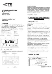
Option 3 - Analogue Outputs<br />
ANALOGUE INDICATOR (TREND)<br />
This module provides four d.c. isolated outputs.<br />
The 4-20mA output module must be powered from an external 24V d.c. source.<br />
Pin 16a = 0V<br />
Pin 16b = +24V<br />
The output signals are presented on pins 15a to 15d.<br />
See the output connection details for further clarification.<br />
These outputs can be individually assigned to represent any one of the measured and displayed<br />
parameters.<br />
All settings are user configurable via the user interface screens. See the customisation section<br />
for details.<br />
µp<br />
COUNTER<br />
Option 4 - Pulsed Outputs<br />
These modules supply pulses proportional to measured power.<br />
TYPICAL APPLICATION<br />
DATA COLLECTION<br />
INTEGRA <strong>2000</strong> can be configured via options to two pulsed outputs. Outputs are relays which<br />
are fully isolated, volt free contacts.<br />
Both relays are user definable to any of the hours related energy parameters e.g. Wh, VArh, VAh<br />
and Ah.<br />
The pulse width and rate are both user definable via the user interface screens.<br />
See the customisation section for details.<br />
Connection is made via a port screw clamp connector capable at accepting 2.5mm 2 cable.<br />
32
Output Connection Details<br />
Analogue Outputs - 4-20mA<br />
16 a 15 a 15 b 15 c 15 d 16 b<br />
0V OP1 OP2 OP3 OP4 24V<br />
- +1 +2 +3 +4 +24V<br />
Relay<br />
21 24 25 28<br />
Com N/O Com N/O<br />
RLA2 RLA1<br />
RS485<br />
31 32 33<br />
B A Gnd<br />
33
Appendix A<br />
Maximum Demand Calculation<br />
The maximum power consumption of an installation is an important measurement as most<br />
power utilities base their charges on it. Many utilities use a thermal maximum demand indicator<br />
(MDI) to measure this peak power consumption. An MDI averages the power consumed over a<br />
number of minutes, such that short surges do not give an artificially high reading.<br />
Integra <strong>2000</strong> uses a sliding window algorithm to simulate the characteristics of a thermal MDI<br />
instrument. As many different time constants are in use by the different power utilities, Integra<br />
<strong>2000</strong> can be configured to conform to any desired demand response.<br />
The demand period is made up of a number of sub-intervals. Each sub-interval can be between<br />
1 and 30 minutes duration. There can be between 1 and 30 sub-intervals in one demand period.<br />
For example, a 15 minute demand period may be represented as 1x15 minutes,<br />
3 x 5 minutes or 5 x 3 minutes. For each of these cases, the demand value will be updated every<br />
15, 5 or 3 minutes respectively.<br />
When the demand period is reset, the values in the Demand and Maximum Demand registers<br />
are set to zero. The Demand screen will show “TIMING” during the first demand period, as the<br />
values are misleading until the sliding window has been filled with valid readings. The display<br />
shows how many sub-intervals have been selected, and how many have elapsed. Once valid<br />
readings are being shown, the display counts through each sub-interval in Seconds.<br />
The length of each sub-interval and the number of them may be altered via the RS485 port using<br />
the MODBUS protocol. The demand period can also be reset, which allows synchronisation to<br />
other equipment.<br />
Neutral Current Calculation<br />
The neutral current value is calculated from the sum of the three vector currents and is provided<br />
as an indication of the neutral current load and has a worst case accuracy tolerance of ±4% of<br />
end scale.<br />
34
Appendix B<br />
Product Specification<br />
INPUTS<br />
Voltage<br />
Current<br />
Frequency<br />
V maximum.<br />
Measuring Range 10 - 100%<br />
Range of use 5 - 120%<br />
5 amps (1A optional).<br />
Measuring Range 10 - 100%<br />
Range of use 5 - 120%<br />
45 to 66Hz<br />
Power Factor Range of use -1 / 0 / 1 / 0 /-1<br />
Overloads<br />
Burden<br />
OUTPUTS<br />
Digital<br />
Voltage<br />
2x overload, applied 10 times for 1 second at 10 second intervals.<br />
Max terminal voltage 600V<br />
Current 20x overload, applied 5 times for 1 secondat 5 minute intervals.<br />
Max continuous terminal current 6A<br />
Voltage Each phase 0.02VA<br />
Current Each phase 0.6VA<br />
Ports<br />
1 off - RS485<br />
Protocol<br />
Style<br />
Modbus® RTU<br />
3 way 2 part screw clamp<br />
Analogue 4 off - Linear 4-20mA dc into 0-500Ω<br />
Uni-directional<br />
Externally powered.<br />
24V d.c. (16V -27V)<br />
Style -<br />
6 way 2 part screw clamp<br />
Pulsed Type<br />
Relay<br />
SPNO<br />
Switching.<br />
100V dc 0.5A.<br />
Style<br />
2 part screw clamp.<br />
ISOLATION<br />
Input to Digital O/P. Fibre<br />
RS485<br />
Input to Analogue O/P.<br />
Input to Pulsed O/P.<br />
Digital O/P to Analogue O/P<br />
= Infinite.<br />
= 2.2kV.<br />
= 2.2kV<br />
= 2.2kV<br />
= Not Isolated.<br />
35
MAXIMUM OPERATING VOLTAGE (W.R.T. GROUND)<br />
Voltage inputs:<br />
Current inputs:<br />
Digital / Analogue outputs:<br />
Pulsed outputs:<br />
346V<br />
24V<br />
100V<br />
100V<br />
ACCURACY CLASS<br />
Voltage<br />
0.5% of reading ±4 Digits<br />
Current<br />
0.5% of reading ±4 Digits<br />
Power<br />
1.0% of reading ±4 Digits<br />
Frequency<br />
0.1% of mid freq. ±2 Digits<br />
Phase Angle/<br />
Power Factor<br />
1.0% of reading ±4 Digits<br />
Note: The accuracy of calculated line-line voltages in 4 wire units is dependant upon the phase<br />
angle between the voltages.<br />
Display update 1 per second. 80mS approx.<br />
Analogue O/P 1.5% of ES.<br />
Analogue update 1 per second.<br />
RS485 O/P<br />
As accuracies above.<br />
RS232 O/P<br />
RS232 O/P<br />
As accuracies above.<br />
Update 50ms Average, 200mS Maximum<br />
CLIMATIC<br />
Temperature: operating 0 / 50°C<br />
storage<br />
-20 /+65°C<br />
calibration 23°C<br />
Temperature Coefficent:<br />
±0.013%/°C<br />
Humidity:<br />
95% RH non condensing<br />
Enclosure Code:<br />
IP54<br />
AUXILIARY SUPPLY<br />
100 - 250 V AC/DC<br />
12 - 48 V DC (option)<br />
Burden<br />
Analogue output supply:<br />
6VA<br />
24V d.c. (16-27V), clean (transients limited to 20V<br />
peak) cable to be screened.<br />
36
STANDARDS AND APPROVALS<br />
Complies with the relevent parts of the following standards.<br />
Consult factory for approvals listing.<br />
Safety IEC 1010/BSEN 61010-1, UL1244, CSA 22-2 (General electrical and mechanical<br />
safety requirement) IEC 664, VDE 0110, PD 6499 (insulation on low<br />
voltage systems)<br />
Enclosure EN60529, IEC 529, BS5490, (IP ratings & Fixings) DIN 43700 (Housing)<br />
EMC Emmisions BS EN 50081/1 Immunity BS EN 50082/2<br />
Test Measuring circuit BSEN 60688, IEC 688<br />
Method Performance BS4889, IEC 359 BSEN 61036, IEC 1036 (kWh functionality)<br />
37
Notes
The Information contained in these installation instructions is for use only by installers trained to make electrical power installations and is intended<br />
to describe the correct method of installation for this product. However, Tyco Electronics has no control over the field conditions which influence<br />
product installation.<br />
It is the user's responsibility to determine the suitability of the installation method in the user's field conditions. Tyco Electronics' only obligations<br />
are those in Tyco Electronics' standard Conditions of Sale for this product and in no case will Tyco Electronics be liable for any other incidental,<br />
indirect or consequential damages arising from the use or misuse of the products. <strong>Crompton</strong> is a trade mark.<br />
Tyco Electronics UK Limited<br />
<strong>Crompton</strong> <strong>Instruments</strong><br />
Freebournes Road, Witham, Essex, CM8 3AH, UK<br />
Tel: +44 1376 509 509 Fax: +44 1376 509 511<br />
http://energy.tycoelectronics.com