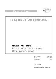
INSTRUCTION MANUAL
INSTRUCTION MANUAL
INSTRUCTION MANUAL

You also want an ePaper? Increase the reach of your titles
YUMPU automatically turns print PDFs into web optimized ePapers that Google loves.
I n t e r f a c e t e c h n i c<br />
<strong>INSTRUCTION</strong> <strong>MANUAL</strong><br />
IBRit-md2 / md2s / md2c<br />
Interface<br />
Document No. : D2F102 001<br />
Edition : January 2003<br />
© Copyright : IBR<br />
Messtechnik GmbH & Co. KG
Instruction Manual<br />
IBRit-md2/md2s/md2c<br />
Contents<br />
1. Introduction .................................................................................................................................... : 3<br />
2. Features .......................................................................................................................................... : 3<br />
3. Gauge connection table<br />
3.1 Gauge connection table of IBRit-md2 / md2c on the first three connectors ........................ : 4<br />
3.2 Gauge connection table of IBRit-md2s /md2c on the last three connectors ........................ : 6<br />
4. Delivered Items .............................................................................................................................. : 8<br />
5. Getting started ............................................................................................................................... : 8<br />
5.1 Self Check Routine ............................................................................................................... : 9<br />
6. Working with the IBRit-md2/-md2s/-md2c .................................................................................. : 10<br />
6.1 Starting installation of the ITEC-PC-Software under DOS.................................................... : 10<br />
6.2 Starting installation of the ITEC-PC-Software under WINDOWS ........................................ : 10<br />
7. Functions of the ITEC-PC-Software ............................................................................................. : 11<br />
7.1 Starting of the ITEC-PC-Software ........................................................................................ : 11<br />
7.2 Programme setup ................................................................................................................. : 11<br />
7.3 Test, Initialisation and Adjustment ....................................................................................... : 12<br />
7.3.1 Interface - Test ........................................................................................................... : 12<br />
7.3.2 Interface Initialisation ................................................................................................. : 12<br />
7.3.3 Help ............................................................................................................................ : 13<br />
8. Automatic initialisation with IBRSEND.EXE .............................................................................. : 13<br />
9. Simple check of the IBRit-interface ............................................................................................. : 14<br />
10. Programming and Controlling the interface ................................................................................ : 15<br />
10.1 Transmission format ............................................................................................................. : 15<br />
10.2 Data format of measured values ......................................................................................... : 15<br />
10.3 Summary of Command Set .................................................................................................. : 16<br />
10.4 Command responses ........................................................................................................... : 17<br />
10.5 Importing measured values into Windows applications ....................................................... : 17<br />
10.6 Importing measured values into MS-EXCEL ....................................................................... : 18<br />
11. Accessories and Order Information ............................................................................................. : 19<br />
12. Technical data ................................................................................................................................ : 19<br />
13. Pin assignments of connectors .................................................................................................... : 20<br />
14. Error solutions ................................................................................................................................ : 21<br />
15. Safety Instructions ......................................................................................................................... : 22<br />
16. Declaration of conformity .............................................................................................................. : 23<br />
17. Guarantee ........................................................................................................................................ : 23<br />
2
Instruction Manual<br />
IBRit-md2/md2s/md2c<br />
1. Introduction<br />
The universal gauge interfaces IBRit-md2, IBRit-md2s and IBRit-md2c with 6 gauge inputs enables<br />
you to connect different types of measuring instruments and gauges from different manufacturers<br />
to a PC or computer.<br />
Opto RS232, z.B. Sylvac, Mahr, Mauser, Helios...<br />
Tesa gauges<br />
Heidenhain counter<br />
Compac gauges<br />
Mitutoyo Digimatic gauges<br />
Mettler, Sartorius balances<br />
some gauges from<br />
Mecmesin, Erichsen, Kroeplin, Chatillon...<br />
For the gauges that cannot be connected directly by the original cables from the gauge manufacturers to<br />
the IBRit-md2/-md2s/-md2c there are several plug-adapters available.<br />
IBRit-md2<br />
IBRit-md2s<br />
IBRit-md2c<br />
: 6 Mitutoyo gauges<br />
: 6 Opto RS232 gauges<br />
: 3 Mitutoyo gauges<br />
3 Opto RS232 gauges<br />
2. Features<br />
Original cables of the gauge manufacturers can be plugged in directly or by plug adapters.<br />
Compact in size 163x42x92 mm at the desktop case and 149x43x97 mm at the disk rack case because of<br />
highly integrated circuits and SMD-technology.<br />
Connection to COM - Ports of your PC or to each RS232 - Connection<br />
Extensive command-set to control the data transfer.<br />
Conversation of the different gauge data formats to one standard data format<br />
Software is compatible to all IBRit-interfaces<br />
Request of measured values by software command, via data key on the gauge, permanent or via foot<br />
switch ( gauge assignment for foot switch request is software controlled ).<br />
An automatic data transfer from the gauge or a data transfer by data key on the gauge is only<br />
possible on the first channel and on all Mitutoyo inputs.<br />
3
Instruction Manual<br />
IBRit-md2/md2s/md2c<br />
3. Gauge connection table<br />
3.1 Gauge connection table of IBRit-md2 / md2c ( on md2c on the first three connectors )<br />
Gauge<br />
Manufacturer<br />
Gauge type<br />
Gauge<br />
output<br />
Handover<br />
Dre* Dtbg*<br />
IBR-cable<br />
adapter*<br />
Gauge<br />
connection<br />
cable*<br />
IBR<br />
Gauge<br />
driver*<br />
Mitutoyo<br />
Kroeplin<br />
Mecmessin<br />
Elektrophysik<br />
Erichsen<br />
Chatillon<br />
Mark<br />
Marposs<br />
All Digimatic<br />
Indicator EM25<br />
Gauge head ELI/ELO<br />
Gauge head EID/EOD<br />
Push/pull gauge MFG<br />
Push/pull gauge AFI,AFG,ATG<br />
Push/pull gauge AFG MKII<br />
Minitest 4100, 3100<br />
Minitest 2100, 1100<br />
Push-pull gauge 708<br />
Push-pull gauge DFGS50<br />
Push-pull gauge DFIS<br />
Forquetester Mark-10<br />
Marposs column<br />
Digimatic<br />
Digimatic<br />
Digimatic<br />
Digimatic<br />
Digimatic<br />
Digimatic<br />
Digimatic<br />
Digimatic<br />
Digimatic<br />
Digimatic<br />
Digimatic<br />
Digimatic<br />
Digimatic<br />
Digimatic<br />
YES<br />
YES<br />
YES<br />
YES<br />
YES<br />
YES<br />
YES<br />
YES<br />
YES<br />
YES<br />
YES<br />
YES<br />
YES<br />
YES<br />
n.a*<br />
YES<br />
YES<br />
---<br />
---<br />
---<br />
YES<br />
YES<br />
YES<br />
YES<br />
YES<br />
YES<br />
YES<br />
YES<br />
---<br />
---<br />
---<br />
---<br />
---<br />
---<br />
---<br />
---<br />
---<br />
---<br />
---<br />
---<br />
---<br />
---<br />
Mitutoyo<br />
Kroeplin<br />
Kroeplin<br />
Kroeplin<br />
IBR-F150 087<br />
IBR-F150 135<br />
IBR-F150 191<br />
Elektrophysik<br />
Elektrophysik<br />
IBR-F150 168<br />
IBR-F150 159<br />
IBR-F150 159<br />
Mark<br />
Marposs<br />
0041<br />
Sylvac<br />
TESA<br />
Mahr<br />
Bowers<br />
Caliper Opto RS232<br />
Caliper Opto RS232<br />
Indicator PM201,PM213<br />
Indicator 213<br />
Indicator 229<br />
Display D80<br />
Display D100S<br />
Micrometer S225/S235<br />
Micrometer Microcal<br />
Angle gauge S239<br />
Vertical gauge Z_CAL150/300<br />
Micrometer Micromaster<br />
Caliper Digit CAL, ETALON<br />
Indicator Digico 10/11/Min/Max<br />
Indicator Digico 20<br />
Vertical gauge Micro Hite 100<br />
Vertical g. Micro Hite 350/600/900<br />
Vertical gauge µ-Hite<br />
Vertical gauge Tesa Hite plus<br />
Vertical gauge ETALON ET1<br />
Vertical gauge ETALON EG<br />
Vertical gauge TESA TG-C10/C11<br />
Bore gauge IMICRO<br />
Column TT300<br />
Tesatronic TTD60<br />
Tesatronic TT10<br />
Tesatronic TT20 & TT60<br />
Indicator Millitast 1075<br />
Indicator Millitast 1082<br />
Indicator Millitast 1083/1085<br />
Indicator Extramess 2000/2001<br />
Bore gauge 44YE<br />
Vertical gauge DigimarM814N/G/Y<br />
Vertical gauge 27ES<br />
Micrometer 40EX/46EX<br />
Caliper 16EX/18EX/30EXN<br />
Caliper 30ESD/30ND<br />
Caliper 31ES/32ES<br />
Caliper 25ES<br />
Caliper BDC150X<br />
Caliper SNAPMIC Serie EIM<br />
Indicator Dialmatic Serie DI…<br />
Indicator Serie BDIL…/BDI…<br />
Depthmatic SerieEDG<br />
Millitron Serie CBAC<br />
BS Mark II Serie BSE…<br />
BS Holematic Serie SHM…<br />
Bore gauge Serie CBAC…<br />
Bore gauge MAG…<br />
Gauge head Serie TEA…/TLEA<br />
Opto RS Simplex<br />
Opto RS Duplex<br />
Opto RS Simplex<br />
Opto RS Duplex<br />
Opto RS Simplex<br />
Opto RS Simplex<br />
Opto RS Duplex<br />
Opto RS Simplex<br />
Opto RS Simplex<br />
Opto RS Duplex<br />
Opto RS Duplex<br />
Opto RS Simplex<br />
Opto RS Simplex<br />
Opto RS Simplex<br />
Opto RS Duplex<br />
Opto RS Duplex<br />
Opto RS Simplex<br />
Opto RS Duplex<br />
Opto RS Simplex<br />
Opto RS Simplex<br />
Opto RS Simplex<br />
Opto RS Duplex<br />
Opto RS Duplex<br />
Opto RS Simplex<br />
Opto RS Simplex<br />
Opto RS Simplex<br />
Opto RS Simplex<br />
Opto RS Simplex<br />
Opto RS Simplex<br />
Opto RS Simplex<br />
Opto RS Simplex<br />
Opto RS Simplex<br />
Opto RS Simplex<br />
Opto RS Simplex<br />
Opto RS Simplex<br />
Opto RS Simplex<br />
Opto RS Simplex<br />
Opto RS Simplex<br />
Opto RS Simplex<br />
Opto RS Simplex<br />
Opto RS Duplex<br />
Opto RS Duplex<br />
Opto RS Duplex<br />
Opto RS Duplex<br />
Opto RS Duplex<br />
Opto RS Duplex<br />
Opto RS Duplex<br />
Opto RS Simplex<br />
Opto RS Simplex<br />
Opto RS Simplex<br />
YES<br />
YES<br />
YES<br />
YES<br />
YES<br />
YES<br />
YES<br />
YES<br />
YES<br />
YES<br />
YES<br />
YES<br />
YES<br />
YES<br />
YES<br />
YES<br />
YES<br />
YES<br />
YES<br />
YES<br />
YES<br />
YES<br />
YES<br />
YES<br />
YES<br />
YES<br />
YES<br />
YES<br />
YES<br />
YES<br />
YES<br />
YES<br />
YES<br />
YES<br />
YES<br />
YES<br />
YES<br />
YES<br />
YES<br />
YES<br />
YES<br />
YES<br />
YES<br />
YES<br />
YES<br />
YES<br />
YES<br />
YES<br />
YES<br />
YES<br />
YES<br />
YES<br />
YES<br />
YES<br />
YES<br />
YES<br />
YES<br />
YES<br />
YES<br />
YES<br />
YES<br />
YES<br />
YES<br />
YES<br />
YES<br />
YES<br />
YES<br />
YES<br />
YES<br />
YES<br />
YES<br />
YES<br />
YES<br />
YES<br />
YES<br />
YES<br />
YES<br />
YES<br />
YES<br />
YES<br />
YES<br />
YES<br />
YES<br />
YES<br />
YES<br />
YES<br />
YES<br />
YES<br />
YES<br />
YES<br />
YES<br />
YES<br />
YES<br />
YES<br />
YES<br />
YES<br />
YES<br />
YES<br />
YES<br />
YES<br />
F152 175<br />
F152 247<br />
F152 175<br />
F152 247<br />
F152 175<br />
F152 175<br />
F152 247<br />
F152 175<br />
F152 175<br />
F152 247<br />
F152 247<br />
F152 175<br />
F152 175<br />
F152 175<br />
F152 247<br />
F152 247<br />
F152 175<br />
F152 247<br />
F152 175<br />
F152 175<br />
F152 175<br />
F152 247<br />
F152 247<br />
F152 175<br />
F152 175<br />
F152 175<br />
F152 175<br />
F152 175<br />
F152 175<br />
F152 175<br />
F152 175<br />
F152 175<br />
F152 175<br />
F152 175<br />
F152 175<br />
F152 175<br />
F152 175<br />
F152 175<br />
F152 175<br />
F152 175<br />
F152 247<br />
F152 247<br />
F152 247<br />
F152 247<br />
F152 247<br />
F152 247<br />
F152 247<br />
F152 175<br />
F152 175<br />
F152 175<br />
Sylvac 926.5521<br />
Sylvac 926.6521<br />
Sylvac 926.5521<br />
Sylvac 926.6521<br />
Sylvac 926.5521<br />
Sylvac 926.5521<br />
Sylvac 926.6521<br />
Sylvac 926.5521<br />
Sylvac 926.5521<br />
Sylvac 926.6521<br />
Sylvac 926.6521<br />
TESA 47.61046<br />
TESA 47.61046<br />
TESA 47.61046<br />
TESA 47.61049<br />
TESA 47.61052<br />
TESA 47.61046<br />
TESA 47.61052<br />
TESA 47.61046<br />
TESA 46.39008<br />
TESA 47.61023<br />
TESA 47.61052<br />
TESA 47.61049<br />
IBR-F150 244<br />
TESA 47.61023<br />
IBR-F150 174<br />
TESA 47.61046<br />
Mahr 410.2410<br />
Mahr 410.2510<br />
request Mahr<br />
Mahr 434.6020<br />
Mahr 410.2510<br />
Mahr 410.2510<br />
Mahr 410.2510<br />
Mahr 410.2410<br />
Mahr 410.2410<br />
Mahr 410.2510<br />
Mahr 410.2510<br />
Mahr 410.2410<br />
Sylvac 926.5521<br />
Sylvac 926.6521<br />
Sylvac 926.6521<br />
Sylvac 926.6521<br />
Sylvac 926.6521<br />
Sylvac 926.6521<br />
Sylvac 926.6521<br />
Sylvac 926.6521<br />
Sylvac 926.5521<br />
Sylvac 926.5521<br />
Sylvac 926.5521<br />
0901<br />
4
Instruction Manual<br />
IBRit-md2/md2s/md2c<br />
Gauge<br />
Manufacturer<br />
Gauge type<br />
Gauge<br />
output<br />
Handover<br />
Dre* Dtbg*<br />
IBR-cable<br />
adapter*<br />
Gauge<br />
connection<br />
cable *<br />
IBR<br />
Gauge<br />
driver*<br />
IBR<br />
Cary<br />
Diatest<br />
Blankenhorn<br />
Mauser<br />
Helios<br />
Trimos<br />
Column C100<br />
Digital gauge B100<br />
Indicator cary shop<br />
Digitron<br />
Caliper dico<br />
Indicator<br />
Caliper Opto RS<br />
Indicator Opto RS<br />
Bore gauge Matic integral<br />
Bore gauge Matic Uhr<br />
Vertical gauge TVM301/601<br />
Opto RS Simplex<br />
Opto RS Simplex<br />
Opto RS Simplex<br />
Opto RS Simplex<br />
Opto RS Simplex<br />
Opto RS Simplex<br />
Opto RS Simplex<br />
Opto RS Duplex<br />
Opto RS Simplex<br />
Opto RS Simplex<br />
Opto RS Duplex<br />
YES<br />
YES<br />
YES<br />
YES<br />
YES<br />
YES<br />
YES<br />
YES<br />
YES<br />
YES<br />
YES<br />
YES<br />
YES<br />
YES<br />
YES<br />
YES<br />
YES<br />
YES<br />
YES<br />
YES<br />
YES<br />
YES<br />
F152 175<br />
F152 175<br />
F152 175<br />
F152 175<br />
F152 175<br />
F152 175<br />
F152 175<br />
F152 247<br />
F152 175<br />
F152 175<br />
F152 175<br />
IBR-F150 210<br />
IBR-F150 210<br />
Sylvac 926.5521<br />
Sylvac 926.5521<br />
Sylvac 926.5521<br />
Sylvac 926.5521<br />
Sylvac 926.5521<br />
Sylvac 926.6521<br />
Sylvac 926.5521<br />
Sylvac 926.5521<br />
Sylvac 926.6521<br />
0901<br />
TESA<br />
Compac<br />
Mauser<br />
Wolpert<br />
Micrometer Tesadigit<br />
Caliper Digit-Cal SI/SM<br />
Indicator Digico 1 / 2<br />
Micro Hite02/04<br />
Micro Hite 06<br />
Bore gauge Triomatic<br />
Indicator Mesco<br />
Caliper Digital 2<br />
Indicator Digico<br />
Pseudo RS<br />
Pseudo RS<br />
Pseudo RS<br />
Pseudo RS<br />
Pseudo RS<br />
Pseudo RS<br />
Pseudo RS<br />
Opto RS Simplex<br />
Pseudo RS<br />
YES<br />
YES<br />
YES<br />
YES<br />
YES<br />
YES<br />
YES<br />
YES<br />
YES<br />
YES<br />
YES<br />
YES<br />
YES<br />
YES<br />
YES<br />
YES<br />
YES<br />
YES<br />
F152 179<br />
F152 179<br />
F152 179<br />
F152 179<br />
F152 176<br />
F152 179<br />
F152 179<br />
F152 175<br />
F152 179<br />
TESA 06.000009<br />
TESA 49.60006<br />
TESA S47.9012<br />
TESA S60.60002<br />
IBR-F150 077<br />
TESA 60.60002<br />
IBR-F150 144<br />
Sylvac 926.5521<br />
TESA S47.9012<br />
0181<br />
Mettler Option 11<br />
Option 12<br />
Option 82<br />
Option 03,05<br />
Option 16, unidirectional<br />
Option 18<br />
Data PacM, AT-balances<br />
PG-balances, MT-SICS (CAN Bus)<br />
PG-balances, MT-SICS (RS232)<br />
Balances PM, AM, SM<br />
Balances PJ<br />
Balances PC, AC Option 03<br />
Balances CL Interface<br />
RS232<br />
RS232<br />
RS232<br />
RS232<br />
RS232<br />
RS232<br />
RS232<br />
CAN-Bus<br />
RS232<br />
RS232<br />
RS232<br />
RS232<br />
RS232<br />
---<br />
YES<br />
YES<br />
YES<br />
---<br />
YES<br />
YES<br />
YES<br />
YES<br />
YES<br />
YES<br />
YES<br />
YES<br />
YES<br />
YES<br />
YES<br />
YES<br />
YES<br />
YES<br />
YES<br />
YES<br />
YES<br />
YES<br />
YES<br />
YES<br />
YES<br />
F152 176<br />
F152 176<br />
F152 176<br />
F152 176<br />
F152 176<br />
F152 176<br />
F152 176<br />
F152 176<br />
F152 176<br />
F152 176<br />
F152 176<br />
F152 176<br />
F152 176<br />
IBR-F150 054<br />
IBR-F150 054<br />
IBR-F150 104<br />
IBR-F150 091<br />
IBR-F150 029<br />
IBR-F150 029<br />
IBR-F150 029<br />
IBR-F150 169<br />
IBR-F150 217<br />
IBR-F150 029<br />
IBR-F150 029<br />
IBR-F150 091<br />
IBR-F150 140<br />
0211<br />
Sartorius<br />
Balances MP8-4, MP8-4 plus, mc1<br />
Balances MP8, MP8-1, MP8-2,<br />
Balances MP6, BL3100<br />
RS232 counter 705317<br />
Balances A200-S, E1200S<br />
Balances BP-/U-/I-/F-/A-/L-Serie<br />
Balance Basic Plus<br />
Balance QS4000/QS8000<br />
Balance QS16000<br />
RS232<br />
RS232<br />
RS232<br />
RS232<br />
RS232<br />
RS232<br />
RS232<br />
RS232<br />
RS232<br />
YES<br />
YES<br />
YES<br />
YES<br />
YES<br />
YES<br />
YES<br />
YES<br />
YES<br />
YES<br />
YES<br />
YES<br />
YES<br />
YES<br />
YES<br />
YES<br />
YES<br />
YES<br />
F152 176<br />
F152 176<br />
F152 176<br />
F152 176<br />
F152 176<br />
F152 176<br />
F152 176<br />
F152 176<br />
F152 176<br />
IBR-F150 094<br />
IBR-F150 094<br />
IBR-F150 094<br />
IBR-F150 094<br />
IBR-F150 094<br />
IBR-F150 094<br />
IBR-F150 094<br />
IBR-F150 094<br />
IBR-F150 094<br />
0441<br />
Heidenhain VRZ 210, ND 291<br />
VRZ 480, 403, ND 281<br />
VRZ 403, VD281<br />
VRZ 405, 406<br />
VRZ 720B,760B,ND920,ND960<br />
VRZ 735, 775<br />
Positip 850<br />
ND 221, ND 261<br />
RS232<br />
RS232<br />
RS232<br />
RS232<br />
RS232<br />
RS232<br />
RS232<br />
RS232<br />
YES<br />
YES<br />
YES<br />
YES<br />
YES<br />
YES<br />
YES<br />
YES<br />
---<br />
---<br />
---<br />
---<br />
---<br />
---<br />
---<br />
---<br />
F152 176<br />
F152 176<br />
F152 176<br />
F152 176<br />
F152 176<br />
F152 176<br />
F152 176<br />
F152 176<br />
IBR-F150 063<br />
IBR-F150 063<br />
IBR-F150 063<br />
IBR-F150 063<br />
IBR-F150 063<br />
IBR-F150 063<br />
IBR-F150 063<br />
IBR-F150 063<br />
0451<br />
TESA Hite Opto RS Simplex YES YES F152 175 TESA 47.61046 1371<br />
Dre*<br />
: Option of external measurement data request by foot or hand-switch, software-command<br />
( Data request extern ) ( DAS ) or permanent request by software-command ( DAP )<br />
Dtbg*<br />
: Option of measurement data output control by the gauge. Data output triggered by a<br />
( Data trigger by gauge ) button on the gauge or automatically on end of a measurement cycle.<br />
n.a.*<br />
: Not available on all gauges.<br />
IBR cable adapter*<br />
: IBR-order number. The gauge connection cable requires an adapter if there is a number.<br />
Gauge connection cable * : Manufacturer of the cable and order number or connection type.<br />
IBR gauge driver *<br />
: The driver-number address of the programme module in the library for the different gauge<br />
types.<br />
5
Instruction Manual<br />
IBRit-md2/md2s/md2c<br />
3.2 Gauge connection table of IBRit-md2s / md2c ( on md2c on the last three connectors )<br />
Gauge<br />
Manufacturer<br />
Gauge type<br />
Gauge<br />
output<br />
Handover<br />
Dre* Dtbg*<br />
IBR-cable<br />
adapter*<br />
Gauge<br />
connection<br />
cable*<br />
IBR<br />
Gauge<br />
driver*<br />
Sylvac<br />
TESA<br />
Trimos<br />
Mahr<br />
Helios<br />
Bowers<br />
IBR<br />
Cary<br />
Diatest<br />
Blankenhorn<br />
Mauser<br />
Caliper Opto RS232<br />
Caliper Opto RS232<br />
Indicator PM201,PM213<br />
Indicator 213<br />
Indicator 229<br />
Display D80<br />
Display D100S<br />
Micrometer S225/S235<br />
Micrometer Microcal<br />
Angle gauge S239<br />
Vertical gauge Z_CAL150/300<br />
Micrometer Micromaster<br />
Caliper Digit CAL, ETALON<br />
Indicator Digico 10/11/Min/Max<br />
Indicator Digico 20<br />
Vertical gauge Micro Hite 100<br />
Vertical g. Micro Hite 350/600/900<br />
Vertical gauge µ-Hite<br />
Vertical gauge Tesa Hite plus<br />
Vertical gauge ETALON ET1<br />
Vertical gauge ETALON EG<br />
Vertical gauge TESA TG-C10/C11<br />
Bore gauge IMICRO<br />
Column TT300<br />
Tesatronic TTD60<br />
Tesatronic TT10<br />
Tesatronic TT20 & TT60<br />
Vertical gauge TVM 301/601<br />
Indicator Millitast 1075<br />
Indicator Millitast 1082<br />
Indicator Millitast 1083/1085<br />
Indicator Extramess 2000/2001<br />
Bore gauge 44YE<br />
Vertical gauge DigimarM814N/G/Y<br />
Vertical gauge 27ES<br />
Micrometer 40EX/46EX<br />
Caliper 16EX/18EX/30EXN<br />
Caliper 30ESD/30ND<br />
Caliper 31ES/32ES<br />
Caliper 25ES<br />
Caliper Opto RS<br />
Indicator Opto RS<br />
Bore gauge Matic integral<br />
Bore gauge Matic Uhr<br />
Caliper BDC150X<br />
Caliper SNAPMIC Serie EIM<br />
Indicator Dialmatic Serie DI…<br />
Indicator Serie BDIL…/BDI…<br />
Depthmatic SerieEDG<br />
Millitron Serie CBAC<br />
BS Mark II Serie BSE…<br />
BS Holematic Serie SHM…<br />
Bore gauge Serie CBAC…<br />
Bore gauge MAG…<br />
Gauge head Serie TEA…/TLEA<br />
Column C100<br />
Digital gauge B100<br />
Indicator cary shop<br />
Digitron<br />
Caliper dico<br />
Indicator<br />
Opto RS Simplex<br />
Opto RS Duplex<br />
Opto RS Simplex<br />
Opto RS Duplex<br />
Opto RS Simplex<br />
Opto RS Simplex<br />
Opto RS Duplex<br />
Opto RS Simplex<br />
Opto RS Simplex<br />
Opto RS Duplex<br />
Opto RS Duplex<br />
Opto RS Simplex<br />
Opto RS Simplex<br />
Opto RS Simplex<br />
Opto RS Duplex<br />
Opto RS Duplex<br />
Opto RS Simplex<br />
Opto RS Duplex<br />
Opto RS Simplex<br />
Opto RS Simplex<br />
Opto RS Simplex<br />
Opto RS Duplex<br />
Opto RS Duplex<br />
Opto RS Simplex<br />
Opto RS Simplex<br />
Opto RS Simplex<br />
Opto RS Simplex<br />
Opto RS Duplex<br />
Opto RS Simplex<br />
Opto RS Simplex<br />
Opto RS Simplex<br />
Opto RS Simplex<br />
Opto RS Simplex<br />
Opto RS Simplex<br />
Opto RS Simplex<br />
Opto RS Simplex<br />
Opto RS Simplex<br />
Opto RS Simplex<br />
Opto RS Simplex<br />
Opto RS Simplex<br />
Opto RS Simplex<br />
Opto RS Duplex<br />
Opto RS Simplex<br />
Opto RS Simplex<br />
Opto RS Simplex<br />
Opto RS Duplex<br />
Opto RS Duplex<br />
Opto RS Duplex<br />
Opto RS Duplex<br />
Opto RS Duplex<br />
Opto RS Duplex<br />
Opto RS Duplex<br />
Opto RS Simplex<br />
Opto RS Simplex<br />
Opto RS Simplex<br />
Opto RS Simplex<br />
Opto RS Simplex<br />
Opto RS Simplex<br />
Opto RS Simplex<br />
Opto RS Simplex<br />
Opto RS Simplex<br />
YES<br />
YES<br />
YES<br />
YES<br />
YES<br />
YES<br />
YES<br />
YES<br />
YES<br />
YES<br />
YES<br />
YES<br />
YES<br />
YES<br />
YES<br />
YES<br />
YES<br />
YES<br />
YES<br />
YES<br />
YES<br />
YES<br />
YES<br />
YES<br />
YES<br />
YES<br />
YES<br />
YES<br />
YES<br />
YES<br />
YES<br />
YES<br />
YES<br />
YES<br />
YES<br />
YES<br />
YES<br />
YES<br />
YES<br />
YES<br />
YES<br />
YES<br />
YES<br />
YES<br />
YES<br />
YES<br />
YES<br />
YES<br />
YES<br />
YES<br />
YES<br />
YES<br />
YES<br />
YES<br />
YES<br />
YES<br />
YES<br />
YES<br />
YES<br />
YES<br />
YES<br />
YES<br />
YES<br />
YES<br />
YES<br />
YES<br />
YES<br />
YES<br />
YES<br />
YES<br />
YES<br />
YES<br />
YES<br />
YES<br />
YES<br />
YES<br />
YES<br />
YES<br />
YES<br />
YES<br />
YES<br />
YES<br />
YES<br />
YES<br />
YES<br />
YES<br />
YES<br />
YES<br />
YES<br />
YES<br />
YES<br />
YES<br />
YES<br />
YES<br />
YES<br />
YES<br />
YES<br />
YES<br />
YES<br />
YES<br />
YES<br />
YES<br />
YES<br />
YES<br />
YES<br />
YES<br />
YES<br />
YES<br />
YES<br />
YES<br />
YES<br />
YES<br />
YES<br />
YES<br />
YES<br />
YES<br />
YES<br />
YES<br />
YES<br />
YES<br />
YES<br />
YES<br />
---<br />
F152 245<br />
---<br />
F152 245<br />
---<br />
---<br />
F152 245<br />
---<br />
---<br />
F152 245<br />
F152 245<br />
---<br />
---<br />
---<br />
F152 245<br />
F152 245<br />
---<br />
F152 245<br />
---<br />
---<br />
---<br />
F152 245<br />
F152 245<br />
---<br />
---<br />
---<br />
---<br />
---<br />
---<br />
---<br />
---<br />
---<br />
---<br />
---<br />
---<br />
---<br />
---<br />
---<br />
---<br />
---<br />
---<br />
F152 245<br />
---<br />
---<br />
---<br />
F152 245<br />
F152 245<br />
F152 245<br />
F152 245<br />
F152 245<br />
F152 245<br />
F152 245<br />
---<br />
---<br />
---<br />
---<br />
---<br />
---<br />
---<br />
---<br />
---<br />
Sylvac 926.5521<br />
Sylvac 926.6521<br />
Sylvac 926.5521<br />
Sylvac 926.6521<br />
Sylvac 926.5521<br />
Sylvac 926.5521<br />
Sylvac 926.6521<br />
Sylvac 926.5521<br />
Sylvac 926.5521<br />
Sylvac 926.6521<br />
Sylvac 926.6521<br />
TESA 47.61046<br />
TESA 47.61046<br />
TESA 47.61046<br />
TESA 47.61049<br />
TESA 47.61052<br />
TESA 47.61046<br />
TESA 47.61052<br />
TESA 47.61046<br />
TESA 46.39008<br />
TESA 47.61023<br />
TESA 47.61052<br />
TESA 47.61049<br />
IBR-F150 244<br />
TESA 47.61023<br />
IBR-F150 174<br />
TESA 47.61046<br />
Sylvac 926.6521<br />
Mahr 410.2410<br />
Mahr 410.2510<br />
request Mahr<br />
Mahr 434.6020<br />
Mahr 410.2510<br />
Mahr 410.2510<br />
Mahr 410.2510<br />
Mahr 410.2410<br />
Mahr 410.2410<br />
Mahr 410.2510<br />
Mahr 410.2510<br />
Mahr 410.2410<br />
Sylvac 926.5521<br />
Sylvac 926.6521<br />
Sylvac 926.5521<br />
Sylvac 926.5521<br />
Sylvac 926.5521<br />
Sylvac 926.6521<br />
Sylvac 926.6521<br />
Sylvac 926.6521<br />
Sylvac 926.6521<br />
Sylvac 926.6521<br />
Sylvac 926.6521<br />
Sylvac 926.6521<br />
Sylvac 926.5521<br />
Sylvac 926.5521<br />
Sylvac 926.5521<br />
IBR-F150 210<br />
IBR-F150 210<br />
Sylvac 926.5521<br />
Sylvac 926.5521<br />
Sylvac 926.5521<br />
Sylvac 926.5521<br />
0901<br />
TESA Hite Opto RS Simplex YES YES --- TESA 47.61046 1371<br />
6
Instruction Manual<br />
IBRit-md2/md2s/md2c<br />
Gauge<br />
Manufacturer<br />
Gauge type<br />
Gauge<br />
output<br />
Handover<br />
Dre* Dtbg*<br />
IBR-cable<br />
adapter*<br />
Gauge<br />
connection<br />
cable *<br />
IBR<br />
Gauge<br />
driver*<br />
Compac<br />
Mauser<br />
Wolpert<br />
TESA<br />
Indicator Mesco<br />
Caliper Digital 2<br />
Indicator Digico<br />
Micrometer Tesadigit<br />
Caliper Digit-Cal SI/SM<br />
Indicator Digico 1 / 2<br />
Micro Hite02/04<br />
Micro Hite 06<br />
Bore gauge Triomatic<br />
Pseudo RS<br />
Opto RS Simplex<br />
Pseudo RS<br />
Pseudo RS<br />
Pseudo RS<br />
Pseudo RS<br />
Pseudo RS<br />
Pseudo RS<br />
Pseudo RS<br />
YES<br />
YES<br />
YES<br />
YES<br />
YES<br />
YES<br />
YES<br />
YES<br />
YES<br />
YES<br />
YES<br />
YES<br />
YES<br />
YES<br />
YES<br />
YES<br />
YES<br />
YES<br />
F152 180<br />
---<br />
F152 180<br />
F152 180<br />
F152 180<br />
F152 180<br />
F152 180<br />
F152 178<br />
F152 180<br />
IBR-F150 144<br />
Sylvac 926.5521<br />
TESA S47.9012<br />
TESA 06.000009<br />
TESA 49.60006<br />
TESA S47.9012<br />
TESA S60.60002<br />
IBR-F150 077<br />
TESA 60.60002<br />
0181<br />
Mitutoyo<br />
Kroeplin<br />
Mecmessin<br />
Elektrophysik<br />
Erichsen<br />
Chatillon<br />
Mark<br />
Marposs<br />
All Digimatic<br />
Indicator EM25<br />
Gauge head ELI/ELO<br />
Gauge head EID/EOD<br />
Push/pull gauge MFG<br />
Push/pull gauge AFI,AFG,ATG<br />
Push/pull gauge AFG MKII<br />
Minitest 4100, 3100<br />
Minitest 2100, 1100<br />
Push-pull gauge 708<br />
Push-pull gauge DFGS50<br />
Push-pull gauge DFIS<br />
Forquetester Mark-10<br />
Marposs column<br />
Digimatic<br />
Digimatic<br />
Digimatic<br />
Digimatic<br />
Digimatic<br />
Digimatic<br />
Digimatic<br />
Digimatic<br />
Digimatic<br />
Digimatic<br />
Digimatic<br />
Digimatic<br />
Digimatic<br />
Digimatic<br />
YES<br />
YES<br />
YES<br />
YES<br />
YES<br />
YES<br />
YES<br />
YES<br />
YES<br />
YES<br />
YES<br />
YES<br />
YES<br />
YES<br />
n.a*<br />
YES<br />
YES<br />
---<br />
---<br />
---<br />
YES<br />
YES<br />
YES<br />
YES<br />
YES<br />
YES<br />
YES<br />
YES<br />
F152 177<br />
F152 177<br />
F152 177<br />
F152 177<br />
F152 177<br />
F152 177<br />
F152 177<br />
F152 177<br />
F152 177<br />
F152 177<br />
F152 177<br />
F152 177<br />
F152 177<br />
F152 177<br />
Mitutoyo<br />
Kroeplin<br />
Kroeplin<br />
Kroeplin<br />
IBR-F150 087<br />
IBR-F150 135<br />
IBR-F150 191<br />
Elektrophysik<br />
Elektrophysik<br />
IBR-F150 168<br />
IBR-F150 159<br />
IBR-F150 159<br />
Mark<br />
Marposs<br />
0041<br />
Mettler Option 11<br />
Option 12<br />
Option 82<br />
Option 03,05<br />
Option 16, unidirectional<br />
Option 18<br />
Data PacM, AT-balances<br />
PG-balances, MT-SICS (CAN Bus)<br />
PG-balances, MT-SICS (RS232)<br />
Balances PM, AM, SM<br />
Balances PJ<br />
Balances PC, AC Option 03<br />
Balances CL Interface<br />
RS232<br />
RS232<br />
RS232<br />
RS232<br />
RS232<br />
RS232<br />
RS232<br />
CAN-Bus<br />
RS232<br />
RS232<br />
RS232<br />
RS232<br />
RS232<br />
---<br />
YES<br />
YES<br />
YES<br />
---<br />
YES<br />
YES<br />
YES<br />
YES<br />
YES<br />
YES<br />
YES<br />
YES<br />
YES<br />
YES<br />
YES<br />
YES<br />
YES<br />
YES<br />
YES<br />
YES<br />
YES<br />
YES<br />
YES<br />
YES<br />
YES<br />
F152 178<br />
F152 178<br />
F152 178<br />
F152 178<br />
F152 178<br />
F152 178<br />
F152 178<br />
F152 178<br />
F152 178<br />
F152 178<br />
F152 178<br />
F152 178<br />
F152 178<br />
IBR-F150 054<br />
IBR-F150 054<br />
IBR-F150 104<br />
IBR-F150 091<br />
IBR-F150 029<br />
IBR-F150 029<br />
IBR-F150 029<br />
IBR-F150 169<br />
IBR-F150 217<br />
IBR-F150 029<br />
IBR-F150 029<br />
IBR-F150 091<br />
IBR-F150 140<br />
0211<br />
Sartorius<br />
Balances MP8-4, MP8-4 plus, mc1<br />
Balances MP8, MP8-1, MP8-2,<br />
Balances MP6, BL3100<br />
RS232 counter 705317<br />
Balances A200-S, E1200S<br />
Balances BP-/U-/I-/F-/A-/L-Serie<br />
Balance Basic Plus<br />
Balance QS4000/QS8000<br />
Balance QS16000<br />
RS232<br />
RS232<br />
RS232<br />
RS232<br />
RS232<br />
RS232<br />
RS232<br />
RS232<br />
RS232<br />
YES<br />
YES<br />
YES<br />
YES<br />
YES<br />
YES<br />
YES<br />
YES<br />
YES<br />
YES<br />
YES<br />
YES<br />
YES<br />
YES<br />
YES<br />
YES<br />
YES<br />
YES<br />
F152 178<br />
F152 178<br />
F152 178<br />
F152 178<br />
F152 178<br />
F152 178<br />
F152 178<br />
F152 178<br />
F152 178<br />
IBR-F150 094<br />
IBR-F150 094<br />
IBR-F150 094<br />
IBR-F150 094<br />
IBR-F150 094<br />
IBR-F150 094<br />
IBR-F150 094<br />
IBR-F150 094<br />
IBR-F150 094<br />
0441<br />
Heidenhain VRZ 210, ND 291<br />
VRZ 480, 403, ND 281<br />
VRZ 403, VD281<br />
VRZ 405, 406<br />
VRZ 720B,760B,ND920,ND960<br />
VRZ 735, 775<br />
Positip 850<br />
ND 221, ND 261<br />
RS232<br />
RS232<br />
RS232<br />
RS232<br />
RS232<br />
RS232<br />
RS232<br />
RS232<br />
YES<br />
YES<br />
YES<br />
YES<br />
YES<br />
YES<br />
YES<br />
YES<br />
---<br />
---<br />
---<br />
---<br />
---<br />
---<br />
---<br />
---<br />
F152 178<br />
F152 178<br />
F152 178<br />
F152 178<br />
F152 178<br />
F152 178<br />
F152 178<br />
F152 178<br />
IBR-F150 063<br />
IBR-F150 063<br />
IBR-F150 063<br />
IBR-F150 063<br />
IBR-F150 063<br />
IBR-F150 063<br />
IBR-F150 063<br />
IBR-F150 063<br />
0451<br />
Dre*<br />
: Option of external measurement data request by foot or hand-switch, software-command<br />
( Data request extern ) ( DAS ) or permanent request by software-command ( DAP )<br />
Dtbg*<br />
: Option of measurement data output control by the gauge. Data output triggered by a<br />
( Data trigger by gauge ) button on the gauge or automatically on end of a measurement cycle.<br />
n.a.*<br />
: Not available on all gauges.<br />
IBR cable adapter*<br />
: IBR-order number. The gauge connection cable requires an adapter if there is a number.<br />
Gauge connection cable * : Manufacturer of the cable and order number or connection type.<br />
IBR gauge driver *<br />
: The driver-number address of the programme module in the library for the different gauge<br />
types.<br />
7
Instruction Manual<br />
IBRit-md2/md2s/md2c<br />
4. Delivered Items<br />
Delivered Items of a desk top Instrument :<br />
IBRit-md2/-md2s/-md2c includes plug in power-source, operating manual and software.<br />
For additional accessories like foot switch, hand switch,... please refer to the delivery note.<br />
Please check that the delivery contains all items and retain the packaging box.<br />
5. Getting started<br />
1. Connecting to the PC or Computer<br />
Plug the RS232 data cable into the PC serial port and the RS232 socket on the IBRit-md2/-md2s/-<br />
md2c-bt rear panel.<br />
The transmission format of the RS232 interface is set fix to 9600 Baud, no parity, 8 Data bits and 1 stop<br />
bit.<br />
2. External Trigger Switch<br />
Connect the foot switch or press switch to the TRIGGER socket on the rear panel of the IBRit-md2/-<br />
md2s/-md2c-bt.<br />
3. Connecting to the Mains<br />
Connect the plug-in power source to the socket AC on the rear panel of the IBRit-md2/-md2s/-md2cbt.<br />
Use only the delivered plug-in power source. Check the supply voltage before connecting the plugin<br />
source to the mains. Note the type plate of the plug-in power source.<br />
4. Connecting Gauges<br />
Connect the gauges to the IBRit-md2/-md2s/-md2c-bt according to your measurement application.<br />
Therefore switch off the gauges and the interface before. Note the necessary settings of the gauges to<br />
transfer measured values.<br />
5. Switching on<br />
Switch on the supply and the power-on lamp illuminates. The IBRit-md2/-md2s/-md2c-bt enters a self<br />
check routine. If no errors are detected the IT-lamp shows 4 short flashes and the system is ready for<br />
work. If errors are detected they are signalled with a sequence of long and short flashes.<br />
The table on page 9 shows the meanings of the flash sequences.<br />
8
Instruction Manual<br />
IBRit-md2/md2s/md2c<br />
5.1 Self Check Routine<br />
The IBRit-md2/-md2s/-md2c self check routine is invoked at power-on and on receipt of a RESET<br />
command. All system components are checked. The test result is signalled by the IT-lamp on the rear<br />
panel. Four short flashes indicate no errors were found. A sequences of long and short flashes indicate<br />
errors. The table gives the meanings of the error signals. The IBRit-md2/-md2s/-md2c remains in the self<br />
test mode until the fault is cleared and cannot be used for gauging. The self-check cycle takes 3 to 4<br />
seconds.<br />
Self-check Error Flash Sequence :<br />
-------------------------------------------------------------------------------------------------------------------------------------<br />
Test result : Flash sequence : Error :<br />
-------------------------------------------------------------------------------------------------------------------------------------<br />
--- S S S S No errors detected, self-check complete<br />
Error 1 L S S S Error in programme memory<br />
Error 2 S L S S Error in working memory<br />
Notice : S - short flash ( 0,5 seconds )<br />
L - long flash ( 1 second )<br />
9
Instruction Manual<br />
IBRit-md2/md2s/md2c<br />
6. Working with the IBRit-md2/-md2s/-md2c<br />
The IBRit-md2/-md2s/md2c incorporates an extensive command set to realise various<br />
measurement applications and to setup the interface.<br />
The manual includes a 3,5“-floppy disk containing the PC software.<br />
This software is necessary to :<br />
Make, edit and send a initialisation to the IBRit-md2/-md2s/-md2c<br />
Test the initialisation / read measured values<br />
Transfer a initialisation automatically to the IBRit-md2/-md2s/-md2c<br />
The following section explains the installation of the software and gives a survey of the<br />
programme-features.<br />
6.1 Starting installation of the ITEC-PC-Software under DOS<br />
1. Insert the floppy disc into the floppy drive of your computer<br />
2. Select this drive with i.e. A: <br />
3. Type INSTALL to start the installation<br />
6.2 Starting installation of the ITEC-PC-Software under WINDOWS<br />
1. Start Windows 3.xx or a 32-Bit Windows version ( Windows 95, 98, ME, NT, XP, … )<br />
2. Insert the floppy disc into the floppy drive of your computer<br />
3. Start file-manager ( Windows 3.xx ) or windows explorer ( Windows 95, 98, … )<br />
4. Select the drive containing the floppy<br />
5. Select the programme INSTALL<br />
6. Go to Menu File and select Open<br />
Running the installation<br />
The installation programme first asks for the destination drive and directory where it will place the software<br />
files. Either confirm the suggested directory, C:\IBRit, or type in an alternative directory name and path.<br />
Pressing the -key creates the new directory and starts the installation of the files. At the end of<br />
installation the computer automatically change to the new directory and starts the programme ITEC.EXE.<br />
The installed software is self explanatory and needs no additional manual. The software essentially<br />
consists of following programmes :<br />
ITEC.EXE<br />
Programme to setup and test the IBR interface device. This setup, also named initialisation, can be stored<br />
on the computer.<br />
IBRSEND.EXE<br />
Programme to transfer a initialisation ( created with ITEC ) automatically to the IBRit interface device.<br />
10
Instruction Manual<br />
IBRit-md2/md2s/md2c<br />
7. Functions of the ITEC-PC-Software<br />
The ITEC-PC-Software is an universal programme for testing, calibrating and setting of all IBRit<br />
interfaces and measuring instruments. Designed to SAA-standards the programme can select<br />
different language versions.<br />
The user is led through the programme by a menu bar at the top of the screen. By selecting these<br />
menu items, windows open leading on to other software function. Easy to follow text in the<br />
windows explains every user function.<br />
Every screen lists the possible key functions along the bottom line ( hotkeys ).<br />
7.1 Starting the ITEC-PC-Software<br />
Windows : Please start the Windows Explorer and change to the folder which you have entered on the<br />
installation ( i.e. : C:\IBRit ). Select the application ITEC.EXE and start it with the menu : File /<br />
Open.<br />
MS-DOS : Change at first to the directory ( i.e. with the command cd IBRit ). After that please<br />
start the programme with the input ITEC .<br />
The start-up window display information about the software version and revision status and waits for any<br />
key pressed by the user. The language version can be changed by pressing the F1-key now, and also,<br />
later in the main menu. After pressing a key you are already in the main menu. The main menu-bar, with<br />
the windows and the instruction line at the bottom of the screen, are now leading you through the various<br />
functions.<br />
7.2 Programme setup<br />
Programme setup<br />
Info<br />
RS232-Connection<br />
Printer-Connection<br />
This part of the programme is very important, because in the sub menu RS232-Connection<br />
you select the interface ( COM 1...4 ) where the interface IBRit-md2/-md2s/-md2c is connected. In the submenu<br />
Printer-Connection you select the interface ( LPT1...3 ) for prints. These settings are absolutely<br />
necessary and they have to be done, one time, on first starting of the software, or, if connections are<br />
changed at any time.<br />
- The programme stores these settings. -<br />
In the sub-menu Info you will get the latest information not yet included in the operating manual and also a<br />
survey of all programme-features ( if the operating manual is not available. )<br />
11
Instruction Manual<br />
IBRit-md2/md2s/md2c<br />
7.3 Test, Initialisation and Adjustment<br />
Interface<br />
Test<br />
Initialisation<br />
Adjustment<br />
In this part of the programme you are able to test and initialise your interface, if necessary. For clarity these<br />
tasks are handled in separate menus ( see para. 2.1 to 2.2 ).<br />
7.3.1 Interface - Test<br />
Interface<br />
Test<br />
Read measurement values<br />
Terminal-Emulation<br />
Interface-Configuration<br />
a.) In the sub-menu Read measurement values the IBRit-md2/-md2s/-md2c is tested and<br />
measurements are read.<br />
b.) In the sub-menu Terminal-Emulation you are in possession of an extended terminal-emulator directly<br />
communicating to the interface. This is very helpful for software engineers to developing driver<br />
routines or programmes for the IBRit-md2/-md2s/-md2c. They can test their command sequences<br />
manual. The option allows the recording of transferred data.<br />
c.) The sub menu Interface-Configuration is used for analysis of the measuring instrument, if an error<br />
occur. You should select this sub-menu, if an error has occurred. Print out the configuration data by<br />
pressing the -key at the end of the analysis. The print contains all technical details about the<br />
hard- and software and is the pre-requisite for any technical support or help.<br />
7.3.2 Interface Initialisation<br />
Interface<br />
Initialisation<br />
View<br />
Make / Edit<br />
Delete From interface<br />
From file<br />
The sub-menu Initialisation enables you to View, Make/Edit or Delete the initialisation of your instrument,<br />
if necessary. Please note, that a IBRit-md2/-md2s/-md2c has no non-volatile memory to store the<br />
initialisation. The IBRit-md2/-md2s/-md2c has to be initialised on every start up. Therefore you must work<br />
From file, if you want to view or make / edit a initialisation on the screen. You should store a created /<br />
modified initialisation first to file to use it later to initialise the IBRit interface on start-up.<br />
12
Instruction Manual<br />
IBRit-md2/md2s/md2c<br />
The following initialisation and settings are possible :<br />
Select input ( channel ) 1...6<br />
The different channels 1...6 can be selected by and <br />
Switch ON/OFF the selected channel<br />
Switch ON/OFF the different data transfers<br />
→ Data transfer from gauge ( with gauge key or automatic transfer ).<br />
→ Data request by foot switch on the interface device<br />
With the function key different gauge types can be selected. You will find a table of possible<br />
gauges in section :<br />
„Gauge connection table of IBRit-md2/-md2s/-md2c“ in this manual<br />
With the function key there is a buffer available for special commands used for technical support<br />
purposes.<br />
Newly created or modified initialisation files are stored on leaving ( quitting ) the menu. Then the old<br />
initialisation will be overwritten.<br />
7.3.3 Help<br />
Help<br />
I/O-catalogue<br />
Command-Set<br />
In the sub - menu I/O-catalogue the IBR - I/O - catalogue is available to show the range and give the<br />
information for the connection of different gauges.<br />
In the sub - menu Command-Set the software developer gets more information about the commands for<br />
IBR - interfaces.<br />
Please note that only measurement gauges which are signed with “md” at the I/O-catalogue column<br />
”I-Typ” can be connected to the IBRit - md2 / - md2s / - md2c.<br />
8. Automatic initialisation with IBRSEND.EXE<br />
The interface IBRit-md2/-md2s/-md2c has to be initialised on every start-up, if there are special settings<br />
necessary. This initialisation and communication test can be done with IBRSEND. On starting IBRSEND,<br />
the initialisation ( created with ITEC ) will be transferred to the IBRit interface device. It is possible to create<br />
different initialisation for special applications. Therefore the files may be created with ITEC and stored<br />
under different names. Later the filename ( without extension ) has to be specified for the IBRSEND<br />
programme. With that it is possible to load different initialisation for several IBRit interface faces out of one<br />
directory ( i.e. on applications in a network ).<br />
i.e.: “IBRSEND INIT1” <br />
“IBRSEND INIT2” <br />
13
Instruction Manual<br />
IBRit-md2/md2s/md2c<br />
9. Simple check of the IBRit interface<br />
After the installation of a IBRit-md2/-md2s/md2c at the free COM port of your computer and the self check<br />
routine has finished successfully, a simple check of the device functions can be done with the installed<br />
software.<br />
Please take care that all gauges are connected and switched on.<br />
Start the ITEC programme.<br />
Change the directory to cd\IBRIT, if necessary type ITEC to start the programme and go to<br />
the menu programme setup. Now check in the sub-menu RS232 connection the selected COM-port<br />
„COM1-4“ and change it to your connected port if necessary.<br />
You can go now to the menu Interface select the sub-menu Test and there Interface-Configuration.<br />
The programme now tries to communicate with the IBRit interface. If you get the message „Interface<br />
not found“, please check the RS232 connection between computer and IBRit interface. Please check<br />
the selected COM-Port ( COM1-4 ) and whether the ON-LED is shining on the IBRit interface.<br />
Now you can see on the screen the identity of your IBRit interface, the data transfer format and the<br />
mounted module types.<br />
Leave now the menu with the ESC-key.<br />
Before testing the data transfer please check again the following points :<br />
1. Is there a gauge connected on input 1 ( channel C10 ) of the IBRit-md2/-md2s/- md2c <br />
2. Is the gauge switched on and ready to operate <br />
3. Is this gauge suited to transfer measured values to the IBRit-md2/-md2s/-md2c<br />
without any initialisation <br />
<br />
<br />
<br />
With a IBRit-md2 it is possible to receive measured values on all inputs, where gauges with Mitutoyo<br />
Digimatic output are plugged in ( please refer to chapter Gauge connection table of IBRit-md2 ).<br />
With a IBRit-md2s it is possible to receive measured values on all inputs, where gauges with Opto<br />
RS( 232 ) output and Sylvac transfer are plugged in ( please refer to chapter Gauge connection<br />
table of IBRit-md2s ).<br />
With a IBRit-md2c it is possible to receive measured values on all inputs, where 3 gauges with<br />
Mitutoyo Digimatic output and 3 gauges with Opto RS( 232 ) output and Sylvac transfer are plugged<br />
in ( please refer to chapter Gauge connection table of IBRit-md2 ).<br />
14
Instruction Manual<br />
IBRit-md2/md2s/md2c<br />
10. Programming and Controlling the interface<br />
This section of the operating manual is intended for programmers and software engineers. It is not<br />
intended for production line or laboratory use.<br />
The IBRit-md2/-md2s/-md2c uses a versatile command set enabling PC control of hardware.<br />
The most important function of the command-set:<br />
1. Interrogate instrument identity and configuration<br />
2. Control measurement data transfer<br />
3. Initialisation of the gauge connection channels<br />
The PC compatible computer sends the commands via a serial interface ( i.e. COM 1...4 ) to the<br />
instrument.<br />
After the transmission of one command the interface system gives a reply by sending a commandresponse.<br />
When the IBRit-md2/.md2s/-md2c receives a command from the PC, it responds with an<br />
acknowledgement. If the command is successful the acknowledgement is OK. Otherwise an error code is<br />
returned. See table on page 10 for details. When the IBRit-md2/-md2s/-md2c acknowledges a data format,<br />
it also returns the data requested. Several commands may be written on one line, but if so they must be<br />
separated by a colon ″:″. A command line is terminated by a.<br />
10.1 Transmission format<br />
This transmission format is factory-set to 9600 Baud, no parity, 8 Data bits and 1 stop bit.<br />
10.2 Data format of measured values<br />
The format of the measurement data strings at the data output of IBRit-md2/-md2s/md2c is always the<br />
same and independent of the measuring range or the measurement device.<br />
A string of a measured value consists of three parts :<br />
1. Leading text meant to identify the channel<br />
The leading text consists of there characters. A „C“ and the channel address ( 10 – channel 1;<br />
20 – channel 2 ... 60 – channel 6 )<br />
2. Value measured with sign and decimal point<br />
A measured value always contains 9 characters. The first character is the sign ( + or - ), after that<br />
follows a 7-digit value with floating point.<br />
3. Concluding text and End of line marker<br />
The end of line mark of a string is a ( ASCII-character → 13 )<br />
Format of measured values ( standard ) :<br />
C20 – 0129.631 i.e.: negative value from channel 2<br />
End mark : Carriage return ( 1 character )<br />
( cr = 13 )<br />
Measured value : sign → '+' or '-'<br />
value → 7 digits and decimal point<br />
Leading Text : 'C' and channel address<br />
15
Instruction Manual<br />
IBRit-md2/md2s/md2c<br />
It is also possible to get a TO or NC message instead of a measured value. This message appears, if no<br />
gauge is connected or the gauge is not ready to operate.<br />
If interface driver 0137 ( Tesa Hite ) is selected the error messages DU or OV may also appear on<br />
undefined measured values transferred by the gauge.<br />
10.3 Summary of Command Set<br />
The command set of the IBRit-md2/-md2s/-md2c is divided into two groups.<br />
The first is used for communicating with the user programme during measurement, and the second group<br />
is used by the ITEC programme for the setup of the interface system. These commands are not normally<br />
used by software engineers of user programmes.<br />
Command line syntax :<br />
- kn – instrument address ( 1...6 )<br />
- ( ) and [ ]-indicate optional parameters<br />
1. Communication Command Group<br />
Control of data request :<br />
DAD (kn[.0]) <br />
DAE (kn[.0]) <br />
DAF (kn[.0]), ON/OFF<br />
DAG (kn[.0]),ON/OFF <br />
- General disable of all measurement requests<br />
- General enable of all measurement requests<br />
- Control requests for measured values with an<br />
external trigger switch<br />
- Control request for measured values with the<br />
integrated data key on the gauge<br />
Commands for requests of measured values :<br />
DAS (kn[.0]) <br />
- Request for measured values via software command<br />
DAP kn[.0],ON/OFF - Admit/stop permanent request of measured values<br />
External Trigger Switch :<br />
FTRG <br />
FTRG ON/OFF <br />
- Request the external trigger switch status<br />
- Turn the automatic answers on pressed external<br />
trigger switch on / off<br />
Inquiry of identity and types of modules attached / Reset :<br />
PSP <br />
- Request the identity and programme version of the interface<br />
IOC <br />
- Request for inserted modules<br />
RESET <br />
- Reset of the instrument with following self-check<br />
( Attention !!! – Initialisation will be deleted )<br />
16
Instruction Manual<br />
IBRit-md2/md2s/md2c<br />
2. Command group for initialisation<br />
Programming the gauge inputs<br />
SNR kn[.0], sn <br />
- Programming of gauge inputs<br />
sn = interface number SN-xxxx-xxxx-xx-x<br />
i.e. : SNR2, SN-0451-0633-01-20 → init. Of Heidenhain gauges<br />
on channel 2<br />
Programming the RS232-interface<br />
SSD 0,format <br />
- Programming the transmission format of the RS232<br />
format → Baudrate, Parity, Data bits Stop bits<br />
default setting → 9600, N, 8, 1<br />
For detailed description of the command-set with some examples of programming please<br />
refer to the floppy disk in the appendix ( see programme ITEC in the menu “HELP” )<br />
10.4 Command responses<br />
All initial commands and other statements received are checked and acknowledged by the interface<br />
system. Undefined and invalid commands are trapped and indicated to the user by an error code.<br />
OK - The command has been identified and E4 - Instrument address too low<br />
carried out E5 - Channel number too high<br />
E1 - Undefined command ( syntax error ) E6 - ON/OFF not identified<br />
E2 - The command has been identified and E7 - Separator ’,’ not identified<br />
carried out, but the command separator E10 - Undefined output – wrong type of module<br />
or end of command is not defined E20 - Format of interface number undefined<br />
( excepting : ‘:’ and ) E26 - Input buffer overflow - String >32 characters<br />
E3 - Undefined separator<br />
10.5 Importing measured values into Windows applications<br />
For taking over measured values in 32 Bit- Windows-applications the IBR_Device Driver Kit =<br />
IBR_DDK.DLL is available for programmers.<br />
The IBR_DDK.DLL offers a API-interface and a COM-interface ( ActiveX ) and can be downloaded without<br />
cost from the Home Page www.IBRit.com.<br />
Features of the IBR_DDK.DLL<br />
Parallel operation of up to 8 devices ( COM or USB )<br />
Universal interface to all IBR-interface- and measuring instruments<br />
Examples for VB, VC++ and Delphi<br />
17
Instruction Manual<br />
IBRit-md2/md2s/md2c<br />
10.6 Importing of measured values into MS-EXCEL<br />
The IBREXDLL.XLS is an EXCEL workbook for the component- or characteristic depending data collection<br />
into Excel tables. Therefore extensive possibilities for data collection, formatting and organisation in a table<br />
without limitation of the standard Excel functions are supplied.<br />
The IBREXWGL.DLL is an expansion module for the IBREXDLL.XLS and supplies a display window for<br />
measured values in Excel. Up to 8 measuring inputs with numeric and column displays with tolerance<br />
observation are shown.<br />
More information as well as the manual IBREXDLL you get from our Homepage : www.IBRit.com<br />
18
Instruction Manual<br />
IBRit-md2/md2s/md2c<br />
11. Accessories and Order Information<br />
Designation<br />
Article-Number<br />
IBRit-md2-bt Interface to connect 6 gauges with Mitutoyo Digimatic output, F102 001<br />
gauges from other manufacturers ( Sylvac, Tesa, Mauser,<br />
Sartorius, Mettler, Heidenhain... ) with connection adapters.<br />
IBRit-md2s-bt Interface to connect 6 gauges with Opto RS232 output, F102 003<br />
Sartorius, Mettler, Heidenhain... ) with connection adapters.<br />
IBRit-md2c-bt Interface to connect 3 gauges with Mitutoyo Digimatic output, F102 007<br />
3 gauges with OPTO RS232 output, gauges from other<br />
manufacturers ( Tesa, Mauser, Sartorius, Mettler, Heidenhain... )<br />
with connection adapters.<br />
IBR-command set, connector for foot switch.<br />
Incl. power plug, manual and initialisation disc.<br />
PC-RS232 cable Connection cable for RS232 with adapter 9/25 pin. ( COM1...COM4 ) ........... F601 001<br />
PC-USB cable Connection cable for PC USB with driver software to emulate COM 1…127 .. F601 020<br />
Foot switch Foot switch protection IP32 ............................................................................ F602 001<br />
Foot switch protection IP65 ............................................................................ F602 002<br />
Hand switch Hand switch protection IP65 ............................................................................ F602 010<br />
IBR_DDK.DLL Device Driver Kit for 32 Bit Windows applications ( incl. samples for .............. F710 010<br />
C, C++, VB, Delphi )<br />
IBREXDLL Programme for taking measured values from C100 gauges into .................... F710 001<br />
MS-EXCEL<br />
IBREXWGL Gauge Window in MS-EXCEL ( Expansion module to IBREXDLL ) ............... F710 002<br />
12. Technical Data<br />
Mechanical characteristics<br />
Case Aluminium with plastic frame ( plastic ABS, RAL 7035 )<br />
Dimensions W x H x D / Weight 163 x 42 x 92 mm / IBRit-md2-bt - approx. 360 g<br />
IBRit-md2s-bt - approx. 410 g<br />
IBRit-md2c-bt - approx. 380 g<br />
Power block<br />
Input voltage / Input frequency<br />
alternative : Extraneous supply voltage<br />
Input current<br />
Data output<br />
Electrical characteristics<br />
Plug-in power source with integrated 2-prong Euro plug.<br />
Fully isolated, regarding VDE-regulations.<br />
230 V AC, + 10 %, -15 % / 40…65 Hz<br />
7 – 9 V AC oder DC<br />
< 50 mA<br />
EIA RS232C<br />
Working temperature range<br />
Storage temperature range<br />
Relative humidity<br />
0...60°C<br />
-30...+70°C<br />
For dry premises only<br />
Environmental conditions<br />
Electromagnetic compatibility ( EMC )<br />
Electromagnetic compatibility ( EMC )<br />
Generation of interference according to EN50081-2<br />
Resistance to interference according to EN50082-2<br />
19
Instruction Manual<br />
IBRit-md2/md2s/md2c<br />
13. Pin assignments of connectors<br />
Phone Jack 3,5 mm<br />
Supply voltage 7<br />
7 – 9 AC or DC<br />
Input current : < 50 mA<br />
20
Instruction Manual<br />
IBRit-md2/md2s/md2c<br />
14. Error Solutions<br />
If there are problems come up on operating the IBRit interface, you will get now some information on<br />
possible errors and how to solve them.<br />
Problem<br />
Possible Error<br />
----------------------------------------------------------------------------------------------------------------------------------------------<br />
No interface detected<br />
- Wrong COM-port<br />
Compare the setting of the COM-port in the ITEC-programme<br />
(programme setup / RS232-connection) with the COM-port selected<br />
on the PC.<br />
- COM-port defective<br />
Check the function of the IBRit interface on another computer or<br />
choose another COM-port.<br />
- Mouse installed on the same port<br />
Please take care, that no mouse driver is started on a port where a<br />
interface is plugged on.<br />
- Error on interface<br />
The ON-LED must shine on a desk top interface after switch on.<br />
Check also the result of the self check routine. There must be 4<br />
short flashes of the “IT”-LED when interface is switched on.<br />
No measurement data transfer - Wrong initialisation<br />
Compare the programmed initialisation with your requirements. Print<br />
out the interface configuration by selecting the menu “Interface” and<br />
then “Test”.<br />
- Wrong settings on the gauge<br />
Check the setup of the gauge according to the parameters on the<br />
from “IBRit-Gauge connection”. This form will be delivered together<br />
will the cable, if special setting have to be done on the gauge.<br />
Work with Windows 3.11 - Windows-driver SERIAL.386<br />
According to the information of “Microsoft Data news” there is an<br />
error inside the driver revision from 01.11.93.<br />
For information ask your Microsoft distributor.<br />
21
Instruction Manual<br />
IBRit-md2/md2s/md2c<br />
15. Safety Instructions<br />
The present instrument is state-of-the-art design and complies with the current safety standards. It is<br />
nevertheless mandatory to observe the following instructions in order to prevent personal injuries or<br />
accidental death of staffmembers and other persons.<br />
1. All operators must read the present instructions and this manual very carefully before starting<br />
operation.<br />
2. The instrument may be used only in errorless technical condition. Disruptions which may be<br />
a danger to operational safety must be removed immediately.<br />
3. The device may be used only as stated in these instructions. The manual must be kept near at hand<br />
at the place of operation.<br />
4. Before connecting the device to the power outlet, make sure that the voltage indicated on the label<br />
corresponds to the voltage of the local power net. If this is not the case, the device should under no<br />
circumstances be connected to the power outlet.<br />
5. The instrument must be connected to the power supply through a properly grounded safety socket.<br />
Extension cables, where required, must comply with the VDE safety standards.<br />
6. Any modification and procedures concerning the instrument are permitted only with the prior written<br />
consent of IBR Messtechnik GmbH & Co. KG and must be carried out by competent staff. Opening<br />
the case or tampering with the device without prior permission will lead to the loss of the guarantee<br />
and free the producer from all liabilities. Before opening the instrument, make sure to effectively cut<br />
the power supply, e.g. by disconnecting the power cable.<br />
7. Before cleaning, disconnect the instrument from the power supply. No liquids should ever be allowed<br />
to leak inside the instrument. Strictly avoid the use of cleaners that attack plastic.<br />
8. Replace faulty fuses only with fuses of identical amperage and current characteristics following the<br />
instructions given in this manual.<br />
9. Corporate guidelines and safety regulations enforced by the industrial trade associations for the<br />
prevention of industrial accidents must be strictly observed. Make sure to consult the safety officer at<br />
your company.<br />
10. Do not operate the instrument in an environment containing explosive gases, because an electric<br />
spark can cause an explosion.<br />
We reserve the right to change the design and technical data contained in our documentation without<br />
notifying our customers. IBR is not obliged to notify changes of the products to previous buyers.<br />
IBRit is a registered trademark of IBR.<br />
EXCEL is a registered trademark of Microsoft Corporation.<br />
All parts of this document must not be reproduced without written permission from IBR.<br />
22
Instruction Manual<br />
IBRit-md2/md2s/md2c<br />
16. Declaration of conformity<br />
Thank you very much for your confidence in purchasing this product. We herewith certify that it was<br />
manufactured and inspected in our works.<br />
We declare under our sole responsibility that this product is in conformity with technical data as specified in<br />
this instruction manual.<br />
On addition, we certify that the measuring equipment used to check this product refers to national master<br />
standards. The trace ability of measuring values is guaranteed by our Quality Assurance.<br />
17. Guarantee<br />
The quality of this instrument is guaranteed for a period of 12 months from the date of delivery. This<br />
guarantee covers all materials and manufacturing defects. Our liability is confined to repair, or should we<br />
deem it necessary, replacing or crediting the goods.<br />
The following are not covered by the guarantee :<br />
Damages due to incorrect handling,<br />
Disregard of operating instructions,<br />
Tampering by unauthorised staff,<br />
Attempts by any unauthorised person to repair the instrument.<br />
In no case any consequences are covered by the guarantee which are connected either directly or<br />
indirectly to the instrument or its use.<br />
Notice :<br />
If returning the instrument under guarantee please use the original packaging.<br />
Should you detect an irregularity of any kind, please contact one of our authorised distributors or our<br />
Service department.<br />
D-36166 Haunetal, 05.03.2002<br />
I B R Messtechnik GmbH & Co. KG<br />
A. Schneider<br />
Quality Assurance Manager<br />
23