LDT Digital-Compendium CU-GBS-DEC-001_11_engl
LDT Digital-Compendium CU-GBS-DEC-001_11_engl
LDT Digital-Compendium CU-GBS-DEC-001_11_engl

Create successful ePaper yourself
Turn your PDF publications into a flip-book with our unique Google optimized e-Paper software.
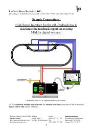
Littfinski DatenTechnik<br />
Be a <strong>Digital</strong>-Professional!<br />
External Switchboard Panel for layouts with PC-Model<br />
Railway Software and Control Unit<br />
Part 1: Key info via s88-feedback bus and switchboard panel illumination<br />
via DCC or Märklin-Motorola<br />
The exemplary conversion of a tracking-control within a model railway<br />
switch tower for the control of the own model railway is a request of<br />
many model railway users. By using a switch board panel is it possible<br />
to control the components of a model railway layout fast, very simple<br />
and not at least exemplary and clear.<br />
<strong>LDT</strong> <strong>Digital</strong>-<strong>Compendium</strong> (<strong>CU</strong>-<strong>GBS</strong>-<strong>DEC</strong>-<strong>001</strong>_<strong>11</strong>_<strong>engl</strong>)<br />
If your model railway layout will be controlled by a PC with a model railway<br />
software (e.g. Railware, TrainController or Win-Digipet) there will<br />
be the track layout of your model layout available at the PC-screen. Unfortunately<br />
will be the control of turnouts or driveways uncomfortable<br />
controlled by mouse clicks.<br />
An external switchboard panel for a part or the total layout controlled by<br />
the model railway software will be a comfortable solution. It makes no<br />
difference if you construct an own switchboard panel or you combine<br />
components of available switchboard panel systems.<br />
But how is the transfer of the key information from the switchboard to<br />
the PC possible and how will work the switchboard illumination for the<br />
turnout-position and track occupancy information<br />
GENERAL<br />
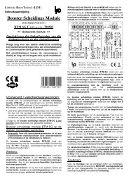
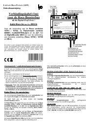
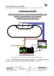
The sample connection at the next page will show you the general setup.<br />
The first requirement (turnout- or signal key information of the switch<br />
board panel to the PC respectively to the model railway software) can<br />
be easily realized via the s88-feedback bus. At the switchboard panel<br />
has to be the standard feedback modules “RM-88-N” installed. Onto<br />
each module can be up to 16 push buttons for 8 turnouts of the<br />
switchboard panel connected.<br />
The second requirement (illumination of turnout- or signal position and<br />
track occupancy information) will be covered by the decoder for<br />
switchboard lights “<strong>GBS</strong>-<strong>DEC</strong>”.
Littfinski DatenTechnik (<strong>LDT</strong>)<br />
Rückmeldemodul RM-88-N<br />
16 - channel feedback module<br />
Rev. 1.0<br />
8<br />
7<br />
6<br />
5<br />
4<br />
3<br />
2<br />
1<br />
32<br />
31<br />
30<br />
29<br />
28<br />
27<br />
26<br />
25<br />
white weiss<br />
24<br />
23<br />
22<br />
21<br />
20<br />
19<br />
18<br />
17<br />
33<br />
34<br />
35<br />
36<br />
37<br />
38<br />
39<br />
40<br />
16<br />
15<br />
14<br />
13<br />
12<br />
<strong>11</strong><br />
10<br />
9<br />
8<br />
7<br />
6<br />
5<br />
4<br />
3<br />
2<br />
1<br />
KL4 KL3 KL2 KL1<br />
KL5<br />
white weiss<br />
Littfinski DatenTechnik (<strong>LDT</strong>)<br />
D-25492 Heist/Germany • Kleiner Ring 9 • www.ldt-infocenter.com<br />
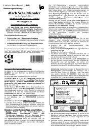
There are three different variances of decoder for switchboard lights<br />
available:<br />
• the “<strong>GBS</strong>-<strong>DEC</strong>-DC” will switch the illumination of the controlpanel<br />
by using the DCC-data format,<br />
• the “<strong>GBS</strong>-<strong>DEC</strong>-MM” will switch the illumination of the control<br />
panel by using the Märklin-Motorola-data format and<br />
• the “<strong>GBS</strong>-<strong>DEC</strong>-s88” will respond to the s88-feedback bus and<br />
will directly illuminate the track occupancy reports or the turnout<br />
positions information received from a turnout feedback. This<br />
possibility will be described in detail within the second part of this<br />
compendium article under “Switch panel illumination directly via<br />
the s88-feedback reports”.<br />
Adr: 16 . . . 1<br />
J<br />
braun<br />
brown<br />
K<br />
rot<br />
red<br />
J K<br />
br. rt IN<br />
s88<br />
s88<br />
OUT<br />
10<br />
9<br />
KL6<br />
<strong>11</strong><br />
16<br />
15<br />
14<br />
13<br />
12<br />
KL5<br />
KL4<br />
KL3<br />
KL2<br />
<strong>Digital</strong>-Profi werden!<br />
Rückmeldemodul<br />
RM-88-N<br />
16 Rückmeldeeingänge für den<br />
s88-Rückmeldebus.<br />
Littfinski DatenTechnik<br />
s88-N<br />
D-25492 Heist<br />
www.ldt-infocenter.com<br />
KL1<br />
Littfinski DatenTechnik (<strong>LDT</strong>)<br />
BU1<br />
ST1 BU1<br />
KL1<br />
ST2<br />
ST1<br />
BU2<br />
BU1<br />
s88-N<br />
OUT<br />
OUT<br />
ST1<br />
weiss<br />
white<br />
ST2<br />
Bestellbezeichnung<br />
/<br />
Order code:<br />
Kabel s88 xm<br />
IN<br />
s88-N<br />
IN<br />
BU2<br />
KL7<br />
<strong>GBS</strong>-Display<br />
Light-Display<br />
Rev. 1.5<br />
<strong>GBS</strong>-Display<br />
KL6<br />
braun gelb<br />
10..18V~<br />
<strong>GBS</strong>-Master<br />
Rev. 1.2<br />
Littfinski DatenTechnik (<strong>LDT</strong>)<br />
<strong>GBS</strong>-Master<br />
Vom Modellbahntrafo<br />
From transformer<br />
braun<br />
brown<br />
gelb<br />
yellow<br />
•<br />
external switch<br />
board panel with<br />
PC-control (page_788)<br />
08<br />
märklin<br />
digital<br />
1<strong>001</strong>50<br />
50<br />
200<br />
0<br />
250<br />
märklin<br />
digital<br />
Computer<br />
RS232<br />
S-Bahn<br />
Erzwagenzug<br />
ET 85<br />
control unit<br />
interface<br />
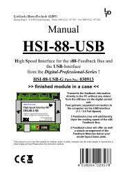
CONNECTING TURNOUT PUSHBUTTONS OF THE SWITCH PANEL<br />
Each feedback module “RM-88-N“ contains 16 inputs for the connection<br />
of 16 push buttons for 8 turnout symbols.<br />
The common wire of all push buttons will be connected to the ground<br />
clamp (center clamp of the 17 poles clamp bar of the “RM-88-N”) (black<br />
wire to the “RM-88-N” shown at the sample connection).<br />
At the control panel will be normally a push button for “turnout round“<br />
and a push button for “turnout straight” for each turnout symbol available.<br />
Instead of push buttons can be switches used whenever the<br />
switch panel controlling model railway software is able to support this.<br />
The second connection of each push button will be connected to one of<br />
the inputs 1 to 16 of the feedback module (blue wires to the “RM-88-N“).<br />
If the control panel contains more than 8 turnouts is it required to connect<br />
several feedback modules “RM-88-N” in serie.<br />
Page 2 / 16<br />
<strong>LDT</strong> <strong>Digital</strong>-<strong>Compendium</strong> <strong>CU</strong>-<strong>GBS</strong>-<strong>DEC</strong>-<strong>001</strong>_<strong>11</strong>_<strong>engl</strong>
Littfinski DatenTechnik (<strong>LDT</strong>)<br />
Rev. 1.0<br />
OUT<br />
IN<br />
Littfinski DatenTechnik (<strong>LDT</strong>)<br />
Rev. 1.0<br />
OUT<br />
IN<br />
8<br />
7<br />
6<br />
5<br />
4<br />
3<br />
2<br />
1<br />
8<br />
7<br />
6<br />
5<br />
4<br />
3<br />
2<br />
1<br />
Left<br />
ST2<br />
ST1<br />
OUT<br />
9ABCDEF 01234 56 78<br />
A = 10<br />
B = <strong>11</strong><br />
C = 12<br />
D = 13<br />
E = 14<br />
F = 15<br />
Right<br />
Dataswitch for the s88 feedback bus<br />
Datenweiche für den s88 Rückmeldebus<br />
Rev. 2.0<br />
Littfinski DatenTechnik<br />
ST3<br />
Littfinski DatenTechnik (<strong>LDT</strong>)<br />
Rückmeldemodul RM-88-N<br />
16 - channel feedback module<br />
Rev. 1.0<br />
OUT<br />
IN<br />
Littfinski DatenTechnik (<strong>LDT</strong>)<br />
Rev. 1.0<br />
OUT<br />
IN<br />
8<br />
7<br />
6<br />
5<br />
4<br />
3<br />
2<br />
1<br />
8<br />
7<br />
6<br />
5<br />
4<br />
3<br />
2<br />
1<br />
Littfinski DatenTechnik (<strong>LDT</strong>)<br />
D-25492 Heist/Germany • Kleiner Ring 9 • www.ldt-infocenter.com<br />
Taster "Weiche rund"<br />
Key "turnout round"<br />
Taster "Weiche gerade"<br />
Key "turnout straight"<br />
8<br />
7<br />
6<br />
5<br />
4<br />
3<br />
2<br />
1<br />
16<br />
15<br />
14<br />
13<br />
12<br />
<strong>11</strong><br />
10<br />
9<br />
KL1<br />
KL2<br />
KL3<br />
KL4<br />
KL5<br />
KL6<br />
BU1<br />
<strong>Digital</strong>-Profi werden!<br />
Rückmeldemodul<br />
RM-88-N<br />
16 Rückmeldeeingänge für den<br />
s88-Rückmeldebus.<br />
s88-N<br />
OUT<br />
s88-N<br />
Littfinski DatenTechnik (<strong>LDT</strong>)<br />
Rückmeldemodul RM-88-N<br />
16 - channel feedback module<br />
ST1 ST2 Rev. 1.0<br />
OUT<br />
weiss<br />
white<br />
Bestellbezeichnung<br />
/<br />
Order code:<br />
Kabel s88 xm<br />
S88- Rückmeldebus<br />
S88- feedback bus<br />
Littfinski DatenTechnik<br />
D-25492 Heist<br />
www.ldt-infocenter.com<br />
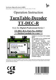
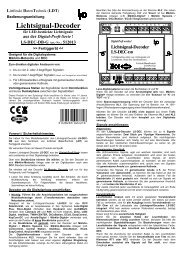
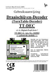
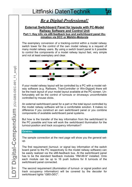
Because the control panel will be normally installed near the digital central<br />
unit is a simple distribution of the s88-feedbackbus via the data<br />
switch “DSW-88“ possible. In this case is a re-numbering of the already<br />
assembled feedback modules not required.<br />
10<br />
9<br />
<strong>11</strong><br />
16<br />
15<br />
14<br />
13<br />
12<br />
Ref<br />
IN<br />
s88-N<br />
IN<br />
BU2<br />
Taster "Weiche rund"<br />
Key "turnout round"<br />
Taster "Weiche gerade"<br />
Key "turnout straight"<br />
•<br />
the key information<br />
from turnout<br />
or signal keys will<br />
be received by the<br />
PC via the feedback<br />
modules.<br />
10<br />
9<br />
KL6<br />
BU1<br />
<strong>11</strong><br />
16<br />
15<br />
14<br />
13<br />
12<br />
KL5<br />
KL4<br />
KL3<br />
KL2<br />
<strong>Digital</strong>-Profi werden!<br />
Rückmeldemodul<br />
RM-88-N<br />
16 Rückmeldeeingänge für den<br />
s88-Rückmeldebus.<br />
Littfinski DatenTechnik<br />
s88-N<br />
D-25492 Heist<br />
www.ldt-infocenter.com<br />
s88-N<br />
OUT<br />
ST1 ST2<br />
s88-N<br />
IN<br />
KL1<br />
BU2<br />
16<br />
15<br />
14<br />
13<br />
12<br />
<strong>11</strong><br />
10<br />
9<br />
Ref<br />
16<br />
15<br />
14<br />
13<br />
12<br />
<strong>11</strong><br />
10<br />
9<br />
KL1<br />
KL2<br />
KL3<br />
KL4<br />
KL5<br />
KL6<br />
KL1<br />
KL2<br />
KL3<br />
KL4<br />
KL5<br />
KL6<br />
KL1<br />
KL2<br />
KL3<br />
KL4<br />
KL5<br />
KL6<br />
X.<br />
<strong>Digital</strong>-Profi werden!<br />
Rückmeldemodul<br />
RM-88-N-Opto<br />
16 galvanisch getrennte Rückmeldeeingänge<br />
für den s88-Rückmeldebus.<br />
Littfinski DatenTechnik<br />
s88-N<br />
D-25492 Heist<br />
www.ldt-infocenter.com<br />
Rückmeldemodul RM-88-N-Opto<br />
16 - channel feedback module<br />
s88-N<br />
ST1 ST2<br />
s88-N<br />
BU1<br />
OUT<br />
OUT<br />
weiss<br />
white<br />
IN<br />
BU2<br />
Bestellbezeichnung<br />
/<br />
Order code:<br />
Kabel s88 xm<br />
X+2<br />
OUT<br />
weiss<br />
white<br />
Bestellbezeichnung<br />
/<br />
Order code:<br />
Kabel s88 xm<br />
<strong>Digital</strong>-Profi werden!<br />
Rückmeldemodul<br />
RM-88-N-Opto<br />
1 X+1<br />
16 galvanisch getrennte Rückmeldeeingänge<br />
für den s88-Rückmeldebus.<br />
Littfinski DatenTechnik<br />
s88-N<br />
D-25492 Heist<br />
www.ldt-infocenter.com<br />
<strong>Digital</strong>-Profi werden!<br />
Rückmeldemodul<br />
RM-88-N<br />
16 Rückmeldeeingänge für den<br />
s88-Rückmeldebus.<br />
Littfinski DatenTechnik<br />
s88-N<br />
D-25492 Heist<br />
www.ldt-infocenter.com<br />
Rückmeldemodul RM-88-N-Opto<br />
16 - channel feedback module<br />
Rückmeldemodul RM-88-N<br />
16 - channel feedback module<br />
BU1<br />
s88-N<br />
OUT<br />
OUT<br />
ST1 ST2<br />
weiss<br />
white<br />
s88-N<br />
IN<br />
IN<br />
BU2<br />
Bestellbezeichnung<br />
/<br />
Order code:<br />
Kabel s88 xm<br />
X<br />
Bestellbezeichnung<br />
/<br />
Order code:<br />
Kabel s88 xm<br />
BU1<br />
s88-N<br />
OUT<br />
OUT<br />
ST1 ST2<br />
weiss<br />
white<br />
s88-N<br />
IN<br />
IN<br />
BU2<br />
Rückmeldemodule der Anlage<br />
Layout feedback modules<br />
Rückmeldemodule im Gleisbildstellpult<br />
Switchboard feedback modules<br />
<strong>Digital</strong>-Profi werden!<br />
Datenweiche<br />
DSW-88<br />
Datenweiche für den s88-Rückmeldebus.<br />
Littfinski DatenTechnik<br />
D-25492 Heist<br />
www.ldt-infocenter.com<br />
rosa<br />
grau<br />
gelb<br />
gruen<br />
braun<br />
weiss<br />
DSW-88<br />
S-Bahn<br />
•<br />
branching of the<br />
s88-feedback bus<br />
via data switch<br />
“DSW-88”.<br />
(page_804)<br />
Erzwagenzug<br />
08<br />
märklin<br />
digital<br />
märklin<br />
digital<br />
Computer<br />
RS232<br />
ET 85<br />
1<strong>001</strong>50<br />
50<br />
200<br />
0<br />
250<br />
control unit<br />
interface<br />
<strong>LDT</strong> <strong>Digital</strong>-<strong>Compendium</strong> <strong>CU</strong>-<strong>GBS</strong>-<strong>DEC</strong>-<strong>001</strong>_<strong>11</strong>_<strong>engl</strong> Page 3 / 16
Littfinski DatenTechnik (<strong>LDT</strong>)<br />
D-25492 Heist/Germany • Kleiner Ring 9 • www.ldt-infocenter.com<br />
The connection sample shows that the feedback modules 1 to X are the<br />
feedback modules of the layout.<br />
The s88-feedback bus will be branched via the data switch “DSW-88” to<br />
the feedback modules X+1 and X+2. These feedback modules are included<br />
within the switch control panel and will transfer the key information<br />
of the control panel to the model railway software, which controls<br />
the switch panel.<br />
ILLUMINATION OF THE SWITCH CONTROL PANEL<br />
The decoder for switchboard lights “<strong>GBS</strong>-<strong>DEC</strong>” illuminates the control<br />
panel. The decoder consists out of three components:<br />
The <strong>GBS</strong>-Master-Module (right module at the sample connection on<br />
page 2) is the “brain“ of the control and shall be connected to the digital<br />
current circuit or the feedback bus s88 (attend to part 2) of the digital<br />
central unit. It evaluates the digital information of the central unit or from<br />
the feedback bus and transfers them to the display units.<br />
With the <strong>GBS</strong>-Service-Module (attend to the below chapter “Programming<br />
and Address Section“) will be the addresses of the system assigned.<br />
For operation is the connection of the <strong>GBS</strong>-Service Module not<br />
required. The Service-Module can be detached from the <strong>GBS</strong>-Master-<br />
Module until address assignments on further master modules are required.<br />
One <strong>GBS</strong>-Display-Module (left modules at the sample connection on<br />
page 2) can illuminate up to 16 turnout symbols, 32 track occupancy<br />
symbols or various 2- to 4-aspect light-signals at the switchboard control<br />
panel. At a total is it possible to connect up to 4 display modules<br />
onto one master-module. With this 4 modules is it possible to illuminate<br />
64 turnouts or 128 track occupancies.<br />
•<br />
attend to the<br />
current consumption<br />
of the display<br />
elements!<br />
•<br />
LED – Light<br />
Emitting Diode<br />
The <strong>GBS</strong>-Display-Module is identical to the Light-Display of the<br />
Light@Night system for the light control.<br />
Every single display output is able to supply a current of up to 0.5 Ampere<br />
(A). The total current of one display module shall not exceed 3<br />
Ampere.<br />
Not only light emitting diodes (LED) with serial resistor can be used at<br />
the switchboard but incandescent lamps as well.<br />
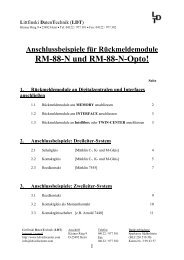
THE CONNECTION OF MODULES<br />
The decoder for switchboard lights “<strong>GBS</strong>-<strong>DEC</strong>“ respectively the <strong>GBS</strong>-<br />
Master-Module shall be connected to the digital current circuit as any<br />
other decoder. The decoder receives therefore the switch information<br />
for the illumination of turnouts or signals from the central digital unit or<br />
from the PC.<br />
Page 4 / 16<br />
<strong>LDT</strong> <strong>Digital</strong>-<strong>Compendium</strong> <strong>CU</strong>-<strong>GBS</strong>-<strong>DEC</strong>-<strong>001</strong>_<strong>11</strong>_<strong>engl</strong>
Littfinski DatenTechnik (<strong>LDT</strong>)<br />
D-25492 Heist/Germany • Kleiner Ring 9 • www.ldt-infocenter.com<br />
Von Steuereinheit<br />
oder Booster<br />
From command station<br />
or booster<br />
J<br />
braun<br />
brown<br />
K<br />
rot<br />
red<br />
3<br />
2<br />
1<br />
J<br />
br.<br />
K<br />
rt<br />
IN<br />
s88<br />
s88<br />
OUT<br />
ST2<br />
ST1<br />
KL1<br />
BU2<br />
ST1<br />
BU1<br />
white weiss<br />
gelb<br />
10..18V~<br />
KL6<br />
<strong>GBS</strong>-Master<br />
Rev. 1.2<br />
Littfinski DatenTechnik (<strong>LDT</strong>)<br />
•<br />
the <strong>GBS</strong>-Master-<br />
Module shall be<br />
connected to the<br />
digital ring conductor<br />
(page_183)<br />
The digital current will be supplied at the two poles clamp KL1. The indicated<br />
colors red / brown correspond to the cable colors for the digital<br />
current recommended by us and be used by company Märklin for the<br />
Control Unit.<br />
The turnout decoder (e.g. turnout decoder “S-<strong>DEC</strong>-4”) actually switches<br />
a turnout after receiving a corresponding command from the digital central<br />
unit. At the same time will switch the “<strong>GBS</strong>-<strong>DEC</strong>” the light for the<br />
corresponding turnout at the switchboard.<br />
The “<strong>GBS</strong>-<strong>DEC</strong>” is available for the digital formats of Märklin-Motorola<br />
and DCC: If you switch the turnouts at your layout with the Märklin-<br />
Motorola format you should select the Master Module <strong>GBS</strong>-Master-MM.<br />
If you switch the turnouts with the DCC-format you should select the<br />
<strong>GBS</strong>-Master-DC Module.<br />
<strong>LDT</strong> <strong>Digital</strong>-<strong>Compendium</strong> <strong>CU</strong>-<strong>GBS</strong>-<strong>DEC</strong>-<strong>001</strong>_<strong>11</strong>_<strong>engl</strong> Page 5 / 16
Littfinski DatenTechnik (<strong>LDT</strong>)<br />
D-25492 Heist/Germany • Kleiner Ring 9 • www.ldt-infocenter.com<br />
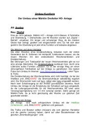
The <strong>GBS</strong>-Display-Modules will be connected to the left side of the Master-Module.<br />
To prevent an excessive digital current consumption for the<br />
illumination of the control panel is it recommended to supply the <strong>GBS</strong>-<br />
Display-Modules from a simple light transformer.<br />
32<br />
31<br />
30<br />
29<br />
28<br />
27<br />
26<br />
25<br />
24<br />
23<br />
22<br />
21<br />
20<br />
19<br />
18<br />
17<br />
16<br />
15<br />
14<br />
13<br />
12<br />
<strong>11</strong><br />
10<br />
9<br />
8<br />
7<br />
6<br />
5<br />
4<br />
3<br />
2<br />
1<br />
J<br />
br.<br />
Littfinski DatenTechnik (<strong>LDT</strong>)<br />
KL4 KL3 KL2 KL1<br />
BU1<br />
ST1<br />
BU1<br />
white weiss<br />
white weiss<br />
•<br />
each <strong>GBS</strong>-<br />
Display-Module<br />
receives the<br />
supply from a light<br />
transformer<br />
(page_183)<br />
KL7<br />
KL5<br />
33<br />
34<br />
35<br />
36<br />
37<br />
38<br />
39<br />
40<br />
<strong>GBS</strong>-Display<br />
Light-Display<br />
Rev. 1.5<br />
braun gelb<br />
10..18V~<br />
KL6<br />
braun<br />
brown<br />
gelb<br />
yellow<br />
Vom Modellbahntrafo<br />
From transformer<br />
The external AC voltage supply of 14..18 V ~ (e.g. light output of a<br />
model railway transformer) will be connected to the two-poles clamp<br />
KL6.<br />
Page 6 / 16<br />
<strong>LDT</strong> <strong>Digital</strong>-<strong>Compendium</strong> <strong>CU</strong>-<strong>GBS</strong>-<strong>DEC</strong>-<strong>001</strong>_<strong>11</strong>_<strong>engl</strong>
Littfinski DatenTechnik (<strong>LDT</strong>)<br />
D-25492 Heist/Germany • Kleiner Ring 9 • www.ldt-infocenter.com<br />
CONNECTING SWITCH BOARD SYMBOLS<br />
Proceed with any electrical connections only after switching-off the layout<br />
(switch-off the transformers or disconnect the main plug)!<br />
The maximum current load will be 0,5 Ampere on each output. The<br />
common connection of all lamps or light emitting diodes is the three<br />
poles clamp KL7. Each positive connection of the clamp KL7 can cover<br />
a load of 1 Ampere and therefore a total load of a complete Display-<br />
Module can be up to 3 Ampere.<br />
max. 0,5 Ampere<br />
32<br />
31<br />
30<br />
29<br />
28<br />
27<br />
26<br />
25<br />
24<br />
23<br />
22<br />
21<br />
20<br />
19<br />
18<br />
17<br />
16<br />
15<br />
14<br />
13<br />
12<br />
<strong>11</strong><br />
10<br />
9<br />
8<br />
7<br />
6<br />
5<br />
4<br />
3<br />
2<br />
1<br />
J<br />
br.<br />
Littfinski DatenTechnik (<strong>LDT</strong>)<br />
KL4 KL3 KL2 KL1<br />
BU1<br />
ST1<br />
BU1<br />
white weiss<br />
white weiss<br />
KL5<br />
KL7<br />
max. 1 Ampere<br />
33<br />
34<br />
35<br />
36<br />
37<br />
38<br />
39<br />
40<br />
<strong>GBS</strong>-Display<br />
Light-Display<br />
Rev. 1.5<br />
braun<br />
brown<br />
braun gelb<br />
10..18V~<br />
KL6<br />
gelb<br />
yellow<br />
Vom Modellbahntrafo<br />
From transformer<br />
•<br />
maximum current<br />
load<br />
(page_214)<br />
<strong>LDT</strong> <strong>Digital</strong>-<strong>Compendium</strong> <strong>CU</strong>-<strong>GBS</strong>-<strong>DEC</strong>-<strong>001</strong>_<strong>11</strong>_<strong>engl</strong> Page 7 / 16
Littfinski DatenTechnik (<strong>LDT</strong>)<br />
D-25492 Heist/Germany • Kleiner Ring 9 • www.ldt-infocenter.com<br />
Apart from incandescent lamps for model railways is it possible to connect<br />
light emitting diodes (LED) for the indication of occupancy reports,<br />
turnout positions or signal aspects at the Display-Module.<br />
By using LED lamps is a serial resistor absolutely required (normally 4,7<br />
to 10 kOhm. The common positive connection for all outputs is the<br />
clamp KL7. On LED lamps will be the plus pole (anode) marked by one<br />
longer connection wire.<br />
It is as well possible to use two-colored LEDs with three connections<br />
and one common anode.<br />
Modellbahnlämpchen<br />
model incandescent<br />
lamp<br />
Leuchtdiode<br />
light-emitting diode<br />
Vorwiderstand<br />
series resistor<br />
32<br />
31<br />
30<br />
29<br />
28<br />
27<br />
26<br />
25<br />
24<br />
23<br />
22<br />
21<br />
20<br />
19<br />
18<br />
17<br />
16<br />
15<br />
14<br />
13<br />
12<br />
<strong>11</strong><br />
10<br />
9<br />
8<br />
7<br />
6<br />
5<br />
4<br />
3<br />
2<br />
1<br />
Littfinski DatenTechnik (<strong>LDT</strong>)<br />
KL4 KL3 KL2 KL1<br />
BU1<br />
ST1<br />
white weiss<br />
white weiss<br />
KL5<br />
•<br />
connecting incandescent<br />
model<br />
railway lamps<br />
and LED`s<br />
(page_181)<br />
KL7<br />
33<br />
34<br />
35<br />
36<br />
37<br />
38<br />
39<br />
40<br />
<strong>GBS</strong>-Display<br />
Light-Display<br />
Rev. 1.5<br />
braun<br />
brown<br />
braun gelb<br />
10..18V~<br />
KL6<br />
gelb<br />
yellow<br />
Vom Modellbahntrafo<br />
From transformer<br />
Not only turnout symbols but also track symbols for occupancy reports<br />
can be connected to the Display-Modules.<br />
On this way is it possible to illuminate driveways via turnout addresses.<br />
For this issue will be turnout addresses used which will not be used for<br />
switching turnouts within the layout.<br />
Page 8 / 16<br />
<strong>LDT</strong> <strong>Digital</strong>-<strong>Compendium</strong> <strong>CU</strong>-<strong>GBS</strong>-<strong>DEC</strong>-<strong>001</strong>_<strong>11</strong>_<strong>engl</strong>
Littfinski DatenTechnik (<strong>LDT</strong>)<br />
D-25492 Heist/Germany • Kleiner Ring 9 • www.ldt-infocenter.com<br />
Contrary to the above is it possible to use the “<strong>GBS</strong>-<strong>DEC</strong>-s88” for track<br />
occupancy reports or turnout positions received from turnout feedback<br />
reports. This possibility will be described within part 2 of this compendium<br />
under “switch panel illumination directly via s88-feedback reports”.<br />
1<br />
32<br />
31<br />
30<br />
29<br />
28<br />
27<br />
26<br />
25<br />
24<br />
23<br />
22<br />
21<br />
20<br />
19<br />
18<br />
17<br />
16<br />
15<br />
14<br />
13<br />
12<br />
<strong>11</strong><br />
10<br />
9<br />
8<br />
7<br />
6<br />
5<br />
4<br />
3<br />
2<br />
1<br />
Littfinski DatenTechnik (<strong>LDT</strong>)<br />
KL4 KL3 KL2 KL1<br />
BU1<br />
ST1<br />
white weiss<br />
white weiss<br />
KL7<br />
KL5<br />
33<br />
34<br />
35<br />
36<br />
37<br />
38<br />
39<br />
40<br />
<strong>GBS</strong>-Display<br />
Light-Display<br />
Rev. 1.5<br />
braun gelb<br />
10..18V~<br />
KL6<br />
•<br />
connecting<br />
track- and<br />
turnout symbols<br />
braun<br />
brown<br />
gelb<br />
yellow<br />
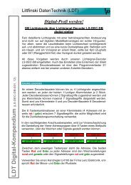
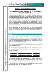
ADDRESS- AND FUNCTION ADJUSTMENTS<br />
Each of the four Display-Modules to be connected to one Master-<br />
Module receives 16 coherent addresses (=group of addresses). For<br />
each address of 1-256 will be two outputs assigned i.e. G (for turnout<br />
straight) and R (for turnout round).<br />
<strong>LDT</strong> <strong>Digital</strong>-<strong>Compendium</strong> <strong>CU</strong>-<strong>GBS</strong>-<strong>DEC</strong>-<strong>001</strong>_<strong>11</strong>_<strong>engl</strong> Page 9 / 16
Littfinski DatenTechnik (<strong>LDT</strong>)<br />
D-25492 Heist/Germany • Kleiner Ring 9 • www.ldt-infocenter.com<br />
•<br />
possible address<br />
ranges of the<br />
<strong>GBS</strong>-Display-<br />
Modules<br />
(page_182)<br />
Dis1 Adr:256-241<br />
Dis1 Adr:240-225<br />
Dis1 Adr:224-209<br />
Dis1 Adr:208-193<br />
Dis1 Adr:192-177<br />
Dis1 Adr:176-161<br />
Dis1 Adr:160-145<br />
Dis1 Adr:144-129<br />
Dis1 Adr:128-<strong>11</strong>3<br />
Dis1 Adr:<strong>11</strong>2-097<br />
Dis1 Adr:096-081<br />
Dis1 Adr:080-065<br />
Dis1 Adr:064-049<br />
Dis1 Adr:048-033<br />
Dis1 Adr:032-017<br />
Dis1 Adr:016-<strong>001</strong><br />
Littfinski DatenTechnik (<strong>LDT</strong>)<br />
256 255 254 253<br />
240 239 238 237<br />
224 223 222 221<br />
208 207 206 205<br />
192 191 190 189<br />
176 175 174 173<br />
160 159 158 157<br />
144 143 142 141<br />
128 127 126 125<br />
<strong>11</strong>2 <strong>11</strong>1 <strong>11</strong>0 109<br />
96 95 94 93<br />
80 79 78 77<br />
64 63 62 61<br />
48 47 46 45<br />
32 31 30 29<br />
16 15 14 13<br />
G R G R G R G R<br />
32<br />
31<br />
30<br />
29<br />
28<br />
27<br />
26<br />
25<br />
252<br />
236<br />
220<br />
204<br />
188<br />
172<br />
156<br />
140<br />
124<br />
108<br />
92<br />
76<br />
60<br />
44<br />
28<br />
12<br />
251<br />
235<br />
219<br />
203<br />
187<br />
171<br />
155<br />
139<br />
123<br />
107<br />
91<br />
75<br />
59<br />
43<br />
27<br />
<strong>11</strong><br />
250<br />
234<br />
218<br />
202<br />
186<br />
170<br />
154<br />
138<br />
122<br />
106<br />
90<br />
74<br />
58<br />
42<br />
26<br />
10<br />
249<br />
233<br />
217<br />
201<br />
185<br />
169<br />
153<br />
137<br />
121<br />
105<br />
89<br />
73<br />
57<br />
41<br />
25<br />
9<br />
G R G R G R G R<br />
24<br />
23<br />
22<br />
21<br />
20<br />
19<br />
18<br />
17<br />
248<br />
232<br />
216<br />
200<br />
184<br />
168<br />
152<br />
136<br />
120<br />
104<br />
88<br />
72<br />
56<br />
40<br />
24<br />
8<br />
247<br />
231<br />
215<br />
199<br />
183<br />
167<br />
151<br />
135<br />
<strong>11</strong>9<br />
103<br />
87<br />
71<br />
55<br />
39<br />
23<br />
7<br />
246<br />
230<br />
214<br />
198<br />
182<br />
166<br />
150<br />
134<br />
<strong>11</strong>8<br />
102<br />
86<br />
70<br />
54<br />
38<br />
22<br />
6<br />
245<br />
229<br />
213<br />
197<br />
181<br />
165<br />
149<br />
133<br />
<strong>11</strong>7<br />
101<br />
85<br />
69<br />
53<br />
37<br />
21<br />
5<br />
G R G R G R G R<br />
16<br />
15<br />
14<br />
13<br />
12<br />
<strong>11</strong><br />
10<br />
9<br />
244<br />
228<br />
212<br />
196<br />
180<br />
164<br />
148<br />
132<br />
<strong>11</strong>6<br />
100<br />
84<br />
68<br />
52<br />
36<br />
20<br />
4<br />
243<br />
227<br />
2<strong>11</strong><br />
195<br />
179<br />
163<br />
147<br />
131<br />
<strong>11</strong>5<br />
99<br />
83<br />
67<br />
51<br />
35<br />
19<br />
3<br />
242<br />
226<br />
210<br />
194<br />
178<br />
162<br />
146<br />
130<br />
<strong>11</strong>4<br />
98<br />
82<br />
66<br />
50<br />
34<br />
18<br />
2<br />
241<br />
225<br />
209<br />
193<br />
177<br />
161<br />
145<br />
129<br />
<strong>11</strong>3<br />
97<br />
81<br />
65<br />
49<br />
33<br />
17<br />
1<br />
G R G R G R G R<br />
KL4 KL3 KL2 KL1<br />
At the <strong>GBS</strong>-Service-Module connected to the right side of the Master-<br />
Module for the programming process (please attend as well to the below<br />
section “Programming and Address Ranges”) is it possible to set<br />
the quantity of Display-Modules (maximum 4), which shall be controlled<br />
by the Master-Module, respectively how many Display-Modules are<br />
connected.<br />
8<br />
7<br />
6<br />
5<br />
4<br />
3<br />
2<br />
1<br />
Now you can enter the address range and the function of the outputs<br />
for each Display-Module:<br />
Dis1<br />
Dis1<br />
Dis1<br />
Dis1<br />
Dis1<br />
Adr:016–<strong>001</strong><br />
K08-01:****<br />
K16-09:****<br />
K24-17:****<br />
K32-25:****<br />
The above table indicates that the first Display-Module (Dis1) left from<br />
the <strong>GBS</strong>-Master-Module will use the address range 1 to 16. All four<br />
block clamps KL1 to KL4 with the addresses K08-01, K16-09, K24-17<br />
and K32-25 will be standard switch outputs.<br />
With the adjustment “****” will be indicated that the outputs at the contacts<br />
1 to 32 will be switched as pairs.<br />
This follows that turnout symbols or block signals which are connected<br />
at the clamps 1/2, 3/4, 5/6, etc. can be switched from round to straight<br />
respectively red to green by using the addresses 1 to 16.<br />
Page 10 / 16<br />
<strong>LDT</strong> <strong>Digital</strong>-<strong>Compendium</strong> <strong>CU</strong>-<strong>GBS</strong>-<strong>DEC</strong>-<strong>001</strong>_<strong>11</strong>_<strong>engl</strong>
Littfinski DatenTechnik (<strong>LDT</strong>)<br />
D-25492 Heist/Germany • Kleiner Ring 9 • www.ldt-infocenter.com<br />
CONNECTING LIGHT SIGNALS<br />
Light signals used at the layout and on the switch panel can be controlled<br />
by the “<strong>GBS</strong>-<strong>DEC</strong>” as well. The placing of addresses at the<br />
“<strong>GBS</strong>-<strong>DEC</strong>” works on the same way on the layout as on the Light Signal-Decoder<br />
LS-<strong>DEC</strong>-DB.<br />
In this case will be each of the two clamp bars of the LS-<strong>DEC</strong>-DB comply<br />
with one of 16 the four clamp 12 blocks of the 2Display-Module.<br />
1<br />
RT1<br />
GN<br />
RT1<br />
RT1<br />
GN<br />
RT1<br />
GE<br />
GE<br />
RT1<br />
GN<br />
RT1<br />
GN<br />
32<br />
31<br />
30<br />
29<br />
28<br />
27<br />
26<br />
25<br />
24<br />
23<br />
22<br />
21<br />
20<br />
19<br />
18<br />
17<br />
16<br />
15<br />
14<br />
13<br />
12<br />
<strong>11</strong><br />
10<br />
9<br />
8<br />
7<br />
6<br />
5<br />
4<br />
3<br />
2<br />
1<br />
Littfinski DatenTechnik (<strong>LDT</strong>)<br />
KL4 KL3 KL2 KL1<br />
BU1<br />
ST1<br />
BU1<br />
white weiss<br />
KL7<br />
KL5<br />
33<br />
34<br />
35<br />
36<br />
37<br />
38<br />
39<br />
40<br />
<strong>GBS</strong>-Display<br />
Light-Display<br />
Rev. 1.5<br />
braun<br />
brown<br />
braun gelb<br />
10..18V~<br />
white weiss<br />
KL6<br />
gelb<br />
yellow<br />
Each block- and line-close-signal needs one digital address for the indication<br />
of the signal aspects Hp0, Hp1, Sh0 and Sh1. The light emitting<br />
diodes or incandescent lamps of signals will be connected at the<br />
clamps KL1 to KL4 for example to the contacts 1–8, 9–16, 17–24 and<br />
25–32.<br />
With the <strong>GBS</strong>-Service-Module is it possible to enter the following adjustments<br />
for the control of block- and line-close-signals:<br />
•<br />
control of DB<br />
Block- and Line-<br />
Close-Signal<br />
symbols<br />
(page_185)<br />
Dis1<br />
Dis1<br />
Adr:016–<strong>001</strong><br />
K08-01:****<br />
The above table indicates that the first Display-Module left from the<br />
<strong>GBS</strong>-Master-Module will use the address range 1 to 16 and the outputs<br />
of the clamp bars (at the table exemplary shown for the clamp bar KL1<br />
(K08-01) ) have been set to switch at pairs (red and green) “****“ at the<br />
contacts 1/2, 3/4, 5/6 etc.<br />
<strong>LDT</strong> <strong>Digital</strong>-<strong>Compendium</strong> <strong>CU</strong>-<strong>GBS</strong>-<strong>DEC</strong>-<strong>001</strong>_<strong>11</strong>_<strong>engl</strong> Page <strong>11</strong> / 16
Littfinski DatenTechnik (<strong>LDT</strong>)<br />
D-25492 Heist/Germany • Kleiner Ring 9 • www.ldt-infocenter.com<br />
The next sample shows the connection of one block- and one advancesignal<br />
and indicates the correct settings for the digital control.<br />
The block signal requires again one digital address for the indication of<br />
the signal aspects Hp0 and Hp1. The advance signal requires for all<br />
aspects Vr0, Vr1 und Vr2 two digital addresses.<br />
GE1<br />
GN1<br />
RT1<br />
GN<br />
GE2<br />
GN2<br />
32<br />
31<br />
30<br />
29<br />
28<br />
27<br />
26<br />
25<br />
24<br />
23<br />
22<br />
21<br />
20<br />
19<br />
18<br />
17<br />
16<br />
15<br />
14<br />
13<br />
12<br />
<strong>11</strong><br />
10<br />
9<br />
8<br />
7<br />
6<br />
5<br />
4<br />
3<br />
2<br />
1<br />
GN2<br />
GE2<br />
GN1<br />
GE1<br />
GN<br />
RT1<br />
Littfinski DatenTechnik (<strong>LDT</strong>)<br />
KL4 KL3 KL2 KL1<br />
•<br />
control of DB<br />
Block- and Advance-Signal<br />
Symbols<br />
(page_186)<br />
BU1<br />
white weiss<br />
white weiss<br />
ST1<br />
The block- and advance-signal will occupy one clamp bar for 4 digital<br />
addresses. At the sample will it be the clamp KL1 with the contacts 08<br />
to 01. The following adjustments shall be entered via the service module:<br />
Dis1<br />
Dis1<br />
Adr:016–<strong>001</strong><br />
K08-01:Vo**<br />
The above table will indicate that the first Display-Module at the left side<br />
off the <strong>GBS</strong>-Master-Module uses the addresses 1 to 16.<br />
“Vo**“ indicates that on the clamp KL1 has been one advance signal<br />
connected at the contacts 5-8. The block signal shall be connected to<br />
the contacts 1/2 as described above.<br />
Page 12 / 16<br />
<strong>LDT</strong> <strong>Digital</strong>-<strong>Compendium</strong> <strong>CU</strong>-<strong>GBS</strong>-<strong>DEC</strong>-<strong>001</strong>_<strong>11</strong>_<strong>engl</strong>
Littfinski DatenTechnik (<strong>LDT</strong>)<br />
D-25492 Heist/Germany • Kleiner Ring 9 • www.ldt-infocenter.com<br />
For each Station Entry- and Advance-Signal are two digital addresses<br />
required for the indication of the signal aspects Hp0, Hp1, Hp2, and<br />
Vr0, Vr1 and Vr2.<br />
GN<br />
GE1<br />
GN1<br />
RT1<br />
GE<br />
GE2<br />
GN2<br />
32<br />
31<br />
30<br />
29<br />
28<br />
27<br />
26<br />
25<br />
24<br />
23<br />
22<br />
21<br />
20<br />
19<br />
18<br />
17<br />
16<br />
15<br />
14<br />
13<br />
12<br />
<strong>11</strong><br />
10<br />
9<br />
8<br />
7<br />
6<br />
5<br />
4<br />
3<br />
2<br />
1<br />
GN2<br />
GE2<br />
GN1<br />
GE1<br />
GE<br />
GN<br />
RT1<br />
Littfinski DatenTechnik (<strong>LDT</strong>)<br />
KL4 KL3 KL2 KL1<br />
BU1<br />
ST1<br />
white weiss<br />
white weiss<br />
KL5<br />
KL7<br />
33<br />
34<br />
35<br />
36<br />
37<br />
38<br />
39<br />
40<br />
<strong>GBS</strong>-Display<br />
Light-Display<br />
Rev. 1.5<br />
braun<br />
brown<br />
braun gelb<br />
10..18V~<br />
KL6<br />
gelb<br />
yellow<br />
•<br />
control DB station<br />
entry- and advance<br />
signal<br />
symboles<br />
(page_187)<br />
With the <strong>GBS</strong>-Service-Module is it possible to enter the following adjustments<br />
for the control of one station entry- and one advance-signal<br />
which are for example connected to the clamp bar KL1:<br />
Dis1<br />
Dis1<br />
Adr:016–<strong>001</strong><br />
K08-01:VoHE<br />
This table shows that the first Display-Module on the left side of the<br />
<strong>GBS</strong>-Master-Module uses the address range 1 to 16.<br />
The adjustment at the first clamp KL1 with “VoHE“ indicates that at the<br />
contacts 5-8 is an advance-signal connected and at the contacts 1,2<br />
and 4 a station entry-signal with red, green, and yellow.<br />
<strong>LDT</strong> <strong>Digital</strong>-<strong>Compendium</strong> <strong>CU</strong>-<strong>GBS</strong>-<strong>DEC</strong>-<strong>001</strong>_<strong>11</strong>_<strong>engl</strong> Page 13 / 16
Littfinski DatenTechnik (<strong>LDT</strong>)<br />
D-25492 Heist/Germany • Kleiner Ring 9 • www.ldt-infocenter.com<br />
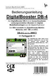
At the next sample will be two digital addresses each used for the control<br />
of one home-signal with the signal aspects Hp0, Hp1, Hp2 and Sh1<br />
and two digital addresses for one advance-signal with the aspects Vr0,<br />
Vr1 and Vr2 connected and established.<br />
GN<br />
RT1<br />
WS<br />
GE<br />
RT2<br />
WS<br />
GE2<br />
GE1<br />
GN2<br />
GN1<br />
32<br />
31<br />
30<br />
29<br />
28<br />
27<br />
26<br />
25<br />
24<br />
23<br />
22<br />
21<br />
20<br />
19<br />
18<br />
17<br />
16<br />
15<br />
14<br />
13<br />
12<br />
<strong>11</strong><br />
10<br />
9<br />
8<br />
7<br />
6<br />
5<br />
4<br />
3<br />
2<br />
1<br />
GN2<br />
GE2<br />
GN1<br />
GE1<br />
GE<br />
RT2<br />
GN<br />
RT1<br />
Littfinski DatenTechnik (<strong>LDT</strong>)<br />
KL4 KL3 KL2 KL1<br />
BU1<br />
ST1<br />
white weiss<br />
white weiss<br />
KL5<br />
•<br />
enlarged connection<br />
drawing at the<br />
sample connection<br />
(page_188)<br />
KL7<br />
33<br />
34<br />
35<br />
36<br />
37<br />
38<br />
39<br />
40<br />
<strong>GBS</strong>-Display<br />
Light-Display<br />
Rev. 1.5<br />
braun gelb<br />
10..18V~<br />
KL6<br />
WS<br />
braun<br />
brown<br />
gelb<br />
yellow<br />
The following settings at the clamp block KL1 for the home- and advance<br />
signal can be adjusted with the <strong>GBS</strong>-Service-Module:<br />
Dis1<br />
Dis1<br />
Adr:016–<strong>001</strong><br />
K08-01:VoHE<br />
The above table indicates that the first Display-Module connected to the<br />
left side of the <strong>GBS</strong>-Master-Module uses the digital addresses1 to 16.<br />
„VoHE“ indicates that at the contacts 5 – 8 is one advance signal connected<br />
and at the contacts 1 – 4 one home signal.<br />
The two white light emitting diodes for the first clamp block K08-01 shall<br />
be connected at the clamp KL5 onto the contact 33.<br />
Page 14 / 16<br />
<strong>LDT</strong> <strong>Digital</strong>-<strong>Compendium</strong> <strong>CU</strong>-<strong>GBS</strong>-<strong>DEC</strong>-<strong>001</strong>_<strong>11</strong>_<strong>engl</strong>
Littfinski DatenTechnik (<strong>LDT</strong>)<br />
D-25492 Heist/Germany • Kleiner Ring 9 • www.ldt-infocenter.com<br />
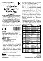
PROGRAMMING AND ADDRESSES<br />
The <strong>GBS</strong>-Service-Module has to be used for the setting of the addresses<br />
according to the tables shown above. The Service-Module has<br />
to be connected to the right side of the Master-Module for this process.<br />
Before connecting the Service-Module to the Master-Module is it absolutely<br />
required to switch-off all model railway transformers, which supply<br />
current to the “<strong>GBS</strong>-<strong>DEC</strong>”.<br />
During the first start will it be eventually required to set a correct contrast<br />
of the LC-Display. For doing this is it necessary to turn carefully<br />
the trimmer R1 (blue component at the drawing) with help of a small<br />
screw driver a half turn to the left or right until the information on the<br />
display is easily readable.<br />
OUT<br />
ST1<br />
R1<br />
BU2<br />
ST1<br />
S3<br />
S2<br />
S1<br />
<strong>GBS</strong>-Service<br />
Rev. 1.0<br />
Littfinski DatenTechnik (<strong>LDT</strong>)<br />
Littfinski DatenTechnik (<strong>LDT</strong>)<br />
S4<br />
<strong>GBS</strong>-Service Modul aufstecken<br />
connect <strong>GBS</strong>-Service Module<br />
•<br />
attend as well to<br />
the drawing at the<br />
sample connection<br />
(page_180)<br />
For the single turnout- and track-occupied symbols will be different address<br />
ranges required. Those have been shown above within the small<br />
tables. The assignment of the address ranges (<strong>001</strong>-016, 017-032, …<br />
241-256) and the functions („****“, „Vo**“, „VoHE“) will be done via the<br />
LC-Display.<br />
For further details please read the operation instruction for the <strong>GBS</strong>-<br />
Master-Module.<br />
<strong>LDT</strong> <strong>Digital</strong>-<strong>Compendium</strong> <strong>CU</strong>-<strong>GBS</strong>-<strong>DEC</strong>-<strong>001</strong>_<strong>11</strong>_<strong>engl</strong> Page 15 / 16
Littfinski DatenTechnik (<strong>LDT</strong>)<br />
D-25492 Heist/Germany • Kleiner Ring 9 • www.ldt-infocenter.com<br />
FURTHER INFORMATION<br />
•<br />
Internet:<br />
http://www.ldtinfocenter.com<br />
Additional information about the operation of digital model railway<br />
components and very helpful sample connections can be found at the<br />
operation instructions which will be supplied together with the<br />
components and modules as well as on our large informative Internet<br />
pages.<br />
All operation instructions can found at the section “Downloads“ of our<br />
Web-Site and all sample connection shown within this article can be<br />
downloaded as PDF-files (e.g. page_788.pdf) and printed at an A4 format.<br />
Authors: Harry Kellner / Peter Littfinski<br />
Subject to technical changes and errors.<br />
© 05/2010 by <strong>LDT</strong><br />
Page 16 / 16<br />
<strong>LDT</strong> <strong>Digital</strong>-<strong>Compendium</strong> <strong>CU</strong>-<strong>GBS</strong>-<strong>DEC</strong>-<strong>001</strong>_<strong>11</strong>_<strong>engl</strong>