Model LIWDDSR20...twin screw loss-in-weight feeder
Model LIWDDSR20...twin screw loss-in-weight feeder Model LIWDDSR20...twin screw loss-in-weight feeder
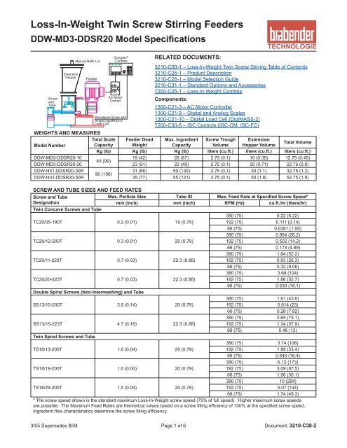
Loss-In-Weight Twin Screw Stirring Feeders DDW-MD3-DDSR20 Model Specifications Screw and Tube Extension Hopper Manual Refill Lid Feeder Congrav ® Controls AC Motor Control Monoblock Scale with Single DigiMASS-2 Load Cell RELATED DOCUMENTS: 3210-C00-1 – Loss-In-Weight Twin Screw Stirring Table of Contents 3210-C25-1 – Product Description 3210-C26-1 – Model Selection Guide 3210-C31-1 – Standard Options and Accessories 7200-C25-1 – Loss-In-Weight Controls Components: 1300-C21-3 – AC Motor Controller 1300-C21-9 – Digital and Analog Scales 1300-C21-10 – Digital Load Cell (DigiMASS-2) 7200-C30-5 – ISC Controls (ISC-CM, ISC-FC) WEIGHTS AND MEASURES Total Scale Feeder Dead Max. Ingredient Screw Trough Extension Total Volume Model Number Capacity Weight Capacity Volume Hopper Volume Kg (lb) Kg (lb) Kg (lb) liters (cu.ft.) liters (cu.ft.) liters (cu.ft.) DDW-MD3-DDSR20-10 19 (42) 26 (57) 2.75 (0.1) 10 (0.35) 12.75 (0.45) 45 (99) DDW-MD3-DDSR20-20 23 (51) 22 (49) 2.75 (0.1) 20 (0.71) 22.75 (0.8) DDW-H31-DDSR20-30R 31 (66) 59 (130) 2.75 (0.1) 30 (1.1) 32.75 (1.2) 90 (198) DDW-H31-DDSR20-50R 35 (77) 55 (121) 2.75 (0.1) 50 (1.8) 52.75 (1.9) SCREW AND TUBE SIZES AND FEED RATES Screw and Tube Designation Max. Particle Size Tube ID Max. Feed Rate at Specified Screw Speed* mm (inch) mm (inch) RPM (Hz) cu.ft./hr (liters/hr) Twin Concave Screws and Tube 380 (75) 0.22 (6.22) TC20/05-190T 0.2 (0.01) 19 (0.75) 192 (75) 0.111 (3.14) 66 (75) 0.0381 (1.08) 380 (75) 0.994 (28.2) TC20/12-200T 0.3 (0.01) 20 (0.79) 192 (75) 0.502 (14.2) 66 (75) 0.173 (4.89) 380 (75) 1.84 (52.2) TC20/11-223T 0.7 (0.03) 22.3 (0.88) 192 (75) 0.93 (26.3) 66 (75) 0.32 (9.06) 380 (75) 3.68 (104) TC20/20-223T 0.7 (0.03) 22.3 (0.88) 192 (75) 1.86 (52.7) 66 (75) 0.639 (18.1) Double Spiral Screws (Non-Intermeshing) and Tube 380 (75) 1.61 (45.6) SS13/10-200T 3.5 (0.14) 20 (0.79) 192 (75) 0.814 (23) 66 (75) 0.28 (7.92) 380 (75) 2.65 (75.1) SS13/15-223T 4.7 (0.18) 22.3 (0.88) 192 (75) 1.34 (37.9) 66 (75) 0.46 (13) Twin Spiral Screws and Tube 380 (75) 3.74 (106) TS18/13-200T 1.0 (0.04) 20 (0.79) 192 (75) 1.89 (53.4) 66 (75) 0.649 (18.4) 380 (75) 6.12 (173) TS18/19-200T 1.0 (0.04) 20 (0.79) 192 (75) 3.09 (87.5) 66 (75) 1.06 (30.1) 380 (75) 10 (284) TS18/29-200T 1.0 (0.04) 20 (0.79) 192 (75) 5.07 (144) 66 (75) 1.74 (49.3) * The screw speed shown is the standard maximum Loss-In-Weight screw speed (75% of full speed). Higher maximum screw speeds are possible. The Maximum Feed Rates are theoretical values based on a screw filling efficiency of 100% at the specified screw speed. Ingredient flow characteristics determine the screw filling efficiency. 3/05 Supersedes 8/04 Page 1 of 6 Document: 3210-C30-2
- Page 2 and 3: DDW-MD3-DDSR20 Model Specifications
- Page 4 and 5: DDW-MD3-DDSR20 Model Specifications
- Page 6: DDW-MD3-DDSR20 Model Specifications
Loss-In-Weight Tw<strong>in</strong> Screw Stirr<strong>in</strong>g Feeders<br />
DDW-MD3-DDSR20 <strong>Model</strong> Specifications<br />
Screw<br />
and<br />
Tube<br />
Extension<br />
Hopper<br />
Manual Refill Lid<br />
Feeder<br />
Congrav ®<br />
Controls<br />
AC Motor<br />
Control<br />
Monoblock Scale with<br />
S<strong>in</strong>gle DigiMASS-2<br />
Load Cell<br />
RELATED DOCUMENTS:<br />
3210-C00-1 – Loss-In-Weight Tw<strong>in</strong> Screw Stirr<strong>in</strong>g Table of Contents<br />
3210-C25-1 – Product Description<br />
3210-C26-1 – <strong>Model</strong> Selection Guide<br />
3210-C31-1 – Standard Options and Accessories<br />
7200-C25-1 – Loss-In-Weight Controls<br />
Components:<br />
1300-C21-3 – AC Motor Controller<br />
1300-C21-9 – Digital and Analog Scales<br />
1300-C21-10 – Digital Load Cell (DigiMASS-2)<br />
7200-C30-5 – ISC Controls (ISC-CM, ISC-FC)<br />
WEIGHTS AND MEASURES<br />
Total Scale Feeder Dead Max. Ingredient Screw Trough Extension<br />
Total Volume<br />
<strong>Model</strong> Number<br />
Capacity Weight<br />
Capacity Volume Hopper Volume<br />
Kg (lb) Kg (lb) Kg (lb) liters (cu.ft.) liters (cu.ft.) liters (cu.ft.)<br />
DDW-MD3-DDSR20-10<br />
19 (42) 26 (57) 2.75 (0.1) 10 (0.35) 12.75 (0.45)<br />
45 (99)<br />
DDW-MD3-DDSR20-20 23 (51) 22 (49) 2.75 (0.1) 20 (0.71) 22.75 (0.8)<br />
DDW-H31-DDSR20-30R<br />
31 (66) 59 (130) 2.75 (0.1) 30 (1.1) 32.75 (1.2)<br />
90 (198)<br />
DDW-H31-DDSR20-50R 35 (77) 55 (121) 2.75 (0.1) 50 (1.8) 52.75 (1.9)<br />
SCREW AND TUBE SIZES AND FEED RATES<br />
Screw and Tube<br />
Designation<br />
Max. Particle Size Tube ID Max. Feed Rate at Specified Screw Speed*<br />
mm (<strong>in</strong>ch) mm (<strong>in</strong>ch) RPM (Hz) cu.ft./hr (liters/hr)<br />
Tw<strong>in</strong> Concave Screws and Tube<br />
380 (75) 0.22 (6.22)<br />
TC20/05-190T 0.2 (0.01) 19 (0.75)<br />
192 (75) 0.111 (3.14)<br />
66 (75) 0.0381 (1.08)<br />
380 (75) 0.994 (28.2)<br />
TC20/12-200T 0.3 (0.01) 20 (0.79)<br />
192 (75) 0.502 (14.2)<br />
66 (75) 0.173 (4.89)<br />
380 (75) 1.84 (52.2)<br />
TC20/11-223T 0.7 (0.03) 22.3 (0.88)<br />
192 (75) 0.93 (26.3)<br />
66 (75) 0.32 (9.06)<br />
380 (75) 3.68 (104)<br />
TC20/20-223T 0.7 (0.03) 22.3 (0.88)<br />
192 (75) 1.86 (52.7)<br />
66 (75) 0.639 (18.1)<br />
Double Spiral Screws (Non-Intermesh<strong>in</strong>g) and Tube<br />
380 (75) 1.61 (45.6)<br />
SS13/10-200T 3.5 (0.14) 20 (0.79)<br />
192 (75) 0.814 (23)<br />
66 (75) 0.28 (7.92)<br />
380 (75) 2.65 (75.1)<br />
SS13/15-223T 4.7 (0.18) 22.3 (0.88)<br />
192 (75) 1.34 (37.9)<br />
66 (75) 0.46 (13)<br />
Tw<strong>in</strong> Spiral Screws and Tube<br />
380 (75) 3.74 (106)<br />
TS18/13-200T 1.0 (0.04) 20 (0.79)<br />
192 (75) 1.89 (53.4)<br />
66 (75) 0.649 (18.4)<br />
380 (75) 6.12 (173)<br />
TS18/19-200T 1.0 (0.04) 20 (0.79)<br />
192 (75) 3.09 (87.5)<br />
66 (75) 1.06 (30.1)<br />
380 (75) 10 (284)<br />
TS18/29-200T 1.0 (0.04) 20 (0.79)<br />
192 (75) 5.07 (144)<br />
66 (75) 1.74 (49.3)<br />
* The <strong>screw</strong> speed shown is the standard maximum Loss-In-Weight <strong>screw</strong> speed (75% of full speed). Higher maximum <strong>screw</strong> speeds<br />
are possible. The Maximum Feed Rates are theoretical values based on a <strong>screw</strong> fill<strong>in</strong>g efficiency of 100% at the specified <strong>screw</strong> speed.<br />
Ingredient flow characteristics determ<strong>in</strong>e the <strong>screw</strong> fill<strong>in</strong>g efficiency.<br />
3/05 Supersedes 8/04 Page 1 of 6 Document: 3210-C30-2
DDW-MD3-DDSR20 <strong>Model</strong> Specifications<br />
MATERIALS OF CONSTRUCTION<br />
Scale<br />
Mild Steel baseplate, enamel pa<strong>in</strong>ted, Alum<strong>in</strong>um, mill f<strong>in</strong>ish and 304SS<br />
Unweighed Process Connection 304SS, electropolished, with polyurethane flexible connection to Vertical Outlet<br />
Screw Trough<br />
304SS, 2B f<strong>in</strong>ish <strong>in</strong>side, mirror f<strong>in</strong>ish outside<br />
Screw, Tube and Agitator 304SS, 2B f<strong>in</strong>ish, electropolished<br />
Screw and Agitator Drive Shafts 304SS<br />
Drive Shaft Seals<br />
Screws and Screw Trough Agitator: Lip Seals <strong>in</strong> gearbox;<br />
Extension Hopper Agitator (-xxR): Viton or BunaN<br />
Extension Hopper and Lid 304SS, 2B f<strong>in</strong>ish <strong>in</strong>side, mirror f<strong>in</strong>ish outside<br />
Gaskets<br />
Neoprene<br />
MECHANICAL PROCESS CONNECTIONS<br />
Refill (on Lid) Pipe stub connection. See Mechanical Draw<strong>in</strong>g for location and size.<br />
Pipe stub connection. See Mechanical Draw<strong>in</strong>g for location and size. The vent allows dusty air to escape dur<strong>in</strong>g refill<br />
Vent (on Lid) and atmospheric air to enter dur<strong>in</strong>g feed<strong>in</strong>g. Brabender offers a vent filter for pellets or non-dusty <strong>in</strong>gredients. For<br />
powders, dust collector is by others.<br />
Outlet<br />
Standard is vertical outlet with Unweighed Process Connection.<br />
ENVIRONMENTAL SPECIFICATIONS<br />
Temperature<br />
Ambient Operat<strong>in</strong>g: 0° to 40°C (32° to 104°F), Storage: -40° to 40°C (-40° to 104°F)<br />
Ingredient Cont<strong>in</strong>uous: 0° to 80°C (32° to 176°F), Intermittent: -20° to 90°C (-4° to 194°F)<br />
Humidity<br />
Ambient 5% to 95% (no condensation)<br />
Ingredient The <strong>in</strong>gredient flow characteristics may vary with excessive humidity. The <strong>feeder</strong> must be dry when feed<strong>in</strong>g.<br />
Pressure<br />
Altitude To 10,000 feet (3,048 m)<br />
Ingredient The pressure <strong>in</strong>side the <strong>feeder</strong> should be the same as outside the <strong>feeder</strong> (see Option FC-4 below).<br />
Vibration<br />
The load cell has adjustable filter levels for most typical <strong>in</strong>-plant vibration.<br />
CONTINUOUS FEED RATE ACCURACY (Batch<strong>in</strong>g Accuracy: ± 1 /10,000 Scale Capacity)<br />
Measur<strong>in</strong>g Criteria 30 consecutive samples over sample time of 10 to 120 seconds<br />
Feed Range<br />
15:1 <strong>screw</strong> speed range<br />
Repeatability<br />
± 0.2% to 1% of sample average at 2 sigma, depend<strong>in</strong>g on <strong>in</strong>gredient flow properties<br />
L<strong>in</strong>earity<br />
± 0.5% over a <strong>screw</strong> speed range of 10:1 for each <strong>screw</strong> type<br />
Standard Options and Accessories (See Document 3210-C31-1 for Details)<br />
Scale Options<br />
SC-1(A/B/C) Stra<strong>in</strong> Gauge Load Cell<br />
Extension Hoppers and Lids<br />
XH-2(A/B) Extension Hopper Lid<br />
XH-4B<br />
Extension Hopper Safety<br />
Grate<br />
XH-5A Extension Hopper Relief Cone<br />
XH-7<br />
Bag Load<strong>in</strong>g Hopper with<br />
Safety Grate and Lid<br />
XH-8 Extension Hopper Handles<br />
Screw Trough and Agitator Options<br />
TA-3 Double Agitator Blades<br />
Screw and Tube Options<br />
ST-2C Outboard Screw Bear<strong>in</strong>g<br />
ST-5 Air Purged Seal<br />
Optional Materials of Construction<br />
MC-1(A/B/D) Scale F<strong>in</strong>ish Options<br />
MC-3(A-D)<br />
316SS Ingredient Contact<br />
Parts<br />
MC-4(A-D) Food Grade Construction<br />
Motor and Drive Options<br />
MD-2(A-L) Screw VFD Options<br />
MD-5(A-L)<br />
Extension Hopper Agitator<br />
VFD Options<br />
Flexible Connections<br />
FC-1 Flexible Inlet Connection<br />
FC-2 Flexible Vent Connection<br />
FC-3 Flexible Outlet Connection<br />
FC-4 Outlet Pressure Compensation<br />
Refill Options<br />
RF-1 Refill Knife Gate (NEMA 4)<br />
RF-2 Refill Knife Gate Limit Switches<br />
RF-3 Mount<strong>in</strong>g Flanges for Knife Gate<br />
Modifications for Hazardous Areas<br />
XP-2 Refill Knife Gate (NEMA 7)<br />
XP-3<br />
Refill Knife Gate Limit<br />
Switches (CL.I, DIV.1)<br />
XP-5(A-D)<br />
Loss-In-Weight Feeder<br />
Suitable for Hazardous Areas<br />
Accessories<br />
ACC-1A Vibrator on Extension Hopper<br />
ACC-3 Level Probe Connection<br />
ACC-7A Vent Dust Bag<br />
ACC-16A Feeder Lift Station<br />
Extra Parts Ordered with Feeder<br />
EP-2 Extra Screw<br />
EP-3 Extra Tube<br />
EP-4 Extra Screw Trough Agitator<br />
EP-5 Extra Extension Hopper Agitator<br />
3/05 Supersedes 8/04 Page 2 of 6 Document: 3210-C30-2
Mechanical Draw<strong>in</strong>g<br />
DDW-MD3-DDSR20 <strong>Model</strong> Specifications<br />
ITEM DESCRIPTION<br />
1 DDW-MD3-DDSR20 Feeder<br />
2 Screw Trough Agitator<br />
3 Extension Hopper - 20L (0.71 cu.ft.)<br />
5 Screw<br />
6 Tube<br />
7 Auto Refill Lid<br />
8 Inlet (On Auto Refill Lid)<br />
9 Manual Refill Lid (Optional)<br />
10 Vent Dust Cartridge (Optional)<br />
11 Unweighed Process Connection<br />
12 Monoblock Scale with S<strong>in</strong>gle DigiMASS-2 Load Cell<br />
(MD3)<br />
13 NEMA 4 Junction Boxes (2)<br />
<br />
<br />
<br />
Notes:<br />
1) All Dimensions are <strong>in</strong> Millimeters [Inches]<br />
2) The Junction Boxes shown are for use with Congrav ® S and<br />
Congrav ® L/M3 controllers - other Junction Boxes are similar.<br />
Description ‘A’ ‘C’ ‘D’<br />
Standard Tube Length 100 [3.9] 112 [4.4] 234 [9.2]<br />
Description<br />
‘E’<br />
Standard Inlet Diameter 100 [3.9]<br />
Empty Feeder and Scale Weight<br />
Kg (lb)<br />
With 10L (0.35 cu.ft.) Extension Hopper 31 (68)<br />
With 20L (0.71 cu.ft.) Extension Hopper 35 (77)<br />
With 30L (1.1 cu.ft.) Extension Hopper (R) 76 (167)<br />
With 50L (1.8 cu.ft.) Extension Hopper (R) 80 (176)<br />
Screw Availability<br />
1) All Tubes and standard Concave Screws are available <strong>in</strong> Standard<br />
lengths from stock<br />
2) Whenever possible, use a stocked length <strong>screw</strong> and tube and<br />
move the <strong>in</strong>let location to align the <strong>in</strong>let and outlet of the <strong>feeder</strong><br />
with the exist<strong>in</strong>g equipment<br />
3/05 Supersedes 8/04 Page 3 of 6 Document: 3210-C30-2
DDW-MD3-DDSR20 <strong>Model</strong> Specifications<br />
Typical Feeder Electrical Connections – ISC Controls / OP1 Display - S<strong>in</strong>gle Feeder<br />
Note: Wir<strong>in</strong>g to agitator motors is not shown. The Extension Hopper Agitator Motor (where applicable) requires either a VFD<br />
(variable speed) to be specified or a motor starter (fixed speed) to be provided (by others).<br />
Feeder ‘On’<br />
Output<br />
Refill<br />
Output<br />
Feeder Interlock<br />
Input<br />
}<br />
}<br />
}<br />
Congrav ® OP 1<br />
TECHNOLOGIE<br />
230VAC<br />
AC Power<br />
10A Fuses<br />
Communication ‘Out’<br />
(RS-485)<br />
S1 Setpo<strong>in</strong>t 90.549 kg/h<br />
Act.value 90.550 kg/h<br />
ISC-FC<br />
(Mounted on Feeder)<br />
(AC Motor wired at<br />
factory - max.1⁄2 HP)<br />
ISC-CM<br />
(Mounted on Feeder)<br />
(Load Cell wired<br />
at factory)<br />
Interconnect<strong>in</strong>g Cable<br />
(Wired at factory)<br />
(AC Power Wir<strong>in</strong>g, Communication Wir<strong>in</strong>g and<br />
Fuses are not <strong>in</strong>cluded with the <strong>feeder</strong>)<br />
Typical Feeder Electrical Connections – ISC Controls / RC4 Display - Multiple Feeders<br />
Note: Wir<strong>in</strong>g to agitator motors is not shown. The Extension Hopper Agitator Motor (where applicable) requires either a VFD<br />
(variable speed) to be specified or a motor starter (fixed speed) to be provided (by others).<br />
Feeder ‘On’<br />
Output<br />
Refill<br />
Output<br />
Feeder Interlock<br />
Input<br />
Congrav ® RC 4<br />
}<br />
}<br />
}<br />
1 2 3 4 5 6 7 8 9 10 11 12 13 14 15 16<br />
TECHNOLOGIE<br />
230VAC<br />
AC Power<br />
10A Fuses<br />
Communication ‘Out’<br />
(RS-485)<br />
ISC-FC<br />
(Mounted on Feeder)<br />
(AC Motor wired at<br />
factory - max.1⁄2 HP)<br />
ISC-CM<br />
(Mounted on Feeder)<br />
(Load Cell wired<br />
at factory)<br />
Communication ‘In’ (RS-485)<br />
} (From Next Feeder)<br />
Interconnect<strong>in</strong>g Cable<br />
(Wired at factory)<br />
(AC Power Wir<strong>in</strong>g, Communication Wir<strong>in</strong>g and<br />
Fuses are not <strong>in</strong>cluded with the <strong>feeder</strong>)<br />
FEEDER ELECTRICAL SPECIFICATIONS - FEEDERS WITH ISC CONTROLS<br />
(See Document 7200-C30-5 for Information on ISC Controls)<br />
Screw/Screw Trough Agitator AC<br />
Motor Controller – ISC-FC<br />
Feeder Controller – ISC-CM<br />
Screw/Screw Trough Agitator<br />
Motor<br />
Extension Hopper Agitator Motor<br />
Load Cell<br />
Input Power: 230 VAC, 50/60Hz, S<strong>in</strong>gle Phase;<br />
Motor Output: 230 VAC, 3 Phase;<br />
Motor Control I/O: RS-485 (ISC-CM); 24 VDC Out, 2 Dry Contact Outputs;<br />
Enclosure: IP55 (NEMA 12)<br />
Input Power: 24 VDC (from ISC-FC);<br />
Load Cell Input: RS-422 (DigiMASS-2);<br />
Motor Control Output: RS-485 (ISC-FC); Congrav ® Communications (ISC);<br />
Enclosure: IP65 (NEMA 12)<br />
1⁄2 HP (0.37 KW), 230/460 VAC, 3 Phase, TEFC<br />
1⁄4 HP (0.18 KW), 230/460 VAC, 3 Phase, TEFC; 6 RPM gearbox output at 60 Hz<br />
Monoblock Scale with a S<strong>in</strong>gle DigiMASS-2 Load Cell with Serial Communications (RS-422);<br />
Enclosure: IP64 (NEMA 12)<br />
3/05 Supersedes 8/04 Page 4 of 6 Document: 3210-C30-2
DDW-MD3-DDSR20 <strong>Model</strong> Specifications<br />
Typical Feeder Electrical Connections – Congrav® S Controls - S<strong>in</strong>gle Feeder<br />
Note: Wir<strong>in</strong>g to agitator motors is not shown. The Extension Hopper Agitator Motor (where applicable) requires either a VFD<br />
(variable speed) to be specified or a motor starter (fixed speed) to be provided (by others).<br />
JB-1<br />
Load Cell Junction Box<br />
for DigiMASS-2<br />
(Mounted on Feeder)<br />
JB-2<br />
Motor Junction Box<br />
with Term<strong>in</strong>als<br />
(Mounted on Feeder)<br />
115V, 1Ph<br />
AC Power<br />
15A Fuse<br />
Load Cell Communications (RS-422)<br />
AC Motor Controller (VFD)<br />
Allen-Bradley PowerFlex 40<br />
<strong>Model</strong> 22B-V2P3N104<br />
115V, S<strong>in</strong>gle Phase In<br />
230V, 3 Phase Out (0.5 HP)<br />
(Provides Class 10<br />
overload protection)<br />
Field<br />
Wir<strong>in</strong>g<br />
Module<br />
Congrav ®<br />
S<br />
TECHNOLOGIE<br />
S1 Setpo<strong>in</strong>t 90.549 kg/h<br />
Act.value 90.550 kg/h<br />
(Congrav ® S, Field Wir<strong>in</strong>g Module, I/O Cable Set,<br />
AC Power Wir<strong>in</strong>g, Wir<strong>in</strong>g to JB-1 and JB-2, and<br />
Fuses are not <strong>in</strong>cluded with the <strong>feeder</strong>)<br />
Typical Feeder Electrical Connections – Congrav® L/M3A Controls - Multiple Feeders<br />
Note: Wir<strong>in</strong>g to agitator motors is not shown. The Extension Hopper Agitator Motor (where applicable) requires either a VFD<br />
(variable speed) to be specified or a motor starter (fixed speed) to be provided (by others).<br />
JB-1<br />
Load Cell Junction Box<br />
for DigiMASS-2<br />
(Mounted on Feeder)<br />
JB-2<br />
Motor Junction Box<br />
with Term<strong>in</strong>als<br />
(Mounted on Feeder)<br />
Load Cell Communications (RS-422)<br />
AC Motor Controller (VFD)<br />
Lenze 8200 Vector<br />
<strong>Model</strong> E82EV371_2B<br />
230V, S<strong>in</strong>gle Phase In<br />
230V, 3 Phase Out (0.5 HP)<br />
Digital<br />
Field<br />
Wir<strong>in</strong>g<br />
Module<br />
Congrav ® L/M 3<br />
1 2 3 4 5 6 7 8 9 10 11 12 13 14 15 16<br />
TECHNOLOGIE<br />
230V, 1Ph<br />
AC Power<br />
10A Fuse<br />
(Congrav ® L/M3A, Field Wir<strong>in</strong>g Modules, I/O Cable Set,<br />
AC Power Wir<strong>in</strong>g, Wir<strong>in</strong>g to JB-1 and JB-2, and<br />
Fuses are not <strong>in</strong>cluded with the <strong>feeder</strong>)<br />
FEEDER ELECTRICAL SPECIFICATIONS - FEEDERS WITH CONGRAV ® CONTROLS<br />
(See Document 7200-C00-1 for Information on Congrav ® Controls)<br />
Input Power: 115 VAC, 50/60Hz, S<strong>in</strong>gle Phase;<br />
Screw/Screw Trough Agitator<br />
Motor Output: 230 VAC, 3 Phase;<br />
AC Motor Controller (A-B VFD)<br />
Motor Control Input: 0-10V;<br />
– Congrav ® S<br />
Enclosure: NEMA 1 with Keypad for Speed Control and Run/Stop<br />
Screw/Screw Trough Agitator<br />
AC Motor Controller (Lenze VFD)<br />
– Congrav ® L/M3A<br />
Screw/Screw Trough Agitator<br />
Motor<br />
Extension Hopper Agitator Motor<br />
Load Cell for Congrav ® Controls<br />
Feeder Mounted Junction Boxes<br />
for use with Congrav ® Controls<br />
Input Power: 230 VAC, 50/60Hz, S<strong>in</strong>gle Phase;<br />
Motor Output: 230 VAC, 3 Phase;<br />
Motor Control Input: RS-485;<br />
Enclosure: NEMA 1 with Keypad for Speed Control and Run/Stop<br />
1⁄2 HP (0.37 KW), 230/460 VAC, 3 Phase, TEFC<br />
1⁄4 HP (0.18 KW), 230/460 VAC, 3 Phase, TEFC; 6 RPM gearbox output at 60 Hz<br />
Monoblock Scale with a S<strong>in</strong>gle DigiMASS-2 Load Cell with Serial Communications (RS-422);<br />
Enclosure: IP64 (NEMA 12)<br />
1 NEMA 4 Junction Box for Motor Connections; 1 NEMA 4 Junction Box for DigiMASS-2 Load Cell<br />
Connections<br />
3/05 Supersedes 8/04 Page 5 of 6 Document: 3210-C30-2
DDW-MD3-DDSR20 <strong>Model</strong> Specifications<br />
Mount<strong>in</strong>g Dimensions for AC Motor Controllers<br />
Allen-Bradley VFD (Congrav ® S or User-Supplied Controls)<br />
100 (3.94)<br />
87 (3.43)<br />
180<br />
(7.09)<br />
168<br />
(6.61)<br />
With IP30/NEMA 1 Cover Option<br />
136 (5.35)<br />
87.4<br />
(3.44)<br />
79.1 (3.11)<br />
64.1 (2.52)<br />
40.6 (1.60)<br />
25.6 (1.01)<br />
Æ 22.2<br />
(0.87)<br />
Lenze VFD (Congrav ® L/M3A Controls)<br />
27.5 (1.1) Dimensions are <strong>in</strong> millimeters (<strong>in</strong>ches)<br />
6.5 (0.26)<br />
120 (4.7)<br />
150 (5.9)<br />
170 (6.7)<br />
109.9<br />
(4.33)<br />
5.5 (0.22) 33.0<br />
(1.30)<br />
Dimensions are <strong>in</strong> millimeters (<strong>in</strong>ches)<br />
74.3<br />
(2.93)<br />
Shipp<strong>in</strong>g Weight: 2 Kg (4.9 lbs)<br />
E82EV371<br />
30 (1.2)<br />
60 (2.4)<br />
140 (5.5)<br />
Shipp<strong>in</strong>g Weight: 0.85 Kg (1.9 lbs)<br />
Typical Feeder Electrical Connections with Other Controls<br />
Note: Wir<strong>in</strong>g to agitator motors is not shown. The Extension Hopper Agitator Motor (where applicable) requires either a<br />
VFD (variable speed) to be specified or a motor starter (fixed speed) to be provided (by others).<br />
Stra<strong>in</strong> Gauge Load Cell with<br />
Precision Amplifier<br />
JB-1<br />
Stra<strong>in</strong> Gauge Load Cell<br />
Junction Box with<br />
Analog to Digital<br />
Pre-Amplifier (AED)<br />
(Mounted on Feeder)<br />
}<br />
Load Cell Communications<br />
(RS-422)<br />
10-30VDC<br />
DC Power<br />
Stra<strong>in</strong> Gauge Load Cell with Analog<br />
Amplifier<br />
JB-1<br />
Stra<strong>in</strong> Gauge Load Cell<br />
Junction Box with Analog<br />
Pre-Amplifier (BT-0296)<br />
(Mounted on Feeder)<br />
}<br />
Load Cell Signal<br />
(0-10V, 0-20ma, or 4-20ma)<br />
120VAC<br />
AC Power<br />
Stra<strong>in</strong> Gauge Load Cell with No<br />
Amplifier<br />
JB-1<br />
Stra<strong>in</strong> Gauge Load Cell<br />
Junction Box with<br />
Term<strong>in</strong>als<br />
(Mounted on Feeder)<br />
}<br />
To Load Cell Amplifier<br />
JB-2<br />
Motor Junction Box<br />
with Term<strong>in</strong>als<br />
(Mounted on Feeder)<br />
}<br />
To AC Motor Controller (VFD)<br />
JB-2<br />
Motor Junction Box<br />
with Term<strong>in</strong>als<br />
(Mounted on Feeder)<br />
}<br />
To AC Motor Controller (VFD)<br />
JB-2<br />
Motor Junction Box<br />
with Term<strong>in</strong>als<br />
(Mounted on Feeder)<br />
}<br />
To AC Motor Controller (VFD)<br />
Note: The Disconnect, Fuse Holders, Fuses and wir<strong>in</strong>g to the <strong>feeder</strong> are by others.<br />
FEEDER ELECTRICAL SPECIFICATIONS - FEEDERS WITH USER-SUPPLIED CONTROLS<br />
Input Power: 115 VAC, 50/60Hz, S<strong>in</strong>gle Phase;<br />
Screw/Screw Trough Agitator AC Motor Output: 230 VAC, 3 Phase;<br />
Motor Controller (A-B VFD) Motor Control Input: 0-10V or 4-20ma;<br />
Enclosure: NEMA 1 with Keypad for Speed Control and Run/Stop<br />
Screw/Screw Trough Agitator<br />
1⁄2 HP (0.37 KW), 230/460 VAC, 3 Phase, TEFC<br />
Motor<br />
Extension Hopper Agitator Motor 1⁄4 HP (0.18 KW), 230/460 VAC, 3 Phase, TEFC; 6 RPM gearbox output at 60 Hz<br />
Monoblock Scale with a S<strong>in</strong>gle Analog Stra<strong>in</strong> Gauge Load Cell;<br />
Load Cell for User Controls Enclosure: IP67 (NEMA 4);<br />
Amplifier / Signal Type must be specified<br />
Feeder Mounted Junction Boxes<br />
for use with User-Supplied<br />
Controls<br />
1 NEMA 4 Junction Box for Motor Connections; 1 NEMA 4 Junction Box for Analog Load Cell<br />
Connections<br />
Head Office:<br />
6500 Kestrel Road<br />
Mississauga, Ontario<br />
Canada, L5T 1Z6<br />
Telephone:<br />
Toll Free:<br />
Facsimile:<br />
Email:<br />
(905) 670-2933<br />
(888) 284-4574<br />
(905) 670-2557<br />
sales@brabenderti.com<br />
3/05 Supersedes 8/04 Page 6 of 6 Document: 3210-C30-2


