Enhanced Coalbed Methane Recovery - Advanced Resources ...
Enhanced Coalbed Methane Recovery - Advanced Resources ...
Enhanced Coalbed Methane Recovery - Advanced Resources ...

You also want an ePaper? Increase the reach of your titles
YUMPU automatically turns print PDFs into web optimized ePapers that Google loves.
<strong>Enhanced</strong> <strong>Coalbed</strong> <strong>Methane</strong> <strong>Recovery</strong><br />
presented by:<br />
Scott Reeves<br />
<strong>Advanced</strong> <strong>Resources</strong> International<br />
Houston, TX<br />
SPE Distinguished Lecture Series<br />
2002/2003 Season<br />
1<br />
<strong>Advanced</strong> <strong>Resources</strong> International
Outline<br />
• Introduction<br />
• ECBM Process<br />
• Pilot Projects<br />
• Economics<br />
• Closing Remarks<br />
2
Introduction<br />
• <strong>Enhanced</strong> coalbed methane recovery (ECBM)<br />
involves gas injection into coal to improve methane<br />
recovery, analogous to EOR.<br />
• Typical injection gases include nitrogen and carbon dioxide.<br />
• Relatively new technology - limited field data to gauge<br />
effectiveness.<br />
• Growing interest in carbon sequestration spurring<br />
considerable R&D into integrated ECBM<br />
recovery/carbon sequestration projects.<br />
3
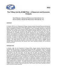
Integrated Power Generation, CO 2<br />
Sequestration & ECBM Vision<br />
Power<br />
Plant<br />
CO 2 /N 2 CH 4<br />
CH 4<br />
CO 2 /N 2<br />
CH 4<br />
CH 4 Deep, Unmineable<br />
Coal<br />
CH 4<br />
CH 4<br />
CH 4<br />
CH 4<br />
CH 4<br />
CO 2 /N 2<br />
4
U.S. CO 2 -ECBM/Sequestration Potential<br />
CO 2<br />
Sequestration Potential (Gt)<br />
ECBM Potential (Tcf)<br />
Basin<br />
Replacement<br />
of Primary<br />
<strong>Recovery</strong><br />
Volume<br />
Injection<br />
for<br />
ECBM in<br />
“Commercial”<br />
Area<br />
Injection for<br />
CO 2<br />
Sequestra-tion<br />
in “Non-<br />
Commer-cial”<br />
Area<br />
Total<br />
(Gt)<br />
%<br />
of<br />
Total<br />
Incremental<br />
<strong>Recovery</strong><br />
in<br />
“Commercial”<br />
Area<br />
Incremental<br />
<strong>Recovery</strong><br />
in<br />
“Non-<br />
Commercial”<br />
Area<br />
Total<br />
(Tcf)<br />
%<br />
of<br />
Total<br />
N. Appalachia<br />
0.8<br />
0.3<br />
2.3<br />
3.4<br />
4%<br />
1.7<br />
13.0<br />
14.7<br />
10%<br />
C. Appalachia<br />
0.1<br />
0.0<br />
0.0<br />
0.1<br />
0%<br />
0.5<br />
0.0<br />
0.5<br />
0%<br />
Black Warrior<br />
0.4<br />
0.1<br />
0.4<br />
0.8<br />
1%<br />
1.0<br />
2.2<br />
3.1<br />
2%<br />
Illinois<br />
Cherokee/ Forest City<br />
0.1<br />
0.4<br />
0.0<br />
0.1<br />
1.2<br />
0.3<br />
1.4<br />
0.9<br />
2%<br />
1%<br />
0.2<br />
0.5<br />
3.8<br />
0.9<br />
4.0<br />
1.4<br />
3%<br />
1%<br />
Arkoma<br />
0.1<br />
0.0<br />
0.0<br />
0.1<br />
0%<br />
0.4<br />
0.1<br />
0.5<br />
0%<br />
Gulf Coast<br />
0.7<br />
0.4<br />
0.9<br />
1.9<br />
2%<br />
0.7<br />
1.7<br />
2.4<br />
2%<br />
San Juan<br />
7.0<br />
2.3<br />
1.1<br />
10.4<br />
12%<br />
11.4<br />
4.3<br />
15.7<br />
10%<br />
Raton<br />
0.4<br />
0.1<br />
0.0<br />
0.6<br />
1%<br />
1.4<br />
0.1<br />
1.5<br />
1%<br />
Piceance<br />
0.5<br />
0.3<br />
1.5<br />
2.4<br />
3%<br />
3.6<br />
10.5<br />
14.0<br />
9%<br />
Uinta<br />
1.6<br />
0.3<br />
0.0<br />
1.9<br />
2%<br />
0.1<br />
0.2<br />
0.3<br />
0%<br />
Greater Green River<br />
3.0<br />
1.3<br />
3.5<br />
7.9<br />
9%<br />
3.5<br />
15.0<br />
18.5<br />
12%<br />
Hanna-Carbon<br />
1.4<br />
0.6<br />
1.0<br />
3.0<br />
3%<br />
1.5<br />
2.4<br />
3.9<br />
3%<br />
Wind River<br />
0.8<br />
0.3<br />
0.3<br />
1.4<br />
2%<br />
0.8<br />
0.6<br />
1.5<br />
1%<br />
Powder River<br />
3.3<br />
1.8<br />
8.5<br />
13.6<br />
15%<br />
3.4<br />
16.2<br />
19.6<br />
13%<br />
Western Washington<br />
0.7<br />
0.3<br />
1.3<br />
2.3<br />
3%<br />
0.7<br />
2.9<br />
3.6<br />
2%<br />
Alaska<br />
18.0<br />
8.1<br />
11.7<br />
37.7<br />
42%<br />
19.2<br />
27.8<br />
47.0<br />
31%<br />
TOTALS<br />
39.3<br />
16.3<br />
34.0<br />
89.8<br />
100%<br />
50.6<br />
101.7<br />
152.2<br />
100%<br />
5
Outline<br />
• Introduction<br />
• ECBM Process<br />
• Pilot Projects<br />
• Economics<br />
• Closing Remarks<br />
6
Gas Storage in Coal<br />
(CBM 101)<br />
• Dual-porosity system (matrix and cleats)<br />
• Gas stored by adsorption on coal surfaces within<br />
matrix (mono-layer of gas molecules, density<br />
approaches that of liquid)<br />
• 1 lb coal (15 in 3 ) contains 100,000 – 1,000,000 ft 2<br />
of surface area<br />
• Pore throats of 20 –500 angstrom<br />
• Production by desorption, diffusion and Darcy<br />
flow (3 D’s of CBM production)<br />
7
Example Coal Sorption Isotherms<br />
700.0<br />
600.0<br />
CO 2<br />
/CH 4 ratio = 2:1<br />
N 2<br />
/CH 4<br />
ratio = 0.5/1<br />
San Juan Basin coal<br />
Carbon Dioxide<br />
Absolute Adsorption (SCF/ton)<br />
500.0<br />
400.0<br />
300.0<br />
200.0<br />
CO 2<br />
/N 2<br />
ratio = 4:1<br />
<strong>Methane</strong><br />
Nitrogen<br />
100.0<br />
0.0<br />
0 200 400 600 800 1000 1200 1400 1600 1800 2000<br />
Pressure (psia)<br />
8
Variability of CO 2 /CH 4 Ratio<br />
CO2/CH4 Sorption Ratio vs Coal Rank<br />
CO2/CH4 Ratio<br />
14<br />
12<br />
10<br />
8<br />
6<br />
4<br />
2<br />
0<br />
Sub HV HVA MV LV<br />
y = 2.5738x -1.5649<br />
R 2 = 0.9766<br />
0.36 0.56 0.76 0.96 1.16 1.36 1.56 1.76 1.96<br />
Coal Rank, Vro (%)<br />
100 psi<br />
1000 psi<br />
3000 psi<br />
9
N 2 -ECBM <strong>Recovery</strong> Mechanism<br />
• Inject N 2 into cleats.<br />
• Due to lower adsorptivity, high percentage of N 2<br />
remains free in cleats:<br />
‣Lowers CH 4 partial pressure<br />
‣Creates compositional disequilibrium between sorbed/free gas<br />
phases<br />
• <strong>Methane</strong> “stripped” from coal matrix into cleat<br />
system.<br />
• <strong>Methane</strong>/nitrogen produced at production well.<br />
• Rapid N 2 breakthrough expected.<br />
10
CO 2 -ECBM <strong>Recovery</strong> Mechanism<br />
• Inject CO 2 into cleats.<br />
• Due to high adsorptivity, CO 2 preferentially<br />
adsorbed into coal matrix.<br />
‣<strong>Methane</strong> displaced from sorption sites.<br />
• <strong>Methane</strong> produced at production well.<br />
• Efficient displacement process – slow CO 2<br />
breakthrough.<br />
11
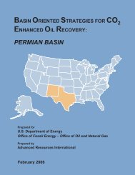
Modeling Sensitivity Study<br />
1 2<br />
3<br />
• San Juan Basin setting<br />
(3000 ft, 40 ft coal, 10 md).<br />
• Inject C0 2 and N 2 at rates<br />
of 10 Mcfd/ft, 25 Mcfd/ft<br />
and 50 Mcfd/ft.<br />
• 15 year period.<br />
4<br />
Quarter 5-Spot Well Pattern<br />
5<br />
12
Gas Production Response – N 2 Injection<br />
10000<br />
70<br />
60<br />
Gas Rate, Mscfd<br />
1000<br />
Incremental Recoveries:<br />
10 Mcfd/ft – 0.6 Bcf (21%)<br />
25 Mcfd/ft – 1.1 Bcf (39%)<br />
50 Mcfd/ft – 1.6 Bcf (57%)<br />
50<br />
40<br />
30<br />
20<br />
Nitrogen Content, %<br />
10<br />
100<br />
0 1000 2000 3000 4000 5000<br />
0<br />
Days<br />
Base Case Injection @ 25 Mcfd/ft<br />
Injection @ 10 Mcfd/ft<br />
Injection @ 50Mcfd/ft<br />
13
Gas Production Response – CO 2 Injection<br />
10000<br />
Gas Rate, Mscfd<br />
1000<br />
Incremental Recoveries:<br />
10 Mcfd/ft – 0.1 Bcf (4%)<br />
25 Mcfd/ft – 0.4 Bcf (14%)<br />
50 Mcfd/ft – 0.8 Bcf (29%)<br />
•No CO 2<br />
breakthrough<br />
•CO 2<br />
/CH 4<br />
ratio is 2:1 whereas N 2<br />
/CH 4<br />
ratio is 0.5/1<br />
100<br />
0 1000 2000 3000 4000 5000<br />
Days<br />
Base Case Injection @ 25 Mcfd/ft<br />
Injection @ 10 Mcfd/ft<br />
Injection @ 50Mcfd/ft<br />
14
Outline<br />
• Introduction<br />
• ECBM Process<br />
• Pilot Projects<br />
• Economics<br />
• Closing Remarks<br />
15
Only Two “Large-Scale” Field<br />
Tests Exists Worldwide<br />
• San Juan Basin, Upper Cretaceous Fruitland Coal<br />
• Allison Unit<br />
• Burlington <strong>Resources</strong><br />
• Carbon dioxide injection<br />
• 16 producers<br />
• 4 injectors<br />
• 1 pressure observation well<br />
• Tiffany Unit<br />
• BP<br />
• Nitrogen injection<br />
• 34 producers<br />
• 12 injectors<br />
16
Field Sites, San Juan Basin<br />
LA PLATA CO.<br />
ARCHULETA<br />
COLORADO<br />
NEW MEXICO<br />
Durango<br />
Florida River<br />
Plant<br />
F A I R W A Y<br />
N2 Pipeline<br />
Tiffany Unit<br />
Pagosa<br />
Springs<br />
San Juan<br />
Basin Outline<br />
Allison Unit<br />
Dulce<br />
Aztec<br />
Farmington<br />
Bloomfield<br />
R<br />
17
Allison Unit Base Map<br />
61<br />
104<br />
111<br />
12M<br />
106<br />
112<br />
101<br />
130<br />
142<br />
114<br />
POW#2<br />
115<br />
108<br />
131<br />
141<br />
113<br />
140<br />
132<br />
143<br />
120<br />
102<br />
121<br />
119<br />
62<br />
18
Well Configurations<br />
Injector<br />
Producer<br />
19
Individual Well Gas Rate, Mcf/d<br />
Allison Production History<br />
2,000,000<br />
1,800,000<br />
1,600,000<br />
1,400,000<br />
16 producers, 4 injectors, 1 POW<br />
Injectivity reduction<br />
Line pressures reduced, wells recavitated, wells<br />
reconfigured, onsite compression installed<br />
Peak @ +/- 57 MMcfd<br />
4,000<br />
3,500<br />
3,000<br />
1,200,000<br />
2,500<br />
1,000,000<br />
2,000<br />
800,000<br />
1,500<br />
600,000<br />
400,000<br />
Gas Rate, Mcf/mo<br />
CO2 Injection Rate, Mcf/mo<br />
1,000<br />
Well Gas Rate, Mcf/d<br />
200,000<br />
+/- 3 1/2 Mcfd<br />
500<br />
0<br />
0<br />
Jan-89<br />
Jul-89<br />
Jan-90<br />
Jul-90<br />
Jan-91<br />
Jul-91<br />
Jan-92<br />
Jul-92<br />
Jan-93<br />
Jul-93<br />
Jan-94<br />
Jul-94<br />
Jan-95<br />
Jul-95<br />
Jan-96<br />
Jul-96<br />
Jan-97<br />
Jul-97<br />
Jan-98<br />
Jul-98<br />
Jan-99<br />
Jul-99<br />
Jan-00<br />
Jul-00<br />
Jan-01<br />
Jul-01<br />
Date<br />
20<br />
Rates, Mcf/mo
Site Description<br />
Property<br />
Value<br />
Average Depth to Top Coal<br />
3100 feet<br />
No. Coal Intervals<br />
3 (Yellow, Blue, Purple)<br />
Average Total Net Thickness<br />
Permeability<br />
43 feet<br />
100 md<br />
Yellow – 22 ft<br />
Blue – 10 ft<br />
Purple – 11 ft<br />
Initial Pressure<br />
1650 psi<br />
Temperature<br />
120°F<br />
21
Progression of CO 2 Displacement<br />
(@ mid-2002)<br />
Face<br />
Cleat<br />
Butt<br />
Cleat<br />
N<br />
22
Incremental <strong>Recovery</strong><br />
Case<br />
Total <strong>Methane</strong><br />
<strong>Recovery</strong> (Bcf)<br />
Incremental<br />
<strong>Recovery</strong><br />
(Bcf)<br />
Total CO 2<br />
Injection<br />
(Bcf)<br />
CO 2<br />
Production<br />
(Bcf)<br />
CO 2<br />
/CH 4<br />
Ratio<br />
W/o CO 2<br />
injection<br />
100.5*<br />
n/a<br />
n/a<br />
n/a<br />
n/a<br />
W/CO 2<br />
injection<br />
102.1<br />
1.6<br />
6.4**<br />
1.2<br />
3.2<br />
*6.3 Bcf/well<br />
** 20 Mcfd/ft<br />
Small incremental recovery due to limited injection volumes.<br />
INJECTIVITY IS CRITICAL!<br />
Note: OGIP for model = 152 Bcf.<br />
23
Tiffany Unit Base Map<br />
Previous Study Area<br />
Producer-to-Injector<br />
Conversions<br />
24
Well Configurations<br />
Producer Well<br />
Multiple Injector Wells<br />
25
Tiffany Production History<br />
1,000,000<br />
34 producers, 12 injectors<br />
Peak @ 26 MMcfd<br />
+/- 5MMcfd<br />
100,000<br />
10,000<br />
Injection initiated<br />
1,000<br />
100<br />
Gas Rate, Mcf/mo<br />
N2 Injection Rate,<br />
Mcf/mo<br />
Suspension periods<br />
Max Inj Rate = 26 MMcfd<br />
Sep-83<br />
Sep-84<br />
Sep-85<br />
Sep-86<br />
Sep-87<br />
Sep-88<br />
Sep-89<br />
Sep-90<br />
Sep-91<br />
Sep-92<br />
Sep-93<br />
Sep-94<br />
Sep-95<br />
Sep-96<br />
Sep-97<br />
Sep-98<br />
Sep-99<br />
Sep-00<br />
Sep-01<br />
Sep-02<br />
Date<br />
26<br />
Gas Rates, Mcf/mo
Site Description<br />
Property<br />
Value<br />
Average Depth to Top Coal (A)<br />
2970 feet<br />
No. Coal Intervals<br />
7 total (A, A2, B, C, D, E, F)<br />
4 main (B, C, D, E)<br />
Average Net Thickness<br />
Permeability<br />
47 feet<br />
Progression of N 2 Displacement<br />
(@ mid-2002)<br />
Face<br />
Cleat<br />
Butt<br />
Cleat<br />
N<br />
28
Current Field Results<br />
(through mid-2002)<br />
Case<br />
Total <strong>Methane</strong><br />
<strong>Recovery</strong> (Bcf)<br />
Incremental<br />
<strong>Recovery</strong><br />
(Bcf)<br />
Total N 2<br />
Injection<br />
(Bcf)<br />
N 2<br />
Production<br />
(Bcf)<br />
N 2<br />
/CH 4<br />
Ratio<br />
W/o N 2<br />
injection<br />
*35.3<br />
n/a<br />
n/a<br />
n/a<br />
n/a<br />
W/N 2<br />
injection<br />
45.8<br />
10.5<br />
14.0**<br />
1.3<br />
1.2<br />
*1.0 Bcf/well<br />
** 46 Mcfd/ft<br />
At N 2<br />
/CH 4<br />
ratio of 0.75:1 and reproduced volume<br />
of 25%, ultimate incremental recovery estimated<br />
to be +/- 14 Bcf or 40% improvement over primary.<br />
Note: OGIP for model = 438 Bcf.<br />
29
Summary of Field Results<br />
• Field results are in general agreement with theoretical<br />
understanding; reservoir models can reasonably<br />
replicate/predict field behavior.<br />
• Low-incremental recovery with CO 2 injection at<br />
Allison due to low injection volumes.<br />
• CO 2 injectivity key success driver; strong evidence that<br />
coal permeability (and injectivity) reduced with CO 2<br />
injection.<br />
• Incremental recoveries with N 2 injection at Tiffany<br />
currently; estimated to provide 40% improvement over<br />
primary.<br />
30
Outline<br />
• Introduction<br />
• ECBM Process<br />
• Pilot Projects<br />
• Economics<br />
• Closing Remarks<br />
31
Hypothetical Field Setting<br />
(US onshore)<br />
Example CBM Basin<br />
Well Injection Pattern<br />
(4 Sections)<br />
Sec. 6 Sec. 5<br />
Sec.7 Sec. 8<br />
Conventional <strong>Recovery</strong> – 48 Bcf<br />
(2.5 Bcf/well)<br />
Incremental <strong>Recovery</strong> – 16 Bcf<br />
(1 Bcf/well)<br />
32
Economics of CO 2 ECBM<br />
US $/Mcf<br />
Hub Gas Price $3.00<br />
Less: Basin Differential ($0.30)<br />
BTU Adjustment (@ 5%) ($0.15)<br />
Wellhead Netback $2.55<br />
Less: Royalty/Prod. Taxes (20%) ($0.51)<br />
O&M/Gas Processing ($0.50)<br />
Gross Margin $1.54<br />
Capital Costs (1) ($0.25)<br />
CO 2<br />
Costs (@ ratio of 3.0 to 1) (2) ($0.90)<br />
Net Margin $0.39<br />
(1) Capital Costs = $500,000 *4 (inj wells) = $2,000,000/16 Bcfg<br />
= $0.13/Mcfg * 2 = $0.25/Mcfg<br />
(2) CO 2 Costs = $0.30/Mcf * 3.0 = $0.90/Mcf (CO 2 )<br />
33
Economics of N 2 ECBM<br />
US $/Mcf<br />
Hub Gas Price $3.00<br />
Less: Basin Differential ($0.30)<br />
BTU Adjustment (@5%) ($0.15)<br />
Wellhead Netback $2.55<br />
Less: Royalty/Prod. Taxes (20%) ($0.51)<br />
O&M/Gas Processing ($1.00) (double over CO 2<br />
case)<br />
Gross Margin $1.04<br />
Capital Costs (1) ($0.25)<br />
N 2 Costs (@ ratio of 0.5 to 1) (2) ($0.30)<br />
Net Margin $0.49<br />
(1) Capital Costs = $500,000 * 4 (inj. wells) = $2,000,000/16 Bcfg<br />
= $0.13/Mcfg * 2 = $0.25/Mcfg<br />
(2) N 2<br />
Costs = $0.60/Mcf * 0.5 = $0.30/Mcf (N 2<br />
)<br />
34
ECBM Economic Considerations<br />
• N 2 – ECBM appears favorable, but early<br />
breakthrough requires costly post-production gas<br />
processing.<br />
• CO 2 - ECBM also appears favorable, but<br />
maintaining injectivity a key success driver.<br />
• More experience required to validate & optimize<br />
economic performance.<br />
• CO 2 /N 2 mixture may be optimum.<br />
‣ High N 2 concentrations early for rapid methane recovery<br />
‣ Increasing CO 2 concentrations later for efficient methane<br />
displacement.<br />
35
Outline<br />
• Introduction<br />
• ECBM Process<br />
• Pilot Projects<br />
• Economics<br />
• Closing Remarks<br />
36
Closing Remarks<br />
• ECBM recovery appears to hold considerable<br />
promise; on the verge of commerciality with a bright<br />
future.<br />
• CO 2 sequestration economic drivers (carbon credits)<br />
will substantially improve financial performance and<br />
accelerate commercial adoption.<br />
• In U.S., CO 2 -ECBM/sequestration potential is<br />
substantial; recently assessed at 90 Gt CO 2 and 150<br />
Tcf of incremental gas recovery.<br />
37
Closing Remarks<br />
• More work is needed to economically optimize the process.<br />
‣N 2 /CO 2 mixtures<br />
‣CO 2 injectivity<br />
‣Spacing, patterns, rates, etc.<br />
‣Reservoir settings (coal rank)<br />
• Reservoir response is generally consistent with theoretical<br />
understanding of CO 2 /N 2 processes.<br />
‣Reasonable predictions of reservoir response possible.<br />
‣Informed investment decisions.<br />
• Acknowledgements:<br />
‣U.S. Department of Energy<br />
‣Burlington <strong>Resources</strong><br />
‣BP America<br />
• For more information:<br />
www.coal-seq.com<br />
38
<strong>Enhanced</strong> <strong>Coalbed</strong> <strong>Methane</strong> <strong>Recovery</strong><br />
presented by:<br />
Scott Reeves<br />
<strong>Advanced</strong> <strong>Resources</strong> International<br />
Houston, TX<br />
SPE Distinguished Lecture Series<br />
2002/2003 Season<br />
39<br />
<strong>Advanced</strong> <strong>Resources</strong> International
Well #132 Performance<br />
4000<br />
3500<br />
CH 4 <strong>Recovery</strong> w/o CO 2 injection = 6.1 Bcf<br />
CH 4 <strong>Recovery</strong> w/ CO 2 injection = 6.9 Bcf<br />
CH 4 Incremental <strong>Recovery</strong> = 0.8 Bcf<br />
3000<br />
CH4 Rate, Mscf<br />
2500<br />
2000<br />
1500<br />
1000<br />
500<br />
0<br />
0 1000 2000 3000 4000 5000 6000 7000 8000 9000<br />
Days<br />
CO2 Injection<br />
No CO2 Injection<br />
40
Nitrogen Content of Produced Gas<br />
14<br />
12<br />
Average = 12.3 %<br />
10<br />
No. Wells<br />
8<br />
6<br />
4<br />
2<br />
0<br />
< 1 1 - 10 10 - 20 20 - 30 30 - 40 40 - 50 > 50<br />
Last N2 Concentration (%)<br />
41
Matrix Shrinkage/Swelling<br />
Source: “An Investigation of the Effect of Gas Desorption on Coal Permeability”, paper 8923, 1989 <strong>Coalbed</strong> <strong>Methane</strong> Symposium.<br />
42
Relevant Formulas*<br />
Pressure-Dependence<br />
Shrinkage/Swelling<br />
φ = φ i + φ i C p (P-P i ) + (1 - φ i ) C m dP i<br />
dC i<br />
(C-C i )<br />
k =<br />
n<br />
φ n = +/- 3<br />
φi<br />
*Used in COMET2. Alternative formulation presented by Palmer & Mansoori; SPE 36737, 1996.<br />
43
Permeability Changes with Net Stress, Gas<br />
Concentration, and Sorptive Capacity<br />
Matrix Shrinkage<br />
Pressure Dependence<br />
250<br />
Permeability, md<br />
200<br />
150<br />
100<br />
50<br />
Sorption Capacity<br />
<strong>Methane</strong><br />
Carbon Dioxide<br />
0<br />
0 500 1000 1500 2000 2500 3000 3500<br />
Pressure, psi<br />
44
Typical Injection Profile,<br />
Allison Unit<br />
Well #143<br />
60000<br />
2500<br />
2300<br />
50000<br />
2100<br />
Pressure<br />
40000<br />
30000<br />
CO2, Mcf/mo<br />
1900<br />
1700<br />
1500<br />
20000<br />
10000<br />
0<br />
Jan-89<br />
Jul-89<br />
Jan-90<br />
Jul-90<br />
Jan-91<br />
Jul-91<br />
Jan-92<br />
Jul-92<br />
Jan-93<br />
Jul-93<br />
Jan-94<br />
Jul-94<br />
Jan-95<br />
Jul-95<br />
Jan-96<br />
Jul-96<br />
Jan-97<br />
Jul-97<br />
Jan-98<br />
Jul-98<br />
Jan-99<br />
Jul-99<br />
Jan-00<br />
Jul-00<br />
Rate<br />
BHP, psi<br />
1300<br />
1100<br />
900<br />
700<br />
500<br />
Date<br />
45
Permeability History for Injector<br />
250<br />
Start<br />
Permeability, md<br />
200<br />
150<br />
100<br />
50<br />
Continued<br />
Injection<br />
Depletion<br />
Displace w/ CO2<br />
0<br />
0 500 1000 1500 2000 2500 3000 3500<br />
Pressure, psi<br />
46
CO 2 Sorption Behavior<br />
(Pc=1073psi, Tc=88ºF)<br />
Source: SPE 29194: “Adsorption of Pure <strong>Methane</strong>, Nitrogen and Carbon Dioxide and their Binary Mixtures on Wet Fruitland Coal”, 1994.<br />
47
Pure Gas Gibbs Adsorption on<br />
Tiffany Coals at 130° F<br />
Gibbs Adsorption (SCF/ton)<br />
600.0<br />
500.0<br />
400.0<br />
300.0<br />
200.0<br />
N abs<br />
= N Gibbs<br />
1- ρ gas<br />
ρ ads<br />
N2 on Mixed Coal<br />
CH4 on Well #1<br />
CH4 on Well #10<br />
CH4 on Mixed Coal<br />
CO2 on Mixed Coal<br />
100.0<br />
0.0<br />
0 200 400 600 800 1000 1200 1400 1600 1800 2000<br />
Pressure (psia)<br />
48
CO 2 Absolute Adsorption on Tiffany<br />
Mixed Coal Sample Using Different<br />
Adsorbed-Phase Densities<br />
700<br />
600<br />
Aboslute Adsorption (SCF/ton)<br />
500<br />
400<br />
300<br />
200<br />
100<br />
Adsorbed Phase Density(g/cc)<br />
1.18<br />
1.25<br />
1.40<br />
Saturated liquid density at triple point<br />
ZGR estimate<br />
Graphical estimate<br />
0<br />
0 200 400 600 800 1000 1200 1400 1600 1800 2000<br />
Pressure (psia)<br />
49
Multi-Component Sorption<br />
Behavior<br />
Extended Langmuir Theory<br />
V Li p i<br />
, i = 1, 2, 3,…, n.<br />
C i (p i ) =<br />
n<br />
p<br />
p<br />
Li 1 + Σ<br />
j=1<br />
p L<br />
Other Langmuir Models:<br />
Equations of State:<br />
Simplified Local Density Models:<br />
Loading Ratio Correlation (LRC), Real Adsorbed Solution (RAS),<br />
Ideal Adsorbed Solution (IAS)<br />
Van der Walls (VDW), Eyring, Zhou-Gasem-Robinson (EOS-S, PGR)<br />
Flat Surface (PR-SLD), Slit (PR-SLD)<br />
50
Accuracy of Model Predictions for<br />
Pure Gas Adsorption<br />
Quality of Fit, % AAD, for Specified Model<br />
Component<br />
Langmuir<br />
LRC<br />
(n = 0.9)<br />
ZGR-EOS<br />
Experimental<br />
Error<br />
<strong>Methane</strong><br />
2.6<br />
2.3<br />
3.0<br />
3.0<br />
Nitrogen<br />
3.5<br />
2.3<br />
2.3<br />
6.0<br />
Carbon<br />
Dioxide<br />
2.0<br />
1.8<br />
2.1<br />
7.0<br />
51
Accuracy of Model Predictions for<br />
Binary/Ternary Gas Adsorption<br />
(based on pure-gas adsorption data)<br />
LRC<br />
Mixture,<br />
Langmuir<br />
(n=0.9)<br />
ZGR-EOS<br />
Experimental Error<br />
(Feed Mole %)<br />
% AAD<br />
% AAD<br />
% AAD<br />
% AAD<br />
CH 4 –N 2 :<br />
CH 4 (50%)<br />
N 2 (50%)<br />
Total<br />
15.8<br />
6.2<br />
12.2<br />
12.0<br />
9.3<br />
8.2<br />
11.9<br />
10.0<br />
11.5<br />
7.0<br />
17.0<br />
7.0<br />
CH 4 –CO 2 :<br />
CH 4 (40%)<br />
CO 2 (60%)<br />
Total<br />
25.9<br />
9.0<br />
1.2<br />
21.0<br />
10.5<br />
2.2<br />
27.0<br />
10.4<br />
1.4<br />
7.0<br />
6.0<br />
4.0<br />
N 2 –CO 2 :<br />
N 2 (20%)<br />
CO 2 (80%)<br />
Total<br />
44.9<br />
5.2<br />
3.5<br />
37.3<br />
5.7<br />
3.8<br />
48.7<br />
4.9<br />
3.5<br />
29.0<br />
6.0<br />
5.0<br />
N 2 –CH 4 -CO 2 :<br />
N 2 (10%)<br />
CH 4 (40%)<br />
CO 2 (50%)<br />
Total<br />
47.8<br />
20.7<br />
13.2<br />
2.9<br />
44.5<br />
5.2<br />
15.8<br />
5.4<br />
55.9<br />
21.6<br />
17.6<br />
4.3<br />
14.0<br />
27.0<br />
5.0<br />
5.0<br />
52