Lupton Industrial Windows
Lupton Industrial Windows
Lupton Industrial Windows

Create successful ePaper yourself
Turn your PDF publications into a flip-book with our unique Google optimized e-Paper software.
- v I-:<br />
r 1.7
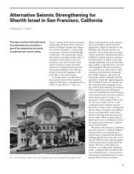
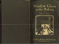
LUPTON<br />
INDUSTRIAL<br />
WINDOWS<br />
PRODUCTS IU'nDoIU I<br />
~<br />
MICHAEL FLYNN<br />
MANUFACTURING CO.<br />
i^itccefiom<br />
tc David <strong>Lupton</strong>'s Sons Co. mz<br />
Allegheny Ave. at Tulip St.<br />
Philadelphia, Pa.
established window line, are guidedby the<br />
quality, product will find ready acceptance<br />
it is designed to benefit.<br />
In the following pages is presented information to assist you in the preparation of details<br />
and specifications. Details are typical, showing construction and general principles underlying<br />
satisfactory installation. To insure accurate estimates, all products should be accurately<br />
listed and located either in schedules on plans or in specifications. If more than one type<br />
of product or type of hardware is desired, each type should be separately listed and located<br />
or otherwise clearly designated.<br />
Where preferred, we will erect any of our products, but stock items such as Pivoted, Basement<br />
and Residence Casement <strong>Windows</strong> are usually more economically erected by the general<br />
building contractor. All other <strong>Lupton</strong> Products, however, because of their special application<br />
should be erected by our own forces to assure satisfactory installation and service. There<br />
is an erection specification prepared for each product which should be exactly followed and<br />
which will secure satisfactory use of product at reasonable cost.<br />
t<br />
><br />
Putty<br />
Calking<br />
Glazing should be done by experienced steel window glaziers. We suggest that glazing of<br />
Pivoted, Basement, Commercial and Architectural Projected and Residence Casement<br />
<strong>Windows</strong> be handled by others. However, we will arrange for glazing of any of our products<br />
when this is preferred. When glazing, the glass should be bedded in putty to form a watertight<br />
seal and to prevent glass touching metal.<br />
Always specify steel window putty for glazing steel windows. Ordinary putty intended for<br />
wood windows will not be satisfactory as it dries hard and cracks away from steel. Because<br />
various climates require variations in the ingredients of satisfactory putty, we recommend<br />
that putty be obtained from local sources. When this is impossible, putty may be secured<br />
from the Michael Flynn Mfq. Co. or its sales representatives.<br />
See calking specification for each product. The calking cement furnished by us is elastic,<br />
dark qray in color and will not stain masonry. When we apply calking, application is for<br />
weathertightness only and is understood not to be a finished pointing job. Erector spreads<br />
cement on edge of window and strikes off excess after window is set in place.<br />
A<br />
A<br />
Painting<br />
All <strong>Lupton</strong> Products are given a shop coat of paint before shipment. After glazing, no painting<br />
should be done until putty has set (about-three weeks). It is advisable to hold the painting<br />
for cleaning plaster or other foreign matter from the weathering<br />
in order that it may not be painted over and cause imperfect contact.
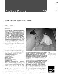
ARCHITECTURAL<br />
PROJECTED WINDOWS<br />
I<br />
Work Included<br />
Some buildings, or parts of buildings, because of limits in cost or because of other<br />
restrictions, will not permit the use of casement windows. In such cases, <strong>Lupton</strong><br />
Architectural Projected <strong>Windows</strong>, made of medium weight sections, will often fill the<br />
requirements of good ventilation and lighting with entire satisfaction.<br />
Made in standard sizes for outside or inside glazing. Window dimensions, glass<br />
sizes, and wall details are the same for both inside and outside glazed windows.<br />
1. Furnish and install where shown on drawings, <strong>Lupton</strong> Steel<br />
Architectural Projected <strong>Windows</strong>, manufactured by Michael Flynn<br />
Mfa. Co., Philadelphia, Pb.<br />
Materials<br />
2. Frame members ahall be heavy, specially designed, solid<br />
steel, unequal leg channel section*.<br />
3. Vsntilalor tnarnhrs shall be specially designed, solid ateel<br />
angle sections.<br />
4 Muntin8 shall be specially designed, solid steel cruciform<br />
section 1% in. deep.<br />
5. Vertical mullionm &all be formed steel plate.<br />
N*:-Structurtl steel ~im&ei-~ forming Imposts are not<br />
f~rn)d)Ç by the window nraaiiiacturer.<br />
for outside glazing (or ~pecify:<br />
with gwng angles).<br />
7. B~hlF'ramat and Ventilabrs'sfall be antembid by tenoned,<br />
riveid and ~fclw,! jcintp'at ttb corners. Continuous, two-point<br />
flat &ntact weitlmtng dialh~e prenddad.betw^h ventilators and<br />
fnunae.<br />
9. Vertical Mullioiw and Edits Mr attachfit shall b4providd '<br />
where two or iporeytindow$ yfe placed side by side in Ah o^>ef)ing.<br />
10. Each ventilator .hall-b
PULL-DW-WG-W358<br />
Wounkd on fq rail of open - out<br />
vendilab for pok operaiion<br />
Used in conjunction wifh Ring<br />
Handle fhom below.<br />
10CKIN~-HANDLE-II! 328<br />
For pole operation of open-outa{<br />
bottom venlildor~ beyond<br />
reach from floor -+-,<br />
1.OCK1t N GP H A N DlL'E e t t ' 26-6<br />
Far, all open-out-at- bottom veniilk!or/<br />
witkin reach from floor<br />
fhown mounfed on meeiin
i<br />
3EG G , I:-<br />
THRU I '.<br />
5EC.w<br />
JAMB<br />
5EC-H<br />
KoTHRU SEC- L-THRU<br />
MULLION MUNTFN<br />
IAUUFACTUR IIcHAE L'F/YNN N ~ c <br />
-<br />
PLATEEN<br />
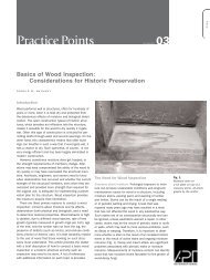
UPTON DETAILJ-OUTJIDE BLAZED 402<br />
~OW.PRODK~<br />
LUPTOI!*ARCHITECTURAL-PROJECTED<br />
*WINDOWS APiiiL-i936
SECTION *THRU*JAM5<br />
OF FI X ED -'.LIGHT
*ELL-VATION*<br />
VENT1 LATORJ-CLCJE-D<br />
SECTION*<br />
VE'NTJ -OPtN<br />
VENTILATOU-CLOSED<br />
JkCTION-<br />
VENT3 OPEN
JECTICN e T H U l u HE-AD<br />
JE-CTI ON -THR.U-JAMB - OF-<br />
PROJECTED - IN -AT-TOP -V&NTI IATO
COMMERCIAL PROJECTED<br />
AND PIVOTED WINDOWS<br />
These two types of windows are almost identical in construction, the difference is in<br />
the operation (or hanging) of the movable portion or ventilator.<br />
Both types have a wide range of application though mostly used for industrial<br />
buildings and buildings of like character. Both types can be screened.<br />
Work Included<br />
1. Furnish where shown on drawings <strong>Lupton</strong> Steel ConuneTcial<br />
Projaded <strong>Windows</strong> (or Lupkxa Stwl Pivoted <strong>Windows</strong>) manufacturd<br />
by Michael Plynn Mfg. Co., Philadelphia, Pa.<br />
Materials<br />
2. Ventilator and frame members, muntins and mullions shall<br />
be of hot rolled steel.<br />
3. Frame member shall be special angle section, muntins shall<br />
be cruciform section 1% in. deep, and mullions shall be T bars,<br />
Note:-Structural steel members forming imposts are not<br />
furnished by the window manufacturer.<br />
Construction<br />
4. All Commercial Projected (or Pivoted) <strong>Windows</strong> shall be<br />
designed for inside glazing.<br />
5. Both frames and ventilators shall be assembled by tenoned,<br />
riveted joints at corners. (Commercial Projected Ventilators shall<br />
have corners welded in addition to riveting.) Continuous two<br />
point, flat weathering contact shall be provided between frame and<br />
ventilator.<br />
6. All muntins shall be continuous thru, and interlocked at,<br />
their intersections. They shall be attached to frame or ventilator<br />
members by tenoning and riveting.<br />
7. Vertical mullions shall be provided where two or more units<br />
are to be placed side by side in one opening.<br />
8. Where windows are anchored to steel structure, furnish<br />
clips of types to suit conditions.<br />
9. . Furnish anchor clips at sill, at least one clip for each two<br />
lights in the width of a unit.<br />
10. Where hardware is to be attached to bottom rail of ventilator,<br />
a clip for this purpose shall be riveted to ventilator.<br />
11. COMMERCIAL PROJECTED WINDOWS shall have ventilators<br />
accurately pivoted at sides on two steel arms attached to<br />
window frames by steel arm blocks. Each ventilator shall be<br />
equipped with two rustproofed Hat, steel springs and two brass<br />
friction shoes. Friction shoes shall slide vertically in the channels<br />
formed by the side weathering of the ventilators with sufficient<br />
friction to hold the ventilators in any open position up to the limit<br />
of their movement and to prevent rattling.<br />
12. PIVOTED WINDOWS shall have ventilators horizontally<br />
pivoted. Pivots shall be located two inches above center line of<br />
ventilator. Pivot plates shall be integral with the side weathering.<br />
Pivot pins shall be %@-in. iron rivets fastened with cotter pins.<br />
Specifications<br />
Hardware<br />
13. All hardware shall be shippd unattflchad, carefully<br />
packed.<br />
14. COMMERCIAL PROJECTED WINDOWS shall have the<br />
following malleable iron hardware:<br />
Por open out ventilator-Ring handle and pull down ring.<br />
For open in ventilators within reach-Locking<br />
For opw in ventilators beyond reach-Spring<br />
handle.<br />
catch.<br />
IS. PIVOTED WINDOWS shall have the following hardware:<br />
Pro~ide atuy bar and clip far vantiigtors wiwn reach from floor,<br />
provide spring catch, chain, chain roller guide and clip for vanh<br />
beyond r6ach from floor.<br />
Erection<br />
16. All Commercial Projected (or Pivdod) <strong>Windows</strong> shalt be<br />
erected by the window corrtractac (or date by whom) in prepared<br />
owing*.<br />
Note:-Setting in preptruuj openings is the recowended prac-<br />
Koe. Include in the masonry specifications ihç all masonry<br />
opening6 shall bo' accurately congtructd ih accordance with thd<br />
inatçUaÇ for Lupbn Commercial Projected (or Pivoted)<br />
w~&s. At1 routing, poinhg, sb:., should be dome by tba<br />
tn&aon contntcJfy alter the windows ate set. Note:-% page 3.<br />
17. ~$dow* &ill be set @umb and true, propqriy aligned and<br />
~lputbty aBh& usd all ventilahs properly adjuitad before ,<br />
f
Hardware<br />
Standard hardware is steel or malleable iron,<br />
painted. Bronze hardware may be had if desired<br />
but must be clearly specified. See note at end<br />
of specifications.<br />
At right. Locking Handle No. 141. Malleable<br />
iron, painted. Used on Projected out at bottom<br />
Ventilators.<br />
At right. Looking Handle No. 308. Used<br />
within reach from door on Projected in at top<br />
Ventilators. Spring Catch No. 509 is used<br />
beyond reach.<br />
At left. Standard<br />
units have upper<br />
ventilator equipped<br />
with Spring Catch<br />
3130, Chain roller<br />
guide 3102 and 10<br />
ft. of chain. Lower<br />
ventilator is<br />
equipped with stay<br />
bar 3115. Where<br />
sill heiaht is aiven<br />
At left. Pull Down Ring No. 4881. Malleable<br />
iron, painted. Used on Projected<br />
out at bottom Ventilators.<br />
At left. Steel Clip No. 3018 attached to<br />
window holds either stay bar or c hah
I<br />
- - -<br />
-<br />
COMMEU-'IAL PROJ K T E D<br />
W/NDQWQ/!ON~ WIDTH<br />
-
STANDARD-END-CUT-FOIL I-AT--HA~c~JTJ- TVPM-345<br />
MULLIOtJJ'<br />
(JEE-TABLE -AT- RIGHT)<br />
STW-PROJECT/. I 316' 2-AT-CUT-JTONt- ILU- Ol.<br />
BEfOND- BOTTOM- OP WOOD-/ILLS- WHh<br />
WINDOW/-AND-lJ- W D - NOTCHING- Of *JILL1- \S<br />
OED-IN-THE-JILL. THIJ UUDESHABL E-<br />
TVP6-IS~ALWAV~FURMVH- fURNISHED-OULY-WHEN<br />
E .UNLEAf-OTHMWlJk SPECIFIED.<br />
ifmm<br />
tllCHAE 1-FLYNN<br />
AAMUFACTUKIU~c<br />
PLATEON^<br />
LUPTON MULLIONJ and IMPOJT5 607<br />
MDGW-PHODUOf<br />
LUPTON *PIVOTE D.L COMM'L-P ROJECTED*WINDOWJ<br />
AUIL-j93L
TOP
Jee Paqe 44
ated <strong>Windows</strong> with Underwriters' Labels<br />
p r wire glass is to be<br />
for fire protection it is<br />
w l e to specify Labeled<br />
,_~,w$. This insures that<br />
full measure of safety<br />
i^JQdd is actually secured.<br />
34i
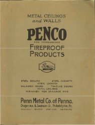
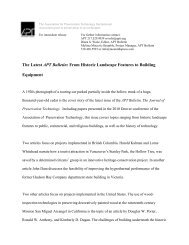
Mechanical Operators for Pivoted and Continuous<br />
<strong>Windows</strong> are available in two general types-tension<br />
type and torsion type. Torsion operators prove<br />
economical in most cases, but where the requirements<br />
exceed the limits of torsion operators a tension<br />
operator is recommended, details of which must<br />
conform to individual requirements.<br />
With torsion operators ventilators are controlled<br />
ay lever arms (Lever Type Operator) or racks and<br />
pinions (Rack and Pinion Operator) mounted on a<br />
horizontal shaft which is supported in brackets<br />
attached to wall or window mullions. Power is applied<br />
to the horizontal shaft through a worm and gear<br />
which also locks the ventilators atthe desired degree<br />
of opening. Worm and gear may be open type or<br />
fully enclosed packed in grease and may be operated<br />
by hand chain, hand wheel or electric motor. Electrical<br />
power usually proves economical only for Rack<br />
and Pinion Operator. Details are given on pages 19<br />
and 20.<br />
Above, With the Lever Type Operators the ventilators are controlled<br />
by operating arms clamped to the horizontal shaft and<br />
connected to the vent by steel vent rode.<br />
At left. Rack and Pinion<br />
Operator. Pinion gears securely<br />
attached to horizontal<br />
shaft operate the steel bar<br />
racks to open and close the<br />
ventilators.<br />
Lever Type Operator - Specifications<br />
Work Included<br />
1. Furnish and install where shown on drawings Lever Type<br />
Operating Device, as supplied by Michael Flynn Mfg. Co.,<br />
Philadelphia, Pa.<br />
Materials and Construction<br />
2. Power shall be a machine cut steel worm operating a gray<br />
cast iron segment worm gear assembled with a gray cast iron<br />
yoke and supporting bracket adapted for rigid attachment to<br />
building construction (or by means of extension clips, to window<br />
mullion). The hub of the segment gear shall be drilled to fit the<br />
power transmission line and shall be tightly secured to it with set<br />
screws so as to rotate the line on the gear axis.<br />
Note:-This will operate runs up to 40 it. on each side of power,<br />
and no more than 12 average size ventilators.<br />
3. Power shaft shall be 1 in. standard black steel pipe joined<br />
into a continuous line by malleable iron clamp couplings.<br />
4. Shaft shall be supported by gray iron (or malleable iron)<br />
brackets attached to the window mullions or to the building<br />
construction.<br />
5. Gray iron (or malleable iron) operating arms, one to each<br />
ventilator, shall be rigidly attached to the shaft.<br />
6. Connection between the operating arm and the ventilator<br />
shall be made by a steel vent rod and a gray iron bracket mounted<br />
on the ventilator. Pivot pins at both ends of the vent rod shall<br />
be brass.<br />
Note:-Specify<br />
desired.<br />
operation by chain or by vertical steel shaft as<br />
7. Chain Operation~Power shall be operated by No. 6 Jack<br />
hand chain, operating over a chain wheel and guided b a guard.<br />
Both wheel and guard shall be gray iron castings. Wheel shall<br />
be accurately drilled, mounted on worm shaft and securely held<br />
by setscrews. Chain shall terminate approximately 2 ft. above<br />
the floor,<br />
Note:-Where building construction makes it impractical to<br />
hang the chain directly vertical from the power (as in monitor<br />
window installations) single and double chain idlers are furnished<br />
if clearly indicated on original drawings and in specifications, and<br />
mentioned in contract for operators.<br />
8. Steel Shaft Operation-Power shall be operated by a vertical<br />
% in. round steel shaft, coupled directly to the worm shaft<br />
with a gray iron coupling. The shaft shall be supported by<br />
adjustable gray iron brackets spaced notover 6 ft. apart, one<br />
bracket always being placed at the lower end of the shaft, approximately<br />
4 it. above the floor.<br />
NotesÑSpecif (a) or (b) as desired.<br />
9. (a) (Wheel in horizontal plane). A gray iron hand wheel<br />
and handle shall be mounted on the lower end of the shaft.<br />
(b) (Wheel in vertical plane). The shaft shall be directly connected<br />
to a pair of miter gears assembled with a hand wheel and<br />
handle on an adjustable bracket. These parts to be gray iron.<br />
Note:-When specified and mentioned in contract for operators<br />
a gray cast iron housing is furnished for the miter gears.<br />
Note:-Where building construction makes it necessary, universal<br />
joints for the vertical shaft are furnished if clearly indicated<br />
on original drawings and in specifications and mentioned in<br />
contract for operators. The angle between two adjacent lengths<br />
of shaft must not be less than 135'.<br />
Erection<br />
10. All operating devices shall be erected and adjusted to<br />
proper working order by the window contractor.<br />
Painting<br />
11. All operating devices shall have one coat of manufacturer's<br />
standard, gray paint, applied before shipment.<br />
Note:-The following should be provided for in the paint<br />
specificationwne coat of red lead and oil should be applied after<br />
erection followed by pne or more coats of finishing paint as<br />
required.
SHAFT-BRACKET-ON- WALL, JHÈFT 3B.tCKET-Oll.lUlLLIOIIl POWER ON[ RACK. FOR LACH VENTIlATOH.<br />
8 0 F l i t MAXIMUM 1. 6 0 FEET MAXIMUM<br />
HOT MORE THAN 1 JTAKOARÈ 6LIGHT,CENTER PIVOTED VCflTS -1 NOT MORE THAW 1 JTAHOAlD, SLIGHT, CINTLR PlVOlLD VENTS<br />
TY PICAL-ELEVATION-HAUDCBA lN.OPtRATIOK<br />
"<br />
^'E'D'AGLAMJ<br />
- HMITI-ARE.ONL-UAif-THO11<br />
CENTER-PIVOTED -VEl!TS.<br />
(NVQTED 2" ABOVE-CIUTlo -<br />
TOP-PIVOTED-VENTf<br />
(PIVOTID ¥4'POV FROM-TOP)<br />
FOR CLNTEl. PtVOlLD.VlNr$.<br />
For Codinuoui Window Shafl IS 3 FT.HlqH 100 FEET<br />
I'txira stronq pipe, Ricks art<br />
cpced 5'-O"
CONTINUOUS WINDOWS<br />
The information relating to Continuous <strong>Windows</strong> on this and following pages will be<br />
helpful in laying out elevations and preliminary details. Where special conditions<br />
present a more difficult problem we will gladly furnish additional information, submitting<br />
tentative window designs and making recommendations bad on previous<br />
experience with this type window.<br />
~~~t~~ Continuo- <strong>Windows</strong> are affectively used for daylighting of windows should be in multiples of 2 ft. See details on next page.<br />
- ventilating in gidewalls of industrial buildings and all the Muntins are spaced approximately 2 ft. apart, glass being 23 in.<br />
familiar ty~u o( roof wtruction including the <strong>Lupton</strong> V-Type and 24 in. wide, combined as needed to make up the required<br />
~oof Desigh:<br />
length. Heights of units, opening and glass, are as follows:<br />
. Units ar*L,"bled by welding and joined end to end with<br />
Unit Opening Glass.<br />
expansion cov& to form long runs. Units are 20 ft. long except<br />
Unit Opening Glass<br />
where shorter lone* are needed. Operated runs on roofs usually 3 ft 2' 10% 33 in. 5ft. 4'10% 57in.<br />
have a station,qqnd panel 2 ft. long at each end. Overall length 4 ft. 3' 10% 45 in. 6 ft. 5' 10% 69 in.<br />
ere shown on drawin , <strong>Lupton</strong> Conturd<br />
by Michael Snn Mfg. &.,<br />
2. Window manufacturer shall furnish drawin showing location<br />
of punohihfl. in structural steel for attaching hinges.<br />
Materials,-<br />
3. Frame Members.<br />
~~t~:-~tructui;&l steel members forming frames for windows,<br />
(a) A cpnfmupus irt angle at the head, to which the hinges we<br />
bolted. Thwngle should not be smaller than 3 x 3 in. x 1< in. to<br />
% in. throx.<br />
(b) A coritia^ps me* at the sill. The face of this girt<br />
(usually-an angle,or channel) should be in the same plane as the<br />
face of the girt toy19 at the head.<br />
(c) A contibus irt angle between upper and lower lines of<br />
windows wherpwne Fins is placed directly above the other. This<br />
member shtiuld tlje same size as girt angle at head when<br />
windows above a
A-Slopinq Window<br />
E> - Harm and End PaneU and Expansion Joinis.<br />
C- Vertical and Slo in y <strong>Windows</strong><br />
D- Ver tical Side wal f Win do w .~<br />
..~..... ."<br />
-....(....Â¥ H RIZONTAL<br />
JECTioN r m<br />
NOT LEff<br />
THAN 1%'<br />
.JAMB-<br />
NOTE-<br />
ENGTH-OF-WINDOW CTRUCTURAL-JTEEL-AND- WHING<br />
~ N ~ H - ~ O ~ ~ N I N G<br />
NOT-CUWHn) .by M.F.M.CS-.
INDUSTRIAL DOORS<br />
Work Included<br />
<strong>Lupton</strong> <strong>Industrial</strong> Doors are built to withstand successfully the constant and ofttimes<br />
rough usage given them in buildings used for industrial purposes.<br />
They are made in a wide range of sizes suitable for exterior and interior doors in<br />
all types of industrial buildings, power houses, warehouses, etc.<br />
1. Furnish and install where shown on drawings, Steel <strong>Industrial</strong><br />
Doors, manufactured by Michael Flynn Mfg. Co., Philadelphia,<br />
Pa.<br />
Material and Construction<br />
Note:-Frames are not furnished for slide doors. Where frames<br />
are desired for swing doors, specify as follows:<br />
2. Frames shall be furnished for swing doors where noted on<br />
plans (or as listed).<br />
3. Frames shall be made of 4 in. structural channel. Top<br />
corners shall be bolted together by means of clips. Jambs shall<br />
be braced at bottom with structural angles to preserve square lines<br />
of frame during shipment.<br />
4. All doors shall have 1% x in. structural channel stops<br />
at head and jambs. Stops shall be attached to frames with round<br />
head machine screws not over 15 in. on centers.<br />
5. Anchors of ^/n in. steal plate bent in Z shape shall be attached<br />
to jambs of frame not over 3 ft. on centers.<br />
6. Doors up to and including those 10' 0' in height shall have<br />
rails and stiles of I>< x 2% in. x 13 ga. weldad steel tubing.<br />
7. Doors over 10' 0" in height shall have rails and stiles of<br />
3 x 2 in. x 13 ga. welded steel tubing.<br />
8. Rails and stiles shall be mitered at corners-welded and<br />
ground flush.<br />
9. All doors shall have a 14 ga. steel panel insert in the lower<br />
part of the door and standard rolled steel window glazing panel<br />
in the upper portion, both panels to be attached to the rails and<br />
stiles by machine screws.<br />
10. Steel "T"-bar astragals shall be furnished for double doors.<br />
Hardware<br />
11. Swing doors made of 1% x 2% in. tube shall have ball<br />
bearing butt hinges. Three hinges for doors up to and including<br />
those 8' 0" high, four hinges for doors over 8' 0" high. Swing<br />
doors made of 3 x 2 in. tube shall have three strap hinges per leaf.<br />
12. Tracks, track brackets and roller bearing trolleys together<br />
with adjustable doof guides and door stops shall be furnished for<br />
slide doors.<br />
13. Double slide doors shall havef cane bolt on dead -leaf.<br />
Double hinged doors shall have top and bottom bolts on dead leaf<br />
with suitable keepers, for installation in (state whether floor is<br />
wood or concrete).<br />
14, Hingeddoors shall be equipped with (Specify a or b),<br />
(a) Flat steel latch and keeper with malleable iron handle on<br />
outside.<br />
Specifications<br />
(b) Mortise lock furnished with malleable iron (or bronze)<br />
handles, cylinder and thumb latch.<br />
15. Slide doors shall be equipped with (Specify a or b),<br />
(a) Flat steel latch and keeper with flush handle on outside.<br />
(b) Mortise lock with flush grip, cylinder and thumb latch.<br />
Note:-The following hardware is furnished if clearly indicated<br />
on original drawings and in specifications and mentioned in<br />
contract for windows.<br />
(1) Cylinder substituted for thumb latch.<br />
(2) Maeter key systems.<br />
(3) Polished bronze handles for swing door mortise lock.<br />
(4) Panic hardware.<br />
(5) Door checks.<br />
(6) Bronze butt hinges.<br />
Note:-All hardware wherever possible is fitted in the factory<br />
and shipped unattached, except in the case of single hinged doors<br />
with frames where frame, door and hinges are shipped assembled<br />
together.<br />
Erection (See page 3)<br />
16. <strong>Lupton</strong> Steel <strong>Industrial</strong> Doors shall be erected by (state<br />
by whom) in accordance with details furnished by door manufacturer.<br />
Frames for swing doors shall be set plumb and square<br />
and securely anchored to the building construction. Slide doors<br />
shall be hung from tracks securely fastened to building construction,<br />
They shall be adjusted to give satisfactory operation.<br />
Hardware shall be applied according to door manufacturer's<br />
directions.<br />
9<br />
Note:-Where slide doorcare hung outside on exterior wall<br />
flashing is required. This flashing is not supplied by door manufacturer.<br />
Painting (See page 3)<br />
Glass and Glazing .<br />
17. Glazing stops of % x 5& in. rolled steel angle section shall<br />
be furnished, shipped attached.<br />
Note:-(See also page 3.) Specify glass and glazing under<br />
proper heading elsewhere in specifications.<br />
(a) Do not specify single thickness glass.<br />
(b) Specify high-grade steel window putty (ordinary wood sash<br />
putty must not be used).<br />
(c) Specify that <strong>Lupton</strong> Steel <strong>Industrial</strong> Doors shall be glazed<br />
from the inside; that the glass shall be set in a bed of putty and<br />
held by <strong>Lupton</strong> glazing angle stops.
fcale for Peh<br />
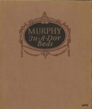
DOUBt6-'DOOR<br />
SINGLE-DOOR,<br />
DOORS* ~ '-O~O~L€ HU6HT<br />
OUTSIDE- eH.tVATIONS<br />
SCALE- it" -'-on
JcaIe for Detail/<br />
!>"={'-0"<br />
DOUBLE" DOORS<br />
SINGLE-DOOR<br />
DOORS - 6'.d- OR-LESS-IN-HEIGHT<br />
OUTSIDE- - ELEVATION<br />
SCALE-. I/&' = 1'-$<br />
DOUBLE DGDRS SINGLE-DODR<br />
DOORS - OVER - ~~o'!~-uP-To-~~!~'HIGH<br />
OUTSIDE<br />
SCALE- 78 = 1-0"<br />
NOTE<br />
ELEVATIONS<br />
F1AIHING.f fOlt OUTRIDE JLIDE DOOHf<br />
NOT FUltUl-fHED BY LUPTON<br />
LEFT HAND 1 RIGHT HAND 1<br />
J I I<br />
KEY FOR, HAND OF DOORS
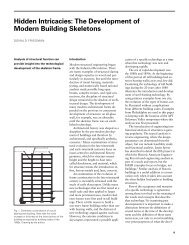
COMMERCIAL DOORS<br />
<strong>Lupton</strong> Commercial Doors are designed for use as exterior<br />
or interior doors for garages, manufacturing plants, etc.,<br />
where inexpensive steel doors are desirable. Lighter in<br />
construction than <strong>Industrial</strong> Doors, they are, within their<br />
size limits, a practical and economical product.<br />
Sizes and Construction<br />
Doors are made only in stock sizes shown below. Stiles<br />
and rails are made of 18 gauge sleel, mitered and welded<br />
at comers of door and the welds ground flush. The lower<br />
part d door has a 16 gauge steel panel and the upper part<br />
is made to receive glass. Frames are furnished for swing<br />
doors only and only when specified. They are made of steel<br />
plate. Flat steel anchors are provided at jambs and an<br />
expansion bolt at head.<br />
Hardware<br />
All necessary hardware is included with doors except<br />
Hook Back No. 101 which must be specified if required.<br />
In ordering swing doors specify whether Mortise Lock or<br />
Lever Latch is desired,<br />
Erection (See page 3).<br />
Door frames must be set plumb and square, securely<br />
anchored to building. Tracks for slide doors must be level<br />
and anchored securely.<br />
Swing doors are drilled in shop for hin es and when Lock<br />
No. 97 is ordered doors are mortised and drilled to receive<br />
it. All other drillin must be done in field.<br />
Single doors with frames are shi ed assembled in frames.<br />
Double doors are shipped separately from frames.<br />
Glazing and Painting (See page 3)<br />
See table below for glass sizes. Orders for doors do not<br />
include glass, but steel glazing stops are furnished, shipped<br />
attached. Always use steel window putty and glaze after<br />
doors are erected.<br />
Doors are given one shop coat of gray paint, oven dried.<br />
Ordering<br />
When ordering give the following information:<br />
1. Symbol numbers of doors required (D-1, D-2, etc.).<br />
2. Quantity of each type required.<br />
3. whether doors are to swing of slide and whether<br />
right or lei! hand. (Se& "Key for Hand of Doors" on next<br />
pags.) If Swing Doors are ordered state also:-<br />
a. Type of lock desired (No. 97 or No. 98).<br />
b. If frame8 are required, give Door Frame Marks (see<br />
table below).<br />
c. Whether or not Hook Backs are required.<br />
Slide door Trolleys and Tracks<br />
are shown on Plaie NÂ 531 a<br />
MORTISE LOCK.<br />
No. 97 - for<br />
bin@ doors<br />
fcf/y LATC H and<br />
padlock bracket<br />
No. 98<br />
lor hirpd ctoor~<br />
HOOK BACK<br />
No. 101- For<br />
cmtcr of track. {or -<br />
double dide doow-<br />
4Lcff)<br />
DOORJTOP<br />
NO. I08 for<br />
sbdt a'oers<br />
!igM/ÑÃ<br />
Hin8 Na99<br />
J T A M D A R . D o i l Z & S o<br />
ACTpti-sSrucod<br />
oraviovie floors<br />
m<br />
ford forcomerrte<br />
HASP and JTAPLE<br />
No Ill - For dlde doon<br />
-(few<br />
DOOR GUI DE<br />
No. 106-A /or<br />
slide doors'-<br />
D-l 0-2 0-3 D -4 D.3 D -21 022 D.23 D.24 D- 25<br />
JINGLE DOORJ DOU6LE DOORJ /<br />
1 SWING DOORS<br />
SWING OR SLIDE SLIDE DOORS I<br />
OBtalog No<br />
of Anneal<br />
No. of<br />
Light*<br />
10' 0'<br />
DF-3<br />
DF"4<br />
TO' D-21 DF-21 2392<br />
7' 0' D-22 DF-22 2392
HANGAR DOORS<br />
These doors are built by skilled workmen to satisfy the<br />
exacting requirements of the airplane industry. Made<br />
in two types, Straight Slide Type and Around-the-<br />
Corner Type.<br />
Sizes of Openings<br />
Standard opening heights range from 12 to 30 ft. Larger doors<br />
of the same dasign can be furnished when required.<br />
Width 01 a door unit is approximately 10 ft. Hinged end units<br />
for use with around-the-corner doors, are approximately 4 or 5 It.<br />
as required. It is desirable to make the total width of opening<br />
some multiple of 10 ft. (40, 50, etc.)<br />
Construction<br />
Doors are made of steel tubing (shown in detail) or structural<br />
steel channel as specified. All joints between frame members are<br />
solidly weldad and the exposed part of the weid ground flush.<br />
Pilot doors are provided where required. They are made of<br />
1% x 2%-in. steal tubing and are equipped with cylinder locks.<br />
Glazing panels are glazed inside with putty. Glass is held by<br />
steel wire glazing clips.<br />
Hardware<br />
Weight of door is carried on two bottom rollers running on<br />
16-lb. A.S.C.E. rails. Doors are guided at top by two double rollers<br />
bearing on a structural steel angle. Bottom rollers have Timken<br />
bearings and Alemite fittings for lubrication. A ball thrust bearing<br />
is used to pivot rollers for around-the-corner doors.<br />
Slide doors are equipped with a wheel lock for locking door at<br />
any desired position. Cremone bolts are furnished for locking<br />
hinged end doors. Bumpers are furnished at ends of tracks.<br />
Travel of doors is limited by stops at lop of door.
LED STEEL<br />
lled Steel Skylight is especially adapted to<br />
of unusual severity such as vibration, wide<br />
temperatures, and inaccessibility for<br />
patented construction eliminates breakage of<br />
due to expansion and contraction, and to vibraon.<br />
Leakage, due to drying of putty, rapid deteriorasion<br />
and collection of dust by condensalion<br />
gutters are all eliminated by the <strong>Lupton</strong> Skylight.<br />
The glass is supported between flexible strands of<br />
specially saturated fibre. This permits free expansion<br />
and contraction, without leakage, since no putty is<br />
SKYLIGHT<br />
Erection of Luoton Skyliqht involves no cutting<br />
and fitting. All memberi are cut to exact size, the<br />
bars and caps are offset at the factory, and all parts<br />
are shipped ready for assembling. Erection can be<br />
done by ordinary mechanics.<br />
Specifications<br />
Work Included<br />
vish and install where shown on drawings <strong>Lupton</strong> Rolled<br />
manufactured by Michael Flynn Manulacturing<br />
y, Philadelphia, Pa.<br />
I<br />
Note:-(a)<br />
Materialta<br />
liqht Bar shall be a specially rolled solid, one-pitece,<br />
steel section.<br />
3. The cap shall be specially formed of 16 oz. cold rolled<br />
Lfçf)~<br />
Studs shall be 04 malleable iron passing through the cap<br />
brass dome nuts.<br />
4. Curb Aprons of 16 oz. cold rolled copper shall be furnished.<br />
Note-Caps or curb aprons or both will be furnished i 24<br />
vanized steel at a corresponding price when specif id.<br />
upte:-(a)<br />
lmctor.<br />
Anchors are not set in the masonry by the skylight<br />
Construction<br />
6. Skvliaht bars and Cms shall be cut to the wrooer lenaths<br />
Erection (See page 3)<br />
7. Luplon Rolled Steel Skylight shall be erected in prepared<br />
openings by the skylight contractor (unless otherwise specified)<br />
in accordance with the standard details for this product.<br />
Include in the masonry specification that openings<br />
for skylights be prepared according to the standard details for<br />
<strong>Lupton</strong> Rolled Steel Skylight. Anchor clips must be imbedded in<br />
the masonry as shown in details.<br />
(b) Include in the structural steel specification that all punching<br />
for clips, etc., required for the installation of <strong>Lupton</strong> Rolled Steel<br />
Skylight must be done by the Steel contractor.<br />
8. The glass shall be supported longitudinally on saturated<br />
cords of specially treated fibre resting in the flanges of the skylight<br />
bars.<br />
Where two sheets of glass overlap, they shall be separated by<br />
saturated cords. The caps shall be separated from the glass by '<br />
saturated cord and held in place by the studs and cap nuts.<br />
9. Curbs, hips and ridges shall be calked with roofing cement<br />
and flashin shall be applied at hips and ridges as indicated on<br />
the details for <strong>Lupton</strong> Rolled Steel Skylight.<br />
Painting<br />
10. All skylight bars shall receive one coat of red lead primer<br />
on the outside and one coat of asphaltum on the inside before<br />
shipment.<br />
Glass (See page 3)<br />
Note:-Specify the following under the proper heading in<br />
specifications of other trades.<br />
(a) }
DOU~LE.PITCH-/KYLIGHT<br />
PLAN -AND -/ECTION