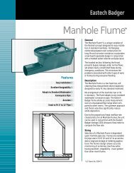
HS3 Sensor IOM - Eastech Flow Controls
HS3 Sensor IOM - Eastech Flow Controls
HS3 Sensor IOM - Eastech Flow Controls

Create successful ePaper yourself
Turn your PDF publications into a flip-book with our unique Google optimized e-Paper software.
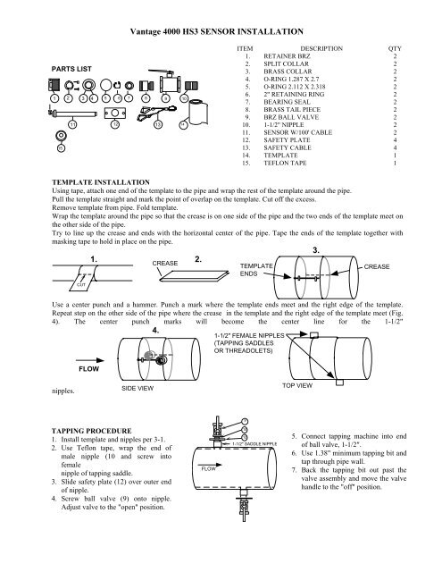
Vantage 4000 <strong>HS3</strong> SENSOR INSTALLATION<br />
PARTS LIST<br />
2 1 3 4 5 6 7 8 9 10<br />
15<br />
11 12 13 14<br />
ITEM DESCRIPTION QTY<br />
1. RETAINER BRZ 2<br />
2. SPLIT COLLAR 2<br />
3. BRASS COLLAR 2<br />
4. O-RING 1.287 X 2.7 2<br />
5. O-RING 2.112 X 2.318 2<br />
6. 2" RETAINING RING 2<br />
7. BEARING SEAL 2<br />
8. BRASS TAIL PIECE 2<br />
9. BRZ BALL VALVE 2<br />
10. 1-1/2" NIPPLE 2<br />
11. SENSOR W/100' CABLE 2<br />
12. SAFETY PLATE 4<br />
13. SAFETY CABLE 4<br />
14. TEMPLATE 1<br />
15. TEFLON TAPE 1<br />
TEMPLATE INSTALLATION<br />
Using tape, attach one end of the template to the pipe and wrap the rest of the template around the pipe.<br />
Pull the template straight and mark the point of overlap on the template. Cut off the excess.<br />
Remove template from pipe. Fold template.<br />
Wrap the template around the pipe so that the crease is on one side of the pipe and the two ends of the template meet on<br />
the other side of the pipe.<br />
Try to line up the crease and ends with the horizontal center of the pipe. Tape the ends of the template together with<br />
masking tape to hold in place on the pipe.<br />
3.<br />
CUT<br />
1.<br />
CREASE<br />
2.<br />
TEMPLATE<br />
ENDS<br />
CREASE<br />
Use a center punch and a hammer. Punch a mark where the template ends meet and the right edge of the template.<br />
Repeat step on the other side of the pipe where the crease in the template and the right edge of the template meet (Fig.<br />
4). The center punch marks will become the center line for the 1-1/2"<br />
FLOW<br />
4.<br />
1-1/2" FEMALE NIPPLES<br />
(TAPPING SADDLES<br />
OR THREADOLETS)<br />
nipples.<br />
SIDE VIEW<br />
TOP VIEW<br />
9<br />
TAPPING PROCEDURE<br />
1. Install template and nipples per 3-1.<br />
2. Use Teflon tape, wrap the end of<br />
male nipple (10 and screw into<br />
female<br />
nipple of tapping saddle.<br />
3. Slide safety plate (12) over outer end<br />
of nipple.<br />
4. Screw ball valve (9) onto nipple.<br />
Adjust valve to the "open" position.<br />
FLOW<br />
10<br />
12<br />
1-1/2" SADDLE NIPPLE<br />
5. Connect tapping machine into end<br />
of ball valve, 1-1/2".<br />
6. Use 1.38" minimum tapping bit and<br />
tap through pipe wall.<br />
7. Back the tapping bit out past the<br />
valve assembly and move the valve<br />
handle to the "off" position.
PREPARATION TO INSTALL SENSORS:<br />
Vantage 4000 <strong>HS3</strong> SENSOR INSTALLATION<br />
FIG. 1 FIG. 2<br />
SEE NOTE 1 PG. 3-3<br />
5 6 7<br />
8<br />
15<br />
NOTE SCRIBE<br />
MARK<br />
TAIL PIECE ASSEMBLY<br />
(ASSEMBLED AT FACTORY)<br />
11 12 1 2 3 4<br />
SENSOR & COLLAR ASSEMBLY<br />
11 12 1 2 3 4 5 6 7 8 9 12 10<br />
FIG. 3<br />
8.15"<br />
"S"<br />
"S"= Length of saddle or threadolet nipple<br />
"T"= Length from i.d. of pipe to outside<br />
edge of item 8<br />
"T" MEASURED BY INSTALLER<br />
"T"+0.82" OR 8.97"+"S"+WALL THICKNESS<br />
NOTE 1:<br />
USE ABOVE FORMULAS TO DETERMINE THE PLACEMENT OF ITEM 2, ONCE COLLAR IS<br />
PLACED AT CORRECT DIMENSION TIGHTEN BOTH SOCKET HEAD SCREWS.<br />
1. Screw tail piece assembly (Fig. 1, 5, 6, 7 and 8) into ball valve (9).<br />
2. Slide 12 and 1 onto sensor (11); use Fig. 2.<br />
3. Position collar (2) onto sensor and use above formula to calculate correct dimension. Please note that the collar<br />
should already be installed by the factory on new orders, the collar dimension will have to be changed only if pipe<br />
dimensions are other than given.<br />
4. Slide brass collar and O-ring assembly (3 & 4) onto end of sensor and butt up against the split collar (2).<br />
NOTE: USE SOAPY WATER, PETROLEUM JELLY OR SOME TYPE OF LUBRICANT TO SLIDE BRASS<br />
COLLAR AND O-RING ONTO SENSOR.<br />
5. Note scribe mark running near the end of the sensor. This scribe mark, when the sensor is installed, should be facing<br />
toward the opposite sensor (Fig. 4).<br />
6. Place tip of sensor through bearing seal (7) and carefully push until the sensor stops at the ball valve. Fasten safety<br />
cable clip (long length) to opposite safety plate.<br />
7. Turn valve handle to the "on" position and insert the sensor until the brass collar (3) seats on the O-ring on the tail<br />
piece (5 & 8).<br />
8. Tighten retainer (1) onto the tail piece (8) using a 1/16" square screw driver shaft in the notch on the end of the<br />
retainer.<br />
9. Fasten short length of safety cable to opposite safety plate.
Vantage 4000 <strong>HS3</strong> SENSOR INSTALLATION<br />
UPSTREAM<br />
SCRIBE<br />
MARK<br />
FLO<br />
NOTE: TIPS OF SENSORS<br />
WILL BE FACING EACH<br />
OTHER<br />
FIG. 4<br />
SCRIBE<br />
MARK<br />
DOWNSTREAM<br />
SYSTEM<br />
DIAGRAM<br />
JUNCTION BOX<br />
(CUSTOMER SUPPLIED)<br />
METALLIC CONDUIT<br />
(CUSTOMER SUPPLIED)<br />
117/230VAC<br />
OR 12VDC<br />
OUTPUTS<br />
FLEX CONDUIT<br />
(CUSTOMER SUPPLIED)