Filter Media - Filtration News
Filter Media - Filtration News
Filter Media - Filtration News

You also want an ePaper? Increase the reach of your titles
YUMPU automatically turns print PDFs into web optimized ePapers that Google loves.
I N T E R N A T I O N A L<br />
FILTRATION<br />
NEWS<br />
January/February 2010<br />
Volume 29 No. 1<br />
www.filtnews.com<br />
Your Global Source<br />
Sparklefilter ®<br />
by SpinTek <br />
Automatic Backpulse<br />
Removes Bacteria<br />
Continuously<br />
Industry Analysis:<br />
<strong>Filtration</strong> & Separation<br />
Industry Will Remain<br />
Vibrant and Grow<br />
<strong>Filter</strong> <strong>Media</strong>:<br />
Selecting a Nonwoven<br />
<strong>Filter</strong> Medium That Is Right<br />
for Your Application
IN THIS ISSUE<br />
January/February 2010, Volume 29, No. 1<br />
Industry | Analysis<br />
<strong>Filtration</strong> & Separation Industry Will Remain Vibrant and Grow 4<br />
Ceramic Fiber | <strong>Filter</strong> <strong>Media</strong><br />
A Breakthrough in “In-Situ” <strong>Filter</strong> Cleaning 8<br />
Cover Story | SpinTek <strong>Filtration</strong><br />
Automatic Backpulse - Safer Water Quality 12<br />
<strong>Filter</strong> <strong>Media</strong> | Nonwoven<br />
Selecting a Nonwoven <strong>Filter</strong> Medium That Is Right<br />
for Your Application 14<br />
Adsorption | Activated Carbons<br />
Removing PCBs From Groundwater Utilizing<br />
Activated Carbon 18<br />
Test Methods | Name Change<br />
GRPD Becomes GAED Sorbent Test Method 22<br />
Crossflow | Membranes<br />
Koch Membrane Systems Introduces New Lees<br />
Treatment in Wineries 24<br />
Waste | Recycling<br />
Turning Waste Oil Into Profit 28<br />
Industry | <strong>News</strong><br />
TIGG Corporation Meets Methyl Bromide<br />
Recapture Standards Established by USA-QPS 30<br />
Racor Provides Replacement Elements for<br />
Blue Bird’s Cooper Air Cleaner 30<br />
Industrial Water <strong>Filter</strong>s 31<br />
Sealant’s New See-Flo 1100 Improves Meter-Mix Dispense 33<br />
Industry | Events<br />
Emphasis on Liquids and Separations at AFSS Conference 32<br />
I N T E R N A T I O N A L<br />
FILTRATION<br />
January/February 2010<br />
Volume 29 No. 1<br />
www.filtnews.com<br />
NEWS<br />
Your Global Source<br />
Sparklefilter ®<br />
by SpinTek <br />
Automatic Backpulse<br />
Removes Bacteria<br />
Continuously<br />
Industry Analysis:<br />
<strong>Filtration</strong> & Separation<br />
Industry Will Remain<br />
Vibrant and Grow<br />
<strong>Filter</strong> <strong>Media</strong>:<br />
Selecting a Nonwoven<br />
<strong>Filter</strong> Medium That Is Right<br />
for Your Application<br />
Cover courtesy of<br />
SpinTek<br />
Design by Ken Norberg<br />
Published by<br />
EAGLE PUBLICATIONS, INC.<br />
In Association with<br />
INTERNATIONAL<br />
MEDIA GROUP, INC.<br />
6000 Fairview Road, Suite 1200<br />
Charlotte, NC 28210 USA<br />
Carol and Arthur Brown, Founders<br />
Klaas DeWaal, Publisher and CEO<br />
Antoinette DeWaal, Associate Publisher<br />
and Vice President<br />
Ken Norberg, Editor in Chief<br />
Advertising Sales Representatives<br />
Gail Dawson<br />
Joan Oakley<br />
Debra Klupacs<br />
Administration Department<br />
Barbara Ragsdale<br />
Circulation Department<br />
Cherri Jonte<br />
Publication Data<br />
Printed by: Allegra Print & Imaging,<br />
Wixom, MI 48393.<br />
<strong>Filtration</strong> <strong>News</strong> (ISSN:1078-4136) is<br />
published bi-monthly by<br />
Eagle Publications, Inc.<br />
Printed in U.S.A., Copyright 2010.<br />
This publication has a controlled<br />
circulation - controlled by the staff of <strong>Filtration</strong><br />
<strong>News</strong>; mailed bi-monthly by Bulk Mail.<br />
<strong>Filtration</strong> <strong>News</strong> is not responsible for<br />
statements published in this magazine.<br />
Advertisers, agencies and contributing writers<br />
assume liability for all content of all submitted<br />
material printed and assume responsibility for<br />
any claims arising there-from made against<br />
publisher.<br />
Mailing Address for advertising, news<br />
releases and address changes:<br />
<strong>Filtration</strong> <strong>News</strong><br />
42400 Grand River / Suite 103<br />
Novi, Michigan 48375-2572<br />
Phone: (248) 347 - 3486<br />
Fax: (248) 239 - 0670<br />
www.filtnews.com<br />
Application to mail at periodicals postage<br />
prices is pending at Novi, Michigan and<br />
additional mailing offices.<br />
POSTMASTER: Send address changes to<br />
<strong>Filtration</strong> <strong>News</strong><br />
42400 Grand River / Suite 103, Novi<br />
Michigan 48375-2572, U.S.A.<br />
2 • February 2010 • www.filtnews.com
Editorial Advisory Board<br />
Editorial Board Chairman<br />
Edward C. Gregor, Chairman<br />
E.C. Gregor & Assoc. LLC<br />
Tel: 1 704 442 1940<br />
Fax: 1 704 442 1778<br />
ecg@egregor.com<br />
M&A, <strong>Filtration</strong> <strong>Media</strong><br />
Haluk Alper, President<br />
MyCelx Technologies Corp.<br />
Tel: 770.534.3118<br />
Fax: 770.534.3117<br />
alper@mycelx.com<br />
Oil Removal – Water and Air<br />
Peter S. Cartwright, PE<br />
Cartwright Consulting Co.<br />
cartwrightconsul@cs.com<br />
Membranes, RO,<br />
Ultrafiltration<br />
Wu Chen<br />
The Dow Chemical Company<br />
Tel: 1 979 238 9943<br />
Fax: 1 979 238 0651<br />
Process <strong>Filtration</strong> (liquid/gas)<br />
Equipment and <strong>Media</strong><br />
Peter R. Johnston, PE<br />
Tel/Fax: 1 919 942 9092<br />
ddandp3@aol.com<br />
Test procedures<br />
Jim Joseph<br />
Joseph Marketing<br />
Tel/Fax: 1 757 565 1549<br />
josephmarketing@verizon.net<br />
Coolant <strong>Filtration</strong><br />
Gerard J. Lynch, PE<br />
Sigma Design Co., LLC<br />
Tel: 1 973 912 7922<br />
Fax: 1 973 912 5244<br />
gjlynch@sigmadesign.net<br />
<strong>Filtration</strong> Machinery &<br />
Product Design<br />
Dr. Ernest Mayer<br />
DuPont Co.<br />
Tel: 1 302 368 0021<br />
Fax: 1 302 368 1474<br />
ernest.mayer@usa.dupont.com<br />
General Solid/Liquid Separations<br />
in All Areas<br />
Robert W. Mcilvaine<br />
Tel: 1 847 272 0010<br />
Fax: 1 847 272 9673<br />
mcilvaine@<br />
mcilvainecompany.com<br />
www.mcilvainecompany.com<br />
Mkt. Research & Tech. Analysis<br />
Henry Nowicki, Ph.D. MBA<br />
Tel: 1 724 457 6576<br />
Fax: 1 724 457 1214<br />
Henry@pacslabs.com<br />
www.pacslabs.com<br />
Absorbent Testing<br />
and Training<br />
Brandon Ost, CEO<br />
<strong>Filtration</strong> Group<br />
High Purity Prod. Div.<br />
Tel: 1 630 723 2900<br />
bost@filtrationgroup.com<br />
Air <strong>Filter</strong>s, Pharmaceutical<br />
and Micro-Electronic<br />
Dr. Graham Rideal<br />
Whitehouse Scientific Ltd.<br />
Tel: +44 1244 33 26 26<br />
Fax: +44 1244 33 50 98<br />
rideal@<br />
whitehousescientific.com<br />
<strong>Filter</strong> and <strong>Media</strong> Validation<br />
Andy Rosol<br />
Global <strong>Filtration</strong> Products Mgr.<br />
FLSmidth Minerals<br />
andy.rosol@flsmidth.com<br />
Tel: 1 800 826 6461/1 801 526 2005<br />
Precoat/Bodyfeed <strong>Filter</strong> Aids<br />
Gregg Poppe<br />
The Dow Chemical Company<br />
Tel: 1 952 897 4317<br />
Fax: 1 942 835 4996<br />
poppeg@dow.com<br />
Industrial Water, Power,<br />
and Membrane Technology<br />
Tony Shucosky<br />
Pall Microelectronics<br />
Tel: 1 410 252-0800<br />
Fax: 1 410 252-6027<br />
tony_shucosky@pall.com<br />
Cartridges, <strong>Filter</strong> <strong>Media</strong>,<br />
Membranes<br />
Scott P. Yaeger<br />
<strong>Filtration</strong> and Separation<br />
Technology LLC<br />
Tel/Fax: 219-324-3786<br />
Mobile: 805-377-5082<br />
spyaeger@msn.com<br />
Membranes, New Techn.<br />
Wells Shoemaker<br />
Advisory Board<br />
Member Emeritus<br />
Dr. Bob Baumann<br />
Advisory Board<br />
Member Emeritus<br />
www.filtnews.com • February 2010 • 3
Industry | Analysis<br />
<strong>Filtration</strong> & Separation Industry<br />
Will Remain Vibrant and Grow<br />
By Wu Chen, Ph.D., Dow Chemical, Freeport, Texas, U.S.A.<br />
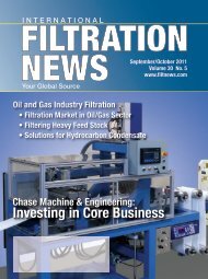
F<br />
iltration technology is used in<br />
all industries and households<br />
and is an important part of<br />
human life. The filtration and separation<br />
industry provides services and devices<br />
to meet these filtration needs.<br />
Since it covers such a wide applications<br />
spectrum, it is natural that this industry<br />
is very diversified, segmented and not<br />
well understood. Most of the work and<br />
industry analyses are focusing on certain<br />
market segments or technology. It<br />
is very difficult and seldom attempted<br />
to have a sensible analysis of the whole<br />
filtration and separation industry.<br />
THE BIGGER PICTURE<br />
Very often when people talk about<br />
filtration, they have filter media in<br />
mind. Although this thought is true in<br />
many cases, a lot can be missed. <strong>Filter</strong><br />
media is crucial in a filtration process<br />
but there are also many separations carried<br />
without a filter medium. Even in<br />
true filtration processes, often the filter<br />
medium is only part of the whole unit.<br />
There are more components than just<br />
the filter media to make the filter work.<br />
Figure 1. Fluid/Particle Separation Technology<br />
When discussing the filtration industry,<br />
one needs to be aware of what is really<br />
in the so-called filtration world, and<br />
this needs to be discussed from three<br />
different aspects; technology, market<br />
segments and value chain.<br />
EVALUATION OF INDUSTRY<br />
It is customarily to use the term filtration<br />
to refer to the process of separating<br />
particles from a fluid stream. It<br />
is further divided into two distinct<br />
areas, air filtration and liquid filtration.<br />
Since a filter medium is not always<br />
used in separating particles from a fluid<br />
stream, the term of filtration is really<br />
limited to separation processes involving<br />
the use of separation septa. A better<br />
term, fluid/particle separation, should<br />
be used. Within fluid/particle separations,<br />
there are solid/liquid separations<br />
and solid/gas separations and each of<br />
them includes different technologies 1 ,<br />
2<br />
(Figure 1).<br />
Solid/Gas Separation<br />
Solid/gas separation can be further<br />
divided into two major areas – filtration<br />
4 • February 2010 • www.filtnews.com<br />
and separation depending on whether a<br />
filter medium is used. As filtration is the<br />
dominant mechanism in solid/gas separation<br />
and most applications involve air,<br />
the term “air filtration” is often used to<br />
refer to this whole industry.<br />
There are two key filtration mechanisms,<br />
direct sieving and indirect interceptions.<br />
In direct sieving, the particles<br />
are larger than the openings of the filter<br />
medium and get filtered out. The more<br />
commonly encountered filtration<br />
mechanism in gas filtration is indirect<br />
interception where the particles are collected<br />
by the filter media by inertial impaction,<br />
diffusion (Brownian motion),<br />
interception, and electrostatic effects.<br />
In addition to filtration, there are also<br />
separation methods without filter<br />
media. These methods utilize inertia,<br />
electrostatic or centrifugal forces to<br />
achieve solid/gas separation.<br />
Solid/Liquid Separation<br />
Solid/liquid separation technology<br />
can also be divided into filtration and<br />
separation. Depending on the filtration<br />
mechanism, there are four sub-categories<br />
in liquid filtration.<br />
The simplest filtration<br />
mechanism is<br />
straining where particles<br />
are caught on the<br />
medium by direct sieving.<br />
Particles larger<br />
than the medium<br />
openings are filtered<br />
out. The second mechanism<br />
is cake filtration<br />
where the number of<br />
particles is high<br />
enough to form a particle<br />
bed called the filter<br />
cake. This cake<br />
becomes the primary
filter septum and the original filter<br />
medium is not as important in the particle<br />
capture. Sometimes the filter media<br />
are thick so the particles are caught inside<br />
the filter media. This type of filtration<br />
is called depth filtration. Very fine<br />
particles tend to form a dense cake and<br />
retard the filtration rate, in these cases<br />
cross flow filtrations are commonly<br />
used to keep the particles from forming<br />
a cake. This technique is used by most<br />
membrane filters since they are used to<br />
separate very fine particles.<br />
Beside filtration, solid/liquid separation<br />
can also be accomplished by gravitational<br />
or centrifugal forces where the<br />
particles are separated due to their density<br />
differences from the liquid phase.<br />
Different equipment and design considerations<br />
are used for these two mechanisms.<br />
Flotation, also utilizes<br />
gravitational force but the particles are<br />
made lighter than the liquid phase so<br />
they float to the top and are separated.<br />
There are other field-forces like magnetic<br />
and electrostatic forces used for<br />
separating particles from liquid streams.<br />
Unlike solid/gas separtion, the mechanisms<br />
of filtration and separation are<br />
equally used and none of the applications<br />
dominate solid/liquid separation.<br />
Therefore, the commonly used term of<br />
“liquid filtration” is not a good representative<br />
term for solid/liquid separation.<br />
The above brief discussion provides<br />
high lever overview of technologies<br />
used in the filtration and separation industry<br />
today. It can be seen that this industry<br />
covers a broad technology<br />
spectrum. Therefore, it is very difficult<br />
for any participant to engage in more<br />
than one technology area. Almost all of<br />
the companies in this industry focus<br />
on one or part of one technology area.<br />
In North America, very few companies<br />
are able to participate in multiple technology<br />
areas. One example is Pall,<br />
which is strong in straining type of liquid<br />
filtration technology but also participate<br />
in businesses involving cake<br />
filtration, cross flow filtration and gas<br />
filtration technologies.<br />
The trend will continue as large<br />
companies like Pall continue to expand<br />
their technology envelope. There will<br />
also be smaller companies who focus<br />
on part of a technology area and excel<br />
in that specific market. An example is<br />
the Oberlin <strong>Filter</strong> Company who focuses<br />
on one type of cake filters.<br />
EVALUATION BY MARKET SEGMENTS<br />
With broad application coverages in<br />
filtration and separation, it is not surprising<br />
that this industry is highly segmented.<br />
These market segments are<br />
most often categorized by applications.<br />
The detailed name and number of segments<br />
vary from analyst to analyst. The<br />
major commonly used segments will be<br />
briefly reviewed.<br />
Solid/Gas Separation (Air <strong>Filtration</strong>)<br />
This area involves removal of particulates<br />
from a gas stream. As air filtration<br />
has the most number of<br />
applications and highest volumes of<br />
sales, the term air filtration is commonly<br />
used by this industry. Its primary<br />
segments include:<br />
• HVAC (Heating, Ventilating and<br />
Air Conditioning)<br />
• HEPA/ULPA (High Efficiency<br />
Particulate Air/Ultra Low<br />
Penetration Air)<br />
• Power generation<br />
• Transportation (filtration for<br />
www.filtnews.com • February 2010 • 5
Industry | Analysis<br />
engine intake, exhaust and cabin air)<br />
• Vacuum cleaners<br />
• Medical<br />
• Military<br />
• Industrial dust control<br />
• Others<br />
The applications above are predominantly<br />
accomplished through filter<br />
media. Therefore, filter media plays the<br />
key role in the solid/gas separation<br />
arena. Although each segment has its<br />
own opportunity and development<br />
trend, the emphasis on filter media is<br />
universal among all segments. The common<br />
needs are to increase efficiency in<br />
particle removal, reduce pressure drop,<br />
and in the meantime, lower the cost.<br />
This trend has been in the past and will<br />
continue in the future.<br />
The use of membrane media is a<br />
major approach toward high efficiency<br />
filters. New material (like PTFE) gradually<br />
finds its place in the media market<br />
with its better performance in pore size<br />
control and chemical compatibility. Due<br />
to the high cost of membranes, meltblown<br />
technology is continually being<br />
improved to provide low-cost high efficiency<br />
media. The use of nano fibers are<br />
now on the rise and this may provide a<br />
proper middle point between meltblown<br />
and membrane media in terms of cost<br />
and filtration efficiency.<br />
Solid/Liquid Separation<br />
In solid/liquid separation applications,<br />
filtration is not the dominant<br />
mechanism. The utilization of filtration<br />
or separation (non-filtration) is about<br />
the same. The major industrial segments<br />
include:<br />
• Water treatment<br />
• Petro-chemicals<br />
• Food and beverage<br />
• Biopharmaceutical<br />
• Fuel<br />
• Electronics<br />
• Medical<br />
• Marine<br />
• Military<br />
• Transportation<br />
• Mining & Minerals<br />
• Others<br />
Figure 2. Value chain in<br />
the filtration and<br />
separation industry<br />
Similar to air filtration, the major development<br />
area in the liquid filtration<br />
arena is the media. The opportunities<br />
and trends are very similar to those in<br />
air filtration. One of the key differences<br />
between solid/liquid separation and<br />
solid/gas separation is that equipment<br />
and mechanical design are much more<br />
emphasized in solid/liquid separation<br />
arena. For example, in the biopharmaceutical<br />
and food & beverage industries,<br />
CIP (clean-in-place) is a must and<br />
effort is spent in improving that capability.<br />
This trend will continue. In membrane<br />
filtration, not only the membrane<br />
itself is the subject of improvement, but<br />
the module design to increase surface<br />
area, the vessel design to improve the<br />
controllability of crossflow and transmembrane<br />
pressure, and the seal design<br />
for different chemicals all present challenges<br />
and opportunities.<br />
Evaluation by Value Chain<br />
The size of the filtration and separation<br />
market is at least $20 - $30 billion 3 ,<br />
4<br />
depending on how one analyzes the<br />
market and could be much larger if a<br />
broader value chain scope is considered.<br />
The fact that many market segments<br />
exist causes some discrepancies in the<br />
market analyses. The major confusion<br />
is probably coming from how one defines<br />
this industry’s boundary. Figure 2<br />
shows the value chain involved in the<br />
filtration and separation industry. A sensible<br />
market evaluation needs to have a<br />
clear definition of the scope included in<br />
the analyses. Many times, people only<br />
6 • February 2010 • www.filtnews.com<br />
consider media producers and filter fabricators<br />
as the “filtration industry”,<br />
which is sufficient if interests are only<br />
in the fiber or media business. For a better<br />
understanding of this whole industry,<br />
it is worth while to look at the value<br />
chain in a bigger picture.<br />
The value chain starts with material<br />
supplies. This alone is a very large industry,<br />
which includes plastics<br />
(polypropylene, polyester, nylon, PTFE,<br />
etc.), metals (steel, stainless steel or<br />
other metals), adhesives (epoxy,<br />
polyurethane, etc.), and more. The filtration<br />
industry has not been putting a<br />
lot of effort into the improvement in<br />
this area since it may be quite involved<br />
to introduce a new material to the manufacturing<br />
process or market. It can also<br />
be due to a lack of awareness of the advances<br />
and opportunities in raw materials.<br />
With today’s progress in the<br />
chemical industry, there are great opportunities<br />
in plastic materials alone.<br />
There are technologies that allow plastics<br />
to have improved properties like<br />
higher temperature resistance, better<br />
chemical resistance, higher tensile<br />
strength, better removal efficiency for<br />
special substances like fine particles or<br />
allergens and lower melt viscosity to<br />
allow for order of magnitude faster<br />
speed in the media manufacturing.<br />
The next step in the value chain is<br />
the media producers, filter component<br />
producers or equipment parts producers.<br />
These are all essential parts of a filter<br />
or a separator. In the filtration and<br />
separation industry, the attention has
een in the media production as it is<br />
considered the core of the filtration. The<br />
industry for filter media itself has many<br />
segments and it takes a book to discuss<br />
them individually. Besides the general<br />
trend of developing higher efficiency,<br />
lower pressure drop and lower cost<br />
media, custom tailored media for specific<br />
applications to catch a niche market<br />
is also on the rise. One example is<br />
multifunctional media which can remove<br />
volatile organic compounds and<br />
odor as well as particulates. This kind<br />
of medium is especially useful in the automotive<br />
cabin air filter segment.<br />
<strong>Filter</strong> fabricators and equipment fabricators<br />
take the filter media and make<br />
the filter. While filters with different<br />
configurations can be made from the<br />
same media, the drive is to maximize the<br />
filtration area within the space constrain<br />
but maintain filtration efficiencies and<br />
operation capability. Frequently used approaches<br />
include the use of pleated<br />
media, multi-layer media, graded depth<br />
media structure and other innovative<br />
designs. For improving filtration efficiency,<br />
finer fibers or surface treatments<br />
are the general direction. For equipment<br />
fabricators (either for filters or separators),<br />
improvement in equipment design<br />
is focusing on material handling (like<br />
cake discharge, leak-by prevention) as<br />
well as better separation efficiency<br />
(higher electrostatic charge, longer lived<br />
electrostatic charge, higher centrifugal<br />
force, lower turbulences, etc.).<br />
Another important driver for more<br />
efficient filter media is government<br />
regulations. In the U.S., regulation has<br />
tightened the emission specifications<br />
from PM10 to PM2.5 (Particulate Matter<br />
smaller than 10 or 2.5 microns).<br />
This has impacted the emission filter<br />
design for power generation and created<br />
challenges and opportunities for<br />
filter bag suppliers.<br />
System integrators put ancillaries<br />
(pump, pipe, valves, controllers, etc.)<br />
together so the filter can function. In<br />
many applications, the “standard” system<br />
is provided. With the increasing<br />
demand in the market, especially in<br />
the solid/liquid separation market,<br />
suppliers need to be able to respond<br />
quickly and design systems for new or<br />
specific applications.<br />
Distributors play an important role<br />
between the end user and suppliers.<br />
Traditionally, they just distribute or sell<br />
but the trend in the past decade and for<br />
sure in the future is that the distributors<br />
will have a larger role as the field<br />
support for the filter suppliers and<br />
VOC (voice of customers) for the customers.<br />
They can even influence or<br />
control the trend of future development.<br />
Good examples are Walmart and<br />
Home Depot, with their high sales volumes;<br />
they set the standard and are influential<br />
in the Test Method definition.<br />
The end users are the actual consumers<br />
of the filter or separators.<br />
There are industrial users who normally<br />
place orders in large dollar<br />
amounts. There are also household<br />
users. Although the individual purchased<br />
quantity is small, the total<br />
number of domestic users outweighs<br />
any industrial users.<br />
None of the filters last forever and<br />
sooner or later they need to be replaced.<br />
The disposal of spent filter or<br />
related materials was seldom considered<br />
in the value chain since it is mixed<br />
with other waste/trash. With the growing<br />
awareness of environmental protection<br />
globally, there is a need to<br />
address the waste from spent filters or<br />
separators. This is already true in the<br />
industrial filtration processes. One of<br />
the major drives in the filtration industry<br />
today is to design longer life filters<br />
but there will still be plenty of<br />
waste to be disposed. Businesses relating<br />
to spent filter disposal will have<br />
opportunities in the future.<br />
ON THE HORIZON<br />
Some examples of challenges and<br />
opportunities in this industry can also<br />
be seen from the American <strong>Filtration</strong> &<br />
Separation Society Conference. This<br />
conference is devoted to the infrastructure<br />
and sustainability in the filtration’s<br />
growth markets. Key topics that have<br />
been discusses are:<br />
• Water - our lifeline and nature’s<br />
greatest resource<br />
• Water Reuse - saving precious<br />
resources<br />
• Ultrapure Air - commercial and<br />
industrial challenges<br />
• Health and the Environment<br />
www.filtnews.com • February 2010 • 7<br />
• Reusable and Extended Life <strong>Filter</strong>s<br />
– eliminating/reducing waste<br />
• Challenges in Transportation<br />
• Energy and Power Generation<br />
• <strong>Filtration</strong> in Defense and<br />
International Security Issues<br />
These subjects may not be all inclusive<br />
but definitely provide a good view<br />
of the industrial trend in people’s mind.<br />
CONCLUSION<br />
There is no doubt the filtration and<br />
separation industry will remain a vibrant<br />
and growing4 industry. The challenges<br />
remain in its highly segmented markets<br />
and the difficulties in getting complete<br />
appreciation of its opportunities. An understanding<br />
from a bigger picture view<br />
of the whole industry will be a good start<br />
FN<br />
to get ahead in this industry.<br />
References<br />
1. American <strong>Filtration</strong> & Separation Society,<br />
“<strong>Filtration</strong> Basic Course - Basic Solid/Liquid<br />
Separation”, course note, Ann Arbor, MI (2007).<br />
2. American <strong>Filtration</strong> & Separation Society,<br />
“<strong>Filtration</strong> Basic Course - Basic Air <strong>Filtration</strong>”,<br />
course note, Ann Arbor, MI (2007).<br />
3. Rideal, G., “<strong>Filtration</strong>: the Marketplace,”<br />
<strong>Filtration</strong> & Separation, Sept. (2005)<br />
4. Sutherland, K., “Defining the <strong>Filtration</strong><br />
Market,” <strong>Filtration</strong> & Separation, Mar. (2005)
Ceramic Fiber | <strong>Filter</strong> <strong>Media</strong><br />
A Breakthrough in “In-Situ” <strong>Filter</strong> Cleaning<br />
By Dick Nixdorf, President & CEO, Industrial Ceramic Solutions, LLC<br />
Figure 1. All ceramic fiber<br />
media at 300X magnification<br />
8 • February 2010 • www.filtnews.com<br />
T<br />
oday’s global economy has<br />
placed industry in developed<br />
countries at a competitive<br />
disadvantage with developing countries<br />
in the areas of labor costs and<br />
environmental regulations. The answer<br />
to maintaining market share and<br />
reasonable profit margins is reducing<br />
manufacturing costs and minimizing<br />
environmental compliance expense.<br />
Industrial process efficiency improvements<br />
usually require higher operating<br />
temperatures. Lower emission<br />
control expenses require a need to replace<br />
outdated pollution control systems<br />
with innovative filtration technologies.<br />
Temperature dependent industrial<br />
manufacturing requires<br />
increasing the process exhaust temperature<br />
beyond the limits of the current<br />
cellulosic or polymeric filtration<br />
equipment. The standard solution in<br />
moving to a higher temperature exhaust<br />
is a thermal oxidizer system.<br />
This technology is similar to a catalytic<br />
converter on a car. A ceramic or<br />
metal honeycomb is coated with a<br />
precious metal catalyst that converts<br />
emissions to harmless gas products at<br />
a temperature above the catalyst reaction<br />
temperature. Most industrial<br />
process exhausts do not reach this<br />
catalyst reaction temperature. Therefore,<br />
additional heat must be added<br />
by burning large volumes of natural<br />
gas to increase the process exhaust<br />
stream to the catalyst reaction temperature<br />
as it passes through the ceramic<br />
honeycomb. These costs for<br />
natural gas can range from $100,000<br />
to $5 million/year, depending on the<br />
size of the exhaust stream. An additional<br />
penalty is high CO2 emissions.<br />
One answer to these high operating<br />
costs is a patented, dual-layer, wet-laid,
nonwoven ceramic fiber filtration<br />
media trademarked ThermoPore TM .<br />
HOW “IN-SITU” CLEANING WORKS<br />
This alternative, commercially<br />
available, ceramic fiber filter media<br />
and its ceramic frame components<br />
will operate to temperatures up to<br />
1,200˚C to accommodate high processing<br />
and exhaust temperatures.<br />
The filter media shown in Figure 1 is<br />
95% efficient at removing organic and<br />
carbonaceous particles down to 0.1<br />
microns. The ceramic filter media can,<br />
further, be coated with a precious<br />
metal catalyst to destroy all combustible<br />
hydrocarbons and VOC’s at<br />
temperatures above 400˚C. In circumstances<br />
where industrial exhaust<br />
steams operate below this temperature<br />
at the filtration equipment location,<br />
the ceramic fiber media can<br />
capture the particulate over a period<br />
of time, regardless of the exhaust temperature.<br />
When the filter cartridge(s)<br />
reach a designed particulate loading,<br />
as determined by backpressure measurements,<br />
the filter cartridge(s) are<br />
cleaned in a periodic mode to combust<br />
the captured particulate to a<br />
harmless CO2 and H2O gasses at an<br />
elevated temperature. The clean filter<br />
is then returned to its filtering task in<br />
the process stream. In many cases the<br />
filter cartridges can be individually<br />
cleaned, in place, without moving to a<br />
separate filter cleaning station. The<br />
natural gas expense required for this<br />
cleaning is less than 5% of that consumed<br />
by a thermal oxidizer.<br />
The preferred concept is to trap<br />
particulate over a long period of time<br />
without applying auxiliary heat to the<br />
exhaust stream, followed by cleaning<br />
at a high temperature for a short period.<br />
A typical operating sequence for<br />
a ceramic fiber cartridge emission system<br />
is filtration for eight hours, followed<br />
by a 30 minute high<br />
temperature cleaning cycle. The filter<br />
systems are designed to trap a given<br />
quantity of particulate to reach a designated<br />
backpressure. Upon reaching<br />
the selected backpressure, the cartridge<br />
assembly is exposed to a hightemperature<br />
cleaning cycle. During<br />
the cleaning cycle, the temperature of<br />
the filter cartridges is raised to the<br />
particulate oxidation state. The filter<br />
is cleaned. Any pollutant exhaust<br />
gases evolved from the filter system,<br />
during this cleaning cycle, are directed<br />
through an auxillary catalyst<br />
coated ceramic fiber exhaust chimney<br />
filter to assure that no hydrocarbons<br />
or VOC’s escape to the atmosphere.<br />
OTHER ADVANTAGES<br />
The ceramic fiber filter media is<br />
very efficient at removing particulate<br />
from the exhaust stream. There usually<br />
is no visible smoke from the plant<br />
exhaust. Figure 2 shows the efficiency<br />
of a filter cartridge servicing a<br />
high particulate diesel engine application.<br />
The light color bar is the particle<br />
count prior to the filter and the<br />
dark bars represent the particle count<br />
www.filtnews.com • February 2010 • 9
Ceramic Fiber | <strong>Filter</strong> <strong>Media</strong><br />
Figure 2. 98% particle removal efficiency in diesel exhaust based on particle diameter.<br />
after the ceramic fiber filter. 95% to<br />
99% particle removal efficiency is<br />
typical. Figure 3 illustrates the degrees<br />
of freedom in filter cartridge<br />
shapes. Ceramic fiber filter cartridges<br />
can be fabricated into any shape<br />
available to polymer fiber media cartridges,<br />
e.g. flat or round pleats. <strong>Filter</strong><br />
systems can be designed to accommodate<br />
exhaust streams from 10 to<br />
250,000 cfm, with clean filter media<br />
backpressure at 0.3 inches of water.<br />
Therefore, ceramic fiber media can<br />
accommodate exhaust systems that<br />
demand a low backpressure from the<br />
filtration system. The weight of the<br />
filter cartridge is approximately 1/3rd<br />
that of competing ceramic honeycomb<br />
products. The weight benefit is<br />
a meaningful cost reduction of large<br />
systems. A complementary option is<br />
a secondary polymer fiber filter<br />
coated with a special organic absorbent<br />
material that will remove<br />
VOC’s after the ceramic fiber filter.<br />
THE APPLICATIONS<br />
The US EPA Clean Air Act of 1990<br />
and the emerging regulations from the<br />
California Air Resources Board are<br />
changing the requirements for commercial,<br />
industrial and vehicle exhaust<br />
emissions. The transition from<br />
PM10 to PM2.5 regulations will leave<br />
many exhaust emissions in a noncompliance<br />
situation. If the current<br />
Cap and Trade regulations become<br />
law, the established practice of using<br />
gas burners and thermal oxidizers will<br />
become more expensive. An energy<br />
efficient technology is needed to overcome<br />
these issues. The ceramic fiber<br />
filter media will comply with the<br />
PM2.5 regulations. It will reduce the<br />
operating expense of gas burner thermal<br />
oxidizers to less than 5% of their<br />
current operating costs.<br />
The following are four common enduse<br />
applications for in-situ cleaning:<br />
Figure 3. Pleated ceramic fiber filter cartridge size and shape is flexible.<br />
10 • February 2010 • www.filtnews.com<br />
Thermal Oxidizers are used in<br />
most smoke, odor and VOC control<br />
applications in industry today. The ceramic<br />
fiber filter media can provide a
cost-effective replacement for many of<br />
these units.<br />
Coal-Fire Steam Plants currently<br />
comply with PM10 emission regulations.<br />
The existing equipment, such<br />
as scrubbers and electrostatic precipitators,<br />
need to be replaced to comply<br />
with PM2.5. Ceramic fiber filters provide<br />
PM2.5 filtration efficiency at<br />
lower capital and operating costs.<br />
Restaurant, Coffee Roaster and<br />
Volume Food Cooking Emissions are<br />
facing smoke and odor regulations in<br />
California and subsequently across<br />
the US. There is no reliable low-cost<br />
emission control system to bring these<br />
applications into compliance.<br />
Wood-Burning Boilers and Waste<br />
Oil Incinerators are a rapidly growing<br />
industry in colder climates in the<br />
Northeast and Midwest. Their emissions<br />
are a nuisance to the environment.<br />
However, their cost savings on<br />
energy bills is significant. Ceramic<br />
fiber filtration may provide a solution<br />
to their pollution problems.<br />
SUMMARY<br />
High-temperature ceramic fiber filtration<br />
products are now commercially<br />
available due to processing breakthroughs<br />
in binders, pleating and filter<br />
cartridge manufacturing technology.<br />
This product technology provides advantages<br />
in many existing manufacturing<br />
and new processing applications.<br />
The use of ceramic fiber filter systems<br />
opens previously unavailable hightemperature<br />
filter system design opportunities<br />
to application and process<br />
development engineers. The ceramic<br />
fiber filter technology also offers significant<br />
energy cost savings compared<br />
to existing emission control systems<br />
with high operating costs.<br />
FN<br />
Mr. Nixdorf is a material scientist at Industrial<br />
Ceramic Solutions experienced in converting<br />
new materials ideas to commercial products<br />
in exhaust emissions control systems.<br />
For more information contact: Dick Nixdorf<br />
Tel: 1-865-482-7552 Ext.2<br />
Email: rnixdorf@indceramics.com<br />
Website: www.indceramics.com<br />
Visit our website and online buyers’ guide:<br />
www.filtnews.com<br />
www.filtnews.com • February 2010 • 11
Cover Story | SpinTek <strong>Filtration</strong><br />
Automatic Backpulse - Safer Water Quality<br />
By William A. Greene, President, SpinTek <strong>Filtration</strong> Inc.<br />
One of the most effective ways<br />
to clean a membrane drinking<br />
water system is to backflush<br />
the filter by sending the clean<br />
filtrate produced by the filter back<br />
through the membrane layer at a higher<br />
pressure than the feed pressure.<br />
Conventional filters use a resilient<br />
bladder configuration whose collapsible<br />
bladder can never produce more<br />
pressure than the feed pressure. This<br />
limiting factor prevents the constant<br />
pressure necessary for continual cleaning<br />
of bio-solids.<br />
Sparklefilter® is a high-flux yet compact<br />
proprietary drinking water system<br />
with an automatic backpulser that<br />
sends filtered water through the hollow<br />
fibers in reverse, flushing away all solids<br />
and biological contaminants. Its innovative<br />
anti-fouling technology uses<br />
“outside-in” hollow fiber membranes<br />
engineered for durability and burst<br />
strength to allow rigorous backflushing.<br />
HOW IT WORKS<br />
In the service mode, feed water enters<br />
the Sparkle system and passes<br />
through the prefilter and the hollow<br />
fibers; fills the filtrate chamber and<br />
exits as clean, fresh drinking water. In<br />
the backflush mode, the feed water<br />
pushes the “backpulser cup” and with<br />
the drain open, cleans the membrane<br />
module by reversing the filtrate flow.<br />
Sparkle’s anti-fouling technology creates<br />
reverse flow pressure that remains<br />
constant during the cleaning cycle because<br />
of the unique design of dual nonresilient<br />
collapsible chambers (DNC2).<br />
12 • February 2010 • www.filtnews.com<br />
This ability to produce amplified pressure<br />
provides a distinct advantage over<br />
conventional resilient bladder filters by<br />
allowing consistent backflushing every<br />
time. The integral prefilter reduces<br />
fouling, simplifying the system and<br />
eliminating additional plumbing. And,<br />
for added water storage, a pressurized<br />
bladder can be added.<br />
While Sparkle will remove all bacteria<br />
and suspended solids that are<br />
very small in size, the performance of<br />
the filter is enhanced by an integral<br />
pre-filter for solids removal. In addition,<br />
other filters or absorbers can be<br />
added for specific contaminant removal<br />
such as arsenic, chlorine, mercury,<br />
etc., depending upon location<br />
and feed water make-up.<br />
The system is versatile and price
competitive and can be used effectively<br />
anywhere in the world: residential<br />
drinking water, whole-house<br />
filtration, industrial applications, or<br />
as a stand-alone in rural areas and developing<br />
countries with no external<br />
power source.<br />
PRINCIPLE OF THE SPARKLE DNC2<br />
The backflush side of the system’s<br />
pressure amplifier has a 150-<br />
percent-larger area than<br />
the filtrate side, so<br />
when a water pressure<br />
of 40 psig is applied to<br />
the backflush side it creates<br />
a backflush pressure<br />
of 60 psig. The ratio in<br />
the chambers can be tailored<br />
to specific membranes<br />
and specific<br />
applications. The feed<br />
water pressure creates a continuous<br />
force applied to the<br />
backflush side of the pressure<br />
‘cup’ and stays constant, so the pressure<br />
of water driven backward through the<br />
membrane stays constant. This continues<br />
until the entire volume of backflush<br />
water has been completely used and the<br />
feed chamber is completely collapsed or<br />
the cycle is stopped.<br />
Sparkle’s pressure amplifier design<br />
eliminates the problem of feed water<br />
pressure variances–the membrane is<br />
continually provided with enough<br />
backflush pressure. The backflush pressure<br />
is always at a fixed ratio greater<br />
than the feed water based upon the sizing<br />
of the filtrate and backflush areas of<br />
the cup. While the backpulse design<br />
provides specific amounts of water<br />
each time, additional backflush water<br />
is available on demand.<br />
CONCLUSION<br />
When reverse backflush pressure is<br />
constant and greater than feed pressure,<br />
membrane filters clean more efficiently<br />
and last longer. With backflush<br />
pressure always lower than feed pressure,<br />
conventional resilient bladder<br />
configurations lack the pressure<br />
needed for continuous cleaning of biosolids.<br />
Sparkle’s proprietary pressure<br />
amplifier design solves this problem<br />
with a larger surface area backflush<br />
chamber than the filtrate chamber,<br />
plus a backpulser “cup” providing consistent<br />
flow of backflush water during<br />
the entire cleaning cycle. The result is<br />
steady backflush pressure<br />
throughout the entire cleaning<br />
cycle, providing constant<br />
and efficient<br />
contaminant removal.<br />
Sparklefilter is manufactured<br />
by SpinTek<br />
<strong>Filtration</strong> Inc., specializing<br />
in engineered solutions<br />
for industrial,<br />
commercial and oily<br />
wastewater applications.<br />
The company offers ultrafiltration<br />
(UF) tubular<br />
membrane modules and systems<br />
and compact rotary membrane<br />
systems (ST-II) using<br />
stainless steel membranes for<br />
harsh nuclear or wastewater applications.<br />
The company designs and<br />
manufactures solvent extraction (SX)<br />
media filters and CoMatrix® coalescers<br />
for copper, nickel and zinc mining operations,<br />
as well as oil field and refinery<br />
applications worldwide.<br />
FN<br />
For more information contact:<br />
SpinTek <strong>Filtration</strong> Inc.<br />
10863 Portal Drive • Los Alamitos, CA 90720<br />
Tel: 1-714- 236-9190<br />
Website: www.spintek.com<br />
www.filtnews.com • February 2010 • 13
<strong>Filter</strong> <strong>Media</strong> | Nonwoven<br />
Selecting a Nonwoven <strong>Filter</strong> Medium<br />
That Is Right for Your Application<br />
By Raj Shah, Global Marketing Leader, Polymers, Pall Corporation<br />
N<br />
onwoven filter media is a<br />
generic term that includes a<br />
wide variety of filtration and<br />
separation media. It can include all<br />
media based on various separation<br />
properties such as electrostatic media,<br />
coalescing media, adsorptive media,<br />
and antimicrobial media. It can also include<br />
media based on various raw materials<br />
such as natural plant and animal<br />
fiber forms, polymers, metals, binders,<br />
or additives, to name a few.<br />
For the purpose of this article, the<br />
nonwoven filter media discussed is<br />
solely sintered metal random fiber<br />
media. Sintered metal random fiber<br />
media is used extensively in a variety of<br />
liquid and gas service applications<br />
where high strength, high temperature<br />
resistance, corrosion resistance, noncompressibility,<br />
and cleanability are desired.<br />
This article is focused on<br />
discussing the sintered metal random<br />
fiber media used in high-viscosity polymer<br />
melt filtration applications.<br />
The primary purpose for polymermelt<br />
filtration is to remove hard contamination<br />
as well as soft particles such<br />
as gels or undissolved polymer. The<br />
particle size distribution for both the<br />
hard and soft contamination is largely<br />
unknown and depends on many factors<br />
such as feedstock quality, feedstock filtration,<br />
catalyst, additives, process stability,<br />
etc. In the case of soft particles<br />
such as gels, the size may not only vary<br />
widely, but can also change continuously<br />
as polymer shearing and gel<br />
shearing occur with the rise in differential<br />
pressure across the filter system.<br />
Thus, there is a need for a filter<br />
medium that is not classifying in nature<br />
and can remove a wide range of contaminants<br />
(both size and type) in most<br />
polymer melt filtration applications.<br />
The filter medium should be able to not<br />
only remove but also retain the removed<br />
contamination in its depth matrix<br />
without shedding as differential<br />
pressure rises. A multi-layered random<br />
fiber-type nonwoven filter medium is<br />
best suited to achieve this (Figure 1).<br />
Identifying and selecting the right<br />
media from the many choices that are<br />
available is critical to matching the right<br />
filter to the application. This article aims<br />
to address this important media selection<br />
process. While selecting a nonwoven<br />
medium appears to be an art, there<br />
is a scientific and methodical approach<br />
that can be applied with the proper understanding<br />
of the following:<br />
1) The manufacturing process<br />
involved in making a nonwoven<br />
filter medium<br />
2) Various properties required from<br />
a typical medium (output)<br />
3) Parameters available to the filter<br />
medium designer (inputs)<br />
THE MANUFACTURING PROCESS<br />
The manufacturing of a sintered<br />
metal random fiber media begins with<br />
the drawing of wires of various diameters.<br />
Wires of different sizes are first<br />
drawn from a metal rod and then<br />
processed to turn them into fibers of<br />
different sizes. These fibers are then airlaid<br />
to form a web layer. Depending on<br />
the formulation, multiple layers of fiber<br />
webs consisting of the same or different<br />
fiber sizes are laid on top of one another<br />
to form a multi-layer matrix. This<br />
matrix is then sintered multiple times<br />
at high temperatures in different types<br />
of furnaces. Frequent checks during the<br />
manufacturing process are made to ensure<br />
a media of consistent quality and<br />
target properties is produced. <strong>Media</strong><br />
made from the same size fibers has a<br />
symmetric pore structure, while media<br />
made from varying fiber sizes has an<br />
asymmetric pore structure (Figures 2<br />
and 3). For most polymer applications,<br />
an asymmetric filter media with a reducing<br />
pore structure is preferred as it<br />
provides the highest possibility of retaining<br />
soft contamination like gels.<br />
Figure 1. Removal efficiency of woven vs. non-woven media<br />
PROPERTIES<br />
A few of the key properties (outputs)<br />
for random fiber-type filter media include:<br />
14 • February 2010 • www.filtnews.com
their removal rating and the test conditions (single pass<br />
vs. multiple pass), as well as the retention efficiency at various<br />
percentages. The removal rating is directly related not<br />
only to the end quality of the fluid being filtered, but also<br />
to how the medium interacts with the catalysts and various<br />
additives.<br />
Figure 2. Nonwoven filter<br />
media made with different size<br />
fibers resulting in an asymmetric<br />
pore geometry<br />
Figure 3. Nonwoven filter<br />
media made from same size<br />
microscopic fibers resulting in<br />
symmetrical pore geometry<br />
Efficiency – “Efficiency” is the most critical performance<br />
data to consider when comparing two different filter media. Efficiency<br />
data clearly identifies the capability of the medium to<br />
remove and retain particulate, under specified test conditions.<br />
It is a common practice to compare filter media based on micron<br />
ratings instead of removal efficiency. However, such practice<br />
is flawed as it does not indicate the degree of efficiency for<br />
the rating and allows for wide variance in filter performance of<br />
different filters having the same micron rating.<br />
Ideally, filter media should be compared according to<br />
Permeability - Simply put, “permeability” is the ease with<br />
which the fluid will pass through a porous medium. The<br />
pressure drop is inversely proportional to the permeability<br />
of the filter medium. A medium with high permeability is,<br />
therefore, desirable.<br />
Porosity - “Porosity” (commonly confused with permeability)<br />
is the ratio of the void volume in a filter medium to<br />
its total volume. It relates to the dirt-holding capacity of a<br />
filter medium. Pressure drop is inversely proportional to the<br />
porosity of the filter medium.<br />
Dirt-holding Capacity - “Dirt-holding capacity” is the<br />
mass of contamination that a filter can hold before reaching<br />
the maximum allowable pressure drop. It is directly proportional<br />
to the porosity. A medium with high dirt-holding capacity<br />
is desirable, as it will stay onstream longer.<br />
Strength - All metal media is expected to withstand rigorous<br />
cyclical conditions during process and cleaning stages.<br />
www.filtnews.com • February 2010 • 15
<strong>Filter</strong> <strong>Media</strong> | Nonwoven<br />
All sintered metal-type random fiber<br />
media is porous and, therefore, compressible<br />
to a certain extent. However,<br />
the compressibility between two nonwoven<br />
fiber media of different suppliers<br />
can vary greatly. The reason for this<br />
difference is a result of the fiber design,<br />
media design, and manufacturing technique,<br />
which can greatly influence the<br />
compression resistance over the life of<br />
the filter media.<br />
16 • February 2010 • www.filtnews.com<br />
PARAMETERS<br />
Fiber sizes - When fibers are laid<br />
over each other, they are randomly dispersed<br />
in a plane parallel to the<br />
medium surface and form pores of irregular<br />
shapes. Smaller pores are<br />
formed when a nonwoven media is<br />
made from fibers of smaller diameters.<br />
An asymmetrical media (made from<br />
different-sized fibers) will have more<br />
fibers of a smaller diameter than a symmetrical<br />
media (made from fibers of the<br />
same size), given that the basis weight<br />
and porosity of the two mediums are<br />
the same. Thus, a smaller pore size is<br />
achievable by manipulating the fiber<br />
sizes in the formulation.<br />
Fiber layers - If the fiber geometry<br />
and fiber dispersion are uniform, then<br />
the number of fiber layers is directly related<br />
to the medium basis weight. A<br />
medium of higher basis weight or more<br />
fiber layers will typically have a smaller<br />
effective pore size and, thus, more resistance<br />
to flow. This is because the irregularly<br />
shaped pores offset each other<br />
in position and orientation among different<br />
fiber layers. Thus, the higher the<br />
number of fiber layers, the higher the<br />
basis weight and the lower the permeability.<br />
As a result, pore size and permeability<br />
can be manipulated by<br />
controlling fiber layers and basis weight<br />
at the design stage.<br />
Tortuosity - Fluid “tortuosity” is defined<br />
as the length of the fluid flow<br />
path divided by the thickness of the filter<br />
media. The higher tortuosity in random<br />
fiber media is a result of the high<br />
porosity and the tapered-pore geometry<br />
unlike other nonwoven medium,<br />
where either the porosity is reduced or<br />
thickness is increased to achieve high<br />
tortuosity. Designing higher tortuosity<br />
without having to reduce the porosity<br />
or increase the media thickness eliminates<br />
the possibility of polymer shearing<br />
while it flows through the filter<br />
medium.<br />
Manufacturing techniques - There<br />
are many parameters involved in the<br />
various steps of fiber drawing, webbing,<br />
sintering, calendaring, and testing<br />
of filter media. Controlling these parameters<br />
is critical to influencing the<br />
properties of the required fiber media.<br />
SUMMARY<br />
To select the best nonwoven media<br />
for an application, an understanding<br />
of the properties of the filter material<br />
is necessary. With an understanding
Figure 4.<br />
Conventional<br />
pleated filter<br />
element construction<br />
Figure 5. Uniform<br />
flow distribution<br />
of an<br />
Ultipleat filter<br />
of the various media properties, it becomes<br />
easier to define the target<br />
properties (output) required in a<br />
nonwoven filter medium. These<br />
properties can be translated into specific<br />
parameters (inputs) only when<br />
a producer has the ability to understand<br />
the science, and the capability<br />
to successfully manufacture the basic<br />
building blocks such as fiber design,<br />
fiber manufacturing, and formulation<br />
design. Thus selecting the proper<br />
nonwoven fiber media requires one<br />
to look beyond the traditional micron<br />
rating and into the various<br />
properties of the media, as well as<br />
the manufacturing capability and experience<br />
of the media producer. A<br />
company like Pall that is dedicated<br />
strictly to filtration and separation<br />
solutions and which makes its own<br />
fibers, formulations, medium, elements,<br />
and systems is best suited to<br />
custom engineer a nonwoven media<br />
for the unique filtration applications<br />
required in polymer melt processes.<br />
Pall’s sintered metal fiber media is<br />
available in flat sheet form as well as<br />
in many geometries such as flat<br />
packs, pleated packs, leaf discs, and<br />
pleated candle filters that are used<br />
extensively in polymer production<br />
processes. Using metal fiber medium<br />
in a pleated candle form remains the<br />
most common filtration method for<br />
various synthetic fiber producers in<br />
the world. Pall has combined its custom-engineered,<br />
nonwoven media<br />
with its revolutionary Ultipleat®<br />
candles (featuring wave-shaped<br />
pleats) to deliver the most cost-effective<br />
filtration solution to date<br />
(Figures 4 and 5). Ultipleat candles<br />
offer up to a 50% increase in filter<br />
area over conventional candles,<br />
which reduces operation costs by extending<br />
the on-stream life of the candle<br />
and reducing the size of the filter<br />
system. Challenging applications<br />
such as dope-dyed yarns, where a<br />
master batch typically causes rapid<br />
plugging of filters and greatly reduces<br />
on-stream filter life, is one of<br />
many applications where Pall’s custom-engineered<br />
media and Ultipleat<br />
candles are effectively used.<br />
Pall Corporation offers a wide<br />
range of metal fiber and other nonwoven<br />
metal filter media that caters<br />
www.filtnews.com • February 2010 • 17<br />
to numerous applications in both liquid<br />
and gas environments. Its sintered<br />
metal random fiber-type media<br />
is available in various grades of stainless<br />
steel as well as many exotic alloys<br />
such as Hastelloy, Inconel,<br />
FN<br />
and Monel, to name a few.<br />
For more information contact:<br />
Pall Corporation<br />
25 Harbor Park Drive<br />
Port Washington, NY 11050<br />
Tel: +1 516 484 3600<br />
Tel: (toll free U.S.) +1 888 873 7255
Adsorption | Activated Carbons<br />
Removing PCBs From Groundwater<br />
Utilizing Activated Carbon<br />
By Jeff Marmarelli and John Sherbondy, TIGG Corporation, Pennsylvania, U.S.A.<br />
F<br />
or about 50 years polychlorinated<br />
biphenyls (PCBs) were<br />
commonly used in industrial<br />
materials including, caulking, cutting<br />
oils, inks, paints and as dielectric fluids<br />
in electrical equipment such as transformers<br />
and capacitors. Concerns over<br />
health effects lead to a North American<br />
ban of manufacturing PCBs in 1977. By<br />
the mid 1980’s an initiative was started<br />
to clean up contaminated areas and to<br />
phase out PCB containing equipment<br />
and products that were still in use. This<br />
cleanup effort continues today.<br />
Careless disposal practices and accidental<br />
discharges in the past contribute<br />
to the present amount of PCBs in<br />
groundwater and in sediments of rivers<br />
and lakes. Growing public and government<br />
concern over health hazards has<br />
lead to new practices to safely remove<br />
and dispose of PCBs. Residual contamination<br />
has been effectively treated<br />
using systems utilizing activated carbon<br />
adsorption media.<br />
Activated carbon is widely used for<br />
the adsorption of many contaminants<br />
from liquid, air streams. The activated<br />
carbon is produced from carbonaceous<br />
organic substances including bituminous<br />
coal, coconut shell, lignite, bone,<br />
wood and other materials. It is used in<br />
many applications including the production<br />
of foods, decolorization of liquids<br />
such as recycling of glycol, and<br />
trace contamination removal from air.<br />
Adsorption results from a physical<br />
process in which layers of atoms or<br />
molecules of one substance are attracted<br />
on to the surface structure of<br />
another substance. Activated carbon’s<br />
extremely high surface area within its<br />
extensive pore structure makes it an<br />
ideal adsorbent. One pound of activated<br />
carbon has the surface area equivalent<br />
to six football fields.<br />
Activated carbon exhibits a graphitic<br />
plate structure, and one may liken the<br />
formation of adsorption surfaces to a<br />
box of peanut brittle, with the highest<br />
energy adsorption sites formed at the<br />
18 • February 2010 • www.filtnews.com
intersections of the plates (Figure 1).<br />
The iodine number is used as a general<br />
measurement of the surface area of the<br />
activated carbon. These numbers generally<br />
range from 900-1100 for higher<br />
quality carbons.<br />
Activated carbons tend to adsorb organic<br />
compounds with increasing affinity<br />
as adsorbate (the material being<br />
adsorbed) molecular weight, boiling<br />
point, and refractive index increase and<br />
as solubility decreases. Thus, activated<br />
carbon has a high affinity for PCBs due<br />
to their high molecular weight, high indices<br />
of refraction, and very low solubilities.<br />
PCBs have a very large<br />
molecular structure and for effective<br />
adsorption will require an activated carbon<br />
with a compatible pore size. Different<br />
base materials will yield different<br />
pore structures. For example, coalbased<br />
carbon has a pore structure that<br />
will better accommodate these types of<br />
molecules as compared to coconutbased<br />
carbon. Coconut-based carbons<br />
are more suited to smaller molecular<br />
weight compounds with low boiling<br />
points and, therefore, are not as effec-<br />
Figure 1: Carbon plates<br />
www.filtnews.com • February 2010 • 19
Adsorption | Activated Carbons<br />
Figure 2: Isotherm for PCB molecule<br />
tive in this application compared to a<br />
quality coal-based carbon.<br />
The surface loading of adsorbate on<br />
activated carbon varies with the concentration<br />
and conditions in the fluid<br />
stream. In order to evaluate the economic<br />
potential of an application, the<br />
activated carbon isotherms can be developed<br />
for the particular<br />
compound<br />
at a given set of<br />
conditions. Many<br />
isotherms are already<br />
available for<br />
various compounds<br />
including PCBs.<br />
They can be obtained<br />
from carbon<br />
manufacturers, purifications<br />
companies<br />
and EPA<br />
literature. They can<br />
also be developed<br />
in the lab using<br />
simple procedures.<br />
Figure 2 illustrates<br />
an isotherm<br />
for a PCB molecule<br />
with one chlorine<br />
atom on TIGG 5D<br />
1240 coal-based activated<br />
carbon. As<br />
with any testing,<br />
these isotherms are<br />
performed under<br />
controlled laboratory<br />
conditions.<br />
20 • February 2010 • www.filtnews.com<br />
Actual performance in the field can be<br />
affected by any number of factors associated<br />
with the treatment system.<br />
When dealing with PCB contaminated<br />
groundwater, the solubility of the<br />
PCB isomers molecules in the water can<br />
typically range 20-60ppb with solubilities<br />
generally below 1 ppm. Above these<br />
levels the PCB’s will be found as free<br />
product. As illustrated by the isotherm,<br />
PCBs are readily adsorbed by activated<br />
carbon, with the example of the PCB isomer<br />
with only one chlorine atom (the<br />
lowest affinity for all PCB isomers) showing<br />
excellent loading on the carbon, even<br />
at 1 ppb levels. The result is that effluent<br />
levels below 1ppb are achievable.<br />
Treatment of this water is dependant<br />
not only on keeping the carbon “clean”<br />
for proper kinetic transference of the molecules,<br />
but also the contact time allowed<br />
for the adsorption to take place. Field experiences<br />
has shown that often under turbid<br />
conditions the PCB levels in the<br />
effluent after the carbon adsorbers can be<br />
as high as 3-5ppb. The reason for the<br />
higher than expected levels in the effluent<br />
is that the PCBs will attach themselves<br />
to colloidal material in the water or any<br />
carbon fines and pass through the bed<br />
without being adsorbed. In order to decrease<br />
these residual levels upstream and<br />
downstream filtration is required. Typi-
Figure 3: Typical PCB removal system. (Varies according to specific applications.)<br />
cally a 5-10 micron bagfilter is installed<br />
prior to the carbon bed and a 0.5-micron<br />
bag filter is installed after the carbon bed,<br />
prior to discharge. These processes remove<br />
most suspended solids that may be<br />
entering the carbon and essentially “plugging”<br />
the bed of the carbon thus limiting<br />
adsorption, and capturing any solids that<br />
may be making their way through to the<br />
effluent. In addition to the pre- and postfiltration<br />
of the carbon bed, the carbon<br />
bed needs to be properly sized. Both the<br />
bed surface area and the carbon bed depth<br />
affect the efficiency of removal. About<br />
seven to eight minutes empty-bed contact<br />
time (EBCT, or time to pass fluid through<br />
a give actual volume of carbon present as<br />
a theoretically open volume) is optimal<br />
for proper adsorption. Typically, a minimum<br />
of three feet carbon bed depth is required.<br />
The surface area is typically<br />
designed to promote a superficial velocity<br />
of four to six gallons per minute per<br />
square foot. Slower velocities can be used<br />
but very low velocities should be avoided<br />
as this may promote the occurrence of<br />
channeling, or the liquid seeking a path<br />
of least resistance through the carbon bed,<br />
resulting in poor distribution (Figure 3).<br />
Overall, activated carbon adsorption is<br />
an effective way of reducing PCB contamination<br />
in groundwater. Successful results<br />
can be achieved with a properly<br />
designed system that addresses both prefiltration<br />
and post-filtration, along with<br />
proper carbon selection and bed design<br />
parameters including bed surface area,<br />
depth and contact time.<br />
FN<br />
For more information contact: TIGG Corporation<br />
1 Willow Avenue, Oakdale, PA 15071<br />
Tel: 1-800-925-0011 x101 or 1-724-703-3020 x101<br />
Fax: 1-724-703-3026<br />
Websites:<br />
www.TIGG.com or www.TIGGtanks.com<br />
www.filtnews.com • February 2010 • 21
Test Methods | Name Change<br />
GRPD Becomes GAED Sorbent Test Method<br />
By Henry Nowicki, George Nowicki and Barbara Sherma, PACS<br />
A<br />
nalytical test methods are<br />
used to evaluate sorbents before<br />
purchase, monitor their<br />
performance for regulatory compliance<br />
to determine when they need to be<br />
changed and develop new sorbents and<br />
applications. The world of analytical<br />
chemistry has had major advancements<br />
over the last two decades, which are<br />
beneficial for activated carbon users and<br />
manufacturers. Measurements are now<br />
routinely provided at (PPB) micrograms<br />
per liter instead of (PPM) milligrams<br />
per liter. With available lower quantitative<br />
detection level measurements,<br />
greater demands have been placed on<br />
the sorbents used to treat water and air<br />
streams to reduce contaminants.<br />
Perhaps the best analytical instrument<br />
to come along for sorbent evaluations<br />
has been put together by Dr.<br />
Mick Greenbank. This instrumental<br />
method provides the sorbents<br />
isotherms for organic compounds,<br />
which are physically adsorbed.<br />
Isotherms is a plot of the compounds<br />
equilibrium concentration on the x-<br />
axis, in water or air, against the compounds<br />
adsorption loading on the<br />
sorbent in grams per 100 grams or<br />
100 milliliter of volume of the sorbent<br />
on the y-axis.<br />
Choosing a name for a product, disease,<br />
service, or child is an important<br />
task. Just consider the recent billiondollar<br />
loss to the pork industry by calling<br />
H1N1 the<br />
swine flue.<br />
Pork industry<br />
representatives<br />
lobbied for a<br />
name change to<br />
H1N1, on the<br />
grounds that<br />
there is no evidence<br />
linking<br />
the spread from<br />
pigs to humans<br />
and also to prevent<br />
a misconception<br />
that<br />
pork products<br />
could transmit<br />
the disease.<br />
One consideration<br />
for a<br />
brand name is<br />
that it should<br />
be reflective<br />
and understandable<br />
by<br />
the targeted<br />
market users.<br />
This is why we<br />
have chosen to<br />
rename “Gravimetric<br />
Rapid<br />
22 • February 2010 • www.filtnews.com<br />
Pore Size Distribution” to “Gravimetric<br />
Adsorption Energy Distribution.”<br />
The basis for the GRPD to GAED<br />
name change include:<br />
• Users of the test method are not<br />
easily understanding the testing<br />
technology<br />
• Its full value opportunity for users<br />
is not being applied method name<br />
is not reflective of current market<br />
demands<br />
• Use of the word “pore” whereas<br />
original developer used adsorption<br />
space<br />
• New name better positions us to<br />
do the homework on the 1914<br />
article celebrating the 100th<br />
anniversary of the original Polanyi<br />
heterogeneous adsorption model.<br />
One more name change is expected<br />
when this testing technology is fully<br />
commercialized with an advanced instrument<br />
for the sorbent industry.<br />
Presently there are only three of these<br />
instruments in the world.<br />
The authors have previously published<br />
here [International <strong>Filtration</strong><br />
<strong>News</strong>] to demonstrate the practical applications<br />
for the testing technology. A<br />
series of new applications for GAED instrumentation<br />
will be presented at upcoming<br />
technical conferences and the<br />
plan is to publish these articles here<br />
again later in 2010.<br />
Presently PACS Laboratories and the<br />
testing community provide many more<br />
Iodine and Butane activity test runs<br />
than GAED full characterization test<br />
runs. Even though the Iodine and Butane<br />
tests provide limited information<br />
they are still the most requested test<br />
methods. A major limitation of these<br />
popular tests for activated carbons<br />
users is that these two tests are conducted<br />
with the challenge chemical<br />
near its water and air saturation concentrations.<br />
Iodine activity for water
applications is tested near its water saturation<br />
and Butane for vapor-phase applications<br />
is near its saturation level.<br />
Challenging activated carbon with a<br />
contaminant near its saturation concentration<br />
does not represent most activated<br />
carbon user applications.<br />
Most modern activated carbon user<br />
problems consist of contaminants in<br />
water or air at much lower than their<br />
saturation concentration. When contaminants<br />
are near saturation nearly all<br />
of the carbon’s adsorption energy sites<br />
will satisfy and fill-up with the contaminant.<br />
However, when the contaminants<br />
are well below saturation<br />
concentration only the activated carbons<br />
high adsorption energy sites with<br />
sufficient adsorption energy will takeup<br />
and hold contaminant. The lower<br />
adsorption energy sites will not take-up<br />
contaminant. Since all activated carbons<br />
are not the same users need to<br />
purchase those with the highest number<br />
of adsorption energy sites needed<br />
for their application.<br />
GAED runs provide sorbent adsorbate<br />
challenge over seven orders of<br />
concentrations, ranging from trace<br />
level to near saturation. Thus, GAED<br />
provides activated carbon users critical<br />
information about activated carbon<br />
performance at the users real-world<br />
problem concentrations. GAED provides<br />
the users needed isotherms to determine<br />
contaminant loading capacity<br />
and how much activated carbon will be<br />
needed to solve the problem.<br />
Historically GAED (when it was<br />
named GRPD) has been used to provide<br />
the best activated carbons for users.<br />
Prior work has shown that 9 carbons<br />
provided essentially the same Iodine<br />
number and BET surface areas, but<br />
GAED revealed the two best carbons to<br />
solve the activated carbon users municipal<br />
drinking water plants problem.<br />
They were also the lower cost suppliers.<br />
Typically drinking water plants have<br />
a few regulated compounds, or some<br />
taste and odor compounds problems,<br />
which need to be removed. GAED is<br />
designed to facilitate these kinds of low<br />
level compound problems. The ASTM<br />
and GAED test methods are complimentary.<br />
Both need to be used.<br />
Users of activated carbons are now<br />
putting GAED test requirements into<br />
their purchasing specifications as well<br />
as ASTM test methods. Most manufacturers<br />
have run their product-line<br />
through GAED test runs. So users can<br />
request information from their suppliers<br />
to help make decisions.<br />
We are now convinced there are<br />
firms who would purchase GAED instruments.<br />
The basis for this opinion is<br />
requested quotations and other levels<br />
of interest to have available GAED instruments<br />
and service providers. Providing<br />
GAED instruments on a global<br />
basis is expected to help manufacturers<br />
to better produce sorbent media products<br />
to solve modern problems, now<br />
waiting for appropriate sorbents.<br />
The future projection is that advancements<br />
in analytical chemistry will<br />
continue to play a large role in the continuation<br />
of providing highly purified<br />
drinking water from municipal plants<br />
to point-of-use applications.<br />
FN<br />
For more information contact:<br />
Professional Analytical and Consulting<br />
Services, Inc. (PACS)<br />
Tel: 1-724-457-6576<br />
Website: www.pacslabs.com<br />
www.filtnews.com • February 2010 • 23
Crossflow | Membranes<br />
Koch Membrane Systems Introduces<br />
New Lees Treatment in Wineries<br />
By David Akin, Salvatore Napodano and Kamla Jevons, Koch Membrane Systems<br />
T<br />
reatment and product recovery<br />
from wine lees, the sludge-like<br />
sediment left behind when wine<br />
or juice is transferred from one tank to another,<br />
is one of the biggest challenges facing<br />
the wine industry. The desire to<br />
minimize winery waste volume, coupled<br />
with legislation that limits the disposal of<br />
unwanted by-products, has made the lees<br />
issue even more important to producers.<br />
Koch Membrane Systems (KMS)<br />
crossflow membrane filtration (CMF)<br />
technology has led to an improved<br />
method for recovering valuable wine and<br />
juice from lees. This novel process entirely<br />
eliminates the need for diatomaceous<br />
earth (DE) and other filter aids currently<br />
used with traditional recovery techniques.<br />
Crossflow microfiltration membranes<br />
configured in a multi-tube modular<br />
geometry are ideal for clarifying lees. The<br />
tubular design is well suited for processing<br />
streams that contain high levels of suspended<br />
solids such as juice and wine lees.<br />
Wineries using CMF systems are recovering<br />
wine of higher quality and therefore<br />
higher value when compared to<br />
traditional systems. Higher value wine<br />
plus significant annual operating cost savings<br />
are providing wineries with an attractive<br />
return on their investment.<br />
During the winemaking process, insoluble<br />
solids are generated that have to<br />
be removed before bottling. These solids<br />
include fine fruit particles, tartrate salts,<br />
spent yeast, bacteria and soil, and debris<br />
carried over with<br />
the fruit. Also, fining<br />
agents are frequently<br />
added to<br />
the wine, and contribute<br />
to the volume<br />
of settled<br />
solids. Fining<br />
agents may include<br />
bentonite,<br />
gelatin, silicasol,<br />
albumin, activated<br />
carbon, and<br />
polyvinylpolypyrrolidone<br />
(PVPP).<br />
All of these<br />
solids eventually<br />
settle by gravity<br />
into a sludge-like<br />
material that is<br />
generically called<br />
lees. Wine producers<br />
generally<br />
classify lees into<br />
two categories:<br />
“sweet lees,” also<br />
commonly called<br />
“must lees;” and<br />
24 • February 2010 • www.filtnews.com<br />
“fermented lees,” also known as “wine<br />
clarifier lees.” Sweet lees are the settled<br />
solids typically found in white grape juice<br />
and often are further processed to gain<br />
higher yields, while fermentation lees<br />
consist of all sediment remaining after fermentation<br />
and fining. On average, about<br />
10 percent of the initial volume is removed<br />
as lees, which still contain a high<br />
percentage of recoverable juice or wine.<br />
Wine recovered from lees using traditional<br />
techniques – rotary vacuum or<br />
plate filters – often is of low quality and<br />
may require further processing before<br />
being blended into a usable product.<br />
Lees are often accumulated from several<br />
batches of wine before being clarified in<br />
order to maximize the efficiency of traditional<br />
recovery. These older processes<br />
can result in oxidation of wine and yield<br />
loss and higher operating costs.<br />
When using newer crossflow membrane<br />
filtration technology, producers<br />
can efficiently recover quality wine from<br />
the lees that is comparable to wine filtered<br />
on the main wine crossflow filtration<br />
system. The automated or manual<br />
CMF equipment is simple to use, less<br />
labor intensive, and increases yield while<br />
reducing by-product disposal costs.<br />
Most wineries employ some means to<br />
get the maximum recovery from juice<br />
“must.” The typical methods of separation<br />
include rotary vacuum drum filters,<br />
centrifugation, and plate and frame filters.<br />
The recovered juice is unfermented and is<br />
usually recombined with the racked juice<br />
without affecting the must quality.<br />
Once the must is fermented into<br />
wine, microbiological activity ceases and<br />
sediment collects on the tank bottom. If<br />
there is sufficient time, a very clear wine<br />
will result with very compact lees. However,<br />
this is seldom the case because<br />
wineries usually need to use the tanks<br />
for other batches and the wine is typically<br />
racked prematurely, resulting in
elatively low-solids lees that contain a<br />
significant amount of valuable wine.<br />
This wine is difficult to recover from the<br />
lees, and is frequently discarded by small<br />
wineries. Larger wineries seeking to<br />
maximize yield normally use the same<br />
DE filtration devices that are used for<br />
must lees for further recovery.<br />
In most cases, wines recovered using<br />
these filters are of inferior quality and<br />
can, at best, be used to blend into low<br />
quality, low priced wines. This is due to<br />
the long contact time with oxygen and<br />
the flavors imparted by DE, as well as<br />
some of the “yeasty” characteristics<br />
from fermentation. Much of this wine<br />
requires further processing, and ends<br />
up as a base for products such as wine<br />
coolers and flavored wine products.<br />
Crossflow membrane technology<br />
uses highly engineered, semi-permeable<br />
physical barriers that permit the<br />
passage of desired constituents based<br />
on size, shape or character. Membranes<br />
are available in a variety of<br />
configurations, materials and sizes.<br />
With crossflow membrane technology,<br />
a feed stream is introduced into the<br />
membrane module under pressure<br />
and flows over the membrane surface<br />
in a controlled operating mode. The<br />
selective barrier of the membrane separates<br />
the feed into a permeate and a<br />
retentate stream, both of which may<br />
be of value. While used for numerous<br />
purposes in many industries, membrane<br />
filtration in wine production is<br />
most commonly used to remove suspended<br />
solids and turbidity while allowing<br />
the passage of color, ethanol,<br />
flavor and aroma components. Other<br />
membrane applications for wine and<br />
juice include sugar concentration in<br />
must, volatile acid (VA) and alcohol<br />
adjustment, and color concentration<br />
and standardization.<br />
Polymeric crossflow membranes,<br />
the types most often used in wine applications,<br />
vary depending upon the<br />
separation requirement and are provided<br />
in a number of different configurations<br />
including hollow fiber, spiral<br />
wound and tubular. Membrane porosity<br />
also varies with the application; the<br />
tightest is reverse osmosis (RO),<br />
through nanofiltration (NF), then ultrafiltration<br />
(UF) and finally, the most<br />
open, microfiltration (MF)<br />
CMF, while relatively new, is an industry-accepted<br />
technology for wine<br />
filtration. However, until recently, the<br />
only method for wine and juice recovery<br />
from lees has been the use of traditional<br />
DE filtration techniques.<br />
Polymeric tubular membranes are often<br />
used for fluids with very high concentrations<br />
of particulate matter and, when<br />
constructed in a sanitary geometry, are<br />
ideal for lees processing. When CMF<br />
www.filtnews.com • February 2010 • 25<br />
for wine clarification and recovery of<br />
wine and juice from lees are used together<br />
in a winery, the result is higher<br />
quality wine and higher yields. Figure<br />
1 shows an example of a typical crossflow<br />
microfiltration process for wine<br />
and lees filtration. All steps are lowpressure<br />
(10-100 psig) processes that<br />
retain the suspended solids and pass<br />
all dissolved material below an average<br />
pore size range of 0.3 microns.<br />
The CMF process for recovery of
Crossflow | Membranes<br />
Figure 2. Pilot KMS Crossflow <strong>Filtration</strong> System for Lees<br />
wine from lees has been used successfully<br />
by producers of both red and white<br />
wines and continues to gain in popularity.<br />
First and foremost, under normal circumstances,<br />
CMF maintains the wine’s<br />
important qualities, including acidity,<br />
aroma, color, flavor and clarity, with little<br />
or no<br />
oxygen<br />
pickup or<br />
temperature<br />
rise. Figure 2 shows a photograph of a<br />
pilot KMS lees recovery system now in<br />
use at a large producer of red and white<br />
wines.<br />
The economics of the membrane filtration<br />
system are very favorable when compared<br />
to DE filtration. Table 1 illustrates<br />
the relative costs for crossflow membrane<br />
filtration versus traditional DE filtration of<br />
lees.1 Recovery of high quality wine with<br />
the membrane-based lees filter gives an<br />
enhanced return-on-investment (ROI)<br />
mainly due to the increased value of the<br />
wine recovered using CMF.<br />
CONCLUSIONS<br />
Lees filtration with crossflow membrane<br />
technology offers a number of<br />
26 • February 2010 • www.filtnews.com
enefits to the wine producer, including:<br />
• Increased product yields<br />
• Reduced costs and fewer problems<br />
with disposal of organic<br />
by-products and waste<br />
• Lower operating and labor costs<br />
when using the automated or<br />
manual CMF equipment<br />
• Recovery of a product that is<br />
comparable to the original wine or<br />
juice quality<br />
• Enhanced return on investment<br />
• Elimination of filter aids that may<br />
pose health risks to the workforce<br />
during handling and use<br />
The finished characteristics of the<br />
wine – color, aroma and flavor – are typically<br />
unaffected by the crossflow microfiltration<br />
process. Wine recovered from<br />
lees using crossflow membrane filtration<br />
FN<br />
maintains its desirable characteristics.<br />
For more information contact:<br />
Koch Membrane Systems, 850 Main Street<br />
Wilmington, Massachusetts 01887-3388<br />
Tel: 1-888-677-KOCH (5624) or 1-978-694-7000<br />
Fax: 1-978-657-5208<br />
Table 1 provides a hypothetical example of the relative costs of CMF versus traditional<br />
DE filtration based on KMS’ past experience. The costs provided are based on<br />
today’s costs at a given location and may vary according to changes in market conditions,<br />
location and operating conditions. The information provided herein is not intended<br />
nor should it be construed as a guarantee of a given return on investment.<br />
Back Your <strong>Filter</strong>s Better<br />
Extensive Range of Expanded Metals & Polymers<br />
Perfect for membrane support & backing<br />
Assures media integrity & pleat<br />
spacing even under dynamic flow<br />
Materials laminate for co-expansion/<br />
contraction/flex<br />
Openings down to<br />
25 micron<br />
Thickness: 0.001”<br />
to 0.2”<br />
Dexmet Engineers<br />
welcome the challenge<br />
of your unique materials<br />
and applications<br />
Custom-Expanded<br />
Materials from<br />
www.filtnews.com • February 2010 • 27<br />
203 294 4440 www.dexmetfilter.com
Waste | Recycling<br />
Turning Waste Oil Into Profit<br />
By Del Williams<br />
To produce a cleaner, higher-grade fuel<br />
oil from waste oil and to streamline<br />
production, Global Recuperation<br />
turned to a state-of-the-art, self-cleaning<br />
filter system from Russel Finex of<br />
Pineville, North Carolina.<br />
In the United States alone, an estimated<br />
200 million gallons of used<br />
motor oil are improperly disposed<br />
of by being dumped on the ground,<br />
tossed in the trash (ending up in landfills),<br />
and poured down storm sewers<br />
and drains,” according to the EPA document<br />
titled, “Collecting Used Oil for<br />
Recycling/Reuse”.<br />
“If all of the used oil that is improperly<br />
disposed of were properly<br />
managed, the United States could<br />
save thousands of barrels of oil each<br />
day,” the EPA document continues.<br />
“Used oil that is properly handled<br />
can be re-refined into lubricants,<br />
processed into fuel oils, and used as<br />
raw materials for the refining and<br />
petrochemical industries.”<br />
Through waste oil recovery and<br />
reuse programs, pro-active nations<br />
such as the U.S. and Canada, as well as<br />
many municipalities are looking to<br />
turn the hazard of improper waste oil<br />
disposal into a valuable resource. In<br />
this effort, savvy companies are taking<br />
advantage of a new generation of selfcleaning<br />
filter technology that can<br />
process waste oil into quality products<br />
more effectively, with less downtime<br />
and labor than possible with traditional<br />
equipment.<br />
CAPTURING A NEW MARKET<br />
Global Recuperation, a waste management<br />
recycling company based in<br />
Quebec, Canada, reclaims used motor<br />
oil and filters, along with other industrial<br />
commodities. Though waste oil is<br />
mandated for reuse in much of Canada,<br />
Eric Poisson, the company’s president,<br />
wanted to capture an underserved market<br />
niche for a higher grade of fuel oil,<br />
made from processed waste oil.<br />
“A number of industrial clients required<br />
a simpler, cleaner burning fuel<br />
oil than the market offered from filtered<br />
waste oil,” said Mr. Poisson. “Before<br />
burning, typical filtered waste oil<br />
has to be pre-screened by the user in<br />
several steps, and it leaves more<br />
residue than desired.”<br />
28 • February 2010 • www.filtnews.com<br />
Traditionally, Global Recuperation,<br />
and other processors in the Quebecarea,<br />
filtered waste oil with static filter<br />
cartridges at 20-mesh (900 micron).<br />
But there were production challenges<br />
with this approach.<br />
“The waste oil contained a variable<br />
percentage of solids that rapidly<br />
clogged our static filters,” said Mr.<br />
Poisson. “A dedicated operator had to<br />
manually clean the filters every 10 to<br />
60 minutes, depending on the concentration<br />
of solids. Each time, they<br />
had to remove the filter cartridge,<br />
clean and replace it, then restart production.<br />
It was too slow, labor intensive,<br />
and costly.”<br />
To produce a cleaner, higher-grade<br />
fuel oil from waste oil and to streamline<br />
production, Global Recuperation<br />
turned to a state-of-the-art, self-cleaning<br />
filtration system from Russell<br />
Finex (www.russellfinexusa.com) of<br />
Pineville, North Carolina.<br />
“With the self-cleaning filter screening<br />
at 150-microns, our process removes<br />
more foreign particulate from<br />
waste oil, including tiny ice crystals<br />
that can form in winter, resulting in a<br />
cleaner burning fuel oil with less<br />
residue,” said Mr. Poisson. “Because<br />
there are fewer particulates, our highgrade<br />
fuel product only needs to be prescreened<br />
once before use, unlike<br />
inferior fuel oil, which needs to be prescreened<br />
several times.<br />
Fuel pumps last longer too, due to<br />
the better filtration.”<br />
“My customers pay for fuel oil, not<br />
impurities or water, and that’s what<br />
they get,” added Mr. Poisson.<br />
Since the Self-Cleaning Russell Eco<br />
<strong>Filter</strong>â system integrates directly into<br />
the pipeline, it eliminates labor-intensive<br />
manual cleaning tasks such as<br />
changing filter bags or cleaning filtra-
tion baskets. The filter element is kept<br />
continuously clean via a unique spiral<br />
wiper design, ensuring optimum filtration<br />
efficiency. Because of its design,<br />
cleaning the filter between batch<br />
runs is quick and easy with minimal<br />
disruption during production<br />
changeovers. Additionally, a unique Q-<br />
Tap valve allows the sampling of<br />
freshly filtered material so quality can<br />
be easily monitored on the fly without<br />
interrupting production.<br />
Compared to previous manuallycleaned<br />
filters, the new filter system is<br />
saving the company a substantial<br />
amount of labor and downtime.<br />
“The automatic wiper removes all<br />
solids that stick to the filter so it’s always<br />
clean,” said Mr. Poisson. “An operator<br />
just keeps an eye on the system<br />
and can spend time on other shop<br />
tasks. Eliminating the downtime of cartridge<br />
cleaning and replacement has<br />
dramatically improved production<br />
workflow. We’ve reduced labor by 75%<br />
and cut maintenance by 50%.”<br />
As companies like Global Recuperation<br />
are discovering, the Self-Cleaning<br />
Russell Eco <strong>Filter</strong> fits neatly into<br />
existing production lines, in many instances<br />
adding significant capacity<br />
without requiring excessive space.<br />
“The self-cleaning filter takes up 60%<br />
less space than our old static filters,”<br />
said Mr. Poisson. “This has freed up<br />
production space that will help us expand<br />
within our existing facilities as<br />
business grows.”<br />
Because the self-cleaning filter is<br />
totally enclosed, it also prevents outside<br />
pollutants from contaminating<br />
product and protects operators from<br />
any spillage or fumes. Users see substantial<br />
improvement in product purity,<br />
throughput and waste<br />
elimination; and a choice of easily<br />
swapped filter elements can give additional<br />
flexibility to meet the quality<br />
demands of customers.<br />
“Since my operators don’t need to<br />
remove filter cartridges, they don’t expose<br />
themselves to vapors or waste oil<br />
contaminants,” said Mr. Poisson. “My<br />
operators are happier, and there’s no<br />
smell of waste oil in the shop.”<br />
He summed up the benefit of<br />
switching to the self-cleaning filter: a<br />
www.filtnews.com<br />
safer environment for operators and<br />
business, as well as for society.<br />
“With higher margins on a higherquality<br />
fuel oil product, along with significantly<br />
lower labor costs, we’ll<br />
achieve ROI on the Eco <strong>Filter</strong> within a<br />
year,” Mr. Poisson added.<br />
For over 75 years Russell Finex has<br />
manufactured and supplied filters,<br />
screeners, and separators to improve<br />
product quality, enhance productivity,<br />
safeguard worker health, and ensure<br />
powders and liquids are contamination-free.<br />
Throughout the world, Russell<br />
Finex serves a variety of industries<br />
with applications, including: coatings,<br />
food, pharmaceuticals, chemicals, adhesives,<br />
plastisols, paint, metal powders<br />
and ceramics.<br />
FN<br />
For more information contact:<br />
Russell Finex, Inc.,<br />
625 Eagleton Downs Dr.<br />
Pineville, NC 28134<br />
Tel: 1-704-588-9808<br />
Fax: 1-704-588-0738<br />
Email: sales@russellfinexinc.com<br />
Website: www.russellfinexusa.com<br />
www.filtnews.com • February 2010 • 29
Industry | <strong>News</strong><br />
TIGG Corporation Meets Methyl Bromide<br />
Recapture Standards Established by USA-QPS<br />
T<br />
IGG Corporation announced<br />
in December last year that the<br />
TIGG Methyl Bromide Recapture<br />
System meets and in some installations<br />
exceeds the specification set by<br />
the USDA-APHIS.<br />
For several years, the USDA-ARS has<br />
directed research toward the development<br />
of methyl bromide alternatives and<br />
methyl bromide recapture systems. Recently,<br />
the “Methyl Bromide Quarantine<br />
and Preshipment Interim National Management<br />
Strategy” was presented by the<br />
United States at the Twenty-first Meeting<br />
of the Parties to the Montreal Protocol on<br />
Substances that Deplete the Ozone Layer<br />
in early November 2009. The Management<br />
Strategy, on the United Nations Environment<br />
Programme website, gives<br />
USDA-APHIS requirements for methyl<br />
bromide recapture systems.<br />
The TIGG Methyl Bromide Recapture<br />
System complies with these requirements<br />
by reducing emissions by at<br />
least 80%, retaining approved fumigation<br />
and aeration times mandated by<br />
the PPQ treatment manual and reducing<br />
the methyl bromide concentration<br />
in emissions to under 500 ppm.<br />
TIGG Corporation engineered and<br />
manufactured the TIGG Methyl Bromide<br />
Recapture System through a cooperative<br />
program between GFK Consulting LTD,<br />
USDA-ARS and Great Lakes Corporation<br />
(now Chemtura). During development,<br />
the Methyl Bromide Recapture System<br />
30 • February 2010 • www.filtnews.com<br />
was proven in laboratory and pilot scale<br />
tests and has since operated successfully<br />
in commercial installations throughout<br />
the United States.<br />
Current commercial installations in<br />
the United States include the Dallas/Fort<br />
Worth Airport, GW Bush Intercontinental<br />
Airport in Houston, a<br />
cargo facility in Mississippi and a major<br />
California packer and shipper for airfreighting<br />
berries to Japan.<br />
TIGG Corporation, headquartered in<br />
Oakdale, PA (near Pittsburgh), designs<br />
and fabricates systems that use activated<br />
carbon and other purification media to<br />
treat water, wastewater, air and process<br />
streams. They are also manufacturers of<br />
steel tanks and pressure vessels. TIGG<br />
Corporation is a certified Woman<br />
FN<br />
Owned Small Business.<br />
For more information contact:<br />
Anthony Mazzoni Tel: 1-724-703-3020<br />
Email: amazzoni@TIGG.com<br />
Website: www.TIGG.com<br />
Racor Provides Replacement<br />
Elements for Blue Bird’s<br />
Cooper Air Cleaner<br />
T<br />
he Racor Division of Parker<br />
Hannifin Corporation, the<br />
global leader in motion and<br />
control technologies, recently announced<br />
the ECO Series Replacement<br />
Element 80097001 for Blue Bird conventional<br />
style buses manufactured before<br />
mid 2005.<br />
With its state-of-the-art design, the<br />
Racor replacement for Blue Bird’s<br />
Cooper air cleaner offers superior and<br />
reliable performance. The high efficiency<br />
replacement element features<br />
tool-less installation and superior<br />
media that keeps the dirt out and exceeds<br />
OEM performance specifications.<br />
With annual sales exceeding $10
Industrial<br />
Water <strong>Filter</strong>s<br />
Good stewards reuse and recycle<br />
water whenever possible.<br />
Industry can no longer afford<br />
to dump large quantities of water down<br />
the drain. The makeup is too expensive<br />
or even not available. ORIVAL Water<br />
<strong>Filter</strong>s makes used water reusable by<br />
removing unwanted organic and inorganic<br />
suspended solids. With models<br />
from ¾” to 24” and filtration degrees<br />
from 5 to 3,000 microns, ORIVAL Automatic<br />
Self-Cleaning <strong>Filter</strong>s are available<br />
in many configurations and<br />
construction materials. ORIVAL filters<br />
stay on-line during the rinse cycle providing<br />
uninterrupted flow of clean<br />
water. And some models are designed<br />
with water conservation in mind.<br />
Orival Water <strong>Filter</strong>s for making used water reusable.<br />
For more information contact: ORIVAL<br />
Tel: 1-800-567-9767<br />
Website: www.orival.com<br />
ECO Series filter for Blue Bird buses<br />
billion, Parker Hannifin is the world's<br />
leading diversified manufacturer of motion<br />
and control technologies and systems,<br />
providing precision-engineered<br />
solutions for a wide variety of mobile,<br />
industrial and aerospace markets. The<br />
company employs approximately<br />
52,000 people in 48 countries around<br />
the world. Parker has increased its annual<br />
dividends paid to shareholders for<br />
53 consecutive years, among the top<br />
five longest-running dividend-increase<br />
records in the S&P 500 index.<br />
FN<br />
For more information visit: www.parker.com<br />
www.filtnews.com • February 2010 • 31
Industry | Events<br />
Emphasis on Liquids and<br />
Separations at AFSS Conference<br />
By Ken Norberg, Editor<br />
T<br />
he American <strong>Filtration</strong> and<br />
Separations Society will hold<br />
its 23rd Annual Technical<br />
Conference & Exhibition on March 22-<br />
25, 2010 at the Grand Hyatt Hotel in San<br />
Antonio, Texas. To further impact the<br />
separation society and reach out to even<br />
more experts in the field, the 2010 AFS<br />
Annual Technical Conference will be colocated<br />
with the 2010 AIChE Spring National<br />
Meeting in San Antonio, Texas.<br />
The co-location with the AIChE will<br />
give excellent opportunity to approach<br />
an outstandingly large audience of<br />
more than 500 technical and academic<br />
experts, since the sessions of both organizations<br />
will be fully accessible to all<br />
attendees at no additional charge.<br />
Strong emphasis is given to both liquid<br />
and gas separations. Within these<br />
fields are areas of interest involving the<br />
hardware, the appropriate filter media, the<br />
overall system and its operation, product<br />
evaluation and monitoring, instrumentation,<br />
ancillary products such as supports,<br />
resins and adhesives, requirements for<br />
specific applications, safety and health aspects,<br />
selection protocols, and particle science<br />
and characterization. Understanding<br />
the basic aspects of the processes and the<br />
mathematical modeling of these operations<br />
will play an important role in improved<br />
design and operation.<br />
The current economic climate results<br />
in significant pressure on most industries.<br />
Production rates are down,<br />
capital spending is reduced, cost control<br />
efforts take over and morale is low.<br />
In difficult times like these we should<br />
remind ourselves that filtration and<br />
separation can play a key role in approaching<br />
these challenges. Recent<br />
signs of economic stabilization also require<br />
an even stronger effort on market<br />
evaluation and preparation to increased<br />
demand. In the past year resources<br />
were concentrated on product and<br />
process development, which promises<br />
to have generated important novelties<br />
for the separation society.<br />
The AFS provides an important platform<br />
to keep companies updated on the<br />
new opportunities. The vision of the<br />
2010 Annual Conference is to discuss<br />
the challenges and the opportunities in<br />
separations, to address energy and environmental<br />
issues, and to prepare for<br />
the growth in the area of biotechnology.<br />
BIOTECHNOLOGY<br />
Research and development efforts in<br />
the field of biotechnology produce exciting<br />
novelties nearly everyday. Novel<br />
products and novel ways of processing<br />
improve everybody’s life and enable<br />
sustainability, growth and cost efficiency.<br />
This track is presenting the<br />
downstream bio processing novelties,<br />
their application and process integration<br />
and will focus on:<br />
• Novel Separation Technology<br />
• Membrane Separation<br />
• Downstream Bioprocessing and<br />
Process Integration<br />
• Selective Separation<br />
• Pretreatment in Bioseparation<br />
• In Situ Product Recovery<br />
• Chromatography<br />
• Impact of upstream processing on<br />
separation performance<br />
Fundamentals and Applications<br />
Advances in Fluid/Particle separations<br />
rely upon fundamental understanding<br />
and application of the basic physics.<br />
Proper models and simulations are essential<br />
as are well-designed experiments<br />
and observations. This track has<br />
sessions for paper presentations on<br />
model development, computer simulations<br />
and practical applications. Separate<br />
sessions are provided for<br />
separations of nanomaterials, media design,<br />
equipment design, and testing.<br />
This track will focus on:<br />
32 • February 2010 • www.filtnews.com<br />
• Theory and Simulations I and II<br />
• Nanoscale/Nanoparticle Separations<br />
• Solids Liquid Separation In The<br />
Chemical Industry<br />
• New Methods in Fluid/Particle<br />
Separations<br />
• Gas/Liquid and Liquid/Liquid<br />
Separat ions<br />
• <strong>Filter</strong> <strong>Media</strong> Design<br />
• Cross Flow <strong>Filtration</strong><br />
• Modeling of <strong>Media</strong> Structure<br />
ENERGY AND ENVIRONMENT<br />
The theme for this track is filtration<br />
and separations impact and role past,<br />
present and future on energy generation<br />
and conservation, and environment<br />
preservation from many points of view.<br />
The impact and role of filtration and separations<br />
is quite implicit and is widely interpreted<br />
depending on specific<br />
applications. Fundamentally, however, its<br />
role is encompassing more and more what<br />
impact on energy and environment it affects,<br />
while performing its basic function<br />
of maintaining and extending equipment<br />
service life and protecting larger and<br />
larger investments. Topics include:<br />
• Emission Control Future &<br />
Challenges<br />
• Water Treatment and Recycle<br />
Including Policy (2 sessions)<br />
• Biofuels<br />
• Alternative Energy<br />
• Low-Energy Separations<br />
– Application of Membranes<br />
• Nanofibers<br />
• Baghouse <strong>Filtration</strong><br />
The conference offers companies the<br />
opportunity to promote their products<br />
and services through conference sponsorships<br />
and tabletop exhibits. This<br />
conference will be the largest gathering<br />
of filtration and separation experts in<br />
North America in 2010.<br />
The conference begins on Monday,<br />
March 22nd with eleven short courses
eing offered. These courses include:<br />
• Fundamentals of Liquid <strong>Filtration</strong><br />
• Fundamentals of Air/Gas <strong>Filtration</strong><br />
• Microfiltration Membranes<br />
• Ultrafiltration Membranes<br />
• Gas Solid Separation with<br />
Fabric <strong>Filter</strong>s<br />
Sealant’s New See-Flo 1100<br />
Improves Meter-Mix Dispense<br />
• Gas Solid Separation with Cyclones<br />
• Nonwoven Air <strong>Filtration</strong><br />
• Electrostatic Charging and Electrets<br />
for Air <strong>Filter</strong> <strong>Media</strong><br />
• Dewatering in Wastewater Treatment<br />
• Liquid <strong>Filtration</strong> Testing Basics<br />
• Reverse Osmosis System Design<br />
See-Flo 1100<br />
Sealant Equipment & Engineering,<br />
Inc.’s new See-Flo®<br />
1100 is a new and improved<br />
fixed-ratio, positive displacement,<br />
meter-mix dispense system ideal for<br />
manual and automated adhesive and<br />
sealant applications in the production<br />
and assembly of glass, metal, plastic<br />
and composite materials.<br />
The See-Flo 1100 Meter-Mix Dispense<br />
System is ideal for potting transformers,<br />
sealing insulating glass,<br />
bonding solar panel modules, bonding<br />
wind blades, product assembly bonding<br />
or sealing applications and self-contained<br />
mobile dispensing units.<br />
The system accurately meters low- to<br />
high-viscosity two-component materials<br />
such as epoxies, urethanes, silicones and<br />
acrylics supplied by pumps or pressure<br />
tanks. The See-Flo 1100 meter and supply<br />
assemblies can be floor-mounted,<br />
mobile-cart mounted and may be<br />
process integrated by Sealant Equipment<br />
with a dispensing robot assembly.<br />
For more information contact:<br />
Suzanne Sower, Executive Manager<br />
American <strong>Filtration</strong> and Separations Society<br />
7608 Emerson Avenue South<br />
Richfield, MN 55423<br />
Tel: 612-861-1277 Fax: 612-861-7959<br />
Email: kssafs@mac.com<br />
FN<br />
Website: www.afssociety.org<br />
The See-Flo 1100 is ideal when dispensing<br />
continuous precision beads or<br />
large volumes of high viscosity 2-part<br />
materials. The fixed ratio, rod displacement<br />
meter ensures the correct ratio and<br />
flow rate is dispensed onto the product<br />
being assembled. The basic See-Flo 1100<br />
meter has no control panel and is allpneumatic<br />
operated. Advanced assemblies<br />
have electronic panels for<br />
controlling the dispensing system. FN<br />
For more information contact:<br />
Sealant Equipment & Engineering, Inc.<br />
45677 Helm Street, Plymouth, MI 48170.<br />
Tel: 1-734-459-8600<br />
Email: sales@sealantequipment.com<br />
Website: www.SealantEquipment.com/sf1100<br />
www.filtnews.com • February 2010 • 33
Mini Mart Ads<br />
34 • February 2010 • www.filtnews.com
To place your<br />
Mini Mart Ad<br />
email<br />
joan@filtnews.com<br />
Mini Mart Ads<br />
www.filtnews.com • February 2010 • 35
Advertiser Index<br />
Page<br />
Website<br />
A2Z <strong>Filtration</strong> Specialities 5 www.a2zfiltration.com<br />
Air <strong>Filter</strong>, Inc. 15 www.airfilterusa.com<br />
Ashby Cross Co. 30 www.ashbycross.com<br />
Clack Corporation 31 www.clackcorp.com<br />
Contract Pleating Services 19 www.solentech.com<br />
Dexmet Corporation 27 www.dexmetfilter.com<br />
<strong>Filter</strong>-Mart 21 www.filtermart.com<br />
<strong>Filtration</strong> Technology Sys. 9 www.filtrationtech.com<br />
GL Capital, LLC 36 ecg@egregor.com<br />
Industrial Netting 27 www.industrialnetting.com<br />
Jadtis Industries 15 www.jadtis.com<br />
JCEM-USA 23 www.jcem.ch<br />
Lawrence Industries, Inc 20 lawrenceindustries@juno.com<br />
Magnetool Inc. 24 www.magnetoolinc.com<br />
Metalex 22 www.metlx.com<br />
Metcom Inc. 33 www.metcomusa.com<br />
NAAMM - EMMA 33 www.emma-assoc.org<br />
Orival Inc. 17 www.orival.com<br />
PerCor Mfg. 7 www.percormfg.com<br />
Perforated Tubes 18 www.perftubes.com<br />
Rosedale Products 1 www.rosedaleproducts.com<br />
Sealant Equipment 25 www.sealantequipment.com<br />
Solent Technology Inc. 26 www.solentech.com<br />
Sonobond Ultrasonic 11 www.sonobondultrasonics.com<br />
Spati Industries, Inc. 16 www.spatiindustries.com<br />
Spin Tek <strong>Filtration</strong> Back Cover www.spintek.com<br />
Xinxiang Tiancheng Aviation 29 www.tchkjh.com<br />
<strong>Filtration</strong><br />
Mergers, Acquisitions<br />
and Divestures<br />
GL Capital, LLC<br />
We understand the nuances of<br />
the domestic and international<br />
filtration industry and bring<br />
over 70 years of combined<br />
business, technical and financial<br />
expertise. The current economic<br />
climate is an ideal time<br />
for sellers to locate buyers<br />
seeking to diversify and for<br />
buyers to identify growth opportunities<br />
through acquisition.<br />
March/April Issue of<br />
Don’t miss the next issue of <strong>Filtration</strong> <strong>News</strong><br />
Special Reports include:<br />
• Membrane <strong>Filtration</strong> <strong>Media</strong><br />
• Indoor Air Quality<br />
• Testing and Instrumentation<br />
• Technical Textile in <strong>Filtration</strong><br />
(monofilament and glass fabrics)<br />
For a confidential conversation contact:<br />
To be part of our editorial coverage email:<br />
ken@filtnews.com<br />
To advertise email: joan@filtnews.com,<br />
gail@filtnews.com, debra@filtnews.com<br />
36 • February 2010 • www.filtnews.com<br />
Edward C. Gregor<br />
704-442-1940<br />
ecg@egregor.com<br />
P. John Lovell<br />
719-375-1564<br />
glcapital@comcast.net
2010<br />
Buyers’ Guide<br />
Early Bird Rates<br />
Up to May 31, 2010<br />
Advertisers:<br />
First Category $ 99.00<br />
Each Additional Category $ 75.00<br />
Non-Advertisers:<br />
First Category $115.00<br />
Each Additional Category $ 80.00<br />
Logos (1 time charge) $ 50.00<br />
After May 31, 2010<br />
Advertisers:<br />
First Category $115.00<br />
Each Additional Category $ 80.00<br />
Non-Advertisers:<br />
First Category $145.00<br />
Each Additional Category $ 85.00<br />
Logos (1 time charge) $ 50.00<br />
Take Advantage of this Special Offer...<br />
For more information contact Joan Oakley:<br />
Phone: 248-347-3486 - Email: joan@filtnews.com