

Moeller Frequency inverters DF Vector frequency inverters DV
Moeller Frequency inverters DF Vector frequency inverters DV
Moeller Frequency inverters DF Vector frequency inverters DV

Create successful ePaper yourself
Turn your PDF publications into a flip-book with our unique Google optimized e-Paper software.
<strong>Moeller</strong> HPL0211-2007/2008<br />
Contents<br />
15/1<br />
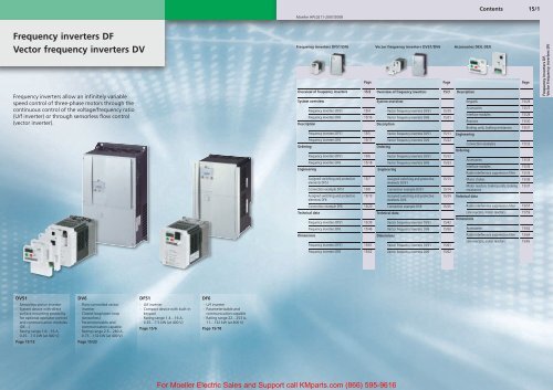
<strong>Frequency</strong> <strong>inverters</strong> <strong>DF</strong><br />
<strong>Vector</strong> <strong>frequency</strong> <strong>inverters</strong> <strong>DV</strong><br />
<strong>Frequency</strong> <strong>inverters</strong> allow an infinitely variable<br />
speed control of three-phase motors through the<br />
continuous control of the voltage/<strong>frequency</strong> ratio<br />
(U/f inverter) or through sensorless flow control<br />
(vector inverter).<br />
<strong>Frequency</strong> <strong>inverters</strong> <strong>DF</strong>51/<strong>DF</strong>6<br />
Page<br />
Overview of <strong>frequency</strong> <strong>inverters</strong> 15/2<br />
System overview<br />
<strong>Frequency</strong> <strong>inverters</strong> <strong>DF</strong>51 15/4<br />
<strong>Frequency</strong> <strong>inverters</strong> <strong>DF</strong>6 15/16<br />
Description<br />
<strong>Frequency</strong> <strong>inverters</strong> <strong>DF</strong>51 15/5<br />
<strong>Frequency</strong> <strong>inverters</strong> <strong>DF</strong>6 15/17<br />
Ordering<br />
<strong>Frequency</strong> <strong>inverters</strong> <strong>DF</strong>51 15/6<br />
<strong>Frequency</strong> <strong>inverters</strong> <strong>DF</strong>6 15/18<br />
Engineering<br />
Assigned switching and protective<br />
elements <strong>DF</strong>51<br />
15/7<br />
Connection example <strong>DF</strong>51 15/8<br />
Assigned switching and protective<br />
elements <strong>DF</strong>6<br />
15/19<br />
Connection example <strong>DF</strong>6 15/20<br />
Technical data<br />
Dimensions<br />
<strong>Frequency</strong> <strong>inverters</strong> <strong>DF</strong>51 15/39<br />
<strong>Frequency</strong> <strong>inverters</strong> <strong>DF</strong>6 15/46<br />
<strong>Frequency</strong> <strong>inverters</strong> <strong>DF</strong>51 15/61<br />
<strong>Vector</strong> <strong>frequency</strong> <strong>inverters</strong> <strong>DV</strong>51/<strong>DV</strong>6<br />
Page<br />
Overview of <strong>frequency</strong> <strong>inverters</strong> 15/3<br />
System overview<br />
<strong>Vector</strong> <strong>frequency</strong> <strong>inverters</strong> <strong>DV</strong>51 15/10<br />
<strong>Vector</strong> <strong>frequency</strong> <strong>inverters</strong> <strong>DV</strong>6 15/21<br />
Description<br />
<strong>Vector</strong> <strong>frequency</strong> <strong>inverters</strong> <strong>DV</strong>51 15/11<br />
<strong>Vector</strong> <strong>frequency</strong> <strong>inverters</strong> <strong>DV</strong>6 15/22<br />
Ordering<br />
<strong>Vector</strong> <strong>frequency</strong> <strong>inverters</strong> <strong>DV</strong>51 15/12<br />
<strong>Vector</strong> <strong>frequency</strong> <strong>inverters</strong> <strong>DV</strong>6 15/23<br />
Engineering<br />
Assigned switching and protective<br />
elements <strong>DV</strong>51<br />
15/13<br />
Connection example <strong>DV</strong>51 15/14<br />
Assigned switching and protective<br />
elements <strong>DV</strong>6<br />
15/24<br />
Connection example <strong>DV</strong>6 15/25<br />
Technical data<br />
<strong>Vector</strong> <strong>frequency</strong> <strong>inverters</strong> <strong>DV</strong>51 15/42<br />
<strong>Vector</strong> <strong>frequency</strong> <strong>inverters</strong> <strong>DV</strong>6 15/50<br />
Dimensions<br />
<strong>Vector</strong> <strong>frequency</strong> <strong>inverters</strong> <strong>DV</strong>51 15/61<br />
Accessories DEV, DEX<br />
Description<br />
Page<br />
Keypads 15/26<br />
Accessories 15/27<br />
Interface modules 15/28<br />
Reactors 15/30<br />
Braking units, braking resistances 15/31<br />
Engineering<br />
Connection examples 15/32<br />
Ordering<br />
Accessories 15/33<br />
Interface modules 15/34<br />
Radio interference suppression filter 15/35<br />
Mains chokes 15/36<br />
Motor reactors, braking units, braking 15/37<br />
resistances<br />
Technical data<br />
Radio interference suppression filter 15/57<br />
Line reactors, motor reactors 15/59<br />
Dimensions<br />
Accessories 15/62<br />
Radio interference suppression filter 15/64<br />
Line reactors, motor reactors 15/65<br />
<strong>Frequency</strong> <strong>inverters</strong> <strong>DF</strong>,<br />
<strong>Vector</strong> <strong>frequency</strong> <strong>inverters</strong> <strong>DV</strong><br />
<strong>Frequency</strong> <strong>inverters</strong> <strong>DF</strong>6 15/62<br />
<strong>Vector</strong> <strong>frequency</strong> <strong>inverters</strong> <strong>DV</strong>6 15/62<br />
<strong>DV</strong>51<br />
- Sensorless vector inverter<br />
- System device with direct<br />
surface mounting possibility<br />
for optional operator control<br />
and communication modules<br />
(DE…)<br />
- Rating range 1.6…16 A,<br />
0.25…7.5 kW (at 400 V)<br />
Page 15/12<br />
<strong>DV</strong>6<br />
- Flow-controlled vector<br />
inverter<br />
- Closed-loop/open-loop<br />
(sensorless)<br />
- Parameterizable and<br />
communication-capable<br />
- Rating range 2.5…260 A,<br />
0.75…132 kW (at 400 V)<br />
Page 15/23<br />
<strong>DF</strong>51<br />
- U/f inverter<br />
- Compact device with built-in<br />
keypad<br />
- Rating range 1.4…16 A,<br />
0.25…7.5 kW (at 400 V)<br />
Page 15/6<br />
<strong>DF</strong>6<br />
- U/f inverter<br />
- Parameterizable and<br />
communication-capable<br />
- Rating range 22…253 A,<br />
11…132 kW (at 400 V)<br />
Page 15/18<br />
For <strong>Moeller</strong> Electric Sales and Support call KMparts.com (866) 595-9616
15/2<br />
<strong>Frequency</strong> Inverters – Overview<br />
<strong>DF</strong>51, <strong>DF</strong>6<br />
<strong>Moeller</strong> HPL0211-2007/2008<br />
http://catalog.moeller.net<br />
U/f <strong>inverters</strong> <strong>DF</strong>51-320 <strong>DF</strong>51-322 <strong>DF</strong>51-340 <strong>DF</strong>6-340<br />
<strong>Frequency</strong> <strong>inverters</strong><br />
<strong>Vector</strong> <strong>frequency</strong> <strong>inverters</strong><br />
Rated voltage<br />
230 V AC 230 V AC 400 V AC 400 V AC<br />
(50/60Hz g5%)<br />
1 AC 180…264 V g 0% – K – –<br />
3 AC 180…264 V g 0% K K – –<br />
3 AC 342…528 V g 0% – – K K<br />
Rated operational current 15.9…32 A 1.4…10 A 1.5…16 A 22 … 230 A<br />
Assigned motor rating at rated voltage 4…7.5 kW 0.25…7.5 kW 0.37…7.5 kW 11 … 132 kW<br />
PID controller K K K K<br />
Built-in braking chopper (external braking resistance) – – – Only <strong>DF</strong>6-340-11K<br />
and <strong>DF</strong>6-340-15K<br />
Keypad K K K K<br />
Communication interface RS 485, Modbus RTU (optionally PROFIBUS-DP, CANopen) RS 422, RS 485, (optionally<br />
PROFIBUS-DP)<br />
Product standard EN 50178, IEC 61800-3<br />
Approvals CE, UL, c-UL, cTick CE, UL, c-UL,CSA, cTick<br />
Degree of protection<br />
IP20<br />
Ambient temperature<br />
Operating temperature °C -10 to +40 with rated current I e at a clock <strong>frequency</strong> of 5 kHz; up to +50 °C at a reduced clock <strong>frequency</strong> of 2 kHz<br />
and reduced output current of 80 % I e .<br />
Storage °C –25…+70<br />
Mechanical shock resistance<br />
Vibration and impact, max. 5.9 m/s 2 (0.6 g) at 10 to 55 Hz<br />
Pollution degree VDE 0110 Part 2, pollution degree 2<br />
Climatic proofing Class 3K3 according to EN 50178 (non-condensing, average relative humidity 20 to 90 %)<br />
Altitude m 0 to 1000 m a.s.l., above 1000 m with reduced current (2.5 %/100 m)<br />
Mounting position<br />
Vertically suspended<br />
Free surrounding areas<br />
100 mm above and below device<br />
Emitted interference IEC/EN 61800-3 (EN 55011 group 1 class B)<br />
Noise immunity<br />
IEC/EN 61800-3, industrial environment<br />
Insulation resistance Overvoltage category III according to VDE 0110<br />
Leakage current to PE mA < 3.5 (to EN 50178)<br />
Contact protection<br />
Finger and back-of-hand proof<br />
Protective isolation from switching<br />
Safe isolation from the mains. Double basic isolation (to EN 50178)<br />
circuitry<br />
Protective measures<br />
Overcurrent, earth fault, overvoltage, undervoltage, overload, overtemperature, electronic overload protection:<br />
I 2 t monitoring and PTC input (thermistor or thermostat)<br />
Notes<br />
If the <strong>frequency</strong> inverter is to be installed in an enclosure, control panel or similar housing, the ambient temperature Ta is<br />
taken to be the temperature inside this enclosure or control panel.<br />
All rating data of the power section is based on a switching <strong>frequency</strong> of 5 kHz (default setting) and an ambient temperature<br />
of +40 °C, for operation of a four-pole three-phase asynchronous motor.<br />
For <strong>Moeller</strong> Electric Sales and Support call KMparts.com (866) 595-9616
<strong>Frequency</strong> Inverters – Overview<br />
15/3<br />
http://catalog.moeller.net<br />
<strong>Moeller</strong> HPL0211-2007/2008<br />
<strong>DV</strong>51<br />
<strong>Vector</strong> <strong>inverters</strong> <strong>DV</strong>51-320 <strong>DV</strong>51-322 <strong>DV</strong>51-340 <strong>DV</strong>6-340<br />
Rated voltage<br />
230 V AC 230 V AC 400 V AC 400 V AC<br />
(50/60Hz g5%)<br />
1 AC 180…264 V g 0 % – K – –<br />
3 AC 180…264 V g 0 % K K – –<br />
3 AC 342…528 V g 0 % – – K K<br />
Rated operational current 17.5…32 A 1.6…11 A 1.5…16 A 2.8…286 A<br />
Assigned motor rating at rated voltage 4…7.5 kW 0.25…7.5 kW 0,37…7.5 kW 0.75 … 132 kW<br />
PID controller K K K K<br />
Built-in braking chopper (external braking resistance) K K K <strong>DV</strong>6-340-075 …<br />
<strong>DV</strong>6-340-11K<br />
Keypad Option DEX-KEY-6…, DEX-KEY-10 K<br />
Communication interface RS 485, Modbus RTU (optionally PROFIBUS-DP, CANopen) RS 422, RS 485, (optionally<br />
PROFIBUS-DP)<br />
Product standard EN 50178, IEC 61800-3<br />
Approvals CE, UL, c-UL, cTick CE, UL, c-UL,CSA, cTick<br />
Degree of protection<br />
IP20<br />
<strong>Frequency</strong> <strong>inverters</strong><br />
<strong>Vector</strong> <strong>frequency</strong> <strong>inverters</strong><br />
Ambient temperature<br />
Operating temperature °C -10 to +40 with rated current I e at a clock <strong>frequency</strong> of 5 kHz; up to +50 °C at a reduced clock <strong>frequency</strong> of 2 kHz<br />
and reduced output current of 80 % I e .<br />
Storage °C –25…+70<br />
Mechanical shock resistance<br />
Vibration and impact, max. 5.9 m/s 2 (0.6 g) at 10 to 55 Hz<br />
Pollution degree VDE 0110 Part 2, pollution degree 2<br />
Climatic proofing Class 3K3 according to EN 50178 (non-condensing, average relative humidity 20 to 90 %)<br />
Altitude m 0 to 1000 m a.s.l., above 1000 m with reduced current (2.5 %/100 m)<br />
Mounting position<br />
Vertically suspended<br />
Free surrounding areas<br />
100 mm above and below device<br />
Emitted interference IEC/EN 61800-3 (EN 55011 group 1 class B)<br />
Noise immunity<br />
IEC/EN 61800-3, industrial environment<br />
Insulation resistance Overvoltage category III according to VDE 0110<br />
Leakage current to PE mA < 3.5 (to EN 50178)<br />
Contact protection<br />
Finger and back-of-hand proof<br />
Protective isolation from switching<br />
Safe isolation from the mains. Double basic isolation (to EN 50178)<br />
circuitry<br />
Protective measures<br />
Overcurrent, earth fault, overvoltage, undervoltage, overload, overtemperature, electronic overload protection:<br />
I 2 t monitoring and PTC input (thermistor or thermostat)<br />
Notes<br />
If the <strong>frequency</strong> inverter is to be installed in an enclosure, control panel or similar housing, the ambient temperature T a is<br />
taken to be the temperature inside this enclosure or control panel.<br />
All rating data of the power section is based on a switching <strong>frequency</strong> of 5 kHz (default setting) and an ambient temperature<br />
of +40 °C, for operation of a four-pole three-phase asynchronous motor.<br />
For <strong>Moeller</strong> Electric Sales and Support call KMparts.com (866) 595-9616
READ COPY<br />
For <strong>Moeller</strong> Electric Sales and Support call KMparts.com (866) 595-9616<br />
15/4<br />
System overview<br />
<strong>Frequency</strong> <strong>inverters</strong><br />
<strong>DF</strong>51<br />
<strong>Moeller</strong> HPL0211-2007/2008<br />
http://catalog.moeller.net<br />
9<br />
8<br />
<strong>Frequency</strong> <strong>inverters</strong><br />
<strong>Vector</strong> <strong>frequency</strong> <strong>inverters</strong><br />
Hz<br />
A<br />
RUN<br />
PRG<br />
PRG ENTER<br />
POWER<br />
ALARM<br />
1<br />
2<br />
POWER<br />
7<br />
ALARM<br />
PRG<br />
POWER<br />
RUN<br />
Hz<br />
A<br />
RUN<br />
PRG<br />
Hz<br />
A<br />
RUN<br />
ALARM<br />
PRG ENTER<br />
RMT<br />
COPY<br />
MNT<br />
PRG<br />
ENTER<br />
FWD<br />
REV<br />
6<br />
3<br />
5<br />
4<br />
Base units System accessories Accessories<br />
<strong>Frequency</strong> <strong>inverters</strong> 1 Communication modules 6 Radio interference suppression filter 2<br />
<strong>DF</strong>51-322-... CANopen interface a page 15/35<br />
Mains: 230 V single-phase/3-phase PROFIBUS-DP interface Mains reactors 3<br />
Motor rating from 0.25 to 2.2 kW (230 V) a page 15/34 a page 15/36<br />
a page 15/6 Mounting frame 5 Motor reactor 3<br />
for commumication modules a page 15/37<br />
<strong>DF</strong>51-320-... 1 a page 15/34 Connection cable 4<br />
Mains: 230 V 3-phase<br />
Connection cable for external LCD keypad<br />
Motor ratings<br />
a page 15/33<br />
from 4 to 7.5 kW (230 V)<br />
a page 15/6 Keypads 7, 8<br />
External LCD keypad with/without memory<br />
function<br />
<strong>DF</strong>51-340-... 1 a page 15/33<br />
Mains: 400 V 3-phase Mounting frame 9<br />
Motor rating<br />
from 0.37 to 7.5 kW (400 V)<br />
Mounting frame for external<br />
LCD keypad<br />
a page 15/6 a page 15/33
For <strong>Moeller</strong> Electric Sales and Support call KMparts.com (866) 595-9616<br />
http://catalog.moeller.net<br />
<strong>Moeller</strong> HPL0211-2007/2008<br />
Description<br />
<strong>Frequency</strong> Inverters<br />
<strong>DF</strong>51<br />
15/5<br />
<strong>Frequency</strong> <strong>inverters</strong> <strong>DF</strong>51<br />
vector <strong>frequency</strong> <strong>inverters</strong> <strong>DV</strong>51<br />
Application<br />
The <strong>frequency</strong> <strong>inverters</strong> of the <strong>DF</strong>51 series provide infinitely variable speed control<br />
of three-phase motors. They are especially suitable for applications where simple<br />
operation and economic efficiency are important.<br />
The assigned performance range for four-pole three-phase asynchronous motors<br />
ranges from:<br />
• 0.25 to 2.2 kW with single-phase power supply (230 V)<br />
• 0.25 to 7.5 kW with three-phase power supply (230 V)<br />
• 0.37 to 7.5 kW with three-phase power supply (400 V)<br />
The <strong>frequency</strong> inverter <strong>DF</strong>51 can be used as a stand-alone drive or incorporated in<br />
automation systems. With its / (voltage/<strong>frequency</strong>) characteristic control, it can be<br />
used in wide range of applications, from simple pump and fan drives through<br />
standard transportation and conveying applications to flexible use the machine tool<br />
and packaging machine industry.<br />
Features<br />
• Compact construction due to highly-integrated module technology<br />
• Integrated keypad with four-character seven-segment display, LEDs, six<br />
function keys and a setpoint value potentiometer<br />
• Serial interface (RS 485, Modbus RTU)<br />
• Five digital inputs (24 V DC)<br />
• Two digital outputs (24 V DC)<br />
• Two analog inputs (0 to +10 V, 4 to 20 mA)<br />
• One analog output (0 to +10 V)<br />
• A relay (changeover contact: 24 V DC/230 V AC)<br />
• Thermistor input<br />
• User-friendly direct operation without prior configuration.<br />
• Conformance to global standards CE, UL, c-UL and cTick<br />
Functions<br />
Comprehensive protective functions guarantee safe operation and protect<br />
<strong>frequency</strong> <strong>inverters</strong> and motors:<br />
• Overcurrent, earth fault<br />
• Overload, electronic motor protection<br />
• Overtemperature<br />
• Overvoltage, undervoltage<br />
• Restart inhibit<br />
Additional operational functions:<br />
• > 100 % starting torque from about 6 Hz<br />
• PID controller<br />
• Automatic voltage control (boost)<br />
• Min./max. <strong>frequency</strong> limitation<br />
• Electronic motor potentiometer function<br />
• <strong>Frequency</strong> hopping (<strong>frequency</strong> masking)<br />
• DC braking to motor standstill<br />
• Up to 16 fixed speeds<br />
• PLC functionality: Linkage of digital in- and outputs<br />
Documentation<br />
• Each <strong>DF</strong>51 vector <strong>frequency</strong> inverter is supplied with installation instructions<br />
and a CD.<br />
• The AWA contains a short description with illustrations and information about<br />
correct handling, installation and electrical connection of the device. The<br />
information supplied is printed in seven languages (English, Chinese, French,<br />
German, Italian, Russian, and Spanish).<br />
• The CD contains a detailed manual (at least English, German) and configuration<br />
software with help text.<br />
• Documentation and parameterization software are also available for download<br />
from the Internet:www.moeller.net/support<br />
Note:<br />
The software on the CD can be run on PCs with the current Windows operating<br />
systems (from 98 to XP). For connecting a PC (RS 232) to a <strong>DF</strong>51 <strong>frequency</strong> inverter,<br />
you will need the connection cable DEX-CBL-2M0-PC.
15/6<br />
Ordering<br />
<strong>Frequency</strong> <strong>inverters</strong><br />
<strong>DF</strong>51<br />
<strong>Moeller</strong> HPL0211-2007/2008<br />
http://catalog.moeller.net<br />
Rated voltage<br />
Max. rated<br />
operational current<br />
Rated power for<br />
motors<br />
Part no.<br />
Article no.<br />
Price<br />
see price list<br />
Std. pack<br />
<strong>Frequency</strong> <strong>inverters</strong><br />
<strong>Vector</strong> <strong>frequency</strong> <strong>inverters</strong><br />
U e<br />
V A P<br />
kW<br />
<strong>Frequency</strong> Inverters <strong>DF</strong>51<br />
<strong>Frequency</strong> <strong>inverters</strong> 0.25 kW to 2.2 kW at 230 V, one- and three-phase connection<br />
1 AC 180…264 V g 0 %<br />
3 AC 180…264 V g 0 %<br />
1 AC 180…264 V g 0 %<br />
3 AC 180…264 V g 0 %<br />
1 AC 180…264 V g 0 %<br />
3 AC 180…264 V g 0 %<br />
1 AC 180…264 V g 0 %<br />
3 AC 180…264 V g 0 %<br />
1 AC 180…264 V g 0 %<br />
3 AC 180…264 V g 0 %<br />
1 AC 180…264 V g 0 %<br />
3 AC 180…264 V g 0 %<br />
1 AC 180…264 V g 0 %<br />
3 AC 180…264 V g 0 %<br />
I e<br />
1.4 0.25 <strong>DF</strong>51-322-025<br />
289102<br />
2.6 0.37 <strong>DF</strong>51-322-037<br />
289103<br />
3 0.55 <strong>DF</strong>51-322-055<br />
289104<br />
4 0.75 <strong>DF</strong>51-322-075<br />
289105<br />
5 1.1 <strong>DF</strong>51-322-1K1<br />
289106<br />
7.1 1.5 <strong>DF</strong>51-322-1K5<br />
289107<br />
10 2.2 <strong>DF</strong>51-322-2K2<br />
289108<br />
1 off<br />
<strong>Frequency</strong> <strong>inverters</strong> 4 kW to 7 kW at 230 V, three-phase connection 1)<br />
3 AC 180…264 V g 0 % 15.9 4 <strong>DF</strong>51-320-4K0<br />
289109<br />
1 off<br />
3 AC 180…264 V g 0 % 24 5.5 <strong>DF</strong>51-320-5K5<br />
289120<br />
3 AC 180…264 V g 0 % 32 7.5 <strong>DF</strong>51-320-7K5<br />
289121<br />
<strong>Frequency</strong> <strong>inverters</strong> 0.37 kW to 7.5 kW at 400 V, three-phase connection<br />
3 AC 342…528 V g 0 % 1.5 – <strong>DF</strong>51-340-037<br />
289122<br />
3 AC 342…528 V g 0 % 2.5 – <strong>DF</strong>51-340-075<br />
289123<br />
3 AC 342…528 V g 0 % 3.8 – <strong>DF</strong>51-340-1K5<br />
289124<br />
3 AC 342…528 V g 0 % 5.5 – <strong>DF</strong>51-340-2K2<br />
289125<br />
3 AC 342…528 V g 0 % 7.8 – <strong>DF</strong>51-340-3K0<br />
289126<br />
3 AC 342…528 V g 0 % 8.6 – <strong>DF</strong>51-340-4K0<br />
289127<br />
3 AC 342…528 V g 0 % 13 – <strong>DF</strong>51-340-5K5<br />
289128<br />
3 AC 342…528 V g 0 % 16 – <strong>DF</strong>51-340-7K5<br />
289129<br />
1 off<br />
Notes<br />
1) All rating data of the power section is based on a switching <strong>frequency</strong> of 5 kHz (default setting) and an ambient temperature of +40 °C, for<br />
operation of a four-pole three-phase asynchronous motor.<br />
For <strong>Moeller</strong> Electric Sales and Support call KMparts.com (866) 595-9616
Engineering<br />
<strong>Frequency</strong> <strong>inverters</strong><br />
15/7<br />
http://catalog.moeller.net<br />
<strong>Moeller</strong> HPL0211-2007/2008<br />
<strong>DF</strong>51<br />
Motor <strong>Frequency</strong> <strong>inverters</strong> Power supply Motor<br />
connection<br />
Assigned<br />
motor rating<br />
Rated<br />
operational<br />
current<br />
Mains<br />
current<br />
Without<br />
mains<br />
reactor/<br />
filter<br />
P I e I N<br />
kW A A<br />
<strong>Frequency</strong> <strong>inverters</strong> <strong>DF</strong>51<br />
Single-phase power supply (230 V AC)<br />
Short-circuit and<br />
line protection<br />
(fuse)<br />
Mains contactor Mains reactor 1) Radio<br />
interference<br />
suppression filter<br />
Motor reactor<br />
<strong>Frequency</strong> <strong>inverters</strong><br />
<strong>Vector</strong> <strong>frequency</strong> <strong>inverters</strong><br />
<strong>DF</strong>51-322-025 0.25 1.4 3.1 FAZ-B10/1N 3) DILM7 DEX-LN1-006 DE51-LZ1-007-V2 DEX-LM3-005<br />
<strong>DF</strong>51-322-037 0.37 2.6 5.8 FAZ-B10/1N 3) DILM7 DEX-LN1-006 DE51-LZ1-007-V2 DEX-LM3-005<br />
<strong>DF</strong>51-322-055 0.55 3 6.7 FAZ-B10/1N 3) DILM7 DEX-LN1-009 DE51-LZ1-007-V2 DEX-LM3-005<br />
<strong>DF</strong>51-322-075 0.75 4 9 FAZ-B16/1N 3) DILM7 DEX-LN1-009 DE51-LZ1-012-V2 DEX-LM3-005<br />
<strong>DF</strong>51-322-1K1 1.1 5 11.2 FAZ-B16/1N 3) DILM7 DEX-LN1-013 DE51-LZ1-012-V2 DEX-LM3-005<br />
<strong>DF</strong>51-322-1K5 1.5 7.1 16 FAZ-B20/1N 3) DILM7 DEX-LN1-018 DE51-LZ1-024-V2 DEX-LM3-008<br />
<strong>DF</strong>51-322-2K2 2.2 10 22.5 FAZ-B32/1N 3) DILM7+DILM12-XP1 DEX-LN1-024 DE51-LZ1-024-V2 DEX-LM3-011<br />
<strong>Frequency</strong> <strong>inverters</strong> <strong>DF</strong>51<br />
Three-phase power supply (230 V AC)<br />
<strong>DF</strong>51-322-025 0.25 1.4 1.8 PKM0-10 DILM7 DEX-LN3-004 DE51-LZ3-007-V4 DEX-LM3-005<br />
<strong>DF</strong>51-322-037 0.37 2.6 3.4 PKM0-10 DILM7 DEX-LN3-004 DE51-LZ3-007-V4 DEX-LM3-005<br />
<strong>DF</strong>51-322-055 0.55 3 3.9 PKM0-10 DILM7 DEX-LN3-004 DE51-LZ3-007-V4 DEX-LM3-005<br />
<strong>DF</strong>51-322-075 0.75 4 5.2 PKM0-16 DILM7 DEX-LN3-006 DE51-LZ3-007-V4 DEX-LM3-005<br />
<strong>DF</strong>51-322-1K1 1.1 5 6.5 PKM0-16 DILM7 DEX-LN3-006 DE51-LZ3-007-V4 DEX-LM3-005<br />
<strong>DF</strong>51-322-1K5 1.5 7.1 9.3 PKM0-16 DILM7 DEX-LN3-010 DE51-LZ3-011-V4 DEX-LM3-008<br />
<strong>DF</strong>51-322-2K2 2.2 10 13 PKM0-20 DILM7 DEX-LN3-016 DE51-LZ3-020-V4 DEX-LM3-011<br />
<strong>DF</strong>51-320-4K0 4 15.9 20 PKM0-32 DILM17 DEX-LN3-025 – 2) DEX-LM3-016<br />
<strong>DF</strong>51-320-5K5 5.5 24 30 PKZM-40 DILM17 DEX-LN3-040 – 2) DEX-LM3-035<br />
<strong>DF</strong>51-320-7K5 7.5 32 40 PKZM-50 DILM25 DEX-LN3-040 – 2) DEX-LM3-035<br />
<strong>Frequency</strong> <strong>inverters</strong> <strong>DV</strong>51<br />
Three-phase power supply (400 V AC)<br />
<strong>DF</strong>51-340-037 0.37 1.5 2 PKM0-4 DILM7 DEX-LN3-004 DE51-LZ3-007-V4 DEX-LM3-005<br />
<strong>DF</strong>51-340-075 0.75 2.5 3.3 PKM0-6,3 DILM7 DEX-LN3-004 DE51-LZ3-007-V4 DEX-LM3-005<br />
<strong>DF</strong>51-340-1K5 1.5 3.8 5 PKM0-10 DILM7 DEX-LN3-004 DE51-LZ3-007-V4 DEX-LM3-005<br />
<strong>DF</strong>51-340-2K2 2.2 5.5 7 PKM0-10 DILM7 DEX-LN3-006 DE51-LZ3-007-V4 DEX-LM3-008<br />
<strong>DF</strong>51-340-3K0 3 7.8 10 PKM0-16 DILM7 DEX-LN3-010 DE51-LZ3-011-V4 DEX-LM3-008<br />
<strong>DF</strong>51-340-4K0 4 8.6 11 PKM0-16 DILM7 DEX-LN3-010 DE51-LZ3-011-V4 DEX-LM3-011<br />
<strong>DF</strong>51-340-5K5 5.5 13 16.5 PKM0-20 DILM7 DEX-LN3-016 DE51-LZ3-020-V4 DEX-LM3-016<br />
<strong>DF</strong>51-340-7K5 7.5 16 20 PKM0-25 DILM17 DEX-LN3-025 DE51-LZ3-020-V4 DEX-LM3-016<br />
Notes:<br />
1) Mains chokes reduce the line currents by up to 30 % and extend the <strong>frequency</strong> <strong>inverters</strong>’ lifespan.<br />
2) No device assigned yet.<br />
3) Where single-phase <strong>frequency</strong> <strong>inverters</strong> are used on mains without line reactor (for example with reactive-power compensation equipment or UPS),<br />
current peaks can occur when the mains contactor is switched on, and these can cause the FAZ-B... to trip prematurely. Remedy: fit a mains reactor<br />
upstream or use a FAZ-C…<br />
Line protection with FAZ, PKM or PKZM (PKZM0 can be used instead of PKM0) a section 12, 8<br />
Mains contactors DIL a section 5<br />
Main chokes DEX-LN… a page15/36<br />
Motor chokes DEX-LM3-… a page 15/37<br />
SFB400/... sine-wave filters please enquire<br />
For <strong>Moeller</strong> Electric Sales and Support call KMparts.com (866) 595-9616
For <strong>Moeller</strong> Electric Sales and Support call KMparts.com (866) 595-9616<br />
<strong>Frequency</strong> <strong>inverters</strong><br />
<strong>Vector</strong> <strong>frequency</strong> <strong>inverters</strong><br />
15/8<br />
Block diagram <strong>DF</strong>51<br />
Engineering<br />
Connection example<br />
<strong>DF</strong>51<br />
In their default configuration, the <strong>DF</strong>51 <strong>frequency</strong> <strong>inverters</strong> can be used at their<br />
assigned supply voltage and motor rating (four-pole, three-phase asynchronous<br />
motor) without any parameter changes. Their acceleration and deceleration times<br />
are set to 15 seconds. The control signal inputs and outputs have the following<br />
assigned functions:<br />
Terminal 1: FWD = Clockwise rotating field enable (Forward)<br />
Terminal 2: REV = Anticlockwise rotating field enable (Reverse)<br />
Terminal 3: FF1 = Fixed <strong>frequency</strong> 1<br />
<strong>Moeller</strong> HPL0211-2007/2008<br />
http://catalog.moeller.net<br />
Terminal 4: FF2 = Fixed <strong>frequency</strong> 2<br />
Terminal 5: RST = Reset, can be configured as thermistor input with<br />
parameter C005.<br />
Terminal 11: FA1 = <strong>Frequency</strong> arrival, type 1 (output <strong>frequency</strong> actual value<br />
= reference input)<br />
Terminal 12: RUN = Running<br />
Terminals K11- Relay, fault signal (K11-K14 ready for operation)<br />
K12:<br />
Through the built-in keypad, all parameters and functions can be adapted to the<br />
application.<br />
5 L<br />
*<br />
0 V<br />
0...10 V<br />
+10 V<br />
0...10 V<br />
4...20 mA<br />
0 V<br />
U<br />
V<br />
M<br />
3 ~<br />
W<br />
PE<br />
K12 K14<br />
e<br />
K11<br />
AM H O OI L<br />
i<br />
CM2<br />
12 11<br />
FF2<br />
FF1<br />
REV<br />
FWD<br />
RUN<br />
FA1<br />
–<br />
+<br />
L+<br />
DC+<br />
DC–<br />
L<br />
L1<br />
L2<br />
N<br />
L3<br />
PE<br />
PE<br />
1<br />
3<br />
+24 V<br />
4 3 2 1<br />
P24<br />
–<br />
+<br />
* PNU C005 = 19 (PTC)<br />
RJ 45<br />
ModBus<br />
RST
For <strong>Moeller</strong> Electric Sales and Support call KMparts.com (866) 595-9616<br />
http://catalog.moeller.net<br />
<strong>Moeller</strong> HPL0211-2007/2008<br />
Connection example for a 0.75 kW motor with the ratings plate illustrated below.<br />
Variant A: Motor connected in a delta circuit, <strong>DF</strong>51 with single-phase<br />
mains supply (230 V).<br />
Variant B:<br />
Engineering<br />
Connection example<br />
<strong>DF</strong>51<br />
Motor connected in a star circuit, <strong>DF</strong>51 with three-phase mains<br />
supply (400 V).<br />
15/9<br />
Motor: P = 0.75 kW<br />
Mains: 3/N/PE 400 V, 50/60 Hz<br />
EMC-conformant connection examples: power section<br />
FAZ-1N-B16<br />
L<br />
N<br />
PE<br />
F1<br />
1 h 230 V, 50/60 Hz<br />
The 0.75 kW motor described below can be delta-connected to a single-phase 230 V mains (version<br />
A) or star-connected to a 400 V mains.<br />
Depending on the mains voltage, a <strong>DF</strong>5-322 <strong>frequency</strong> inverter is selected for 230 V single-phase<br />
AC, or a <strong>DF</strong>5-340 for 400 V 3-phase AC, together with the corresponding accessories.<br />
PKM0-6,3<br />
L1<br />
L2<br />
L3<br />
PE<br />
Q1<br />
3 h 400 V, 50/60 Hz<br />
<strong>Frequency</strong> <strong>inverters</strong><br />
<strong>Vector</strong> <strong>frequency</strong> <strong>inverters</strong><br />
I<br />
I<br />
I<br />
DILM7<br />
+DILM12-XP1<br />
Q1<br />
a<br />
1<br />
DILM7<br />
Q11<br />
U1<br />
V1<br />
W1<br />
DEX-LN1-009<br />
R1<br />
2<br />
PE<br />
DEX-LN3-004<br />
R1<br />
U2<br />
V2<br />
W2<br />
PE<br />
L<br />
N<br />
L1 L2 L3<br />
K1<br />
PE<br />
K1<br />
PE<br />
DE51-LZ1-012-V2<br />
L<br />
N<br />
PE<br />
DE51-LZ3-007-V4<br />
L1 L2 L3 PE<br />
<strong>DF</strong>51-322-075<br />
<strong>DF</strong>51-340-075<br />
T1<br />
L+ DC+ DC– U V W PE<br />
PES<br />
T1<br />
L+ DC+ DC– U V W PE<br />
PES<br />
PES<br />
PES<br />
X1<br />
X1<br />
PES<br />
PES<br />
PES<br />
PES<br />
M1<br />
M<br />
3 ~<br />
e<br />
M1<br />
M<br />
3 ~<br />
e<br />
U1 V1 W1<br />
U1 V1 W1<br />
W2 U2 V2<br />
W2 U2 V2<br />
230 V<br />
3.5 A<br />
0.75 kW<br />
400 V<br />
2 A<br />
0.75 kW<br />
a<br />
Connection option for single-phase connection of a 2.2 kW drive<br />
(<strong>DF</strong>51-322-2K2) required!<br />
230 / 400 V 4.0 / 2.3 A<br />
S1 0,75 kW cos ϕ 0.67<br />
1410 rpm 50 Hz
READ COPY<br />
For <strong>Moeller</strong> Electric Sales and Support call KMparts.com (866) 595-9616<br />
15/10<br />
System overview<br />
<strong>Vector</strong> <strong>frequency</strong> <strong>inverters</strong><br />
<strong>DV</strong>51<br />
<strong>Moeller</strong> HPL0211-2007/2008<br />
http://catalog.moeller.net<br />
11<br />
<strong>Frequency</strong> <strong>inverters</strong><br />
<strong>Vector</strong> <strong>frequency</strong> <strong>inverters</strong><br />
Hz<br />
A<br />
RUN<br />
PRG<br />
7 1<br />
PRG ENTER<br />
POWER<br />
ALARM<br />
10<br />
2<br />
9<br />
ALARM<br />
PRG<br />
POWER<br />
RUN<br />
POWER<br />
ALARM<br />
RUN<br />
RMT<br />
COPY<br />
MNT<br />
PRG<br />
ENTER<br />
3<br />
FWD<br />
REV<br />
7<br />
8<br />
5<br />
4<br />
OPE<br />
POWER<br />
ALARM<br />
RUN<br />
1 2<br />
OFF<br />
RBUS<br />
6<br />
Basic devices<br />
<strong>Vector</strong> <strong>frequency</strong> <strong>inverters</strong> 1<br />
<strong>DV</strong>51-322-...<br />
Mains: 230 V single-phase/3-phase<br />
Motor rating v<br />
from 0.25 to 2.2 kW (230 V)<br />
a page 15/12<br />
<strong>DV</strong>51-320-... 1<br />
Mains: 230 V 3-phase<br />
Motor rating<br />
from 4 to 7.5 kW (230 V)<br />
a page 15/12<br />
<strong>DV</strong>51-340-... 1<br />
Mains: 400 V 3-phase<br />
Motor rating<br />
from 0.37 to 7.5 kW (400 V)<br />
a page 15/12<br />
System accessories<br />
Communication modules 6<br />
RS 485 T adapter module<br />
a page 15/33<br />
Communication modules 7<br />
CANopen interface<br />
PROFIBUS DP interface<br />
a page 15/34<br />
Mounting frames 8<br />
Adapter for LCD keypad DEX-KEY-6… in<br />
combination with the communication<br />
modules<br />
a page 15/34<br />
Mounting frames 11<br />
For external LCD keypad<br />
a page 15/33<br />
Accessories<br />
Radio interference suppression filter 2<br />
a page 15/35<br />
Line reactors 3<br />
a page 15/36<br />
Motor reactors 3<br />
a page 15/37<br />
Braking resistor 4<br />
Enclosed (IP 20) high-capacity resistors<br />
with temperature switch, for connecting<br />
to the <strong>DV</strong>51’s braking transistor<br />
a page 15/37<br />
Connection cables 5<br />
Connection cable for external display and<br />
control units<br />
a page 15/33<br />
Keypad 9, 10<br />
External keypad with/without<br />
memory function a page 15/33
For <strong>Moeller</strong> Electric Sales and Support call KMparts.com (866) 595-9616<br />
http://catalog.moeller.net<br />
<strong>Moeller</strong> HPL0211-2007/2008<br />
Description<br />
<strong>Vector</strong> <strong>frequency</strong> <strong>inverters</strong><br />
<strong>DV</strong>51<br />
15/11<br />
<strong>Frequency</strong> <strong>inverters</strong><br />
vector <strong>frequency</strong> <strong>inverters</strong><br />
Application<br />
With their sensorless vector control, the <strong>DV</strong>51 <strong>frequency</strong> <strong>inverters</strong> offer excellent<br />
torque levels for three-phase motors with cage rotors. They are especially suitable<br />
for demanding applications in which maximum torque and smooth running are<br />
required at the lower speed range.<br />
The assigned performance range for four-pole three-phase asynchronous motors<br />
ranges from:<br />
• 0.25 to 2.2 kW with single-phase power supply (230 V)<br />
• 0.25 to 7.5 kW with three-phase power supply (230 V)<br />
• 0.37 to 7.5 kW with three-phase power supply (400 V)<br />
The vector <strong>frequency</strong> <strong>inverters</strong> <strong>DV</strong>51 can be used as a stand-alone drive or<br />
incorporated in automation systems. The adaptable modules allow flexible<br />
communication. With the sensorless vector control, applications in the plastics and<br />
metal processing, textile, paper and printing industries and in crane and lift<br />
installations are possible.<br />
Features<br />
• Compact construction due to highly-integrated module technology<br />
• Internal braking transistor<br />
• Optional keypads DEX-KEY-6…<br />
• Optional fieldbus module (CAN, PROFIBUS DP)<br />
• Serial interface (RS 485, Modbus RTU)<br />
• Six digital inputs (24 V DC)<br />
• Two digital outputs (24 V DC)<br />
• Two analog inputs (0 to +10 V, 4 to 20 mA)<br />
• One analog output (0 to +10 V)<br />
• A relay (changeover contact: 24 V DC/230 V AC)<br />
• Thermistor input<br />
• User-friendly direct operation without prior configuration.<br />
• Conformance to global standards CE, UL, c-UL and cTick<br />
Functions<br />
Comprehensive protective functions guarantee safe operation and protect<br />
<strong>frequency</strong> <strong>inverters</strong> and motors:<br />
• Overcurrent, earth fault<br />
• Overload, electronic motor protection<br />
• Overtemperature<br />
• Overvoltage, undervoltage<br />
• Restart inhibit<br />
Additional operational functions:<br />
• Sensorless <strong>Vector</strong> Control<br />
• 200 % starting torque from approx 1 Hz<br />
• Dynamic braking (external braking resistor)<br />
• Electronic motor potentiometer function<br />
• PID controller<br />
• Automatic voltage control (boost)<br />
• Min./max. <strong>frequency</strong> limitation<br />
• <strong>Frequency</strong> hopping (<strong>frequency</strong> masking)<br />
• DC braking to motor standstill<br />
• Up to 16 fixed speeds<br />
• PLC functionality: Linkage of digital in- and outputs<br />
Documentation<br />
• Each vector <strong>frequency</strong> inverter <strong>DV</strong>51 is supplied with an installation instruction<br />
(AWA) and a CD.<br />
• The installation instruction contains a short description with illustrations and<br />
information about correct handling, installation and electrical connection of the<br />
device. The information supplied is printed in seven languages (English,<br />
Chinese, French, German, Italian, Russian, and Spanish).<br />
• The CD contains a detailed manual (at least English, German) and configuration<br />
software with help text.<br />
• Documentation and parameterization software are also available for download<br />
from the Internet:www.moeller.net/support<br />
Note:<br />
The software on the CD can be run on PCs with the current Windows operating<br />
systems (from 98 to XP). For connecting a PC (RS 232) to a vector <strong>frequency</strong> inverter<br />
<strong>DV</strong>51, you will need the connection cable DEX-CBL-2M0-PC (with integrated<br />
interface converter).
15/12<br />
Ordering<br />
<strong>Vector</strong> <strong>frequency</strong> <strong>inverters</strong><br />
<strong>DV</strong>51<br />
<strong>Moeller</strong> HPL0211-2007/2008<br />
http://catalog.moeller.net<br />
Rated voltage<br />
Max. rated operational<br />
current<br />
Rated power for motors<br />
Part no.<br />
Article no.<br />
Price<br />
see price list<br />
Std. pack<br />
U e I e at 230 V 3-phase AC<br />
<strong>Frequency</strong> <strong>inverters</strong><br />
<strong>Vector</strong> <strong>frequency</strong> <strong>inverters</strong><br />
V A P<br />
kW<br />
<strong>Vector</strong> <strong>frequency</strong> <strong>inverters</strong> <strong>DV</strong>51<br />
The <strong>DV</strong>51 vector <strong>frequency</strong> <strong>inverters</strong> are supplied without LCD keypad. Order keypad DEX-KEY-6…<br />
separately.<br />
<strong>Vector</strong> <strong>frequency</strong> <strong>inverters</strong> 0.25 kW to 2.2 kW at 230 V, single- and three-phase connection<br />
1 AC 180…264 V g 0 %<br />
3 AC 180…264 V g 0 %<br />
1.6 0.25 <strong>DV</strong>51-322-025<br />
285016<br />
1 off<br />
1 AC 180…264 V g 0 %<br />
3 AC 180…264 V g 0 %<br />
2.6 0.37 <strong>DV</strong>51-322-037<br />
285017<br />
1 AC 180…264 V g 0 %<br />
3 AC 180…264 V g 0 %<br />
3 0.55 <strong>DV</strong>51-322-055<br />
285018<br />
1 AC 180…264 V g 0 %<br />
3 AC 180…264 V g 0 %<br />
4 0.75 <strong>DV</strong>51-322-075<br />
285019<br />
1 AC 180…264 V g 0 %<br />
3 AC 180…264 V g 0 %<br />
5 1.1 <strong>DV</strong>51-322-1K1<br />
285030<br />
1 AC 180…264 V g 0 %<br />
3 AC 180…264 V g 0 %<br />
8 1.5 <strong>DV</strong>51-322-1K5<br />
285031<br />
1 AC 180…264 V g 0 %<br />
3 AC 180…264 V g 0 %<br />
11 2.2 <strong>DV</strong>51-322-2K2<br />
285032<br />
<strong>Vector</strong> <strong>frequency</strong> <strong>inverters</strong> 4 kW to 7.5 kW at 230 V, three-phase connection 1)<br />
3 AC 180…264 V g 0 % 17.5 4 <strong>DV</strong>51-320-4K0<br />
285033<br />
1 off<br />
3 AC 180…264 V g 0 % 24 5.5 <strong>DV</strong>51-320-5K5<br />
285034<br />
3 AC 180…264 V g 0 % 32 7.5 <strong>DV</strong>51-320-7K5<br />
285035<br />
<strong>Vector</strong> <strong>frequency</strong> <strong>inverters</strong> 0.37 kW to 7.5 kW at 400 V, three-phase connection<br />
3 AC 342…528 V g 0 % 1.5 – <strong>DV</strong>51-340-037<br />
285036<br />
1 off<br />
3 AC 342…528 V g 0 % 2.5 – <strong>DV</strong>51-340-075<br />
285037<br />
3 AC 342…528 V g 0 % 3.8 – <strong>DV</strong>51-340-1K5<br />
285038<br />
3 AC 342…528 V g 0 % 5.5 – <strong>DV</strong>51-340-2K2<br />
285039<br />
3 AC 342…528 V g 0 % 7.8 – <strong>DV</strong>51-340-3K0<br />
285040<br />
3 AC 342…528 V g 0 % 8.6 – <strong>DV</strong>51-340-4K0<br />
285041<br />
3 AC 342…528 V g 0 % 13 – <strong>DV</strong>51-340-5K5<br />
285042<br />
3 AC 342…528 V g 0 % 16 – <strong>DV</strong>51-340-7K5<br />
285043<br />
Notes<br />
All rating data of the power section is based on a switching <strong>frequency</strong> of 5 kHz (default setting) and an ambient temperature of +40 °C, for operation<br />
of a four-pole three-phase asynchronous motor.<br />
For <strong>Moeller</strong> Electric Sales and Support call KMparts.com (866) 595-9616
Engineering<br />
Assigned switching and protective elements<br />
15/13<br />
http://catalog.moeller.net<br />
<strong>Moeller</strong> HPL0211-2007/2008<br />
<strong>DV</strong>51<br />
Motor <strong>Frequency</strong> <strong>inverters</strong> Mains contactor Motor connection<br />
Assigned<br />
motor rating<br />
Rated operational<br />
current<br />
Mains current<br />
Without<br />
mains reactor/filter<br />
Mains fuse Mains contactor Mains choke 1) Radio interference<br />
suppression filter<br />
Motor reactor<br />
P I e I N<br />
kW A A<br />
<strong>Frequency</strong> inverter <strong>DV</strong>51, single-phase<br />
mains connection(230 V AC)<br />
<strong>DV</strong>51-322-025 0.25 1.6 3.5 FAZ-B10/1N 1) DILM7 DEX-LN1-006 DE51-LZ1-007-V2 DEX-LM3-005<br />
<strong>DV</strong>51-322-037 0.37 2.6 5.8 FAZ-B10/1N 1) DILM7 DEX-LN1-006 DE51-LZ1-007-V2 DEX-LM3-005<br />
<strong>DV</strong>51-322-055 0.55 3 6.7 FAZ-B10/1N 1) DILM7 DEX-LN1-009 DE51-LZ1-007-V2 DEX-LM3-005<br />
<strong>DV</strong>51-322-075 0.75 4 9 FAZ-B16/1N 1) DILM7 DEX-LN1-009 DE51-LZ1-012-V2 DEX-LM3-005<br />
<strong>DV</strong>51-322-1K1 1.1 5 11.2 FAZ-B16/1N 1) DILM7 DEX-LN1-013 DE51-LZ1-012-V2 DEX-LM3-005<br />
<strong>DV</strong>51-322-1K5 1.5 8 17.5 FAZ-B20/1N 1) DILM7 DEX-LN1-018 DE51-LZ1-024-V2 DEX-LM3-008<br />
<strong>DV</strong>51-322-2K2 2.2 11 24 FAZ-B32/1N 1) DILM7+DILM12-XP1 DEX-LN1-024 DE51-LZ1-024-V2 DEX-LM3-011<br />
<strong>Frequency</strong> inverter <strong>DV</strong>51 Three-phase<br />
power supply (230 V AC)<br />
<strong>DV</strong>51-322-025 0.25 1.6 2 PKM0-10 DILM7 DEX-LN3-004 DE51-LZ3-007-V4 DEX-LM3-005<br />
<strong>DV</strong>51-322-037 0.37 2.6 3.4 PKM0-10 DILM7 DEX-LN3-004 DE51-LZ3-007-V4 DEX-LM3-005<br />
<strong>DV</strong>51-322-055 0.55 3 3.9 PKM0-10 DILM7 DEX-LN3-004 DE51-LZ3-007-V4 DEX-LM3-005<br />
<strong>DV</strong>51-322-075 0.75 4 5.2 PKM0-16 DILM7 DEX-LN3-006 DE51-LZ3-007-V4 DEX-LM3-005<br />
<strong>DV</strong>51-322-1K1 1.1 5 6.5 PKM0-16 DILM7 DEX-LN3-006 DE51-LZ3-007-V4 DEX-LM3-005<br />
<strong>DV</strong>51-322-1K5 1.5 8 10 PKM0-16 DILM7 DEX-LN3-010 DE51-LZ3-011-V4 DEX-LM3-008<br />
<strong>DV</strong>51-322-2K2 2.2 11 14 PKM0-20 DILM7 DEX-LN3-016 DE51-LZ3-020-V4 DEX-LM3-011<br />
<strong>DV</strong>51-320-4K0 4 17.5 22 PKZM0-32 DILM17 DEX-LN3-025 – 2) DEX-LM3-035<br />
<strong>DV</strong>51-320-5K5 5.5 24 30 PKZM0-40 DILM17 DEX-LN3-040 – 2) DEX-LM3-035<br />
<strong>DV</strong>51-320-7K5 7.5 32 40 PKZM0-50 DILM25 DEX-LN3-040 – 2) DEX-LM3-035<br />
<strong>Frequency</strong> inverter <strong>DV</strong>51 Three-phase<br />
power supply (400 V AC)<br />
<strong>DV</strong>51-340-037 0.37 1.5 2 PKM0-4 DILM7 DEX-LN3-004 DE51-LZ3-007-V4 DEX-LM3-005<br />
<strong>DV</strong>51-340-075 0.75 2.5 3.3 PKM0-6,3 DILM7 DEX-LN3-004 DE51-LZ3-007-V4 DEX-LM3-005<br />
<strong>DV</strong>51-340-1K5 1.5 3.8 5 PKM0-10 DILM7 DEX-LN3-004 DE51-LZ3-007-V4 DEX-LM3-005<br />
<strong>DV</strong>51-340-2K2 2.2 5.5 7 PKM0-10 DILM7 DEX-LN3-006 DE51-LZ3-007-V4 DEX-LM3-008<br />
<strong>DV</strong>51-340-3K0 3 7.8 10 PKM0-16 DILM7 DEX-LN3-010 DE51-LZ3-011-V4 DEX-LM3-008<br />
<strong>DV</strong>51-340-4K0 4 8.6 11 PKM0-16 DILM7 DEX-LN3-010 DE51-LZ3-011-V4 DEX-LM3-011<br />
<strong>DV</strong>51-340-5K5 5.5 13 16.5 PKM0-20 DILM7 DEX-LN3-016 DE51-LZ3-020-V4 DEX-LM3-016<br />
<strong>DV</strong>51-340-7K5 7.5 16 20 PKM0-25 DILM17 DEX-LN3-025 DE51-LZ3-020-V4 DEX-LM3-016<br />
<strong>Frequency</strong> <strong>inverters</strong><br />
<strong>Vector</strong> <strong>frequency</strong> <strong>inverters</strong><br />
Notes:<br />
1) Mains chokes reduce the line currents by up to 30 % and extend the <strong>frequency</strong> <strong>inverters</strong>’ lifespan.<br />
2) No device assigned yet.<br />
3) Where single-phase <strong>frequency</strong> <strong>inverters</strong> are used on mains without mains choke (for example with reactive-power compensation equipment or UPS),<br />
current peaks can occur when the mains contactor is switched on, and these can cause the FAZ-B… to trip prematurely. Remedy: fit a mains reactor<br />
upstream or use a FAZ-C…<br />
Line protection with FAZ, PKM or PKZM (PKZM0 can be used instead of PKM0) a section 8 or 16<br />
DIL mains contactors a section 5<br />
Main chokes DEX-LN… a page 15/36<br />
Motor chokes DEX-LM3-… a page 15/37<br />
SFB400/… sine-wave filters please enquire<br />
For <strong>Moeller</strong> Electric Sales and Support call KMparts.com (866) 595-9616
For <strong>Moeller</strong> Electric Sales and Support call KMparts.com (866) 595-9616<br />
<strong>Frequency</strong> <strong>inverters</strong><br />
<strong>Vector</strong> <strong>frequency</strong> <strong>inverters</strong><br />
15/14<br />
Block diagram <strong>DV</strong>51<br />
Engineering<br />
Connection example<br />
<strong>DV</strong>51<br />
In their default configuration, the <strong>DV</strong>51 vector <strong>frequency</strong> <strong>inverters</strong> can be used at<br />
their assigned supply voltage and motor rating (four-pole, three-phase<br />
asynchronous motor) without any parameter changes. Their acceleration and<br />
deceleration times are set to 15 seconds. The control signal inputs and outputs<br />
have the following assigned functions:<br />
Terminal 1: FWD = Clockwise rotating field enable (Forward)<br />
Terminal 2: REV = Anticlockwise rotating field enable (Reverse)<br />
Terminal 3: FF1 = Fixed <strong>frequency</strong> 1<br />
Terminal 4: FF2 = Fixed <strong>frequency</strong> 2<br />
L<br />
N<br />
PE<br />
1<br />
<strong>Moeller</strong> HPL0211-2007/2008<br />
http://catalog.moeller.net<br />
Terminal 5: RST = Reset, can be configured as thermistor input with<br />
parameter C005.<br />
Terminal 6: 2CH = Second parameter set<br />
Terminal 11: FA1 = <strong>Frequency</strong> arrival, type 1 (output <strong>frequency</strong> actual value<br />
= reference input)<br />
Terminal 12: RUN = Running<br />
Terminals K11- Relay, fault signal (K11-K14 ready for operation)<br />
K12:<br />
Through optional keypad DEX-KEY-..., all parameters and functions can be adapted<br />
to the application.<br />
+24 V<br />
3<br />
2CH<br />
FF2<br />
FF1<br />
REV<br />
L1<br />
L2<br />
L3<br />
PE<br />
L+<br />
–<br />
+<br />
R Br<br />
DC+<br />
DC–<br />
BR<br />
–<br />
+<br />
U<br />
V<br />
W<br />
PE<br />
K12 K14<br />
K11<br />
5 L<br />
AM H O OI L 12 11<br />
*<br />
0 V<br />
0...10 V<br />
+10 V<br />
0...10 V<br />
4...20 mA<br />
0 V<br />
RUN<br />
FA1<br />
FWD<br />
6 4 3 2 1<br />
P24<br />
CM2<br />
RJ 45<br />
ModBus<br />
M<br />
3 ~<br />
e<br />
RST<br />
i<br />
* PNU C005 = 19 (PTC)
For <strong>Moeller</strong> Electric Sales and Support call KMparts.com (866) 595-9616<br />
1<br />
2<br />
http://catalog.moeller.net<br />
<strong>Moeller</strong> HPL0211-2007/2008<br />
<strong>Vector</strong> <strong>frequency</strong> <strong>inverters</strong> <strong>DV</strong>51 with DEV51–NET–TC module (RS 485 T adapter)<br />
Actuation<br />
Engineering<br />
Connection example<br />
<strong>DV</strong>51<br />
15/15<br />
Q1<br />
S1<br />
SP<br />
R BUS<br />
SN<br />
Host computer<br />
POWER<br />
ALARM<br />
RUN<br />
1 2<br />
OFF<br />
OPE<br />
RBUS<br />
OPE<br />
RBUS<br />
1 2 OPE<br />
RBUS<br />
POWER<br />
ALARM<br />
RUN<br />
1 2<br />
OFF<br />
OPE<br />
RBUS<br />
1 2<br />
OFF<br />
OFF<br />
POWER<br />
ALARM<br />
RUN<br />
OFF<br />
OPE<br />
RBUS<br />
1 2<br />
OFF<br />
OPE<br />
RBUS<br />
6<br />
5<br />
R BUS<br />
<strong>Frequency</strong> <strong>inverters</strong><br />
<strong>Vector</strong> <strong>frequency</strong> <strong>inverters</strong><br />
S2<br />
Q11<br />
6 5 6 5<br />
6 5 6 5<br />
6 5 6 5<br />
Host<br />
computer<br />
1<br />
2<br />
32<br />
Q11<br />
M1 M2 Mn<br />
Wiring<br />
L1<br />
L2<br />
L3<br />
PE<br />
Q1<br />
3 h 400 V, 50/60 Hz<br />
I<br />
I<br />
I<br />
PE<br />
Q11<br />
L1 L2 L3<br />
K1<br />
PE<br />
L1 L2 L3 PE<br />
FWD<br />
T1<br />
L+ DC+ DC– U V W PE BR<br />
1 P24<br />
X1<br />
PES<br />
PES<br />
PES<br />
PES<br />
PE<br />
Enable<br />
Host computer<br />
M1<br />
M<br />
3 ~<br />
e
4<br />
C<br />
READ COPY<br />
For <strong>Moeller</strong> Electric Sales and Support call KMparts.com (866) 595-9616<br />
15/16<br />
System overview<br />
<strong>Frequency</strong> <strong>inverters</strong><br />
<strong>DF</strong>6<br />
<strong>Moeller</strong> HPL0211-2007/2008<br />
http://catalog.moeller.net<br />
<strong>Frequency</strong> <strong>inverters</strong><br />
<strong>Vector</strong> <strong>frequency</strong> <strong>inverters</strong><br />
TM1<br />
2<br />
A<br />
SEQ<br />
CMB<br />
CMB<br />
B<br />
6<br />
5<br />
123<br />
7<br />
8<br />
0<br />
9<br />
F<br />
A B<br />
D<br />
E<br />
C<br />
D<br />
TM2<br />
6<br />
1<br />
2<br />
ALARM<br />
PRG<br />
POWER<br />
RUN<br />
5<br />
RMT<br />
COPY<br />
MNT<br />
PRG<br />
ENTER<br />
FWD<br />
REV<br />
4<br />
3<br />
Base units<br />
<strong>Frequency</strong> <strong>inverters</strong> 1<br />
<strong>DF</strong>6-340-...<br />
Mains: 400 V 3-phase<br />
Motor rating from 11 to 132 kW (400 V)<br />
a page 15/18<br />
System accessories<br />
Keypads 5<br />
External LCD keypad with/without memory<br />
function<br />
a page 15/33<br />
Mounting frames<br />
For external LCD keypad<br />
a page 15/33<br />
Accessories<br />
Radio interference suppression filter 2<br />
a page 15/23<br />
Line reactors 3<br />
a page 15/36<br />
Motor chokes 2<br />
a page 15/37<br />
Braking resistor 4<br />
Enclosed (IP 20) high-capacity resistors<br />
with temperature switch, for connecting to<br />
the braking transistor<br />
a page 15/37<br />
Connection cable for external display and<br />
control units<br />
a page 15/33<br />
Communication modules 6<br />
PROFIBUS DP interface<br />
Encoder interfacing assembly<br />
a page 15/34
For <strong>Moeller</strong> Electric Sales and Support call KMparts.com (866) 595-9616<br />
http://catalog.moeller.net<br />
<strong>Moeller</strong> HPL0211-2007/2008<br />
Description<br />
<strong>Frequency</strong> inverter<br />
<strong>DF</strong>6<br />
15/17<br />
<strong>Frequency</strong> <strong>inverters</strong><br />
<strong>Vector</strong> <strong>frequency</strong> <strong>inverters</strong><br />
Application<br />
The <strong>DF</strong>6 <strong>frequency</strong> <strong>inverters</strong> provide economic speed control of three-phase motors<br />
in standard applications with square-law load characteristics (pumps, fans).<br />
The assigned performance range for four-pole three-phase asynchronous motors<br />
ranges from 11 kW to 132 kW at 400 V.<br />
The <strong>DF</strong>6 units can be used as stand-alone drives or incorporated in automation<br />
systems. Their U/f(voltage/<strong>frequency</strong>) characteristic control allows their use in a<br />
broad range of applications in pump, fan, heating and air conditioning systems as<br />
well as all areas of process engineering with flow control.<br />
Features<br />
• Compact construction<br />
• Plug-in keypad (external installation possible) with four-character sevensegment<br />
display, six function keys and a setpoint value potentiometer<br />
• RS 485 and RS 422 serial interface<br />
• Six digital inputs (24 V DC)<br />
• 3 analog inputs (0 to +10 V, g10 V, 4 to 20 mA)<br />
• Three relays (a changeover contact, two make contacts: 24 V DC/230 V AC)<br />
• Thermistor input<br />
• Bus interface (PROFIBUS DP) can be integrated.<br />
• Global standards conforming to CE, UL, cUL, CSA and cTick<br />
Note:<br />
The <strong>DF</strong>6-340-11K and <strong>DF</strong>6-340-15K <strong>frequency</strong> <strong>inverters</strong> have an integrated braking<br />
chopper and allow direct connection to the braking resistors DE4-BR1-…. For more<br />
than 15 kW the braking device DE4-BU4-1 is necessary for actuating the braking<br />
resistors.<br />
Function<br />
Comprehensive protective functions guarantee safe operation and protect<br />
<strong>frequency</strong> <strong>inverters</strong> and motors:<br />
• Overcurrent, earth fault<br />
• Overload, electronic motor protection<br />
• Overtemperature<br />
• Overvoltage, undervoltage<br />
•Phase failure<br />
Two parameter sets with a wide range of functions:<br />
• PID controller<br />
• Automatic energy saving mode<br />
• Motor synchronization and flying restart circuit<br />
• User macro storage<br />
• Automatic restart after a power failure<br />
• Electronic motor potentiometer function<br />
• 16 fixed frequencies<br />
• Min./max. <strong>frequency</strong> limitation<br />
Documentation<br />
• Each <strong>DF</strong>6 vector <strong>frequency</strong> inverter is supplied with installation instructions and<br />
a CD.<br />
• The AWA contains a short description with illustrations and information about<br />
correct handling, installation and electrical connection of the device. The<br />
information supplied is printed in seven languages (English, Chinese, French,<br />
German, Italian, Russian, and Spanish).<br />
• The CD contains a detailed manual (at least English, German) and configuration<br />
software with help text.<br />
• Documentation and parameterization software are also available for download<br />
from the Internet:www.moeller.net/support<br />
Note:<br />
The software on the CD can be run on PCs with the current Windows operating<br />
systems (from 98 to XP).<br />
For connecting a PC (RS 232) to a <strong>DF</strong>6 <strong>frequency</strong> inverter (RS 422), you will need the<br />
DEX-CBL-2M0-PC connection cable.
15/18<br />
Ordering<br />
<strong>DF</strong>6 <strong>frequency</strong> inverter<br />
<strong>DF</strong>6<br />
<strong>Moeller</strong> HPL0211-2007/2008<br />
http://catalog.moeller.net<br />
Rated voltage<br />
Max. rated<br />
operational current<br />
Rated power for<br />
motors<br />
Part no.<br />
Article no.<br />
Price<br />
see price list<br />
Std. pack<br />
<strong>Frequency</strong> <strong>inverters</strong><br />
<strong>Vector</strong> <strong>frequency</strong> <strong>inverters</strong><br />
<strong>Frequency</strong> <strong>inverters</strong> 11 … 132 kW at 400 V<br />
342 – 528 V g 0 % 3-<br />
phase AC<br />
U e I e at 400 V 3-phase AC<br />
V A P<br />
kW<br />
22 11 <strong>DF</strong>6-340-11K<br />
231384<br />
29 15 <strong>DF</strong>6-340-15K<br />
231385<br />
1 off<br />
37 18.5 <strong>DF</strong>6-340-18K5<br />
231386<br />
43 22 <strong>DF</strong>6-340-22K<br />
231387<br />
57 30 <strong>DF</strong>6-340-30K<br />
231388<br />
70 37 <strong>DF</strong>6-340-37K<br />
231389<br />
85 45 <strong>DF</strong>6-340-45K<br />
231390<br />
105 55 <strong>DF</strong>6-340-55K<br />
231391<br />
135 75 <strong>DF</strong>6-340-75K<br />
231392<br />
160 90 <strong>DF</strong>6-340-90K<br />
231393<br />
195 110 <strong>DF</strong>6-340-110K<br />
231394<br />
230 132 <strong>DF</strong>6-340-132K<br />
231395<br />
Notes<br />
Rated operational current with a switching <strong>frequency</strong> of 5 kHz and an ambient temperature of +40 °C.<br />
For <strong>Moeller</strong> Electric Sales and Support call KMparts.com (866) 595-9616
Engineering<br />
Assigned switching and protective elements<br />
15/19<br />
http://catalog.moeller.net<br />
<strong>Moeller</strong> HPL0211-2007/2008<br />
<strong>DF</strong>6<br />
Motor <strong>Frequency</strong> <strong>inverters</strong> Power supply Motor<br />
connection<br />
Assigned<br />
motor rating<br />
P<br />
kW<br />
Rated<br />
operational<br />
current<br />
I e<br />
A<br />
Mains current<br />
Without mains<br />
reactor or mains<br />
filter<br />
IN<br />
A<br />
Short-circuit and<br />
line protection<br />
fuse 4)<br />
Mains<br />
contactor<br />
Line reactor 1)<br />
Radio<br />
interference<br />
suppression filter<br />
Motor reactor<br />
<strong>Frequency</strong> inverter <strong>DF</strong>6<br />
Three-phase power supply (400 V AC)<br />
<strong>DF</strong>6-340-11K 11 22 24 PKM0-25 2) DILM17 DEX-LN3-025 DE6-LZ3-032-V4 DEX-LM3-035<br />
<strong>DF</strong>6-340-15K 15 29 32 PKZM4-40 DILM17 DEX-LN3-040 DE6-LZ3-032-V4 DEX-LM3-035<br />
<strong>DF</strong>6-340-18K5 18.5 37 41 PKZM4-50 DILM17 DEX-LN3-040 DE6-LZ3-064-V4 DEX-LM3-050<br />
<strong>DF</strong>6-340-22K 22 43 47 PKZM4-50 DILM25 DEX-LN3-050 DE6-LZ3-064-V4 DEX-LM3-050<br />
<strong>DF</strong>6-340-30K 30 57 63 PKZM4-63 DILM40 DEX-LN3-060 DE6-LZ3-064-V4 DEX-LM3-063<br />
<strong>DF</strong>6-340-37K 37 70 77 NZM...1-S80 2) DILM50 DEX-LN3-080 DE6-LZ3-080-V4 DEX-LM3-080<br />
<strong>DF</strong>6-340-45K 45 85 94 NZM...1-S100 2) DILM65 DEX-LN3-100 DE6-LZ3-115-V4 DEX-LM3-100<br />
<strong>DF</strong>6-340-55K 55 105 116 NZM...1-S125 2) DILM80 DEX-LN3-120 DE6-LZ3-115-V4 DEX-LM3-150<br />
<strong>DF</strong>6-340-75K 75 135 149 NZM...1-S160 2) DILM115 DEX-LN3-160 DE6-LZ3-150-V4 DEX-LM3-150<br />
<strong>DF</strong>6-340-90K 90 160 176 NZM...2-S200 2) DILM150 DEX-LN3-160 5) DE6-LZ3-220-V4 DEX-LM3-180<br />
<strong>DF</strong>6-340-110K 110 195 215 NZM...3-ME220 3) DILM185 DEX-LN3-200 DE6-LZ3-220-V4 DEX-LM3-220<br />
<strong>DF</strong>6-340-132K 132 230 253 NZM...3-ME350 3) DILM185 DEX-LN3-250 DE6-LZ3-260-V4 DEX-LM3-260<br />
<strong>Frequency</strong> <strong>inverters</strong><br />
<strong>Vector</strong> <strong>frequency</strong> <strong>inverters</strong><br />
Notes<br />
1) Mains chokes reduce the harmonic currents by up to 30 % and extend the <strong>frequency</strong> <strong>inverters</strong>’ lifespan.<br />
2) Short-circuit protection for mounting in control panel (no overload release required).<br />
3) Applications without electronic overload release: set I r = infinite.<br />
4) Switching capacity (kA) according to power supply rating.<br />
5) At continuous, 100 percent motor load, the DEX-LN3-200 must be used here.<br />
Line protection through NZM a section 10<br />
Line protection through PKZ a section 8<br />
Mains contactors DIL a section 5<br />
Line reactors DEX-LN-… a page 15/36<br />
For <strong>Moeller</strong> Electric Sales and Support call KMparts.com (866) 595-9616
For <strong>Moeller</strong> Electric Sales and Support call KMparts.com (866) 595-9616<br />
15/20<br />
Engineering<br />
Connection example<br />
<strong>DF</strong>6<br />
<strong>Moeller</strong> HPL0211-2007/2008<br />
http://catalog.moeller.net<br />
<strong>Frequency</strong> <strong>inverters</strong><br />
<strong>Vector</strong> <strong>frequency</strong> <strong>inverters</strong><br />
Block diagram <strong>DF</strong>6<br />
In their default configuration, the <strong>DF</strong>6 <strong>frequency</strong> <strong>inverters</strong> can be used at their assigned supply voltage and<br />
motor rating (four-pole, three-phase asynchronous motor) without any parameter changes. Their acceleration<br />
and deceleration times are set to 30 seconds. The control signal inputs and outputs have the following assigned<br />
functions:<br />
+24 V<br />
FWD<br />
REV<br />
FF1<br />
FF2<br />
AT<br />
RST<br />
1 2 3 4 5 FW P24<br />
RJ 45<br />
RS 422<br />
SN<br />
–<br />
+<br />
Terminal 1: RST = Reset<br />
Terminal 2: AT = change over to analog input OI<br />
Terminal 3: FF2 = Fixed <strong>frequency</strong> 2<br />
Terminal 4: FF1 = Fixed <strong>frequency</strong> 1<br />
Terminal 5: REV = Anticlockwise rotating field<br />
enable (Reverse)<br />
Terminal FW: FWD = Clockwise rotating field<br />
enable (Forward)<br />
Terminal FM: Output <strong>frequency</strong> (PWM signal)<br />
Terminal AMI: Output <strong>frequency</strong> (analog signal<br />
4...20 mA)<br />
Terminal AM: Output <strong>frequency</strong> (analog signal<br />
0...10 V)<br />
Terminal 11: FA1 = <strong>frequency</strong> reaches set point<br />
Terminals K11-K12: Relay, fault signal (K11-K14 ready<br />
for operation)<br />
Terminal K23-K24: Rela, FA1, reference <strong>frequency</strong><br />
reached<br />
Terminal K33-K34: Relay, RUN, in operation<br />
Note:<br />
Terminal BR*:<br />
Brake resistor, for <strong>DF</strong>6-320-11K,<br />
<strong>DF</strong>6-340-11K and <strong>DF</strong>6-340-15K only<br />
Through the built-in keypad, all parameters and functions<br />
can be adapted to the application.<br />
U V W PE<br />
M<br />
3 ~<br />
RS 485<br />
RP<br />
SN<br />
PLC CM1 TH FM AMI AM H O OI L O2<br />
K23 K24 K33 K34<br />
K11<br />
K12 K14<br />
e<br />
PE<br />
L+<br />
R Br<br />
K2 K3<br />
DC+<br />
K1<br />
DC–<br />
SP<br />
BR*<br />
3 AC 400 V, 50/60 Hz<br />
L1<br />
L2<br />
L3<br />
–<br />
+<br />
–10 V...+10 V<br />
0 V<br />
4...20 mA<br />
0...10 V<br />
+10 V<br />
0...+10 V<br />
4...20 mA<br />
10 V (PWM)<br />
PTC<br />
i
4<br />
C<br />
READ COPY<br />
For <strong>Moeller</strong> Electric Sales and Support call KMparts.com (866) 595-9616<br />
System overview<br />
<strong>Vector</strong> <strong>frequency</strong> <strong>inverters</strong><br />
15/21<br />
http://catalog.moeller.net<br />
<strong>Moeller</strong> HPL0211-2007/2008<br />
<strong>DV</strong>6<br />
TM1<br />
2<br />
A<br />
SEQ<br />
CMB<br />
CMB<br />
B<br />
6<br />
5<br />
123<br />
7<br />
8<br />
0<br />
9<br />
F<br />
A B<br />
D<br />
E<br />
C<br />
D<br />
TM2<br />
6<br />
1<br />
2<br />
<strong>Frequency</strong> <strong>inverters</strong><br />
<strong>Vector</strong> <strong>frequency</strong> <strong>inverters</strong><br />
ALARM<br />
PRG<br />
POWER<br />
RUN<br />
5<br />
RMT<br />
COPY<br />
MNT<br />
PRG<br />
ENTER<br />
FWD<br />
REV<br />
4<br />
3<br />
Base units<br />
<strong>Vector</strong> <strong>frequency</strong> <strong>inverters</strong> 1<br />
Mains: 400 V 3-phase<br />
Motor ratings<br />
from 0.75 to 132 kW (400 V)<br />
a page 15/23<br />
System accessories<br />
Keypads 5<br />
External LCD keypad with memory<br />
function<br />
Connection cable for external display and<br />
control units<br />
a page 15/33<br />
Mounting frames<br />
For external LCD keypad<br />
a page 15/33<br />
Accessories<br />
Radio interference suppression filter 2<br />
a page 15/35<br />
Line reactors 3<br />
a page 15/36<br />
Motor chokes 3<br />
a page 15/37<br />
Braking resistor 4<br />
Enclosed (IP 20) high-capacity resistors<br />
with temperature switch, for connecting<br />
to the braking transistor<br />
a page 15/37<br />
Communication modules 6<br />
PROFIBUS DP interface<br />
Encoder interfacing assembly<br />
a page 15/34
For <strong>Moeller</strong> Electric Sales and Support call KMparts.com (866) 595-9616<br />
15/22<br />
Description<br />
<strong>Vector</strong> <strong>frequency</strong> <strong>inverters</strong><br />
<strong>Moeller</strong> HPL0211-2007/2008<br />
http://catalog.moeller.net<br />
<strong>Frequency</strong> <strong>inverters</strong><br />
<strong>Vector</strong> <strong>frequency</strong> <strong>inverters</strong><br />
Application<br />
The <strong>DV</strong>6 is the most powerful vector control <strong>frequency</strong> inverter of its class, with<br />
more than 200 % starting torque and virtually full static torque without feedback<br />
(sensorless). It guarantees the highest levels of smooth operation and is particularly<br />
suited to highly-dynamic applications in the packaging, printing and textile<br />
industries, for machine tools, and in material handling with elevator systems and<br />
hoists.<br />
The <strong>DV</strong>6 can be used as a stand-alone drive or incorporated in complex automation<br />
systems.<br />
The assigned performance range for four-pole three-phase asynchronous motors<br />
ranges from 0.75 kW to 132 kW at 400 V.<br />
Features<br />
• Sensorless <strong>Vector</strong> Control (closed/open loop)<br />
• Motor autotuning (online/offline)<br />
• Built-in braking transistor (<strong>DV</strong>6-340-075 to <strong>DV</strong>6-340-11K)<br />
• 32-bit processor<br />
• Plug-in keypad (external installation possible) with four-character sevensegment<br />
display, six function keys and a setpoint value potentiometer<br />
• RS 485 and RS 422 serial interface<br />
• Nine digital inputs (24 V DC)<br />
• 3 analog inputs (0 to +10 V, g10 V, 4 to 20 mA)<br />
• Thermistor input<br />
• Five digital outputs (24 V DC)<br />
• Two analog outputs (0/+10 V, 4 – 20 mA)<br />
• Relay (changeover contact: 24 V DC/230 V AC)<br />
• Bus interface (PROFIBUS DP) can be integrated.<br />
• Global standards conforming to CE, UL, cUL, CSA and cTick<br />
Note:<br />
The <strong>DV</strong>6-340-075 to <strong>DV</strong>6-340-15K <strong>frequency</strong> <strong>inverters</strong> have an integrated braking<br />
chopper and allow direct connection to the braking resistors DE4-BR1-…. Over<br />
15 KW the DE4-BU4-1 braking unit is necessary to actuate the braking resistors.<br />
Function<br />
Comprehensive protective functions guarantee safe operation and protect<br />
<strong>frequency</strong> <strong>inverters</strong> and motors:<br />
• Overcurrent, earth fault<br />
• Overload, electronic motor protection<br />
• Overtemperature<br />
• Overvoltage, undervoltage<br />
•Phase failure<br />
• Configurable delay with emergency-off and voltage failure<br />
Three parameter sets with a wide range of functions:<br />
• P/PI controller and PID closed-loop controller<br />
• Automatic voltage regulation<br />
• Motor synchronization and flying restart circuit<br />
• Rapid stop function<br />
• User macro storage<br />
• Electronic motor potentiometer function<br />
• 16 fixed frequencies (bit/binary)<br />
• Min./max. <strong>frequency</strong> limitation<br />
Documentation<br />
• Each vector <strong>frequency</strong> inverter <strong>DV</strong>6 is supplied with an installation instruction<br />
(AWA) and a CD.<br />
• The AWA contains a short description with illustrations and information about<br />
correct handling, installation and electrical connection of the device. The<br />
information supplied is printed in seven languages (English, Chinese, French,<br />
German, Italian, Russian, and Spanish).<br />
• The CD contains a detailed manual and configuration software with help text.<br />
• Documentation and parameterisation software is also available for download<br />
from the Internet:www.moeller.net/support<br />
Note:<br />
The software on the CD can be run on PCs with the current Windows operating<br />
systems (from 98 to XP).<br />
For connecting a PC (RS 232) to a <strong>DV</strong>6 <strong>frequency</strong> inverter (RS 422), you will need the<br />
DEX-CBL-2M0-PC connection cable.
Ordering<br />
<strong>Vector</strong> <strong>frequency</strong> inverter<br />
15/23<br />
http://catalog.moeller.net<br />
<strong>Moeller</strong> HPL0211-2007/2008<br />
<strong>DV</strong>6<br />
Rated voltage<br />
Max. rated<br />
operational current<br />
Rated power for<br />
motors<br />
Part no.<br />
Article no.<br />
Price<br />
see price list<br />
Std. pack<br />
<strong>Vector</strong> <strong>frequency</strong> inverter 0.75 kW to 132 kW at 400 V<br />
U e I e at 400 V 3-phase AC<br />
V A P<br />
kW<br />
342 – 528 V g 0 % 3-<br />
phase AC<br />
2.5 0.75 <strong>DV</strong>6-340-075<br />
231396<br />
3.8 1.5 <strong>DV</strong>6-340-1K5<br />
231397<br />
5.3 2.2 <strong>DV</strong>6-340-2K2<br />
231398<br />
8.6 4 <strong>DV</strong>6-340-4K0<br />
231399<br />
12 5.5 <strong>DV</strong>6-340-5K5<br />
231400<br />
16 7.5 <strong>DV</strong>6-340-7K5<br />
231401<br />
23 11 <strong>DV</strong>6-340-11K<br />
231402<br />
1 off<br />
<strong>Frequency</strong> <strong>inverters</strong><br />
<strong>Vector</strong> <strong>frequency</strong> <strong>inverters</strong><br />
32 15 <strong>DV</strong>6-340-15K<br />
231403<br />
38 18.5 <strong>DV</strong>6-340-18K5<br />
231404<br />
48 22 <strong>DV</strong>6-340-22K<br />
231405<br />
58 30 <strong>DV</strong>6-340-30K<br />
231406<br />
75 37 <strong>DV</strong>6-340-37K<br />
231407<br />
90 45 <strong>DV</strong>6-340-45K<br />
231408<br />
110 55 <strong>DV</strong>6-340-55K<br />
231409<br />
149 75 <strong>DV</strong>6-340-75K<br />
231410<br />
176 90 <strong>DV</strong>6-340-90K<br />
231411<br />
217 110 <strong>DV</strong>6-340-110K<br />
231412<br />
260 132 <strong>DV</strong>6-340-132K<br />
231413<br />
Notes<br />
1) Rated operational current at an operating <strong>frequency</strong> of 5 kHz and an ambient temperature of +40°C.<br />
For <strong>Moeller</strong> Electric Sales and Support call KMparts.com (866) 595-9616
For <strong>Moeller</strong> Electric Sales and Support call KMparts.com (866) 595-9616<br />
15/24<br />
Engineering<br />
Assigned switching and protective elements<br />
<strong>DV</strong>6<br />
<strong>Moeller</strong> HPL0211-2007/2008<br />
http://catalog.moeller.net<br />
<strong>Frequency</strong> <strong>inverters</strong><br />
<strong>Vector</strong> <strong>frequency</strong> <strong>inverters</strong><br />
Motor <strong>Frequency</strong> <strong>inverters</strong> Power supply Mains<br />
contactor<br />
Assigned<br />
motor rating<br />
P<br />
kW<br />
Rated<br />
operational<br />
current<br />
I eA<br />
Mains current<br />
Without mains<br />
reactor or mains<br />
filter<br />
IN<br />
A<br />
Short-circuit and<br />
line protection 4)<br />
Mains reactor 1)<br />
Radio<br />
interference<br />
suppression filter<br />
Motor reactor<br />
<strong>Frequency</strong> <strong>inverters</strong> <strong>DV</strong>6<br />
Three-phase power supply (400 V AC)<br />
<strong>DV</strong>6-340-075 0.75 2.5 2.8 PKM0-6,3 2) DILM7 DEX-LN3-004 DE6-LZ3-013-V4 DEX-LM3-005<br />
<strong>DV</strong>6-340-1K5 1.5 3.8 4.2 PKM0-6,3 2) DILM7 DEX-LN3-004 DE6-LZ3-013-V4 DEX-LM3-005<br />
<strong>DV</strong>6-340-2K2 2.2 5.3 5.8 PKM0-10 2) DILM7 DEX-LN3-006 DE6-LZ3-013-V4 DEX-LM3-008<br />
<strong>DV</strong>6-340-4K0 4 8.6 9.5 PKM0-10 2) DILM7 DEX-LN3-010 DE6-LZ3-013-V4 DEX-LM3-011<br />
<strong>DV</strong>6-340-5K5 5.5 12 13 PKM0-16 2) DILM7 DEX-LN3-016 DE6-LZ3-013-V4 DEX-LM3-016<br />
<strong>DV</strong>6-340-7K5 7.5 16 18 PKM0-20 2) DILM7 DEX-LN3-025 DE6-LZ3-032-V4 DEX-LM3-016<br />
<strong>DV</strong>6-340-11K 11 23 25 PKZM4-40 DILM17 DEX-LN3-025 DE6-LZ3-032-V4 DEX-LM3-035<br />
<strong>DV</strong>6-340-15K 15 32 35 PKZM4-40 DILM17 DEX-LN3-040 DE6-LZ3-064-V4 DEX-LM3-035<br />
<strong>DV</strong>6-340-18K5 18.5 38 42 PKZM4-50 DILM25 DEX-LN3-040 DE6-LZ3-064-V4 DEX-LM3-035<br />
<strong>DV</strong>6-340-22K 22 48 53 PKZM4-58 DILM40 DEX-LN3-050 DE6-LZ3-064-V4 DEX-LM3-050<br />
<strong>DV</strong>6-340-30K 30 58 63 NZM...1-S80 2) DILM40 DEX-LN3-060 DE6-LZ3-080-V4 DEX-LM3-063<br />
<strong>DV</strong>6-340-37K 37 75 83 NZM...1-S100 2) DILM50 DEX-LN3-080 DE6-LZ3-115-V4 DEX-LM3-080<br />
<strong>DV</strong>6-340-45K 45 90 99 NZM...1-S100 2) DILM65 DEX-LN3-100 DE6-LZ3-115-V4 DEX-LM3-100<br />
<strong>DV</strong>6-340-55K 55 110 121 NZM...1-S125 2) DILM95 DEX-LN3-120 DE6-LZ3-125-V4 DEX-LM3-150<br />
<strong>DV</strong>6-340-75K 75 149 164 NZM...2-S200 2)5) DILM115 DEX-LN3-160 DE6-LZ3-220-V4 DEX-LM3-150<br />
<strong>DV</strong>6-340-90K 90 176 194 NZM...2-S200 2) DILM150 DEX-LN3-200 DE6-LZ3-220-V4 DEX-LM3-180<br />
<strong>DV</strong>6-340-110K 110 217 239 NZM...3-ME350 3) DILM185 DEX-LN3-250 DE6-LZ3-260-V4 DEX-LM3-220<br />
<strong>DV</strong>6-340-132K 132 260 286 NZM...3-ME350 3) DILM185 DEX-LN3-300 DE6-LZ3-260-V4 DEX-LM3-260<br />
Notes<br />
1) Mains chokes reduce the harmonic currents by up to 30 % and extend the <strong>frequency</strong> <strong>inverters</strong>’ lifespan.<br />
2) Short-circuit protection for mounting in control panel (no overload release required).<br />
3) Applications without electronic overload release: set I r = infinite .<br />
4) Switching capacity (kA) according to power supply rating.<br />
5) When using with DEX-LN3-160 mains choke, you can use NZM...2-S160.<br />
Line protection through NZM a section 10<br />
Line protection through PKZ a section 8<br />
Mains contactors DIL a section 5<br />
Line reactors DEX-LN-… a page 15/36
For <strong>Moeller</strong> Electric Sales and Support call KMparts.com (866) 595-9616<br />
Engineering<br />
Connection example<br />
15/25<br />
http://catalog.moeller.net<br />
<strong>Moeller</strong> HPL0211-2007/2008<br />
<strong>DV</strong>6<br />
Block diagram <strong>DV</strong>6<br />
In their default configuration, the <strong>DV</strong>6 vector <strong>frequency</strong> <strong>inverters</strong> can be used at their assigned supply voltage<br />
and motor rating (four-pole, three-phase asynchronous motor) without any parameter changes. Their<br />
acceleration and deceleration times are set to 30 seconds. The control signal inputs and outputs have the<br />
following assigned functions:<br />
+24 V<br />
FWD<br />
REV<br />
FF1<br />
FF2<br />
2CH<br />
FRS<br />
JOG<br />
AT<br />
RST<br />
P24<br />
7 8 FW<br />
1 2 3 4 5 6<br />
RJ 45<br />
RS 422<br />
SN<br />
RS 485<br />
–<br />
+<br />
RP<br />
SN<br />
Terminal 1:<br />
Terminal 2:<br />
Terminal 3:<br />
Terminal 4:<br />
Terminal 5:<br />
RST = Reset<br />
AT = change over to analog input<br />
OI<br />
JOG = inching duty<br />
FRS = free run stop of motor<br />
(controller inhibit)<br />
2CH = Second parameter set<br />
Terminal 6: FF2 = Fixed <strong>frequency</strong> 2<br />
Terminal 7: FF1 = Fixed <strong>frequency</strong> 1<br />
Terminal 8: REV = Anticlockwise rotating field<br />
enable (Reverse)<br />
Terminal FW: FWD = Clockwise rotating field<br />
enable (Forward)<br />
Terminal FM: Output <strong>frequency</strong> (PWM signal)<br />
Terminal AMI: Output <strong>frequency</strong> (analog signal<br />
4...20 mA)<br />
Terminal AM: Output <strong>frequency</strong> (analog signal<br />
0...10 V)<br />
Terminal 11: FA1 = <strong>frequency</strong> reaches set point<br />
Terminal 12: RUN = Running<br />
Terminal 13: OL = overload signal<br />
Terminal 14: QTQ = torque reached (exceeded)<br />
Terminal 15: IP = mains failure; immediate stop<br />
signal<br />
Terminals K11-K12: Relay, fault signal (K11-K14 ready<br />
for operation)<br />
Note:<br />
Terminal BR*: Brake resistor; for <strong>DV</strong>6-320-11K<br />
and <strong>DV</strong>6-340-075K to <strong>DV</strong>6-340-<br />
15K only<br />
Through the built-in keypad, all parameters and<br />
functions can be adapted to the application.<br />
L+<br />
<strong>Frequency</strong> <strong>inverters</strong><br />
<strong>Vector</strong> <strong>frequency</strong> <strong>inverters</strong><br />
DC+<br />
SP<br />
DC–<br />
–<br />
+<br />
BR*<br />
PLC CM1 TH FM AMI AM H O OI L O2<br />
3<br />
L1 L2 L3<br />
RO TO<br />
R Br<br />
PE<br />
J51<br />
CM2<br />
K1<br />
13 14 15<br />
U V W PE K12 K14 K11<br />
11 12<br />
M<br />
3 ~<br />
e<br />
–10 V...+10 V<br />
0 V<br />
4...20 mA<br />
0...10 V<br />
+10 V<br />
0...+10 V<br />
4...20 mA<br />
10 V (PWM)<br />
PTC<br />
IP<br />
QTQ<br />
OL<br />
RUN<br />
FA1<br />
i<br />
P24<br />
+24 V
For <strong>Moeller</strong> Electric Sales and Support call KMparts.com (866) 595-9616<br />
15/26<br />
Description<br />
Keypads<br />
DEX-KEY6..., DEX-KEY-10<br />
<strong>Moeller</strong> HPL0211-2007/2008<br />
http://catalog.moeller.net<br />
<strong>Frequency</strong> <strong>inverters</strong><br />
<strong>Vector</strong> <strong>frequency</strong> <strong>inverters</strong><br />
Part no. overview<br />
DEX-KEY-6<br />
DEX-KEY-61<br />
Application<br />
• Operating unit with set point potentiometer (valid for DEX-KEY 6 only)<br />
• Remote keypad for the <strong>DF</strong>51, <strong>DF</strong>6, <strong>DV</strong>51 and <strong>DV</strong>6 <strong>frequency</strong> <strong>inverters</strong>.<br />
• Instead of the LED display, these keypads can be slotted into the <strong>DV</strong>51<br />
<strong>frequency</strong> <strong>inverters</strong> or, with adapter DEV51-MNT-K60, snapped onto interface<br />
modules DE51-NET-CAN and DE51-NET-DP.<br />
Note:<br />
For remote flush mounting in an enclosure (e.g. control panel door), mounting frame<br />
DEX-MNT-K6 and connection cable DEX-CBL-...-ICS or DNW-PC... are required.<br />
Features<br />
• Four-digit digital display assembly<br />
• 7 LED function messages (applies to DEX-KEY 6)<br />
• 6 LED function messages (applies to DEX-KEY 61)<br />
• START/STOP and 4 configuration keys<br />
• Set point potentiometer (applies to DEX-KEY 6)<br />
Functions<br />
The LCD keypad allows all parameters of the <strong>DF</strong>51, <strong>DF</strong>6, <strong>DV</strong>51 and <strong>DV</strong>6 <strong>frequency</strong><br />
<strong>inverters</strong> and to be set as well as their operation through the START/STOP buttons.<br />
The reference input can be made through the Up/Down buttons (motor<br />
potentiometer function) and through an analog setpoint potentiometer.<br />
Documentation<br />
Installation instructions are supplied with each keypad. For notes about<br />
parameterisation, see the <strong>frequency</strong> inverter’s manual. They can be found on the CD<br />
supplied with every <strong>frequency</strong> inverter.<br />
The documentation is also available on the Internet at www.moeller.net/support.<br />
Part no. overview<br />
DEX-KEY-10<br />
External keypad with configuration memory<br />
Application<br />
Optional keypad with non-volatile configuration memory for the <strong>DF</strong>51, <strong>DV</strong>51, <strong>DF</strong>6<br />
and <strong>DV</strong>6 <strong>frequency</strong> <strong>inverters</strong> as well as the RA-SP speed control unit.<br />
DEX-KEY-10 can be mounted in a control panel enclosure or fitted instead of the<br />
standard keypad of the <strong>DF</strong>6 and <strong>DV</strong>6 <strong>frequency</strong> <strong>inverters</strong>.<br />
The <strong>frequency</strong> inverter is connected via the RJ 45 interface.<br />
Note:<br />
The connectors must be connected and disconnected only under no-voltage<br />
conditions.<br />
For external mounting, a connection cable with RJ 45 plugs (DEX-CBL-...-ICS or<br />
DNW-PC respectively) is required.<br />
Features<br />
• Two-line, background-lit LCD display<br />
• LED function messages<br />
• Plain text display, in one of six languages (English, French, German, Italian,<br />
Portuguese, Spanish) with <strong>DF</strong>6 and <strong>DV</strong>6, and in English with <strong>DF</strong>51 and <strong>DV</strong>51.<br />
• START/STOP buttons and function keys for parameterisation<br />
• Degree of protection: operating side (front) IP 54, NEMA 12<br />
Function<br />
With the DEX-KEY-10 keypad, all parameters can be edited. They can be saved and<br />
transferred to <strong>frequency</strong> <strong>inverters</strong> of the same type (copy function, non-volatile<br />
memory).<br />
Parameters, setpoint values and actual values are displayed in English on a single<br />
line with the <strong>DF</strong>51, <strong>DV</strong>51 and RA-SP <strong>frequency</strong> <strong>inverters</strong>.<br />
With the <strong>DF</strong>6 and <strong>DV</strong>6 devices, two display lines are used The languages can be<br />
selected.<br />
Documentation<br />
Installation instructions are supplied with each keypad.<br />
For notes about parameterisation, see manual AWB8240-1416 on the CD supplied<br />
with every <strong>frequency</strong> inverter of the series <strong>DF</strong>51, <strong>DF</strong>6 and <strong>DV</strong>51, <strong>DV</strong>6.<br />
The documentation is also available on the Internet:<br />
www.moeller.net/support.
For <strong>Moeller</strong> Electric Sales and Support call KMparts.com (866) 595-9616<br />
http://catalog.moeller.net<br />
<strong>Moeller</strong> HPL0211-2007/2008<br />
Description<br />
Accessories<br />
DEV51, DEX<br />
15/27<br />
<strong>Frequency</strong> <strong>inverters</strong><br />
<strong>Vector</strong> <strong>frequency</strong> <strong>inverters</strong><br />
Part no. overview<br />
DEV51-NET-TC<br />
T adapter for RS 485/Modbus connection<br />
DEX-CBL-…-ICS<br />
DWN-PC-…<br />
Connecting cable with RS 45 plug<br />
DEX-CBL-2M0-PC<br />
Interface converter with connection cable<br />
Application<br />
Connection and extension of the system interface for <strong>frequency</strong> <strong>inverters</strong> <strong>DF</strong>51, <strong>DF</strong>6,<br />
<strong>DV</strong>51 and <strong>DV</strong>6, and speed control unit RA-SP.<br />
Features<br />
Prefabricated for immediate use.<br />
Functions<br />
• The DEV51-NET-TC T-adapter doubles the RJ 45 connector of the <strong>DV</strong>51<br />
(T piece). It is required to connect multiple <strong>DV</strong>51 <strong>frequency</strong> <strong>inverters</strong> as slaves<br />
to a system with the open RS 485 and Modbus RTU communication protocol.<br />
• The connection cable allows the point-to-point connection of the RJ-45 slot.<br />
• Interface converter DEX-CLB-2MO-PC allows a direct point-to-point connection<br />
of a PC with 9-pin RS232 (Sub-D) socket to the RJ-45 interface (RS 422/RS 485)<br />
of a <strong>DF</strong>51, <strong>DF</strong>6, <strong>DV</strong>51 or <strong>DV</strong>6 <strong>frequency</strong> inverter or on RA-SP.<br />
Part no. overview<br />
DEV51-MNT-K60<br />
Adapter for the operating unit DEX-KEY 6…<br />
DEX-MNT-K6<br />
Mounting frame for the operating unit DEX-KEY 6…<br />
Application<br />
• Adapter DEV51-MNT-K60 allows the installation and connection of keypad<br />
DEX-KEY-6… in combination with a fieldbus module DE51-NET-CAN or DE51-<br />
NET-DP and <strong>DV</strong>51 <strong>frequency</strong> <strong>inverters</strong>.<br />
• Mounting frame DEX-MNT-K6 allows the seperate mounting of DEX-KEY-6 and<br />
DEX-KEY61 keypads in an enclosure (e.g. control panel door)<br />
Features<br />
Adapter <strong>DV</strong>51-MNT-K60 and mounting frame DEX-MNT-K6 are supplied with all<br />
accessories required for application, such as self-adhesive rubber seals and<br />
connectors.<br />
Functions<br />
• Mounting frame and cover are purely mechanical components without separate<br />
functionality.<br />
The mounting frame can be fitted as follows:<br />
• A: in a control panel door or enclosure with standard punching tool (square<br />
67 x 67 mm)<br />
• B: Flush mounting in a water-resistant enclosure (IP 54, NEMA 4). Permissible<br />
only with DEX-KEY-61 keypad without potentiometer.<br />
Documentation<br />
Installation and mounting are described in the installation instructions of keypad<br />
DEX-KEY-6... They are described in the XSoft manual (AWB2700-1437GB). The<br />
documentation is contained on the CD supplied with each <strong>frequency</strong> inverter.<br />
The documentation is also available on the Internet:<br />
www.moeller.net/support
PRG ENTER<br />
15/28<br />
Description<br />
Interface cards<br />
DE51-NET-DP, DE51-NET-CAN<br />
<strong>Moeller</strong> HPL0211-2007/2008<br />
http://catalog.moeller.net<br />
<strong>Frequency</strong> <strong>inverters</strong><br />
<strong>Vector</strong> <strong>frequency</strong> <strong>inverters</strong><br />
POWER<br />
ALARM<br />
I O<br />
Part no. overview<br />
DE51-NET-DP<br />
Interface for connecting to PROFIBUS DP<br />
DE51-NET-CAN<br />
Interface for connecting to CANopen<br />
DEX-MNT-NET<br />
Mounting frame for the external arrangement of interface modules<br />
Application<br />
DE51-NET-… allows the connection of <strong>DF</strong>51 and <strong>DV</strong>51 series <strong>frequency</strong> <strong>inverters</strong> as<br />
slaves to systems with standardised field bus (CANopen, PROFIBUS-DP).<br />
On the <strong>DV</strong>51 the interface modules can be front-mounted; on the <strong>DF</strong>51, they are<br />
mounted separately in mounting frame DEX-MNT-NET. A prefabricated connecting<br />
cable (DEX-CBL... or DWN-PC...) is required to connect the <strong>DF</strong>51.<br />
Features<br />
DE51-NET-CAN<br />
• Communications protocol: DS-301 V4.01<br />
• Device profile: DS-402 V2.0<br />
• Bus address: 1 to 127<br />
• Max. cable length: 5000 m<br />
• Data transfer rate: 10 kbit/s to 1 Mbit/s, depending on cable length and amplifier<br />
• Isolated interface<br />
• address and baud rate adjustable through DIP switches<br />
•Five status LEDs<br />
• Clip-on to <strong>DV</strong>51, remote connection to <strong>DF</strong>51 (connection cable DEX-CBL-…-ICS<br />
required).<br />
DE51-NET-DP<br />
• Network topology: PROFIBUS DP line (DIN 19245 part 1 and 3)<br />
• DRIVECOM profile drive control technology 20<br />
• Bus address: 1 to 127<br />
• max. cable length: 10 000 m<br />
• Data transfer rate: 93.7 kbit/s to 12 Mbit/s, depending on cable length and<br />
amplifier<br />
• Isolated interface<br />
• address and baud rate adjustable through DIP switches<br />
•Five status LEDs<br />
• Clip-on to <strong>DV</strong>51, remote connection to <strong>DF</strong>51 (connection cable DEX-CBL-…-ICS<br />
required).<br />
Documentation<br />
Installation instructions are supplied with each module. Further documentation for<br />
this module is also available on the Internet at:<br />
www.moeller.net/support.<br />
For <strong>Moeller</strong> Electric Sales and Support call KMparts.com (866) 595-9616
Description<br />
Interface cards<br />
15/29<br />
http://catalog.moeller.net<br />
<strong>Moeller</strong> HPL0211-2007/2008<br />
DE6-NET-DP, DE6-IOM-ENC<br />
<strong>Frequency</strong> <strong>inverters</strong><br />
<strong>Vector</strong> <strong>frequency</strong> <strong>inverters</strong><br />
Part no. overview<br />
DE6-NET-DP<br />
Interface for PROFIBUS DP networks<br />
Part no. overview<br />
DE6-IOM-ENC<br />
Encoder card for <strong>DV</strong>6 <strong>frequency</strong> <strong>inverters</strong><br />
Application<br />
Features<br />
• Installation in slot 2 of <strong>DF</strong>6 or <strong>DV</strong>6 <strong>frequency</strong> inverter<br />
• Intelligent modules with their own processor and with potential isolation<br />
• RS 485 interface (9-pin, D-SUB socket)<br />
• Device address set with two rotary switches<br />
• Data transfer: 9.6 Kbit/s (at 1,200 m) to 12 Mbit/s (at 100 m) with automatic<br />
baud rate detection<br />
• PROFIDrive profile, drive engineering version 2<br />
Documentation<br />
Each PROFIBUS-DP module DE6-NET-DP comes with installation instructions (AWA<br />
8240-1942). For notes about parameterizing these modules, see manual AWB8240-<br />
1418, which is contained on the CD supplied with each <strong>DF</strong>6 and <strong>DV</strong>6 series<br />
<strong>frequency</strong> inverter. The documentation is also available on the Internet:<br />
www.moeller.net/support<br />
Application<br />
The DE6-IOM-ENC card can be used in conjunction with the <strong>DV</strong>6 vector <strong>frequency</strong><br />
<strong>inverters</strong> and enables speed control of three-phase motors with a directly connected<br />
encoder.<br />
Further application features are:<br />
• Synchro control and ratio control<br />
• Motor standstill recognition<br />
• Torque regulation<br />
Features<br />
• Simply plugs into a slot in the <strong>DV</strong>6 <strong>frequency</strong> inverter<br />
Note:<br />
The card must be fitted and pulled only under no-voltage conditions.<br />
• Parameterization via the <strong>DV</strong>6 <strong>frequency</strong> inverter’s menu.<br />
• Encoder connection via screw terminals.<br />
Function<br />
• Output voltage (power supply) for the encoder: 5 V DC, 150 mA.<br />
• Max. number of input pulses: 65,000<br />
• Input: two TTL signals offset by 90° (5 V DC, RS 422 standard) with zero pulse<br />
and inverted signals.<br />
EAP<br />
EAN<br />
M<br />
EBP<br />
EBN<br />
EZP<br />
EZN<br />
90˚<br />
Documentation<br />
Installation instructions are supplied with each encoder module.<br />
The manual for the encoder card (AWB8240-1431) is contained on the CD supplied<br />
with every <strong>DV</strong>6 <strong>frequency</strong> inverter.<br />
The documentation is also available on the Internet:<br />
www.moeller.net/support<br />
For <strong>Moeller</strong> Electric Sales and Support call KMparts.com (866) 595-9616
For <strong>Moeller</strong> Electric Sales and Support call KMparts.com (866) 595-9616<br />
15/30<br />
Description<br />
Motor chokes<br />
DEX-LN..., DEX-LM3...<br />
<strong>Moeller</strong> HPL0211-2007/2008<br />
http://catalog.moeller.net<br />
<strong>Frequency</strong> <strong>inverters</strong><br />
<strong>Vector</strong> <strong>frequency</strong> <strong>inverters</strong><br />
Part no. overview<br />
DEX-LN1...<br />
Mains chokes, single-phase<br />
DEX-LN3...<br />
Mains chokes, three-phase<br />
Application<br />
Mains chokes – also called commutating chokes – are connected in series on the<br />
mains input side of electronic equipment e.g. <strong>frequency</strong> <strong>inverters</strong>.<br />
Function<br />
Mains chokes limit the inrush current and dampen current harmonics and any<br />
additional current peaks. By dampening the harmonic currents, the r.m.s value of<br />
the input current can be reduced by up to 30 %. In addition, they allow the often<br />
mandatory short-circuit voltage (k value) of about 4 % to the mains.<br />
Mains chokes extend components’ lifespan (rectifier diodes, DC link capacitors) on<br />
equipment with input-side DC link (<strong>frequency</strong> <strong>inverters</strong>, UPS).<br />
Features<br />
The mains chokes are vacuum-impregnated for low-noise operation. They offer lowfatigue,<br />
magnetically and metallically neutral air-gap bypasses.<br />
Because of their flux distribution, the clearance to metal parts and neighbouring<br />
components must be at least 50 mm.<br />
Part no. overview<br />
DEX-LM3...<br />
Motor chokes, three-phase<br />
Application<br />
Motor chokes are used on the output of the <strong>frequency</strong> <strong>inverters</strong> in series with the<br />
motor.<br />
Function<br />
Motor chokes reduce the slew rate of the output voltage (/ < 500 V/ms) as well as<br />
motor noise and heating.<br />
The use of motor chokes enables the permissible motor cable lengths to be extended<br />
up to 200 m.<br />
With parallel operation of several motors from the output of a <strong>frequency</strong> inverter the<br />
use of motor chokes is recommended. They reduce the higher capacitive reactive<br />
currents.<br />
Features<br />
The motor chokes are vacuum-impregnated for low-noise operation. They offer lowfatigue,<br />
magnetically and metallically neutral air-gap bypasses.<br />
Because of their flux distribution, the clearance to metal parts and neighbouring<br />
components must be at least 50 mm.<br />
Documentation<br />
Installation instructions are supplied with each choke. The documentation is also<br />
available on the Internet:<br />
www.moeller.net/support
For <strong>Moeller</strong> Electric Sales and Support call KMparts.com (866) 595-9616<br />
http://catalog.moeller.net<br />
<strong>Moeller</strong> HPL0211-2007/2008<br />
Description<br />
Brake units, brake resistances<br />
DE4-BU4-1, DE4-BR1...<br />
15/31<br />
<strong>Frequency</strong> <strong>inverters</strong><br />
<strong>Vector</strong> <strong>frequency</strong> <strong>inverters</strong><br />
Part no. overview<br />
Part no. overview<br />
DE4-BU... braking unit<br />
Braking unit for controlling external braking resistors<br />
Application<br />
Braking units with assigned braking resistors are used for rapid braking of<br />
<strong>frequency</strong>-controlled three-phase drives.<br />
With its integrated synchronization, the DE4-BU4-1 allows several braking units to<br />
be operated in parallel, for example for large loads (lifting gear).<br />
Features<br />
• Braking transistor with automatic control (adjustable response value)<br />
• Braking resistors (DE4-BR1...) are not supplied with the device. The lowest<br />
permissible resistance is: 18 Ω<br />
• Synchronization for parallel operation of several DE4-BU... at high braking<br />
power.<br />
• Continuous braking power up to 18 kW<br />
• Maximum braking power 30 kW, with 15 s make time and 150 s pause time<br />
Function<br />
With short braking times, the <strong>frequency</strong> controlled motor operates in regenerative<br />
(oversynchronous) mode. In this mode, it feeds power into the <strong>frequency</strong> inverter’s<br />
DC link, which results in an increased DC bus voltage. If the voltage exceeds the<br />
permitted limit value, the <strong>frequency</strong> inverter control logic disables the <strong>frequency</strong><br />
inverter’s power inverter and the motor coasts to a stop.<br />
If one or more braking units are connected in parallel to the internal DC link, the<br />
recovered energy can be diverted through the assigned braking resistors, where it is<br />
dissipated as heat.<br />
Documentation<br />
Installation instructions are supplied with each braking unit. The documentation is<br />
also available on the Internet:<br />
www.moeller.net/support<br />
DE4-BR1…<br />
Braking resistors<br />
Application<br />
An external braking resistor is required when braking large moments of inertia or<br />
when operating in extended regenerative mode. It converts the mechanical braking<br />
energy to heat.<br />
Function<br />
The integral braking transistor of the <strong>frequency</strong> inverter automatically diverts energy<br />
to the connected braking resistor when the threshold value of the DC bus voltage is<br />
exceeded. This prevents overvoltages in the DC link, which would otherwise cause<br />
an “overvoltage” fault message and activate the pulse inhibitor of the <strong>frequency</strong><br />
inverter. The drive coasts to a stop.<br />
PE<br />
i<br />
Features<br />
T1<br />
T2<br />
2<br />
1<br />
R B<br />
The resistors are built into a perforated sheet-metal enclosure and are fitted with an<br />
overtemperature protection switch (230 V, 1A, AC-1). The enclosure is made from<br />
galvanized perforated sheet metal, The enclosures are open at the bottom and fullfil<br />
protection IP20 only when mounted.<br />
By combining several resistances in series and/or parallel higher braking capacities<br />
can be obtained.<br />
The braking resistors can be directly connected to the brake chopper of the<br />
<strong>frequency</strong> inverter <strong>DV</strong>51, <strong>DF</strong>6-340-11K, <strong>DF</strong>6-340-15K, <strong>DV</strong>6-340-075…11K and the<br />
braking unit DE4-BU4-1.<br />
Documentation<br />
Installation instructions are supplied with each braking unit. The documentation is<br />
also available on the Internet:<br />
www.moeller.net/support
PRG ENTER<br />
For <strong>Moeller</strong> Electric Sales and Support call KMparts.com (866) 595-9616<br />
15/32<br />
Engineering<br />
Connection examples<br />
<strong>Moeller</strong> HPL0211-2007/2008<br />
http://catalog.moeller.net<br />
<strong>DV</strong>51<br />
<strong>Frequency</strong> <strong>inverters</strong><br />
<strong>Vector</strong> <strong>frequency</strong> <strong>inverters</strong><br />
DE51-NET-CAN<br />
I O<br />
POWER<br />
Hz<br />
ALARM<br />
A<br />
RUN<br />
PRG<br />
PRG ENTER<br />
DE51-NET-CAN<br />
I O<br />
A<br />
RUN<br />
PRG<br />
PRG ENTER<br />
POWER<br />
ALARM<br />
DE51-NET...<br />
DEX-CBL...<br />
DWN-PC...<br />
I O<br />
Hz<br />
A<br />
RUN<br />
PRG<br />
PRG ENTER<br />
POWER<br />
ALARM<br />
DEX-KEY-6<br />
<strong>DV</strong>51-MNT-K60<br />
<strong>DF</strong>51<br />
DEX-MNT-NET<br />
a Keypad and bus connection in combination with<br />
<strong>frequency</strong> inverter <strong>DV</strong>51<br />
b Bus connectionin combination with <strong>frequency</strong><br />
inverter<br />
c Side mounting of RFI filter<br />
POWER<br />
DEX-KEY-6...<br />
Hz<br />
ALARM<br />
A<br />
I O<br />
RUN<br />
PRG<br />
DEX-MNT-K6<br />
DEX-CBL...ICS<br />
DWN-PC...<br />
<strong>DF</strong>6, <strong>DV</strong>6<br />
<strong>DF</strong>51, <strong>DV</strong>51<br />
d Footprint application of RFI filter<br />
DE4-BR1-...<br />
<strong>DV</strong>6-340<br />
<strong>DF</strong>6-340<br />
e Flush mounting of keypad in a control panel door<br />
DE4-BU4-1<br />
DC+<br />
DC–<br />
+U G<br />
–U G<br />
f Connection example: <strong>frequency</strong> inverter with braking<br />
unit and braking resistance
MNT PRG ENTER<br />
FWD REV<br />
For <strong>Moeller</strong> Electric Sales and Support call KMparts.com (866) 595-9616<br />
Ordering<br />
Accessories<br />
15/33<br />
http://catalog.moeller.net<br />
<strong>Moeller</strong> HPL0211-2007/2008<br />
DEX, DEV<br />
For use with<br />
Part no.<br />
Article no.<br />
Price<br />
see price<br />
list<br />
Std. pack<br />
Keypads<br />
I O<br />
POWER<br />
Hz<br />
ALARM<br />
A<br />
RUN<br />
PRG<br />
PRG ENTER<br />
I O<br />
POWER<br />
Hz ALARM<br />
A<br />
RUN<br />
PRG<br />
PRG ENTER<br />
LCD keypad with potentiometer. Flush mounting<br />
in <strong>DV</strong>51 <strong>frequency</strong> <strong>inverters</strong> possible. For<br />
separate application, a connection cable (DEX-<br />
CBL-…ICS, DNW-PC…) is required.<br />
LCD keypad. Flush mounting in <strong>DV</strong>51 <strong>frequency</strong><br />
<strong>inverters</strong> possible. For separate application, a<br />
connection cable (DEX-CBL-…ICS, DNW-PC…)<br />
is required.<br />
<strong>DF</strong>51-…<br />
<strong>DF</strong>6-...<br />
<strong>DV</strong>51-...<br />
<strong>DV</strong>6-...<br />
<strong>DF</strong>51-…<br />
<strong>DF</strong>6-...<br />
<strong>DV</strong>51-...<br />
<strong>DV</strong>6-...<br />
DEX-KEY-6<br />
289943<br />
DEX-KEY-61<br />
289944<br />
1 off<br />
1 off<br />
<strong>Frequency</strong> <strong>inverters</strong><br />
<strong>Vector</strong> <strong>frequency</strong> <strong>inverters</strong><br />
Mounting frame for DEX-KEY-6… LCD keypad<br />
Mounting frame for DEX-KEY-6… LCD keypad DEX-KEY-6… DEX-MNT-K6<br />
289945<br />
1 off<br />
DEX-KEY-10<br />
ALARM<br />
PRG<br />
POWER<br />
RUN<br />
LCD keypad with non-volatile memory. Flush<br />
mounting in <strong>DF</strong>6 and <strong>DV</strong>6 <strong>frequency</strong> <strong>inverters</strong><br />
possible. For remote operation, a connection<br />
cable (DEX-CBL-…ICS, DNW-PC...) is required.<br />
<strong>DF</strong>51-...<br />
<strong>DF</strong>6-...<br />
<strong>DV</strong>51-...<br />
<strong>DV</strong>6-...<br />
RA-SP<br />
DEX-KEY-10<br />
231421<br />
1 off<br />
RMT<br />
READ COPY<br />
Interface modules<br />
T adapter DEV51-NET-TC<br />
POWER<br />
ALARM<br />
RUN<br />
OPE<br />
RBUS<br />
1 2<br />
OFF<br />
T adapter. Flush mounting in <strong>DV</strong>51 <strong>frequency</strong><br />
<strong>inverters</strong> possible. Interface (T connector) with<br />
RJ45 sockets for the built-in RS 485/Modbus RTU<br />
interface.<br />
<strong>DV</strong>51-…<br />
DEV51-NET-TC<br />
289948<br />
1 off<br />
Connection cables<br />
Interface converter RS332/RJ45 with connection<br />
cable (2 m) with RJ45 plug and 9-pin Sub-D plug<br />
<strong>DF</strong>51-...<br />
<strong>DF</strong>6-...<br />
<strong>DV</strong>51-...<br />
<strong>DV</strong>6-...<br />
RA-SP<br />
DEX-CBL-2M0-PC<br />
233184<br />
1 off<br />
Connection cables<br />
Connection cable (1.0 m) with RJ-45 plugs<br />
Connection cable (3.0 m) with RJ-45 plugs<br />
Connection cable (0.5 m) with RJ 45 plug<br />
Connection cable (1.0 m) with RJ 45 plug<br />
Connection cable (1.0 m) with RJ 45 plug<br />
DEX-KEY-10<br />
DEX-KEY-6<br />
DEX-KEY-61<br />
DEV51-NET-TC<br />
DE51-NET-DP<br />
DE51-NET-CAN<br />
DEX-CBL-1M0-ICS<br />
232375<br />
DEX-CBL-3M0-ICS<br />
232376<br />
DNW-PC/0050/RJ45/RJ45/5E/CSUTP/GR<br />
237146<br />
DNW-PC/0100/RJ45/RJ45/5E/CSUTP/GR<br />
237147<br />
DNW-PC/0300/RJ45/RJ45/5E/CSUTP/GR<br />
237154<br />
1 off<br />
1 off<br />
10 off<br />
10 off<br />
1 off
For <strong>Moeller</strong> Electric Sales and Support call KMparts.com (866) 595-9616<br />
15/34<br />
Ordering<br />
Interface modules<br />
DE51-NET-…, DE6-…<br />
<strong>Moeller</strong> HPL0211-2007/2008<br />
http://catalog.moeller.net<br />
For use with<br />
Part no.<br />
Article no.<br />
Price<br />
see price list<br />
Std. pack<br />
<strong>Frequency</strong> <strong>inverters</strong><br />
<strong>Vector</strong> <strong>frequency</strong> <strong>inverters</strong><br />
Interface modules<br />
CANopen interface module DE51-NET-CAN<br />
CANopen interface for <strong>DV</strong>51 <strong>frequency</strong> <strong>inverters</strong> and for external<br />
connection for <strong>DF</strong>51 (connection cable DEX-CBL-…ICS or DNW-<br />
PC… required)<br />
<strong>DF</strong>51-…<br />
<strong>DV</strong>51-...<br />
DE51-NET-CAN<br />
289947<br />
1 off<br />
PROFIBUS-DP interface card DE51-NET-DP<br />
PROFIBUS DP interface for <strong>DV</strong>51 <strong>frequency</strong> <strong>inverters</strong> and for<br />
external connection for <strong>DF</strong>51 (connection cable DEX-CBL-…ICS<br />
required)<br />
<strong>DF</strong>51-…<br />
<strong>DV</strong>51-...<br />
DE51-NET-DP<br />
289946<br />
1 off<br />
DE6-NET-DP PROFIBUS DP interfacing module<br />
PROFIBUS-DP interfacing for <strong>DF</strong>6 <strong>frequency</strong> inverter and <strong>DV</strong>6<br />
vector <strong>frequency</strong> inverter. This card is installed in the devices.<br />
<strong>DF</strong>6-.../<strong>DV</strong>6-...<br />
DE6-NET-DP<br />
232369<br />
1 off<br />
DE6-IOM-ENC encoder interfacing module<br />
Encoder interface module for speed control and synchronous<br />
speed control. The module is installed in vector <strong>frequency</strong><br />
inverter <strong>DV</strong>6.<br />
<strong>DV</strong>6-...<br />
DE6-IOM-ENC<br />
232365<br />
1 off<br />
Mounting frames<br />
Mounting frame with connection cable for the external<br />
arrangement of interface modules DE51-NET-CAN and DE51-<br />
NET-DP<br />
<strong>DF</strong>51...<br />
<strong>DV</strong>51...<br />
DEX-MNT-NET<br />
106265<br />
1 off<br />
Mounting frame for LCD keypads DEX-KEY-6… on interface<br />
modules DE51-NET-CAN and DE51-NET-DP for vector <strong>frequency</strong><br />
<strong>inverters</strong> <strong>DV</strong>51…<br />
D51-NET…<br />
DEV51-MNT-K60<br />
292382<br />
1 off
Ordering<br />
Radio interference suppression filter<br />
15/35<br />
http://catalog.moeller.net<br />
<strong>Moeller</strong> HPL0211-2007/2008<br />
DE... - LZ...<br />
Rated voltage Assigned <strong>frequency</strong> inverter Part no.<br />
Article no.<br />
Price<br />
see price list<br />
Std. pack<br />
Notes<br />
U e <strong>DF</strong> <strong>DV</strong><br />
V<br />
Radio interference suppression filter<br />
1 AC 250 V <strong>DF</strong>51-322-025<br />
<strong>DF</strong>51-322-037<br />
<strong>DF</strong>51-322-055<br />
1 AC 250 V <strong>DF</strong>51-322-075<br />
<strong>DF</strong>51-322-1K1<br />
1 AC 250 V <strong>DF</strong>51-322-1K5<br />
<strong>DF</strong>51-322-2K2<br />
<strong>DV</strong>51-322-025<br />
<strong>DV</strong>51-322-037<br />
<strong>DV</strong>51-322-055<br />
<strong>DV</strong>51-322-075<br />
<strong>DV</strong>51-322-1K1<br />
<strong>DV</strong>51-322-1K5<br />
<strong>DV</strong>51-322-2K2<br />
DE51-LZ1-007-V2<br />
289960<br />
DE51-LZ1-012-V2<br />
289961<br />
DE51-LZ1-024-V2<br />
289962<br />
1 off The radio interference<br />
suppression filters can<br />
be side- or footprint<br />
mounted to the<br />
<strong>frequency</strong> inverter.<br />
<strong>Frequency</strong> <strong>inverters</strong><br />
<strong>Vector</strong> <strong>frequency</strong> <strong>inverters</strong><br />
3 AC 480 V <strong>DF</strong>51-340-037<br />
<strong>DF</strong>51-340-075<br />
<strong>DF</strong>51-340-1K5<br />
<strong>DF</strong>51-340-2K2<br />
<strong>DV</strong>51-340-037<br />
<strong>DV</strong>51-340-075<br />
<strong>DV</strong>51-340-1K5<br />
<strong>DV</strong>51-340-2K2<br />
DE51-LZ3-007-V4<br />
289963<br />
3 AC 480 V <strong>DF</strong>51-340-3K0<br />
<strong>DF</strong>51-340-4K0<br />
<strong>DV</strong>51-340-3K0<br />
<strong>DV</strong>51-340-4K0<br />
DE51-LZ3-011-V4<br />
289964<br />
3 AC 480 V <strong>DF</strong>51-320-4K0<br />
<strong>DF</strong>51-340-5K5<br />
<strong>DF</strong>51-340-7K5<br />
<strong>DV</strong>51-320-4K0<br />
<strong>DV</strong>51-340-5K5<br />
<strong>DV</strong>51-340-7K5<br />
DE51-LZ3-020-V4<br />
289965<br />
3 AC 342…528 V g 0 % <strong>DV</strong>6-340-075<br />
<strong>DV</strong>6-340-1K5<br />
<strong>DV</strong>6-340-2K2<br />
<strong>DV</strong>6-340-4K0<br />
<strong>DV</strong>6-340-5K5<br />
DE6-LZ3-013-V4<br />
232358<br />
3 AC 342…528 V g 0 % <strong>DF</strong>6-340-11K<br />
<strong>DF</strong>6-340-15K<br />
DE6-LZ3-032-V4<br />
232359<br />
3 AC 342…528 V g 0 % <strong>DF</strong>6-340-18K5<br />
<strong>DF</strong>6-340-22K<br />
<strong>DF</strong>6-340-30K<br />
<strong>DV</strong>6-340-15K<br />
<strong>DV</strong>6-340-18K5<br />
<strong>DV</strong>6-340-22K<br />
DE6-LZ3-064-V4<br />
232360<br />
3 AC 342…528 V g 0 % <strong>DF</strong>6-340-37K <strong>DV</strong>6-340-30K DE6-LZ3-080-V4<br />
232361<br />
3 AC 342…528 V g 0 % <strong>DF</strong>6-340-45K<br />
<strong>DF</strong>6-340-55K<br />
<strong>DV</strong>6-340-37K<br />
<strong>DV</strong>6-340-45K<br />
DE6-LZ3-115-V4<br />
232362<br />
Only side mounting<br />
beside <strong>frequency</strong><br />
inverter possible.<br />
3 AC 342…528 V g 0 % <strong>DV</strong>6-340-55K DE6-LZ3-125-V4<br />
232363<br />
3 AC 342…528 V g 0 % <strong>DF</strong>6-340-75K DE6-LZ3-150-V4<br />
233181<br />
3 AC 342…528 V g 0 % <strong>DF</strong>6-340-90K<br />
<strong>DF</strong>6-340-110K<br />
<strong>DV</strong>6-340-75K<br />
<strong>DV</strong>6-340-90K<br />
DE6-LZ3-220-V4<br />
233182<br />
3 AC 342…528 V g 0 % <strong>DF</strong>6-340-132K <strong>DV</strong>6-340-110K<br />
<strong>DV</strong>6-340-132K<br />
DE6-LZ3-260-V4<br />
233183<br />
For <strong>Moeller</strong> Electric Sales and Support call KMparts.com (866) 595-9616
15/36<br />
Ordering<br />
Mains chokes<br />
DEX-LN...<br />
<strong>Moeller</strong> HPL0211-2007/2008<br />
http://catalog.moeller.net<br />
Inductance Rated current Maximum<br />
power loss<br />
Part no.<br />
Article no.<br />
Price<br />
see price list<br />
Std. pack<br />
Notes<br />
<strong>Frequency</strong> <strong>inverters</strong><br />
<strong>Vector</strong> <strong>frequency</strong> <strong>inverters</strong><br />
L I P v<br />
mH A W<br />
Single-phase mains chokes<br />
• Max. permissible mains voltage 260 V + 0 %<br />
5.05 5.8 9 DEX-LN1-006<br />
269490<br />
3.41 8.6 11 DEX-LN1-009<br />
269495<br />
2.25 13 12 DEX-LN1-013<br />
269496<br />
1.63 18 17 DEX-LN1-018<br />
269497<br />
1.22 24 20 DEX-LN1-024<br />
269498<br />
1 off Mains chokes reduce<br />
the harmonic<br />
currents by up to 30<br />
% and extend the<br />
lifespan of the<br />
<strong>frequency</strong> inverter.<br />
Three-phase mains chokes<br />
• Max. permissible mains voltage 550 V + 0 %<br />
7.51 3.9 17 DEX-LN3-004<br />
269500<br />
4.9 6 19 DEX-LN3-006<br />
269501<br />
2.94 10 33 DEX-LN3-010<br />
269502<br />
1.84 16 44 DEX-LN3-016<br />
269503<br />
1.18 25 57 DEX-LN3-025<br />
269504<br />
0.46 40 59 DEX-LN3-040<br />
269505<br />
0.37 50 58 DEX-LN3-050<br />
269506<br />
0.31 60 60 DEX-LN3-060<br />
269507<br />
0.23 80 86 DEX-LN3-080<br />
269508<br />
0.18 100 101 DEX-LN3-100<br />
269509<br />
0.15 120 100 DEX-LN3-120<br />
269510<br />
0.11 160 140 DEX-LN3-160<br />
269511<br />
0.09 200 154 DEX-LN3-200<br />
269512<br />
0.07 250 155 DEX-LN3-250<br />
269513<br />
0.06 300 169 DEX-LN3-300<br />
269514<br />
1 off Mains chokes reduce<br />
the harmonic<br />
currents by up to 30<br />
% and extend the<br />
lifespan of the<br />
<strong>frequency</strong> inverter.<br />
For <strong>Moeller</strong> Electric Sales and Support call KMparts.com (866) 595-9616
http://catalog.moeller.net<br />
Three-phase motor chokes<br />
• Max. permissible mains voltage 750 V + 0 %<br />
<strong>Moeller</strong> HPL0211-2007/2008<br />
Inductance<br />
Rated<br />
current<br />
L I P v<br />
mH A W<br />
Ordering<br />
Motor chokes, brake units, brake resistances<br />
max. heat<br />
dissipation at 12<br />
kHz<br />
DEX-LM3..., DE4-BU4-1, DE4-BR1<br />
Std. pack<br />
Part no.<br />
Article no.<br />
2 5 24 DEX-LM3-005<br />
269538<br />
4.1 8 54 DEX-LM3-008<br />
269539<br />
3 11 71 DEX-LM3-011<br />
269541<br />
1.5 16 78 DEX-LM3-016<br />
269542<br />
1 35 116 DEX-LM3-035<br />
269543<br />
0.6 50 168 DEX-LM3-050<br />
269544<br />
0.5 63 193 DEX-LM3-063<br />
269545<br />
0.5 80 206 DEX-LM3-080<br />
269546<br />
0.45 100 294 DEX-LM3-100<br />
269547<br />
0.35 150 424 DEX-LM3-150<br />
269548<br />
0.3 180 439 DEX-LM3-180<br />
269549<br />
0.2 220 517 DEX-LM3-220<br />
269560<br />
0.15 260 520 DEX-LM3-260<br />
269561<br />
Price<br />
see price list<br />
Notes<br />
15/37<br />
1 off Motor reactors<br />
reduce the d u /d t<br />
value of the output<br />
voltage and<br />
therefore the motor<br />
noise and heating.<br />
Motor chokes have<br />
larger dimension<br />
than mains chokes<br />
with the same rated<br />
current.<br />
<strong>Frequency</strong> <strong>inverters</strong><br />
<strong>Vector</strong> <strong>frequency</strong> <strong>inverters</strong><br />
<strong>Frequency</strong> inverter Braking unit Part no.<br />
Article no.<br />
Mains supply Minimum braking Maximum Continuous braking rating Maximum<br />
voltage (50/60 Hz) resistance brake current at U LN<br />
braking rating<br />
Price<br />
see price<br />
list<br />
Std. pack<br />
U LN R min I at 230 V at 400 V P max<br />
V O A DC P P kW<br />
W<br />
W<br />
Braking unit DE4-BU4-1<br />
for more rapid braking of <strong>frequency</strong>-controlled three-phase drives<br />
setting of the braking rating via external braking resistance possible via:<br />
exchange of the existing braking resistance, series or parallel connection of a further resistor<br />
400/460 18 (external) 25 9000 18000 30 DE4-BU4-1<br />
085035<br />
1 off<br />
Notes The rating applies for an operating time of 15 s and an off period of 150 s.<br />
Impedance Rated braking<br />
power<br />
Peak braking<br />
power<br />
R P nom P Peak<br />
O W W<br />
Part no.<br />
Article no.<br />
DE4-BR1... braking resistors<br />
82 245 1700 DE4-BR1-082-245<br />
219485<br />
100 200 1400 DE4-BR1-100-200<br />
219489<br />
200 100 700 DE4-BR1-200-100<br />
219490<br />
240 285 2000 DE4-BR1-240-285<br />
219492<br />
370 215 1500 DE4-BR1-370-215<br />
219494<br />
470 50 300 DE4-BR1-470-050<br />
219495<br />
470 140 1000 DE4-BR1-470-140<br />
219497<br />
Price<br />
see price list<br />
Std. pack<br />
Notes<br />
1 off The braking resistors are designed for a load<br />
cycle of:<br />
• max. 15 s braking at peak braking power<br />
• min. 150 s recovery time after braking<br />
The resistors are built into a perforated sheetmetal<br />
enclosure and are fitted with an<br />
overtemperature protection switch (230 V, 1A,<br />
AC-1).<br />
Enclosure: galvanized perforated brass, open<br />
bottom.<br />
Degree of protection IP20 is achieved only in<br />
installed state.<br />
For <strong>Moeller</strong> Electric Sales and Support call KMparts.com (866) 595-9616
For <strong>Moeller</strong> Electric Sales and Support call KMparts.com (866) 595-9616<br />
15/38<br />
Technical Data<br />
<strong>Frequency</strong> <strong>inverters</strong><br />
<strong>DF</strong>51<br />
<strong>Moeller</strong> HPL0211-2007/2008<br />
http://catalog.moeller.net<br />
http://catalog.moeller.net<br />
Technical Data<br />
<strong>Frequency</strong> <strong>inverters</strong><br />
<strong>DF</strong>51-322-025 <strong>DF</strong>51-322-037 <strong>DF</strong>51-322-055 <strong>DF</strong>51-322-075 <strong>DF</strong>51-322-1K1 <strong>DF</strong>51-322-1K5 <strong>DF</strong>51-322-2K2 <strong>DF</strong>51-320-4K0 <strong>DF</strong>51-320-5K5 <strong>DF</strong>51-320-7K5<br />
General<br />
Heat dissipation with rated operational current I e W 19 29 32 41 51 79 107 0 0 0<br />
<strong>DF</strong>51<br />
15/39<br />
<strong>Frequency</strong> <strong>inverters</strong><br />
<strong>Vector</strong> <strong>frequency</strong> <strong>inverters</strong><br />
Dimensions (W x x D) mm 80 x 120 x 105 80 x 120 x 119 80 x 120 x 142 110 x 130 x 127 110 x 130 x 127 110 x 130 x 127 110 x 130 x 127 110 x 130 x 127 180 x 220 x 155 180 x 220 x 155<br />
Weight kg 0.8 0.95 0.95 1.4 1.4 1.9 1.9 1.9 5.5 5.7<br />
Power section<br />
Rated operating voltage V AC 230 230 230 230 230 230 230 230 230 230<br />
Rated voltage U e V 1 AC 180…264 V g 0 %<br />
3 AC 180…264 V 0 %<br />
1 AC 180…264 V 0 %<br />
3 AC 180…264 V 0 %<br />
3 AC 180…264 V 0 %<br />
Supply <strong>frequency</strong> Hz 50/60 (47…63 0 %) 50/60 (47…63 0 %) 50/60 (47…63 0 %) 50/60 (47…63 0 %) 50/60 (47…63 0 %) 50/60 (47…63 0 %) 50/60 (47…63 0 %) 50/60 (47…63 0 %) 50/60 (47…63 0 %) 50/60 (47…63 0 %)<br />
Mains current<br />
i = 230 V AC monoph. A 3.1 5.8 6.7 9 11.2 17.5 24 – – –<br />
i = 230 V AC triph. A 1.8 3.4 3.9 5.2 6.5 9.3 13 20 30 40<br />
Alternative DC supply DC V DC 260…370 0 % 260…370 0 % 260…370 0 % 260…370 0 % 260…370 0 % 260…370 0 % 260…370 0 % 260…370 0 % 260…370 0 % 260…370 0 %<br />
Modulation method sinusoidal pulse-width modulation (PWM), /f characteristic control sinusoidal pulse-width modulation (PWM), U/f characteristic control<br />
<strong>Frequency</strong> <strong>inverters</strong><br />
<strong>Vector</strong> <strong>frequency</strong> <strong>inverters</strong><br />
Switching <strong>frequency</strong> 5 kHz, can be selected between 2 and 14 kHz 5 kHz, can be selected between 2 and 14 kHz<br />
Output voltage V 3 AC e 3 AC e 3 AC e 3 AC e 3 AC e 3 AC e 3 AC e 3 AC e 3 AC e 3 AC e<br />
Output <strong>frequency</strong> Hz 0 to 50, max. 400 0 to 50, max. 400<br />
<strong>Frequency</strong> resolution kHz 0.1 with digital setpoint values, maximum <strong>frequency</strong>/1000 with analog setpoint values 0.1 with digital setpoint values, maximum <strong>frequency</strong>/1000 with analog setpoint values<br />
<strong>Frequency</strong> error limit at 20 C 10 K 0.01 % of maximum <strong>frequency</strong> for digital reference values, 0.2 % of maximum <strong>frequency</strong> for<br />
0.01 % of maximum <strong>frequency</strong> for digital reference values, 0.2 % of maximum <strong>frequency</strong> for analog reference values<br />
analog reference values<br />
Max. rated operational current e A 1.4 2.6 3 4 5 7.1 10 15.9 24 32<br />
Permissible overcurrent 150 % for 60 s, every 600 s 150 % for 60 s, every 600 s<br />
Torque during start From 6 Hz 100 % or higher with torque boost activated From 6 Hz 100 % or higher with torque boost activated<br />
Apparent power at 240 V kVA 0.5 1 1.2 1.6 2 2.9 4.1 6.6 9.9 13.2<br />
Standard operation at 150 % overload Assigned<br />
motor rating (4-pole ASM)<br />
230 V kW 0.25 0.37 0.55 0.75 1.1 1.5 2.2 4 5.5 7.5<br />
240 V HP k m o m m<br />
Control circuit<br />
1 changeover contact, 230 V AC, 0.2 A inductive load, 2.5 A resistive load; or 24 V DC, 0.7 A<br />
1 changeover contact, 230 V AC, 0.2 A inductive load, 2.5 A resistive load; or 24 V DC, 0.7 A inductive load, 3 A resistive load<br />
inductive load, 3 A resistive load<br />
Serial interface RS485 RS485 RS485 RS485 RS485 RS485 RS485 RS485 RS485 RS485<br />
Control voltage<br />
Output setpoint voltage V +10 DC, 10 mA +10 DC, 10 mA +10 DC, 10 mA +10 DC, 10 mA +10 DC, 10 mA +10 DC, 10 mA +10 DC, 10 mA +10 DC, 10 mA +10 DC, 10 mA +10 DC, 10 mA<br />
Output control voltage V +24 DC, 30 mA +24 DC, 30 mA +24 DC, 30 mA +24 DC, 30 mA +24 DC, 30 mA +24 DC, 30 mA +24 DC, 30 mA +24 DC, 30 mA +24 DC, 30 mA +24 DC, 30 mA<br />
Parameterization 1 parameter set (online/offline parameterization), parameter protection (programmable) 1 parameter set (online/offline parameterization), parameter protection (programmable)<br />
Inputs<br />
Outputs<br />
Terminal capacities<br />
digital (parameters can be defined) 5 +24 V DC, configurable 5 +24 V DC, configurable<br />
Analog Inputs Amount 2 0 to +10 V DC (input impedance 10 kO, 4 to 20 mA (load impedance 250 O), resolution 10<br />
2 x 0 to +10 V DC (input impedance 10 kO, 4 to 20 mA (load impedance 250 O), resolution 10 bit<br />
bit<br />
Digital 2 x 24 V DC transistor (open-collector, configurable) 2 x 24 V DC transistor (open-collector, configurable)<br />
analog (parameters can be defined) 1 x 0 to +10 V DC, 1 mA (configurable), resolution 10 bit 1 x 0 to +10 V DC, 1 mA (configurable), resolution 10 bit<br />
Relay connection<br />
Control circuit<br />
Notes<br />
2 1.5 1.5 1.5 2.5 2.5 4 4 2.5 4 4<br />
AWG 16 16 16 14 14 12 12 14 12 12<br />
mm 2 1.5 1.5 1.5 1.5 1.5 1.5 1.5 1.5 1.5 1.5<br />
AWG 6 6 6 6 6 6 6 6 6 6<br />
mm 2 1.5 1.5 1.5 1.5 1.5 1.5 1.5 1.5 1.5 1.5<br />
AWG 6 6 6 6 6 6 6 6 6 6<br />
T a is taken to be the temperature inside this enclosure or control panel.<br />
All rating data of the power section is based on a switching <strong>frequency</strong> of 5 kHz (default setting)<br />
and an ambient temperature of +40 °C, for operation of a four-pole three-phase asynchronous<br />
motor.
For <strong>Moeller</strong> Electric Sales and Support call KMparts.com (866) 595-9616<br />
15/40<br />
Technical Data<br />
<strong>Frequency</strong> <strong>inverters</strong><br />
Technical Data<br />
<strong>Frequency</strong> <strong>inverters</strong><br />
15/41<br />
<strong>DF</strong>51<br />
<strong>Moeller</strong> HPL0211-2007/2008<br />
http://catalog.moeller.net<br />
http://catalog.moeller.net<br />
<strong>Moeller</strong> HPL0211-2007/2008<br />
<strong>DF</strong>51<br />
<strong>DF</strong>51-340-037 <strong>DF</strong>51-340-075 <strong>DF</strong>51-340-1K5 <strong>DF</strong>51-340-2K2 <strong>DF</strong>51-340-3K0 <strong>DF</strong>51-340-4K0 <strong>DF</strong>51-340-5K5 <strong>DF</strong>51-340-7K5<br />
<strong>Frequency</strong> <strong>inverters</strong><br />
<strong>Vector</strong> <strong>frequency</strong> <strong>inverters</strong><br />
General<br />
Heat dissipation with rated<br />
W 32 44 65 92 138 151 219 261<br />
operational current I e<br />
Dimensions (W x H x D) mm 110 x 130 x 141 110 x 130 x 168 110 x 130 x 168 110 x 130 x 168 110 x 130 x 168 110 x 130 x 168 180 x 220 x 167 180 x 220 x 167<br />
Weight kg 1.4 1.8 1.9 1.9 1.9 1.9 5.5 5.7<br />
Power section<br />
Rated operating voltage V AC 400 400 400 400 400 400 400 400<br />
Rated voltage U e V 3 AC 342…528 V g 0 % 3 AC 342…528 V g 0 %<br />
Supply <strong>frequency</strong> Hz 50/60 (47…63 g 0 %) 50/60 (47…63 g 0 %)<br />
Mains current<br />
U i = 3-phase, 400 V AC I A 2 3.3 5 7 10 11 16.5 20<br />
Alternative DC supply U DC V DC 480…740 g 0 % 480…740 g 0 % 480…740 g 0 % 480…740 g 0 % 480…740 g 0 % 480…740 g 0 % 480…740 g 0 % 480…740 g 0 %<br />
<strong>Frequency</strong> <strong>inverters</strong><br />
<strong>Vector</strong> <strong>frequency</strong> <strong>inverters</strong><br />
Modulation method sinusoidal pulse-width modulation (PWM), U/f characteristic control sinusoidal pulse-width modulation (PWM), U/f characteristic control<br />
Switching <strong>frequency</strong> 5 kHz, can be selected between 2 and 14 kHz 5 kHz, can be selected between 2 and 14 kHz<br />
Output voltage V 3 AC U e 3 AC U e 3 AC U e 3 AC U e 3 AC U e 3 AC U e 3 AC U e 3 AC U e<br />
Output <strong>frequency</strong> Hz 0 to 50, max. 400 0 to 50, max. 400<br />
<strong>Frequency</strong> resolution Hz 0.1, with digital setpoint values/maximum <strong>frequency</strong>/1000 with analog setpoint values 0.1, with digital setpoint values/maximum <strong>frequency</strong>/1000 with analog setpoint values<br />
<strong>Frequency</strong> error limit at 20 C g 10 K<br />
g 0.01 % of maximum <strong>frequency</strong> for digital reference values, g 0.2 % of maximum <strong>frequency</strong> for analog<br />
g 0.01 % of maximum <strong>frequency</strong> for digital reference values, g 0.2 % of maximum <strong>frequency</strong> for analog reference values<br />
reference values<br />
Max. rated operational current I e A 1.5 2.5 3.8 5.5 7.8 8.6 13 16<br />
Permissible overcurrent<br />
150 % for 60 s, every<br />
600 s<br />
150 % for 60 s, every<br />
600 s<br />
150 % for 60 s, every<br />
600 s<br />
150 % for 60 s, every<br />
600 s<br />
150 % for 60 s, every 600 s 150 % for 60 s, every 600 s 150 % for 60 s, every 600 s 150 % for 60 s, every 600 s<br />
Torque during start From 6 Hz 100 % or higher with torque boost activated From 6 Hz 100 % or higher with torque boost activated<br />
Apparent power at 460 V kVA 1.1 1.9 2.9 4.2 6.2 6.6 10.3 12.7<br />
Resistor R B at 100 % c.d.f.<br />
400 V kW 0.37 0.75 1.5 2.2 3 4 5.5 7.5<br />
460 V HP m 1 2 3 4 5 7 m 10<br />
Control circuit<br />
Relay<br />
1 changeover contact, 230 V AC, 0.2 A inductive load, 2.5 A resistive load; or 24 V DC, 0.7 A inductive<br />
load, 3 A resistive load<br />
1 changeover contact, 230 V AC, 0.2 A inductive load, 2.5 A resistive load; or 24 V DC, 0.7 A inductive load, 3 A resistive load<br />
Serial interface RS485 RS485 RS485 RS485 RS485 RS485 RS485 RS485<br />
Control voltage<br />
Output setpoint voltage V +10 DC, 10 mA +10 DC, 10 mA +10 DC, 10 mA +10 DC, 10 mA +10 DC, 10 mA +10 DC, 10 mA +10 DC, 10 mA +10 DC, 10 mA<br />
Output control voltage V +24 DC, 30 mA +24 DC, 30 mA +24 DC, 30 mA +24 DC, 30 mA +24 DC, 30 mA +24 DC, 30 mA +24 DC, 30 mA +24 DC, 30 mA<br />
Parameterization 1 parameter set (online/offline parameterization), parameter protection (programmable) 1 parameter set (online/offline parameterization), parameter protection (programmable)<br />
Inputs<br />
digital (parameters can be defined) 5 x +24 V DC, configurable 5 x +24 V DC, configurable<br />
Analog Inputs Amount 2 x 0 to +10 V DC (input impedance 10 kO, 4 to 20 mA (load impedance 250 O), resolution 10 bit 2 x 0 to +10 V DC (input impedance 10 kO, 4 to 20 mA (load impedance 250 O), resolution 10 bit<br />
Outputs<br />
Digital 2 x 24 V DC transistor (open-collector, configurable) 2 x 24 V DC transistor (open-collector, configurable)<br />
analog (parameters can be defined) 1 x 0 to +10 V DC, 1 mA (configurable), resolution 10 bit 1 x 0 to +10 V DC, 1 mA (configurable), resolution 10 bit<br />
Terminal capacities<br />
Cable lengths<br />
Relay connection<br />
Control circuit<br />
mm 2 1.5 1.5 1.5 2.5 2.5 4 4 4<br />
AWG 16 16 16 14 14 12 12 12<br />
mm 2 1.5 1.5 1.5 1.5 1.5 1.5 1.5 1.5<br />
AWG 6 6 6 6 6 6 6 6<br />
mm 2 1.5 1.5 1.5 1.5 1.5 1.5 1.5 1.5<br />
AWG 6 6 6 6 6 6 6 6<br />
Notes<br />
If the <strong>frequency</strong> inverter is to be installed in an enclosure, control panel or similar housing, the ambient<br />
temperature T a is taken to be the temperature inside this enclosure or control panel.<br />
All rating data of the power section is based on a switching <strong>frequency</strong> of 5 kHz (default setting) and an<br />
ambient temperature of +40 °C, for operation of a four-pole three-phase asynchronous motor.
For <strong>Moeller</strong> Electric Sales and Support call KMparts.com (866) 595-9616<br />
15/42<br />
Technical Data<br />
<strong>Vector</strong> <strong>frequency</strong> <strong>inverters</strong><br />
Technical Data<br />
<strong>Vector</strong> <strong>frequency</strong> <strong>inverters</strong><br />
<strong>DV</strong>51<br />
<strong>DV</strong>51<br />
<strong>DV</strong>51-322-025 <strong>DV</strong>51-322-037 <strong>DV</strong>51-322-055 <strong>DV</strong>51-322-075 <strong>DV</strong>51-322-1K1 <strong>DV</strong>51-322-1K5 <strong>DV</strong>51-322-2K2 <strong>DV</strong>51-320-4K0 <strong>DV</strong>51-320-5K5 <strong>DV</strong>51-320-7K5<br />
General<br />
Heat dissipation with rated operational current I e W 21 26 29 41 55 90 105 0 0 0<br />
<strong>Frequency</strong> <strong>inverters</strong><br />
<strong>Vector</strong> <strong>frequency</strong> <strong>inverters</strong><br />
Dimensions (W H D) mm 80 120 103 80 120 117 80 120 117 110 130 139 110 130 139 110 130 166 110 130 166 110 130 166 180 220 155 180 220 155<br />
Weight kg 0.7 0.85 0.95 1.3 1.3 1.8 1.8 1.8 5.5 5.7<br />
Rated operating voltage V AC 230 230 230 230 230 230 230 230 230 230<br />
Rated voltage e V 1 AC 180…264 V 0 %<br />
1 AC 180…264 V 0 %<br />
3 AC 180…264 V 0 %<br />
3 AC 180…264 V 0 %<br />
3 AC 180…264 V 0 %<br />
Supply <strong>frequency</strong> Hz 50/60 (47…63 0 %) 50/60 (47…63 0 %)<br />
Mains current<br />
i = 230 V AC monoph. A 3.5 5.8 6.7 9 11.2 17.5 24 – – –<br />
i = 230 V AC triph. A 2 3.4 3.9 5.2 6.5 10 14 22 30 40<br />
Alternative DC supply DC V DC 260…370 0 % 260…370 0 % 260…370 0 % 260…370 0 % 260…370 0 % 260…370 0 % 260…370 0 % 260…370 0 % 260…370 0 % 260…370 0 %<br />
Modulation method Sensorless vector control, pulse width modulation (PWM) Sensorless vector control, pulse width modulation (PWM)<br />
Switching <strong>frequency</strong> 5 kHz, can be selected between 2 and 14 kHz 5 kHz, can be selected between 2 and 14 kHz<br />
Output voltage V 3 AC e 3 AC e 3 AC e 3 AC e 3 AC e 3 AC e 3 AC e 3 AC e 3 AC e 3 AC e<br />
Output <strong>frequency</strong> Hz 0 to 50, max. 400 0 to 50, max. 400<br />
<strong>Frequency</strong> resolution Hz 0.1, with digital setpoint values/maximum <strong>frequency</strong>/1000 with analog setpoint values 0.1, with digital setpoint values/maximum <strong>frequency</strong>/1000 with analog setpoint values<br />
<strong>Frequency</strong> error limit at 20 C 10 K 0.01 % of maximum <strong>frequency</strong> for digital reference values, 0.2 % of maximum <strong>frequency</strong> for<br />
analog reference values<br />
0.01 % of maximum <strong>frequency</strong> for digital reference values, 0.2 % of maximum <strong>frequency</strong> for analog reference values<br />
<strong>Frequency</strong> <strong>inverters</strong><br />
<strong>Vector</strong> <strong>frequency</strong> <strong>inverters</strong><br />
Max. rated operational current e A 1.6 2.6 3 4 5 8 11 17.5 24 32<br />
Permissible overcurrent 150 % for 60 s, every 600 s 150 % for 60 s, every 600 s<br />
Torque during start From 1 Hz: more than 200 % with sensorless vector control From 1 Hz: more than 200 % with sensorless vector control<br />
Apparent power at 240 V kVA 0.6 1 1.2 1.6 2 3.3 4.5 7.2 9.9 13.3<br />
Standard operation at 150 % overload Assigned<br />
motor rating (4-pole ASM)<br />
230 V kW 0.25 0.37 0.55 0.75 1.1 1.5 2.2 4 5.5 7.5<br />
240 V HP 1 1 2 3 5 7.5 10<br />
Brake transistor<br />
Switching threshold DC V DC 380 380 380 380 380 380 380 380 380 380<br />
Lowest impedance B 100 100 100 100 70 70 70 70 70 70<br />
Duty factor % <strong>DF</strong> 40 54 36 53 44 40 36 40 36 36<br />
Relay<br />
1 changeover contact, 230 V AC, 0.2 A inductive load, 2.5 A resistive load; or 24 V DC, 0.7 A<br />
1 changeover contact, 230 V AC, 0.2 A inductive load, 2.5 A resistive load; or 24 V DC, 0.7 A inductive load, 3 A resistive load<br />
inductive load, 3 A resistive load<br />
Serial interface RS485 RS485 RS485 RS485 RS485 RS485 RS485 RS485 RS485 RS485<br />
Control voltage<br />
Output setpoint voltage V +10 DC, 10 mA +10 DC, 10 mA +10 DC, 10 mA +10 DC, 10 mA +10 DC, 10 mA +10 DC, 10 mA +10 DC, 10 mA +10 DC, 10 mA +10 DC, 10 mA +10 DC, 10 mA<br />
Output control voltage V +24 DC, 30 mA +24 DC, 30 mA +24 DC, 30 mA +24 DC, 30 mA +24 DC, 30 mA +24 DC, 30 mA +24 DC, 30 mA +24 DC, 30 mA +24 DC, 30 mA +24 DC, 30 mA<br />
Parameterization 2 2<br />
Inputs<br />
digital (parameters can be defined) 6 +24 V DC, configurable 6 +24 V DC, configurable<br />
Analog Inputs Amount 2 0 to +10 V DC (input impedance 10 k , 4 to 20 mA (load impedance 250 ), resolution 10 bit 2 0 to +10 V DC (input impedance 10 k , 4 to 20 mA (load impedance 250 ), resolution 10 bit<br />
Outputs<br />
Digital 2 24 V DC transistor (open-collector, configurable) 2 24 V DC transistor (open-collector, configurable)<br />
analog (parameters can be defined) 1 0 to +10 V DC, 1 mA (configurable), resolution 10 bit 1 0 to +10 V DC, 1 mA (configurable), resolution 10 bit<br />
Cable lengths<br />
Relay connection<br />
Control circuit<br />
mm 2 1.5 1.5 1.5 2.5 2.5 4 4 2.5 4 4<br />
AWG 16 16 16 14 14 12 12 14 12 12<br />
mm 2 1.5 1.5 1.5 1.5 1.5 1.5 1.5 1.5 1.5 1.5<br />
AWG 6 6 6 6 6 6 6 6 6 6<br />
mm 2 1.5 1.5 1.5 1.5 1.5 1.5 1.5 1.5 1.5 1.5<br />
AWG 6 6 6 6 6 6 6 6 6 6<br />
If the <strong>frequency</strong> inverter is to be installed in an enclosure, control panel or similar housing, the<br />
ambient temperature a is taken to be the temperature inside this enclosure or control panel.<br />
All rating data of the power section is based on a switching <strong>frequency</strong> of 5 kHz (default setting) and<br />
an ambient temperature of +40 °C, for operation of a four-pole three-phase asynchronous motor.
For <strong>Moeller</strong> Electric Sales and Support call KMparts.com (866) 595-9616<br />
<strong>Frequency</strong> <strong>inverters</strong><br />
<strong>Vector</strong> <strong>frequency</strong> <strong>inverters</strong><br />
15/44<br />
Technical Data<br />
<strong>Vector</strong> <strong>frequency</strong> <strong>inverters</strong><br />
<strong>DV</strong>51<br />
<strong>Moeller</strong> HPL0211-2007/2008<br />
http://catalog.moeller.net<br />
http://catalog.moeller.net<br />
<strong>Moeller</strong> HPL0211-2007/2008<br />
Technical Data<br />
<strong>Vector</strong> <strong>frequency</strong> <strong>inverters</strong><br />
<strong>DV</strong>51-340-037 <strong>DV</strong>51-340-075 <strong>DV</strong>51-340-1K5 <strong>DV</strong>51-340-2K2 <strong>DV</strong>51-340-3K0 <strong>DV</strong>51-340-4K0 <strong>DV</strong>51-340-5K5 <strong>DV</strong>51-340-7K5<br />
General<br />
Heat dissipation with rated<br />
W 26 42 70 95 130 150 219 261<br />
operational current I e<br />
Dimensions (W x H x D) mm 110 x 130 x 139 110 x 130 x 166 110 x 130 x 166 110 x 130 x 166 110 x 130 x 166 110 x 130 x 166 180 x 220 x 155 180 x 220 x 155<br />
Weight kg 1.3 1.7 1.8 1.8 1.8 1.8 5.5 5.7<br />
Power section<br />
Rated operating voltage V AC 400 400 400 400 400 400 400 400<br />
Rated voltage U e V 3 AC 342…528 V g 0 % 3 AC 342…528 V g 0 %<br />
Supply <strong>frequency</strong> Hz 50/60 (47…63 g 0 %) 50/60 (47…63 g 0 %)<br />
Mains current<br />
U i = 3-phase, 400 V AC I A 2 3.3 5 7 10 11 16.5 20<br />
Alternative DC supply U DC V DC 480…740 g 0 % 480…740 g 0 % 480…740 g 0 % 480…740 g 0 % 480…740 g 0 % 480…740 g 0 % 480…740 g 0 % 480…740 g 0 %<br />
<strong>DV</strong>51<br />
15/45<br />
<strong>Frequency</strong> <strong>inverters</strong><br />
<strong>Vector</strong> <strong>frequency</strong> <strong>inverters</strong><br />
Modulation method Sensorless vector control, pulse width modulation (PWM) Sensorless vector control, pulse width modulation (PWM)<br />
Switching <strong>frequency</strong> 5 kHz, can be selected between 2 and 14 kHz 5 kHz, can be selected between 2 and 14 kHz<br />
Output voltage V 3 AC U e 3 AC U e 3 AC U e 3 AC U e 3 AC U e 3 AC U e 3 AC U e 3 AC U e<br />
Output <strong>frequency</strong> Hz 0 to 50, max. 400 0 to 50, max. 400<br />
<strong>Frequency</strong> resolution Hz 0.1, with digital setpoint values/maximum <strong>frequency</strong>/1000 with analog setpoint values 0.1, with digital setpoint values/maximum <strong>frequency</strong>/1000 with analog setpoint values<br />
<strong>Frequency</strong> error limit at 20 C g 10 K<br />
g 0.01 % of maximum <strong>frequency</strong> for digital reference values, g 0.2 % of maximum <strong>frequency</strong> for analog reference<br />
g 0.01 % of maximum <strong>frequency</strong> for digital reference values, g 0.2 % of maximum <strong>frequency</strong> for analog reference values<br />
values<br />
Max. rated operational current I e A 1.5 2.5 3.8 5.5 7.8 8.6 13 16<br />
Permissible overcurrent 150 % for 60 s, every 600 s 150 % for 60 s, every 600 s<br />
Torque during start From 1 Hz: more than 200 % with sensorless vector control From 1 Hz: more than 200 % with sensorless vector control<br />
Apparent power at 460 V kVA 1.1 1.9 2.9 4.2 6.2 6.6 10.3 12.2<br />
Resistor R B at 100 % c.d.f.<br />
400 V kW 0.37 0.75 1.5 2.2 3 4 5.5 7.5<br />
460 V HP m 1 2 3 4 5 7 m 10<br />
Brake transistor<br />
Switching threshold U DC V DC 760 760 760 760 760 760 760 760<br />
Standard operation at 150 %<br />
overload Assigned motor<br />
rating (4-pole ASM)<br />
R O 500 300 200 150 100 100 70 70<br />
Lowest impedance R B O 180 180 180 100 100 100 70 70<br />
Duty factor % <strong>DF</strong> 54 53 40 36 40 40 36 37<br />
Control circuit<br />
Relay<br />
1 changeover contact, 230 V AC, 0.2 A inductive load, 2.5 A resistive load; or 24 V DC, 0.7 A inductive load, 3 A<br />
resistive load<br />
1 changeover contact, 230 V AC, 0.2 A inductive load, 2.5 A resistive load; or 24 V DC, 0.7 A inductive load, 3 A resistive load<br />
Serial interface RS485 RS485 RS485 RS485 RS485 RS485 RS485 RS485<br />
Control voltage<br />
Output setpoint voltage V +10 DC, 10 mA +10 DC, 10 mA +10 DC, 10 mA +10 DC, 10 mA +10 DC, 10 mA +10 DC, 10 mA +10 DC, 10 mA +10 DC, 10 mA<br />
Output control voltage V +24 DC, 30 mA +24 DC, 30 mA +24 DC, 30 mA +24 DC, 30 mA +24 DC, 30 mA +24 DC, 30 mA +24 DC, 30 mA +24 DC, 30 mA<br />
Parameterization 2 2<br />
Inputs<br />
digital (parameters can be defined) 6 x +24 V DC, configurable 6 x +24 V DC, configurable<br />
Analog Inputs Amount 2 x 0 to +10 V DC (input impedance 10 kO, 4 to 20 mA (load impedance 250 O), resolution 10 bit 2 x 0 to +10 V DC (input impedance 10 kO, 4 to 20 mA (load impedance 250 O), resolution 10 bit<br />
Outputs<br />
Digital 2 x 24 V DC transistor (open-collector, configurable) 2 x 24 V DC transistor (open-collector, configurable)<br />
analog (parameters can be defined) 1 x 0 to +10 V DC, 1 mA (configurable), resolution 10 bit 1 x 0 to +10 V DC, 1 mA (configurable), resolution 10 bit<br />
Terminal capacities<br />
Cable lengths<br />
Relay connection<br />
Control circuit<br />
Notes<br />
mm 2 1.5 1.5 1.5 2.5 2.5 4 4 4<br />
AWG 16 16 16 14 14 12 12 12<br />
mm 2 1.5 1.5 1.5 1.5 1.5 1.5 1.5 1.5<br />
AWG 6 6 6 6 6 6 6 6<br />
mm 2 1.5 1.5 1.5 1.5 1.5 1.5 1.5 1.5<br />
AWG 6 6 6 6 6 6 6 6<br />
If the <strong>frequency</strong> inverter is to be installed in an enclosure, control panel or similar housing, the ambient<br />
temperature T a is taken to be the temperature inside this enclosure or control panel.<br />
All rating data of the power section is based on a switching <strong>frequency</strong> of 5 kHz (default setting) and an ambient<br />
temperature of +40 °C, for operation of a four-pole three-phase asynchronous motor.
For <strong>Moeller</strong> Electric Sales and Support call KMparts.com (866) 595-9616<br />
<strong>Frequency</strong> <strong>inverters</strong><br />
<strong>Vector</strong> <strong>frequency</strong> <strong>inverters</strong><br />
15/46<br />
Technical Data<br />
<strong>Vector</strong> <strong>frequency</strong> <strong>inverters</strong><br />
<strong>DF</strong>6<br />
<strong>Moeller</strong> HPL0211-2007/2008<br />
http://catalog.moeller.net<br />
http://catalog.moeller.net<br />
<strong>Moeller</strong> HPL0211-2007/2008<br />
Technical Data<br />
<strong>Vector</strong> <strong>frequency</strong> <strong>inverters</strong><br />
<strong>DF</strong>6-340-11K <strong>DF</strong>6-340-15K <strong>DF</strong>6-340-18K5 <strong>DF</strong>6-340-22K <strong>DF</strong>6-340-30K <strong>DF</strong>6-340-37K<br />
Power loss<br />
at 100 % e W 600 800 975 1150 1550 1900<br />
at 70 % e W 435 575 698 820 1100 1345<br />
Efficiency % 94.8 94.8 95 95 95 95.1<br />
Dimensions (W x H x D) mm 216 x 266 x 190.5 216 x 266 x 190.5 256 x 396 x 210.5 256 x 396 x 210.5 256 x 396 x 210.5 316 x 546 x 215.5<br />
Weight kg 5 5 12 12 12 20<br />
Power section<br />
Rated operating voltage V AC 400 400 400 400 400 400<br />
Rated voltage e V 342 – 528 V g 0 % 3-phase AC 342 – 528 V g 0 % 3-phase AC 342 – 528 V g 0 % 3-phase AC 342 – 528 V g 0 % 3-phase AC 342 – 528 V g 0 % 3-phase AC 342 – 528 V g 0 % 3-phase AC<br />
Supply <strong>frequency</strong> Hz 50/60 (47 -0 %…63 +0 %) 50/60 (47 -0 %…63 +0 %) 50/60 (47 -0 %…63 +0 %) 50/60 (47 -0 %…63 +0 %) 50/60 (47 -0 %…63 +0 %) 50/60 (47 -0 %…63 +0 %)<br />
Mains current<br />
i = 3-phase, 400 V AC A 24 32 41 47 63 77<br />
Alternative DC supply DC V DC 420…760 420…760 420…760 420…760 420…760 420…760<br />
Modulation method Pulse width modulation (PWM), / -predetermined control Pulse width modulation (PWM), / -predetermined control<br />
Switching <strong>frequency</strong> 5 kHz, can be selected between 0.5 and 12 kHz 5 kHz, can be selected between 0.5 and 12 kHz<br />
Output voltage V 3 AC e 3 AC e 3 AC e 3 AC e 3 AC e 3 AC e<br />
Output <strong>frequency</strong> Hz 0.5 – 50, max. 400 0.5 – 50, max. 400 0.5 – 50, max. 400 0.5 – 50, max. 400 0.5 – 50, max. 400 0.5 – 50, max. 400<br />
<strong>Frequency</strong> resolution Hz 0.1, with digital setpoint values/maximum <strong>frequency</strong>/1000 with analog setpoint values 0.1, with digital setpoint values/maximum <strong>frequency</strong>/1000 with analog setpoint values<br />
<strong>Frequency</strong> error limit at 20 C g 10 K<br />
g0.01 % of the maximum <strong>frequency</strong> with digital setpoint values, g0.2 % of the maximum <strong>frequency</strong><br />
g0.01 % of the maximum <strong>frequency</strong> with digital setpoint values, g0.2 % of the maximum <strong>frequency</strong> with analog setpoint values<br />
with analog setpoint values<br />
Max. rated operational current e A 22 29 37 43 57 70<br />
Permissible overcurrent 120 % for 60 s/150 % for 0.5 s, every 600 s 120 % for 60 s/150 % for 0.5 s, every 600 s<br />
Torque during start Quadratic, linear load characteristic (base <strong>frequency</strong> 30 – 400 Hz) Quadratic, linear load characteristic (base <strong>frequency</strong> 30 – 400 Hz)<br />
Apparent power at 400 V kVA 15.2 20 25.6 29.7 39.4 48.4<br />
Apparent power at 480 V kVA 18.2 24.1 30 35.7 47.3 58.1<br />
Standard operation with 120 % overload. Assigned<br />
motor rating (4-pole ASM)<br />
400 V kW 11 15 18.5 22 30 37<br />
460 V HP 15 20 25 30 40 50<br />
Brake transistor<br />
Switching threshold DC V DC 740 740 – – – –<br />
Resistor B at 100 % c.d.f. O 150 150 – – – –<br />
Lowest impedance B O 50 50 – – – –<br />
Max. duty factor (c.d.f.) with lowest<br />
% <strong>DF</strong> 10 10 – – – –<br />
impedance B<br />
Control circuit<br />
Thermistor input 1 x PTC thermistor, temperature switch 1 x PTC thermistor, temperature switch<br />
Relay<br />
1 x changeover contact, 230 V AC/0.2 A inductive load/2.5 A resistive load or 24 V DC/0.7 A inductive<br />
load/3 A resistive load,2 x make contacts, 230 V AC/1 A inductive load/5 A resistive load or 24 V DC/<br />
1 x changeover contact, 230 V AC/0.2 A inductive load/2.5 A resistive load or 24 V DC/0.7 A inductive load/3 A resistive load,2 x make contacts, 230 V AC/1 A<br />
inductive load/5 A resistive load or 24 V DC/1 A inductive load/5 A resistive load<br />
1 A inductive load/5 A resistive load<br />
Serial interface RS 422, RS 485 RS 422, RS 485 RS 422, RS 485 RS 422, RS 485 RS 422, RS 485 RS 422, RS 485<br />
Control voltage<br />
Output setpoint voltage V +10 DC, 20 mA +10 DC, 20 mA +10 DC, 20 mA +10 DC, 20 mA +10 DC, 20 mA +10 DC, 20 mA<br />
Output control voltage V +24 DC, 100 mA +24 DC, 100 mA +24 DC, 100 mA +24 DC, 100 mA +24 DC, 100 mA +24 DC, 100 mA<br />
Parameterization 2 parameter sets (online/offline parameterization), parameter protection (programmable) 2 parameter sets (online/offline parameterization), parameter protection (programmable)<br />
Inputs<br />
digital (parameters can be defined) 6 x +24 V DC (5 x parameterizable, 1 x FWD) (clockwise rotating field) 6 x +24 V DC (5 x parameterizable, 1 x FWD) (clockwise rotating field)<br />
analog, 8 bit resolution Amount 2 x 0/+10 V DC (input impedance 10 kO, 4 – 20 mA (load impedance 100 O) 2 x 0/+10 V DC (input impedance 10 kO, 4 – 20 mA (load impedance 100 O)<br />
Outputs<br />
analog (parameters can be defined), 8 bit<br />
resolution<br />
1 x 0/+10 V DC, 2 mA 1 x 0/+10 V DC, 2 mA 1 x 0/+10 V DC, 2 mA 1 x 0/+10 V DC, 2 mA 1 x 0/+10 V DC, 2 mA 1 x 0/+10 V DC, 2 mA<br />
4 – 20 mA (load impedance max. 250 O) 4 – 20 mA (load impedance max. 250 O)<br />
PWM (parameters can be defined) 0…10 V, max. 1.2 mA 0…10 V, max. 1.2 mA 0…10 V, max. 1.2 mA 0…10 V, max. 1.2 mA 0…10 V, max. 1.2 mA 0…10 V, max. 1.2 mA<br />
Terminal capacities<br />
Cable lengths<br />
mm 2 6 10 16 25 25 35<br />
AWG 8 6 6 4 3 1<br />
Relay connection<br />
mm 2 0.14…1.5 0.14…1.5 0.14…1.5 0.14…1.5 0.14…1.5 0.14…1.5<br />
AWG 26…16 26…16 26…16 26…16 26…16 26…16<br />
Control circuit<br />
mm 2 0.14…1.5 0.14…1.5 0.14…1.5 0.14…1.5 0.14…1.5 0.14…1.5<br />
AWG 16… 6 16… 6 16… 6 16… 6 16… 6 16… 6<br />
Notes<br />
If the <strong>frequency</strong> inverter is to be installed in a control panel, enclosure or similar installation, the<br />
prevalent ambient within these enclosuresor control panels is considered to be the ambient<br />
temperature a .<br />
All rating data of the power section are based on a switching <strong>frequency</strong> of 5 kHz (default setting) and<br />
an ambient temperature of +40 °C, with operation of a four pole three-phase asynchronous motor.<br />
<strong>DF</strong>6<br />
15/47<br />
<strong>Frequency</strong> <strong>inverters</strong><br />
<strong>Vector</strong> <strong>frequency</strong> <strong>inverters</strong>
For <strong>Moeller</strong> Electric Sales and Support call KMparts.com (866) 595-9616<br />
15/48<br />
Technical Data<br />
<strong>Frequency</strong> <strong>inverters</strong><br />
Technical Data<br />
<strong>Frequency</strong> <strong>inverters</strong><br />
15/49<br />
<strong>DF</strong>6<br />
<strong>Moeller</strong> HPL0211-2007/2008<br />
http://catalog.moeller.net<br />
http://catalog.moeller.net<br />
<strong>Moeller</strong> HPL0211-2007/2008<br />
<strong>DF</strong>6<br />
<strong>DF</strong>6-340-45K <strong>DF</strong>6-340-55K <strong>DF</strong>6-340-75K <strong>DF</strong>6-340-90K <strong>DF</strong>6-340-110K <strong>DF</strong>6-340-132K<br />
<strong>Frequency</strong> <strong>inverters</strong><br />
<strong>Vector</strong> <strong>frequency</strong> <strong>inverters</strong><br />
Power loss<br />
at 100 % e W 2300 2800 3800 4800 5500 6650<br />
at 70 % e W 1625 1975 2675 3375 3900 4670<br />
Efficiency % 95.1 95.1 95.2 95.2 95.2 95.2<br />
Dimensions (W x H x D) mm 396 x 556 x 270.5 396 x 556 x 270.5 396 x 556 x 270.5 396 x 706 x 290.5 396 x 706 x 290.5 486 x 746 x 282<br />
Weight kg 30 30 30 60 60 80<br />
Power section<br />
Rated operating voltage V AC 400 400 400 400 400 400<br />
Rated voltage e V 342 – 528 V g 0 % 3-phase AC 342 – 528 V g 0 % 3-phase AC 342 – 528 V g 0 % 3-phase AC 342 – 528 V g 0 % 3-phase AC 342 – 528 V g 0 % 3-phase AC 342 – 528 V g 0 % 3-phase AC<br />
Supply <strong>frequency</strong> Hz 50/60 (47 -0 %…63 +0 %) 50/60 (47 -0 %…63 +0 %) 50/60 (47 -0 %…63 +0 %) 50/60 (47 -0 %…63 +0 %) 50/60 (47 -0 %…63 +0 %) 50/60 (47 -0 %…63 +0 %)<br />
Mains current<br />
i = 3-phase, 400 V AC A 94 116 149 176 215 253<br />
Alternative DC supply DC V DC 420…760 420…760 420…760 420…760 420…760 420…760<br />
Modulation method Pulse width modulation (PWM), / -predetermined control Pulse width modulation (PWM), / -predetermined control<br />
Switching <strong>frequency</strong> 5 kHz, can be selected between 0.5 and 12 kHz 5 kHz, can be selected between 0.5 and 8 kHz<br />
Output voltage V 3 AC e 3 AC e 3 AC e 3 AC e 3 AC e 3 AC e<br />
Output <strong>frequency</strong> Hz 0.5 – 50, max. 400 0.5 – 50, max. 400 0.5 – 50, max. 400 0.5 – 50, max. 400 0.5…50, max. 360 0.5…50, max. 360<br />
<strong>Frequency</strong> resolution Hz 0.1, with digital setpoint values/maximum <strong>frequency</strong>/1000 with analog setpoint values 0.1, with digital setpoint values/maximum <strong>frequency</strong>/1000 with analog setpoint values<br />
<strong>Frequency</strong> error limit at 20 C g 10 K<br />
g0.01 % of the maximum <strong>frequency</strong> with digital setpoint values, g0.2 % of the maximum <strong>frequency</strong><br />
g0.01 % of the maximum <strong>frequency</strong> with digital setpoint values, g0.2 % of the maximum <strong>frequency</strong> with analog setpoint values<br />
with analog setpoint values<br />
Max. rated operational current e A 85 105 135 160 195 230<br />
Permissible overcurrent 120 % for 60 s/150 % for 0.5 s, every 600 s 120 % for 60 s/150 % for 0.5 s, every 600 s<br />
Torque during start Quadratic, linear load characteristic (base <strong>frequency</strong> 30 – 400 Hz) Quadratic, linear load characteristic (base <strong>frequency</strong> 30 – 400 Hz)<br />
Apparent power at 400 V kVA 58.8 72.7 93.5 111 135 159<br />
Apparent power at 480 V kVA 70.1 87.1 112 133 162 191<br />
Standard operation with 120 % overload. Assigned<br />
motor rating (4-pole ASM)<br />
400 V kW 45 55 75 90 110 132<br />
460 V HP 60 75 100 125 150 175<br />
Brake transistor<br />
Switching threshold DC V DC – – – – – –<br />
Resistor B at 100 % c.d.f. O – – – – – –<br />
Lowest impedance B O – – – – – –<br />
Max. duty factor (c.d.f.) with lowest<br />
% <strong>DF</strong> – – – – – –<br />
impedance B<br />
Control circuit<br />
Thermistor input 1 x PTC thermistor, temperature switch 1 x PTC thermistor, temperature switch<br />
Relay<br />
1 x changeover contact, 230 V AC/0.2 A inductive load/2.5 A resistive load or 24 V DC/0.7 A inductive<br />
load/3 A resistive load,2 x make contacts, 230 V AC/1 A inductive load/5 A resistive load or 24 V DC/<br />
1 A inductive load/5 A resistive load<br />
1 x changeover contact, 230 V AC/0.2 A inductive load/2.5 A resistive load or 24 V DC/0.7 A inductive load/3 A resistive load,2 x make contacts, 230 V AC/1 A<br />
inductive load/5 A resistive load or 24 V DC/1 A inductive load/5 A resistive load<br />
Serial interface RS 422, RS 485 RS 422, RS 485 RS 422, RS 485 RS 422, RS 485 RS 422, RS 485 RS 422, RS 485<br />
Control voltage<br />
Output setpoint voltage V +10 DC, 20 mA +10 DC, 20 mA +10 DC, 20 mA +10 DC, 20 mA +10 DC, 20 mA +10 DC, 20 mA<br />
Output control voltage V +24 DC, 100 mA +24 DC, 100 mA +24 DC, 100 mA +24 DC, 100 mA +24 DC, 100 mA +24 DC, 100 mA<br />
Parameterization 2 parameter sets (online/offline parameterization), parameter protection (programmable) 2 parameter sets (online/offline parameterization), parameter protection (programmable)<br />
Inputs<br />
digital (parameters can be defined) 6 x +24 V DC (5 x parameterizable, 1 x FWD) (clockwise rotating field) 6 x +24 V DC (5 x parameterizable, 1 x FWD) (clockwise rotating field)<br />
analog, 8 bit resolution Amount 2 x 0/+10 V DC (input impedance 10 kO, 4 – 20 mA (load impedance 100 O) 2 x 0/+10 V DC (input impedance 10 kO, 4 – 20 mA (load impedance 100 O)<br />
Outputs<br />
analog (parameters can be defined), 8 bit resolution 1 x 0/+10 V DC, 2 mA 1 x 0/+10 V DC, 2 mA 1 x 0/+10 V DC, 2 mA 1 x 0/+10 V DC, 2 mA 1 x 0/+10 V DC, 2 mA 1 x 0/+10 V DC, 2 mA<br />
4 – 20 mA (load impedance max. 250 O) 4 – 20 mA (load impedance max. 250 O)<br />
PWM (parameters can be defined) 0…10 V, max. 1.2 mA 0…10 V, max. 1.2 mA 0…10 V, max. 1.2 mA 0…10 V, max. 1.2 mA 0…10 V, max. 1.2 mA 0…10 V, max. 1.2 mA<br />
Terminal capacities<br />
Cable lengths<br />
mm 2 35 50 2 x 35 2 x 35 2 x 50 2 x 70<br />
AWG 1 1/0 2 x 1 2 x 1 2 x 1/0 2 x 1/0<br />
Relay connection<br />
mm 2 0.14…1.5 0.14…1.5 0.14…1.5 0.14…1.5 0.14…1.5 0.14…1.5<br />
AWG 26…16 26…16 26…16 26…16 26…16 26…16<br />
Control circuit<br />
mm 2 0.14…1.5 0.14…1.5 0.14…1.5 0.14…1.5 0.14…1.5 0.14…1.5<br />
AWG 16… 6 16… 6 16… 6 16… 6 16… 6 16… 6<br />
Notes<br />
If the <strong>frequency</strong> inverter is to be installed in a control panel, enclosure or similar installation, the<br />
prevalent ambient within these enclosuresor control panels is considered to be the ambient<br />
temperature a .<br />
All rating data of the power section are based on a switching <strong>frequency</strong> of 5 kHz (default setting) and<br />
an ambient temperature of +40 °C, with operation of a four pole three-phase asynchronous motor.<br />
<strong>Frequency</strong> <strong>inverters</strong><br />
<strong>Vector</strong> <strong>frequency</strong> <strong>inverters</strong>
For <strong>Moeller</strong> Electric Sales and Support call KMparts.com (866) 595-9616<br />
15/50<br />
Technical Data<br />
<strong>Vector</strong> <strong>frequency</strong> <strong>inverters</strong><br />
Technical Data<br />
<strong>Vector</strong> <strong>frequency</strong> <strong>inverters</strong><br />
15/51<br />
<strong>DV</strong>6<br />
<strong>Moeller</strong> HPL0211-2007/2008<br />
http://catalog.moeller.net<br />
http://catalog.moeller.net<br />
<strong>Moeller</strong> HPL0211-2007/2008<br />
<strong>DV</strong>6<br />
<strong>DV</strong>6-340-075 <strong>DV</strong>6-340-1K5 <strong>DV</strong>6-340-2K2 <strong>DV</strong>6-340-4K0 <strong>DV</strong>6-340-5K5 <strong>DV</strong>6-340-7K5 <strong>DV</strong>6-340-11K <strong>DV</strong>6-340-15K <strong>DV</strong>6-340-18K5<br />
<strong>Frequency</strong> <strong>inverters</strong><br />
<strong>Vector</strong> <strong>frequency</strong> <strong>inverters</strong><br />
Power loss<br />
at 100 % e W 88 125 1650 235 325 425 600 800 975<br />
at 70 % e W 72.6 102 127 179 242 312 435 575 698<br />
Efficiency % 91.5 92.3 93.2 94 94.4 94.5 94.5 94.6 94.7<br />
Dimensions (W x H x D) mm 159 x 260,5 x 152 159 x 260,5 x 152 159 x 260,5 x 152 159 x 260,5 x 152 159 x 260,5 x 152 216 x 266 x 182 216 x 266 x 182 256 x 396 x 210 256 x 396 x 210<br />
Weight kg 3.5 3.5 3.5 3.5 3.5 5 5 12 12<br />
Power section<br />
Rated operating voltage V AC 400 400 400 400 400 400 400 400 400<br />
Rated voltage e V 342 – 528 V g 0 % 3-<br />
phase AC<br />
342 – 528 V g 0 % 3-<br />
phase AC<br />
342 – 528 V g 0 % 3-<br />
phase AC<br />
342 – 528 V g 0 % 3-<br />
phase AC<br />
342 – 528 V g 0 % 3-<br />
phase AC<br />
342 – 528 V g 0 % 3-<br />
phase AC<br />
342 – 528 V g 0 % 3-<br />
phase AC<br />
342 – 528 V g 0 % 3-<br />
phase AC<br />
Supply <strong>frequency</strong> Hz 50/60 (47 -0 %…63 +0 %) 50/60 (47 -0 %…63 +0 %)<br />
Mains current<br />
i = 3-phase, 400 V AC A 2.8 4.2 5.8 9.5 13 18 25 35 42<br />
Alternative DC supply DC V DC 420…760 420…760 420…760 420…760 420…760 420…760 420…760 420…760 420…760<br />
Modulation method Sensorless vector control, pulse width modulation (PWM) Sensorless vector control, pulse width modulation (PWM)<br />
342 – 528 V g 0 % 3-<br />
phase AC<br />
<strong>Frequency</strong> <strong>inverters</strong><br />
<strong>Vector</strong> <strong>frequency</strong> <strong>inverters</strong><br />
Switching <strong>frequency</strong> 5 kHz, can be selected between 0.5 and 15 kHz 5 kHz, can be selected between 0.5 and 15 kHz<br />
Output voltage V 3 AC e 3 AC e 3 AC e 3 AC e 3 AC e 3 AC e 3 AC e 3 AC e 3 AC e<br />
Output <strong>frequency</strong> Hz 0.5…50, max. 400 0.5…50, max. 400 0.5…50, max. 400 0.5…50, max. 400 0.5…50, max. 400 0.5…50, max. 400 0.5…50, max. 400 0.5…50, max. 400 0.5…50, max. 400<br />
<strong>Frequency</strong> resolution Hz 0.1, with digital setpoint values/maximum <strong>frequency</strong>/1000 with analog setpoint<br />
0.1, with digital setpoint values/maximum <strong>frequency</strong>/1000 with analog setpoint values<br />
values<br />
<strong>Frequency</strong> error limit at 20 C g 10 K<br />
g0.01 % of the maximum <strong>frequency</strong> with digital setpoint values, g0.2 % of the<br />
g0.01 % of the maximum <strong>frequency</strong> with digital setpoint values, g0.2 % of the maximum <strong>frequency</strong> with analog setpoint values<br />
maximum <strong>frequency</strong> with analog setpoint values<br />
Max. rated operational current e A 2.5 3.8 5.3 8.6 12 16 23 32 38<br />
Permissible overcurrent 150 % for 60 s/200 % for 0.5 s, every 600 s 150 % for 60 s/200 % for 0.5 s, every 600 s<br />
Torque during start 200 % at 0.5 Hz (sensorless vector control mode) 200 % at 0.5 Hz (sensorless vector control mode)<br />
Apparent power at 400 V kVA 1.7 2.6 3.6 5.9 8.3 11 15.9 22.1 26.3<br />
Apparent power at 480 V kVA 2 3.1 4.4 7.1 9.9 13.3 19.1 26.6 31.5<br />
Standard operation with 150 % overload. Assigned motor rating (4-pole ASM)<br />
Brake transistor<br />
Outputs<br />
Notes<br />
400 V kW 0.75 1.5 2.2 4 5.5 7.5 11 15 18.5<br />
460 V HP 1 2 3 5 7.5 10 15 20 25<br />
Switching threshold DC V DC 740 740 740 740 740 740 740 – –<br />
Resistor B at 100 % c.d.f. O 300 300 300 200 200 150 150 – –<br />
Lowest impedance B O 100 100 100 70 70 50 50 – –<br />
Max. duty factor (c.d.f.) with lowest<br />
impedance B<br />
% <strong>DF</strong> 10 10 10 10 10 10 10 – –<br />
Digital 5 x 24 V DC transistor (open-collector, configurable) 5 x 24 V DC transistor (open-collector, configurable)<br />
analog (parameters can be defined),<br />
3 x 0…+10 V DC (max. 2 mA), 4…20 mA (max. load impedance 250 O) 3 x 0…+10 V DC (max. 2 mA), 4…20 mA (max. load impedance 250 O)<br />
8 bit resolution<br />
PWM (parameters can be defined) 1 x 0…10 V, max. 1.2 mA 1 x 0…10 V, max. 1.2 mA<br />
If the <strong>frequency</strong> inverter is to be installed in a control panel, enclosure or similar<br />
installation, the prevalent ambient within these enclosuresor control panels is<br />
considered to be the ambient temperature a .<br />
All rating data of the power section are based on a switching <strong>frequency</strong> of 5 kHz<br />
(default setting) and an ambient temperature of +40 °C, with operation of a four<br />
pole three-phase asynchronous motor.
For <strong>Moeller</strong> Electric Sales and Support call KMparts.com (866) 595-9616<br />
15/52<br />
Technical Data<br />
<strong>Vector</strong> <strong>frequency</strong> <strong>inverters</strong><br />
<strong>DV</strong>6<br />
<strong>Moeller</strong> HPL0211-2007/2008<br />
http://catalog.moeller.net<br />
http://catalog.moeller.net<br />
<strong>Moeller</strong> HPL0211-2007/2008<br />
Technical Data<br />
<strong>Vector</strong> <strong>frequency</strong> <strong>inverters</strong><br />
<strong>DV</strong>6<br />
15/53<br />
<strong>DV</strong>6-340-075 <strong>DV</strong>6-340-1K5 <strong>DV</strong>6-340-2K2 <strong>DV</strong>6-340-4K0 <strong>DV</strong>6-340-5K5 <strong>DV</strong>6-340-7K5 <strong>DV</strong>6-340-11K <strong>DV</strong>6-340-15K <strong>DV</strong>6-340-18K5<br />
<strong>Frequency</strong> <strong>inverters</strong><br />
<strong>Vector</strong> <strong>frequency</strong> <strong>inverters</strong><br />
Control circuit<br />
Relay 1 x changeover contact, 230 V AC/0.2 A inductive load/2.5 A resistive load or 24<br />
1 x changeover contact, 230 V AC/0.2 A inductive load/2.5 A resistive load or 24 V DC/0.7 A inductive load/3 A resistive load<br />
V DC/0.7 A inductive load/3 A resistive load<br />
Serial interface RS 422, RS 485 RS 422, RS 485 RS 422, RS 485 RS 422, RS 485 RS 422, RS 485 RS 422, RS 485 RS 422, RS 485 RS 422, RS 485 RS 422, RS 485<br />
Control voltage<br />
Output setpoint voltage V +10 DC, 20 mA +10 DC, 20 mA +10 DC, 20 mA +10 DC, 20 mA +10 DC, 20 mA +10 DC, 20 mA +10 DC, 20 mA +10 DC, 20 mA +10 DC, 20 mA<br />
Output control voltage V +24 DC, 100 mA +24 DC, 100 mA +24 DC, 100 mA +24 DC, 100 mA +24 DC, 100 mA +24 DC, 100 mA +24 DC, 100 mA +24 DC, 100 mA +24 DC, 100 mA<br />
Parameterization<br />
3 parameter sets (online/offline parameterization), parameter protection<br />
3 parameter sets (online/offline parameterization), parameter protection (programmable)<br />
(programmable)<br />
Inputs<br />
Thermistor input 1 x PTC thermistor, temperature switch 1 x PTC thermistor, temperature switch<br />
Clockwise rotating field enable (FWD) 1 x +24 V DC (input impedance 4.7 kO) 1 x +24 V DC (input impedance 4.7 kO)<br />
digital (parameters can be defined) 8 x +24 V DC (input impedance 4.7 kO) 8 x +24 V DC (input impedance 4.7 kO)<br />
analog, 12 bit resolution Amount 3 x 0 – +10 V DC, g10 V DC (input impedance 10 kO), 4…20 mA (load<br />
3 x 0 – +10 V DC, g10 V DC (input impedance 10 kO), 4…20 mA (load impedance 100 O)<br />
impedance 100 O)<br />
Outputs<br />
Digital 5 x 24 V DC transistor (open-collector, configurable) 5 x 24 V DC transistor (open-collector, configurable)<br />
analog (parameters can be defined), 8 bit<br />
3 x 0…+10 V DC (max. 2 mA), 4…20 mA (max. load impedance 250 O) 3 x 0…+10 V DC (max. 2 mA), 4…20 mA (max. load impedance 250 O)<br />
resolution<br />
PWM (parameters can be defined) 1 x 0…10 V, max. 1.2 mA 1 x 0…10 V, max. 1.2 mA<br />
Terminal capacities<br />
Cable lengths<br />
Relay connection<br />
Control circuit<br />
mm 2 1.5 2.5 2.5 2.5 2.5 4 6 10 16<br />
AWG 20 18 16 14 12 10 8 6 6<br />
mm 2 0.14…1.5 0.14…1.5 0.14…1.5 0.14…1.5 0.14…1.5 0.14…1.5 0.14…1.5 0.14…1.5 0.14…1.5<br />
AWG 26…16 26…16 26…16 26…16 26…16 26…16 26…16 26…16 26…16<br />
mm 2 0.14…1.5 0.14…1.5 0.14…1.5 0.14…1.5 0.14…1.5 0.14…1.5 0.14…1.5 0.14…1.5 0.14…1.5<br />
AWG 26…16 26…16 26…16 26…16 26…16 26…16 26…16 26…16 26…16<br />
<strong>Frequency</strong> <strong>inverters</strong><br />
<strong>Vector</strong> <strong>frequency</strong> <strong>inverters</strong><br />
Notes<br />
1) If the <strong>frequency</strong> inverter is to be installed in a control panel, enclosure or similar<br />
installation, the prevalent ambient within these enclosuresor control panels is<br />
considered to be the ambient temperature a .<br />
All rating data of the power section are based on a switching <strong>frequency</strong> of 5<br />
kHz (default setting) and an ambient temperature of +40 °C, with operation of<br />
a four pole three-phase asynchronous motor.
For <strong>Moeller</strong> Electric Sales and Support call KMparts.com (866) 595-9616<br />
15/54<br />
Technical Data<br />
<strong>Vector</strong> <strong>frequency</strong> <strong>inverters</strong><br />
Technical Data<br />
<strong>Vector</strong> <strong>frequency</strong> <strong>inverters</strong><br />
15/55<br />
<strong>DV</strong>6<br />
<strong>Moeller</strong> HPL0211-2007/2008<br />
http://catalog.moeller.net<br />
http://catalog.moeller.net<br />
<strong>Moeller</strong> HPL0211-2007/2008<br />
<strong>DV</strong>6<br />
<strong>DV</strong>6-340-22K <strong>DV</strong>6-340-30K <strong>DV</strong>6-340-37K <strong>DV</strong>6-340-45K <strong>DV</strong>6-340-55K <strong>DV</strong>6-340-75K <strong>DV</strong>6-340-90K <strong>DV</strong>6-340-110K <strong>DV</strong>6-340-132K<br />
<strong>Frequency</strong> <strong>inverters</strong><br />
<strong>Vector</strong> <strong>frequency</strong> <strong>inverters</strong><br />
Power loss<br />
at 100 % e W 1150 1550 1900 2300 2800 3750 4500 5500 6500<br />
at 70 % e W 820 1100 1345 1625 1975 2600 3100 3800 4500<br />
Efficiency % 94.8 94.8 94.9 94.9 94.9 95 95 95 95.1<br />
Dimensions (W x H x D) mm 256 x 396 x 210 310 x 540 x 202,2 390 x 550 x 255,2 390 x 550 x 255,2 390 x 550 x 255,2 390 x 700 x 275,2 390 x 700 x 275,2 480 x 740 x 293,2 480 x 740 x 293,2<br />
Weight kg 12 20 30 30 30 60 60 80 80<br />
Power section<br />
Rated operating voltage V AC 400 400 400 400 400 400 400 400 400<br />
Rated voltage e V 342 – 528 V g 0 % 3-phase AC 342 – 528 V g 0 % 3-phase AC<br />
Supply <strong>frequency</strong> Hz 50/60 (47 -0 %…63 +0 %) 50/60 (47 -0 %…63 +0 %)<br />
Mains current<br />
i = 3-phase, 400 V AC A 53 63 83 99 121 164 194 239 286<br />
Alternative DC supply DC V DC 420…760 420…760 420…760 420…760 420…760 420…760 420…760 420…760 420…760<br />
Modulation method Sensorless vector control, pulse width modulation (PWM) Sensorless vector control, pulse width modulation (PWM)<br />
<strong>Frequency</strong> <strong>inverters</strong><br />
<strong>Vector</strong> <strong>frequency</strong> <strong>inverters</strong><br />
Switching <strong>frequency</strong> 5 kHz, can be selected between 0.5 and 15 kHz 5 kHz, can be selected between 0.5 and 15 kHz<br />
Output voltage V 3 AC e 3 AC e 3 AC e 3 AC e 3 AC e 3 AC e 3 AC e 3 AC e 3 AC e<br />
Output <strong>frequency</strong> Hz 0.5…50, max. 400 0.5…50, max. 400 0.5…50, max. 400 0.5…50, max. 400 0.5…50, max. 400 0.5…50, max. 400 0.5…50, max. 400 0.5…50, max. 400 0.5…50, max. 400<br />
<strong>Frequency</strong> resolution Hz 0.1, with digital setpoint values/maximum <strong>frequency</strong>/1000 with analog setpoint<br />
0.1, with digital setpoint values/maximum <strong>frequency</strong>/1000 with analog setpoint values<br />
values<br />
<strong>Frequency</strong> error limit at 20 C g 10 K<br />
g0.01 % of the maximum <strong>frequency</strong> with digital setpoint values, g0.2 % of the<br />
g0.01 % of the maximum <strong>frequency</strong> with digital setpoint values, g0.2 % of the maximum <strong>frequency</strong> with analog setpoint values<br />
maximum <strong>frequency</strong> with analog setpoint values<br />
Max. rated operational current e A 48 58 75 90 110 149 176 217 260<br />
Permissible overcurrent 150 % for 60 s/200 % for 0.5 s, every 600 s 150 % for 60 s/200 % for 0.5 s, every 600 s<br />
Torque during start 200 % at 0.5 Hz (sensorless vector control mode) 200 % at 0.5 Hz (sensorless vector control mode)<br />
Apparent power at 400 V kVA 33.2 40.1 51.9 62.3 76.2 103.2 121.9 150.3 180.1<br />
Apparent power at 480 V kVA 39.9 48.2 62.3 74.8 91.4 123.8 146.3 180.4 216.1<br />
Standard operation with 150 % overload. Assigned motor<br />
rating (4-pole ASM)<br />
400 V kW 22 30 37 45 55 75 90 110 132<br />
460 V HP 30 40 50 60 75 100 125 150 175<br />
Control circuit<br />
Relay 1 x changeover contact, 230 V AC/0.2 A inductive load/2.5 A resistive load or 24<br />
1 x changeover contact, 230 V AC/0.2 A inductive load/2.5 A resistive load or 24 V DC/0.7 A inductive load/3 A resistive load<br />
V DC/0.7 A inductive load/3 A resistive load<br />
Serial interface RS 422, RS 485 RS 422, RS 485 RS 422, RS 485 RS 422, RS 485 RS 422, RS 485 RS 422, RS 485 RS 422, RS 485 RS 422, RS 485 RS 422, RS 485<br />
Control voltage<br />
Output setpoint voltage V +10 DC, 20 mA +10 DC, 20 mA +10 DC, 20 mA +10 DC, 20 mA +10 DC, 20 mA +10 DC, 20 mA +10 DC, 20 mA +10 DC, 20 mA +10 DC, 20 mA<br />
Output control voltage V +24 DC, 100 mA +24 DC, 100 mA +24 DC, 100 mA +24 DC, 100 mA +24 DC, 100 mA +24 DC, 100 mA +24 DC, 100 mA +24 DC, 100 mA +24 DC, 100 mA<br />
Parameterization<br />
3 parameter sets (online/offline parameterization), parameter protection<br />
3 parameter sets (online/offline parameterization), parameter protection (programmable)<br />
(programmable)<br />
Inputs<br />
Thermistor input 1 x PTC thermistor, temperature switch 1 x PTC thermistor, temperature switch<br />
Clockwise rotating field enable (FWD) 1 x +24 V DC (input impedance 4.7 kO) 1 x +24 V DC (input impedance 4.7 kO)<br />
digital (parameters can be defined) 8 x +24 V DC (input impedance 4.7 kO) 8 x +24 V DC (input impedance 4.7 kO)<br />
analog, 12 bit resolution Amount 3 x 0 – +10 V DC, g10 V DC (input impedance 10 kO), 4…20 mA (load<br />
3 x 0 – +10 V DC, g10 V DC (input impedance 10 kO), 4…20 mA (load impedance 100 O)<br />
impedance 100 O)<br />
Outputs<br />
Digital 5 x 24 V DC transistor (open-collector, configurable) 5 x 24 V DC transistor (open-collector, configurable)<br />
analog (parameters can be defined), 8 bit resolution 3 x 0…+10 V DC (max. 2 mA), 4…20 mA (max. load impedance 250 O) 3 x 0…+10 V DC (max. 2 mA), 4…20 mA (max. load impedance 250 O)<br />
PWM (parameters can be defined) 1 x 0…10 V, max. 1.2 mA 1 x 0…10 V, max. 1.2 mA<br />
Terminal capacities<br />
Cable lengths<br />
Relay connection<br />
Control circuit<br />
mm 2 16 25 35 35 2 x 35 2 x 35 2 x 50 2 x 70 2 x 70<br />
AWG 4 3 1 1 1/0 2 x 1 2 x 1 2 x 1/0 2 x 2/0<br />
mm 2 0.14…1.5 0.14…1.5 0.14…1.5 0.14…1.5 0.14…1.5 0.14…1.5 0.14…1.5 0.14…1.5 0.14…1.5<br />
AWG 26…16 26…16 26…16 26…16 26…16 26…16 26…16 26…16 26…16<br />
mm 2 0.14…1.5 0.14…1.5 0.14…1.5 0.14…1.5 0.14…1.5 0.14…1.5 0.14…1.5 0.14…1.5 0.14…1.5<br />
AWG 26…16 26…16 26…16 26…16 26…16 26…16 26…16 26…16 26…16<br />
Notes<br />
1) If the <strong>frequency</strong> inverter is to be installed in a control panel, enclosure or similar installation, the prevalent ambient within these<br />
enclosuresor control panels is considered to be the ambient temperature a .<br />
All rating data of the power section are based on a switching <strong>frequency</strong> of 5 kHz (default setting) and an ambient temperature of<br />
+40 °C, with operation of a four pole three-phase asynchronous motor.
For <strong>Moeller</strong> Electric Sales and Support call KMparts.com (866) 595-9616<br />
15/56<br />
Technical Data<br />
Radio interference suppression filters<br />
Technical Data<br />
Radio interference suppression filter<br />
15/57<br />
DE6-LZ3...<br />
<strong>Moeller</strong> HPL0211-2007/2008<br />
http://catalog.moeller.net<br />
http://catalog.moeller.net<br />
<strong>Moeller</strong> HPL0211-2007/2008<br />
DE6-LZ3...<br />
DE6-LZ3-013-V4 DE6-LZ3-032-V4 DE6-LZ3-064-V4 DE6-LZ3-080-V4 DE6-LZ3-115-V4 DE6-LZ3-125-V4 DE6-LZ3-150-V4 DE6-LZ3-220-V4 DE6-LZ3-260-V4<br />
<strong>Frequency</strong> <strong>inverters</strong><br />
<strong>Vector</strong> <strong>frequency</strong> <strong>inverters</strong><br />
General<br />
Standards EN 50178, IEC 61800-3, EN 61800-3 incl. A11 EN 50178, IEC 61800-3, EN 61800-3 incl. A11<br />
Environmental conditions<br />
Operating temperature °C –25…+85 –25…+85 –25…+85 –25…+85 –25…+85 –25…+85 –25…+85 – –25…+85<br />
Altitude m 0…1000 a.s.l., derating above 1000: e…2 %/1000 m 0…1000 a.s.l., derating above 1000: e…2 %/1000 m<br />
Mounting position As required, vertically suspended preferred As required, vertically suspended preferred<br />
Free surrounding areas In connection area (cable, terminals): 100 mm In connection area (cable, terminals): 100 mm<br />
Humidity class C C C C C C C C C<br />
Climatic class (IEC) – – – – – –<br />
Protection type IP20 (terminal) IP20 (terminal)<br />
Dimensions (W x H x D) mm 143 x 255 x 29 203 x 260 x 43 244 x 390 x 45 60 x 400 x 87 70 x 440 x 110 70 x 440 x 110 130 x 525 x 94 130 x 525 x 94 142 x 620 x 116<br />
Weight kg 1.4 2.5 4.5 4.3 6.4 6.7 8.8 9.3 13.7<br />
Electrical data<br />
Test voltage in V DC, 2 s<br />
Phase/neutral pole V 2064 2064 2064 2064 2064 2064 2064 2064 2064<br />
Phase/PE V 2064 2064 2064 2064 2064 2064 2064 2064 2064<br />
Leakage current<br />
Max. leakage current in operation mA 30 30 30 30 30 30 30 30 30<br />
Max. leakage current PE and 2 external conductors<br />
mA 180 280 550 690 750 750 380 380 600<br />
disconnected<br />
Rated operating voltage V AC 400 400 400 400 400 400 400 400 400<br />
Rated voltage e V 3 AC 342…528 V g 0 % 3 AC 342…528 V g 0 % 3 AC 342…528 V g 0 % 3 AC 342…528 V g 0 % 3 AC 342…528 V g 0 % 3 AC 342…528 V g 0 % 3 AC 342…528 V g 0 % 3 AC 342…528 V g 0 % 3 AC 342…528 V g 0 %<br />
Supply <strong>frequency</strong> Hz 50/60 (47 -0 %…63 +0 %) 50/60 (47 -0 %…63 +0 %)<br />
Rated operational current<br />
i = 1-phase, 230 V AC A – – – – – – – – –<br />
i = 3-phase, 400 V AC A 13 32 64 80 115 125 150 220 260<br />
Permissible overcurrent 150 % for 10 minutes 150 % for 10 minutes 150 % for 10 minutes 150 % for 10 minutes 150 % for 10 minutes 150 % for 10 minutes 150 % for 10 minutes 150 % for 10 minutes 150 % for 10 minutes<br />
<strong>Frequency</strong> <strong>inverters</strong><br />
<strong>Vector</strong> <strong>frequency</strong> <strong>inverters</strong><br />
Heat dissipation with rated operational current e W 12 14 36 32 38 45 40 60 50<br />
Terminal capacities<br />
Solid mm 2 4 10 25 35 50 50 95 95 95<br />
flexible mm 2 4 6 16 25 50 50 95 95 95<br />
Cables to <strong>frequency</strong> inverter mm 2 3 x 2.5 3 x 6 3 x 16 3 x 16 3 x 35 3 x 35 3 x 50 3 x 70 3 x 95<br />
AWG<br />
PE stud M5 M5 M8 M8 M10 M10 M10 M10 M12<br />
Notes<br />
1) All rating data is based on an ambient temperature of +40°C.<br />
I B<br />
I N<br />
1.2<br />
1.0<br />
0.8<br />
0.6<br />
0.4<br />
0.2<br />
0<br />
0<br />
20 40 60 80 100<br />
i[°C]
For <strong>Moeller</strong> Electric Sales and Support call KMparts.com (866) 595-9616<br />
15/58<br />
Technical Data<br />
Radio interference suppression filter<br />
DE51-LZ...<br />
<strong>Moeller</strong> HPL0211-2007/2008<br />
http://catalog.moeller.net<br />
DE51-LZ1-<br />
007-V2<br />
DE51-LZ1-012-<br />
V2<br />
DE51-LZ1-<br />
024-V2<br />
DE51-LZ3-<br />
007-V4<br />
DE51-LZ3-<br />
011-V4<br />
DE51-LZ3-020-<br />
V4<br />
<strong>Frequency</strong> <strong>inverters</strong><br />
<strong>Vector</strong> <strong>frequency</strong> <strong>inverters</strong><br />
General<br />
Standards<br />
EN 50178, IEC 61800-3, EN 61800-3 incl. A11<br />
Environmental conditions<br />
Operating temperature °C –25…+100<br />
Altitude m 0…1000 a.s.l., derating above 1000: Ie…2 %/1000 m<br />
Mounting position<br />
As required, vertically suspended preferred<br />
Free surrounding areas<br />
In connection area (cable, terminals): 80 mm<br />
Humidity class<br />
C<br />
Climatic class (IEC) 25/085/21<br />
Protection type<br />
IP 20 (terminals)<br />
Dimensions (W x H x D) mm 80 x 170 x 27 110 x 180 x 35 110 x 180 x 35 110 x 285 x 40<br />
Weight kg 0.45 0.5 0.67 0.7 0.75 1.2<br />
Electrical data<br />
Test voltage in V DC, 2 s<br />
Phase/neutral pole V 1100 1100 1100 2100 2100 2100<br />
Phase/PE V 2550 2550 2550 2650 2650 2650<br />
Leakage current<br />
Max. leakage current in operation mA < 6 < 6 < 6 < 11 < 35 < 46<br />
Max. leakage current when PE<br />
mA < 25 < 26 < 24 < 4 < 5 < 5.5<br />
disconnected<br />
Max. leakage current when PE and N mA < 47 < 51 < 48 – – –<br />
disconnected<br />
Max. leakage current PE and 2 external mA – – – < 156 < 198 < 210<br />
conductors disconnected<br />
Rated operating voltage V AC 230 230 230 400 400 400<br />
Rated voltage U e V 1 AC 250 V 3 AC 480 V<br />
Supply <strong>frequency</strong> Hz 50/60 (47…63 g 0 %)<br />
Rated operational current<br />
U i = 1-phase, 230 V AC I A 7 12 24 – – –<br />
U i = 3-phase, 400 V AC I A – – – 7 11 20<br />
Permissible overcurrent<br />
150 % for 60 s, every 30 minutes<br />
Heat dissipation with rated operational<br />
current I e<br />
W 5 7 12 4 7 12<br />
Terminal capacities<br />
Solid mm 2 0.2…4<br />
flexible mm 2 0.2…4<br />
Cables to <strong>frequency</strong> inverter mm 2 2 x 1.5, 180 mm 2 x 2.5, 250 mm<br />
AWG 18 16 12 18 16 12<br />
PE stud M5 x 15<br />
Notes<br />
All rating data is based on an ambient temperature of +40°C.<br />
I 1.2 B<br />
I 1.0 N<br />
0.8<br />
0.6<br />
0.4<br />
0.2<br />
0<br />
0<br />
20 40 60 80 100<br />
i[°C]
Technical Data<br />
Mains chokes, motor chokes<br />
15/59<br />
http://catalog.moeller.net<br />
<strong>Moeller</strong> HPL0211-2007/2008<br />
DEX-LN, DEX-LM3<br />
Mains chokes DEX-LN1-… Mains choke DEX-LN3-… Motor chokes DEX-LM3-…<br />
General<br />
Standards<br />
IEC/EN 61558-2-20-2000, VDE 0570 Part 2-20/04-2001, UL, CSA<br />
Operating temperature °C –25…+40, up to 70 with current reduction (see notes)<br />
Storage temperature °C –25…+85 –25…+85 –25…+85<br />
Shock resistance 11 ms 2 /15 g, 3 impacts 11 ms 2 /15 g, 3 impacts 11 ms 2 /15 g, 3 impacts<br />
Vibration resistance g 1 (at 0…150 Hz) 1 (at 0…150 Hz) 1 (at 0…150 Hz)<br />
Vibration 0.35 mm at 10…55 Hz 0.35 mm at 10…55 Hz 0.35 mm at 10…55 Hz<br />
Pollution degree 1 (VDE 0160) 1 (VDE 0160) 1 (VDE 0160)<br />
Altitude m 0 to 1000 above sea level, up to 5000 with current derating (see notes)<br />
Mounting position<br />
Standing vertically, suspended horizontally<br />
Free surrounding areas < 50 < 50 < 50<br />
Degree of protection (terminals) IP20 IP20 up to 40 A<br />
IP 00 from 50 A<br />
Rated duty factor % <strong>DF</strong> 100 100 100<br />
IP20 up to 50 A<br />
IP20 from 63 A<br />
<strong>Frequency</strong> <strong>inverters</strong><br />
<strong>Vector</strong> <strong>frequency</strong> <strong>inverters</strong><br />
Overload cycle 1.5 x I e for 60 s every 600 s 1.5 x I e for 60 s every 600 s 1.5 x I e for 60 s every 600 s (< 24 A)<br />
1.2 x I e for 60 s every 600 s (> 24 A)<br />
Weight kg 0.7 1.5 1.5<br />
Electrical data<br />
Rated voltage U e V AC 230 400 400<br />
Max. supply voltage U L V AC 260 g 0 % 550 g 0 % 750 g 0 %<br />
Operating <strong>frequency</strong> Hz 50/60 50/60 0…200<br />
Insulation class B B B (100 A) F (150 A)<br />
Electrical connection<br />
Terminations K K (40 A) K (50 A)<br />
Connection lugs – K (50 A) K (63 A)<br />
PE stud K K K<br />
Notes 1) The following applies for the installation altitude: Derating with respect to the rated current I e :<br />
I<br />
I e<br />
1.0<br />
0.9<br />
0.8<br />
0.7<br />
0.6<br />
0.5<br />
0 1000 2000 3000 4000<br />
5000<br />
h [m]<br />
For <strong>Moeller</strong> Electric Sales and Support call KMparts.com (866) 595-9616
For <strong>Moeller</strong> Electric Sales and Support call KMparts.com (866) 595-9616<br />
15/60<br />
Technical Data<br />
Line reactors, motor reactors<br />
DEX-LN, DEX-LM3<br />
<strong>Moeller</strong> HPL0211-2007/2008<br />
http://catalog.moeller.net<br />
<strong>Frequency</strong> <strong>inverters</strong><br />
<strong>Vector</strong> <strong>frequency</strong> <strong>inverters</strong><br />
Part no. Inductance Rated current Heat<br />
dissipation<br />
Voltage drop<br />
Connection<br />
Terminal/connection lug Hole Tightening<br />
torque<br />
L I e P VCU u k<br />
mH A W % mm² AWG mm Nm<br />
Single-phase mains chokes, rated voltage 1 AC 230 V, 50 Hz<br />
DEX-LN1-006 5.05 5.8 9 4 4 20 – 10 – 0.8<br />
DEX-LN1-009 3.41 8.6 11 4 4 20 – 10 – 0.8<br />
DEX-LN1-013 2.25 13 12 4 4 20 – 10 – 0.8<br />
DEX-LN1-018 1.63 18 17 4 4 20 – 10 – 0.8<br />
DEX-LN1-024 1.22 24 20 4 4 20 – 10 – 0.8<br />
Three-phase mains chokes, rated voltage 3 AC 400 V, 50 Hz<br />
DEX-LN3-004 7.51 3.9 17 4 4 20 – 10 – 0.8<br />
DEX-LN3-006 4.9 6 19 4 4 20 – 10 – 0.8<br />
DEX-LN3-010 2.94 10 33 4 4 20 – 10 – 0.8<br />
DEX-LN3-016 1.84 16 44 4 4 20 – 10 – 0.8<br />
DEX-LN3-025 1.18 25 57 4 4 20 – 10 – 0.8<br />
DEX-LN3-040 0.64 40 59 2.5 10 20 – 6 – 1.5<br />
DEX-LN3-050 0.37 50 58 2.5 Cu 15 x 2 7 3<br />
DEX-LN3-060 0.31 60 60 2.5 Cu 15 x 2 7 3<br />
DEX-LN3-080 0.23 80 86 2.5 Cu 20 x 3 9 6<br />
DEX-LN3-100 0.186 100 101 2.5 Cu 20 x 3 9 6<br />
DEX-LN3-120 0.15 120 100 2.5 Cu 25 x 5 11 10<br />
DEX-LN3-160 0.11 160 140 2.5 Cu 25 x 5 11 10<br />
DEX-LN3-200 0.09 200 154 2.5 Cu 25 x 5 11 10<br />
DEX-LN3-250 0.07 250 155 2.5 Cu 40 x 5 14 15.5<br />
DEX-LN3-300 0.06 300 169 2.5 Cu 40 x 5 14 15.5<br />
Part no. Inductance Rated current Heat dissipation (clock <strong>frequency</strong>) Connection<br />
Terminal/connection lug Hole Tightening<br />
L I e P VCU<br />
(3 kHz)<br />
P VCU<br />
(5 kHz)<br />
P VCU<br />
(12 kHz)<br />
torque<br />
mH A W W W mm² AWG mm Nm<br />
Three-phase motor chokes, rated voltage 3 AC 400 V, max. 200 Hz<br />
DEX-LM3-005 2 5 12 14 24 4 20 – 10 – 0.8<br />
DEX-LM3-008 4.1 8 32 46 54 4 20 – 10 – 0.8<br />
DEX-LM3-011 3 11 45 66 71 4 20 – 10 – 0.8<br />
DEX-LM3-016 1.5 16 50 75 78 4 20 – 10 – 0.8<br />
DEX-LM3-035 1 35 75 114 116 4 20 – 10 – 0.8<br />
DEX-LM3-050 0.6 50 110 157 168 10 20 – 6 – 1.5<br />
DEX-LM3-063 0.5 63 130 190 193 Cu 15 x 2 7 3<br />
DEX-LM3-080 0.5 80 132 206 206 Cu 20 x 3 9 6<br />
DEX-LM3-100 0.45 100 177 279 294 Cu 20 x 3 9 6<br />
DEX-LM3-150 0.35 150 293 418 424 Cu 25 x 5 11 10<br />
DEX-LM3-180 0.3 180 418 298 439 Cu 25 x 5 11 10<br />
DEX-LM3-220 0.2 220 344 512 517 Cu 40 x 5 14 15.5<br />
DEX-LM3-260 0.15 260 358 526 520 Cu 40 x 5 14 15.5
For <strong>Moeller</strong> Electric Sales and Support call KMparts.com (866) 595-9616<br />
Dimensions<br />
<strong>Frequency</strong> <strong>inverters</strong><br />
15/61<br />
http://catalog.moeller.net<br />
<strong>Frequency</strong> <strong>inverters</strong><br />
<strong>DF</strong>51-322-025…<strong>DF</strong>322-055<br />
<strong>DV</strong>51-322-025…<strong>DV</strong>322-055<br />
b1<br />
b<br />
<strong>Moeller</strong> HPL0211-2007/2008<br />
<strong>DF</strong>51-322-075…<strong>DF</strong>51-320-4K0<br />
<strong>DV</strong>51-322-075…<strong>DV</strong>51-320-4K0<br />
<strong>DF</strong>51-340-037…<strong>DF</strong>51-340-4K0<br />
<strong>DV</strong>51-340-037…<strong>DV</strong>51-340-4K0<br />
b1<br />
b<br />
<strong>DF</strong>51-320-5K5…<strong>DF</strong>51-320-7K5<br />
<strong>DV</strong>51-320-5K5…<strong>DV</strong>51-320-7K5<br />
<strong>DF</strong>51-340-5K5…<strong>DF</strong>51-340-7K5<br />
<strong>DV</strong>51-340-5K5…<strong>DV</strong>51-340-7K5<br />
b1<br />
b<br />
<strong>DF</strong>51, <strong>DV</strong>51<br />
<strong>Frequency</strong> <strong>inverters</strong><br />
<strong>Vector</strong> <strong>frequency</strong> <strong>inverters</strong><br />
a1<br />
o<br />
b2<br />
a1<br />
o<br />
b2<br />
a<br />
a<br />
a1<br />
a<br />
o<br />
b2<br />
C<br />
a<br />
a <strong>DF</strong>51 only<br />
Part no. a a1 b b1 b2 c O Weight<br />
mm mm mm mm mm mm mm kg<br />
<strong>DF</strong>51-322-025 80 67 120 110 10 105 5 0.8<br />
<strong>DF</strong>51-322-037 80 67 120 110 10 119 5 0.95<br />
<strong>DF</strong>51-322-055 80 67 120 110 10 142 5 0.95<br />
<strong>DF</strong>51-322-075 110 98 130 118 10 141 5 1.4<br />
<strong>DF</strong>51-322-1K1 110 98 130 118 10 141 5 1.4<br />
<strong>DF</strong>51-322-1K5 110 98 130 118 10 168 5 1.9<br />
<strong>DF</strong>51-322-2K2 110 98 130 118 10 168 5 1.9<br />
<strong>DF</strong>51-320-4K0 110 98 130 118 10 168 5 1.9<br />
<strong>DF</strong>51-320-5K5 180 164 220 205 – 167 6 5.5<br />
<strong>DF</strong>51-320-7K5 180 164 220 205 – 167 6 5.7<br />
<strong>DF</strong>51-340-037 110 98 130 118 10 141 5 1.4<br />
<strong>DF</strong>51-340-075 110 98 130 118 10 168 5 1.8<br />
<strong>DF</strong>51-340-1K5 110 98 130 118 10 168 5 1.9<br />
<strong>DF</strong>51-340-2K2 110 98 130 118 10 168 5 1.9<br />
<strong>DF</strong>51-340-3K0 110 98 130 118 10 168 5 1.9<br />
<strong>DF</strong>51-340-4K0 110 98 130 118 10 168 5 1.9<br />
<strong>DF</strong>51-340-5K5 180 164 220 205 – 167 6 5.5<br />
<strong>DF</strong>51-340-7K5 180 164 220 205 – 167 6 5.7<br />
<strong>DV</strong>51-322-025 80 67 120 110 10 103 5 0.7<br />
<strong>DV</strong>51-322-037 80 67 120 110 10 117 5 0.85<br />
<strong>DV</strong>51-322-055 80 67 120 110 10 117 5 0.95<br />
<strong>DV</strong>51-322-075 110 98 130 118 10 139 5 1.3<br />
<strong>DV</strong>51-322-1K1 110 98 130 118 10 139 5 1.3<br />
<strong>DV</strong>51-322-1K5 110 98 130 118 10 166 5 1.8<br />
<strong>DV</strong>51-322-2K2 110 98 130 118 10 166 5 1.8<br />
<strong>DV</strong>51-320-4K0 110 98 130 118 10 166 5 1.8<br />
<strong>DV</strong>51-320-5K5 180 164 220 205 – 155 6 5.5<br />
<strong>DV</strong>51-320-7K5 180 164 220 205 – 155 6 5.7<br />
<strong>DV</strong>51-340-037 110 98 130 118 10 139 5 1.3<br />
<strong>DV</strong>51-340-075 110 98 130 118 10 166 5 1.7<br />
<strong>DV</strong>51-340-1K5 110 98 130 118 10 166 5 1.8<br />
<strong>DV</strong>51-340-2K2 110 98 130 118 10 166 5 1.8<br />
<strong>DV</strong>51-340-3K0 110 98 130 118 10 166 5 1.8<br />
<strong>DV</strong>51-340-4K0 110 98 130 118 10 166 5 1.8<br />
<strong>DV</strong>51-340-5K5 180 164 220 205 – 155 6 5.5<br />
<strong>DV</strong>51-340-7K5 180 164 220 205 – 155 6 5.7
<strong>Frequency</strong> <strong>inverters</strong><br />
<strong>Vector</strong> <strong>frequency</strong> <strong>inverters</strong><br />
15/62<br />
Dimensions<br />
<strong>Frequency</strong> <strong>inverters</strong>, Accessories<br />
<strong>DF</strong>6-..., <strong>DV</strong>6-..., DE4-...<br />
<strong>Frequency</strong> <strong>inverters</strong><br />
<strong>DF</strong>6 <strong>DV</strong>6<br />
d<br />
Braking unit<br />
DE4-BU4-<br />
1<br />
26<br />
o<br />
o<br />
6.5<br />
52<br />
a1<br />
a<br />
350<br />
365<br />
384<br />
b1<br />
186<br />
b<br />
c<br />
<strong>Moeller</strong> HPL0211-2007/2008<br />
http://catalog.moeller.net<br />
Part no. a a1 b b1 c d<br />
mm mm mm mm mm mm<br />
<strong>DF</strong>6-340-11K 216 189 266 246 190.5 7<br />
<strong>DF</strong>6-340-15K 216 189 266 246 190.5 7<br />
<strong>DF</strong>6-340-18K5 256 229 396 376 210.5 7<br />
<strong>DF</strong>6-340-22K 256 229 396 376 210.5 7<br />
<strong>DF</strong>6-340-30K 256 229 396 376 210.5 7<br />
<strong>DF</strong>6-340-37K 316 265 546 510 215.5 10<br />
<strong>DF</strong>6-340-45K 396 300 556 520 270.5 10<br />
<strong>DF</strong>6-340-55K 396 300 556 520 270.5 10<br />
<strong>DF</strong>6-340-75K 396 300 556 520 270.5 10<br />
<strong>DF</strong>6-340-90K 396 300 706 670 290.5 12<br />
<strong>DF</strong>6-340-110K 396 300 706 670 290.5 12<br />
<strong>DF</strong>6-340-132K 486 380 746 730 282 12<br />
Part no. a a1 b b1 c d<br />
mm mm mm mm mm mm<br />
<strong>DV</strong>6-340-075 159 130 260.5 241 152 6<br />
<strong>DV</strong>6-340-1K5 159 130 260.5 241 152 6<br />
<strong>DV</strong>6-340-2K2 159 130 260.5 241 152 6<br />
<strong>DV</strong>6-340-4K0 159 130 260.5 241 152 6<br />
<strong>DV</strong>6-340-5K5 159 130 260.5 241 152 6<br />
<strong>DV</strong>6-340-7K5 216 189 266 246 190.5 7<br />
<strong>DV</strong>6-340-11K 216 189 266 246 190.5 7<br />
<strong>DV</strong>6-340-15K 256 229 396 376 210.5 7<br />
<strong>DV</strong>6-340-18K5 256 229 396 376 210.5 7<br />
<strong>DV</strong>6-340-22K 256 229 396 376 210.5 7<br />
<strong>DV</strong>6-340-30K 310 265 540 510 202 10<br />
<strong>DV</strong>6-340-37K 390 300 550 520 255.5 10<br />
<strong>DV</strong>6-340-45K 390 300 550 520 255.5 10<br />
<strong>DV</strong>6-340-55K 390 300 550 520 255.5 10<br />
<strong>DV</strong>6-340-75K 390 300 700 670 275.5 12<br />
<strong>DV</strong>6-340-90K 390 300 700 670 275.5 12<br />
<strong>DV</strong>6-340-110K 480 380 740 710 293.2 12<br />
<strong>DV</strong>6-340-132K 480 380 740 710 293.2 12<br />
Part no. ø Weight<br />
kg<br />
DE4-BU4-1 M6 1.2<br />
Braking resistors<br />
DE4-BR1-…<br />
a1<br />
a<br />
d<br />
c<br />
b1<br />
b<br />
Part no. a a1 b b1 c d Weight<br />
mm mm mm mm mm mm kg<br />
DE4-BR1-470-050 205 185 70 50 95 6x15 0.4<br />
DE4-BR1-200-100 265 245 70 50 95 6x15 1.2<br />
DE4-BR1-470-140 305 285 70 50 95 6x15 0.5<br />
DE4-BR1-240-285 405 385 70 50 95 6x15 2.8<br />
DE4-BR1-082-245 405 385 70 50 95 6x15 1.7<br />
DE4-BR1-100-200 405 385 70 50 95 6x15 1.7<br />
DE4-BR1-370-215 405 385 70 50 95 6x15 1.7<br />
a1<br />
b1<br />
D1Z-145308 T 180R 405 385 95 70 120 6x15 3<br />
D1Z-165408 T 82R 505 485 95 70 120 6x15 3.5<br />
D1Z-185408 T 68R 505 485 120 95 140 6x15 5<br />
D1Z-185608 T 47R 705 685 120 95 140 6x15 6<br />
D1Z-265608 T 33R 705 685 180 155 120 6x15 9<br />
For <strong>Moeller</strong> Electric Sales and Support call KMparts.com (866) 595-9616
For <strong>Moeller</strong> Electric Sales and Support call KMparts.com (866) 595-9616<br />
Dimensions<br />
Accessories<br />
15/63<br />
http://catalog.moeller.net<br />
Keypads<br />
DEX-KEY-6<br />
<strong>Moeller</strong> HPL0211-2007/2008<br />
DEX-KEY-10<br />
DEX-..., DE51-...<br />
I<br />
PRG<br />
O<br />
69.5<br />
DEX-KEY-61<br />
Hz<br />
A<br />
RUN<br />
PRG<br />
Hz<br />
A<br />
ENTER<br />
POWER<br />
ALARM<br />
POWER<br />
ALARM<br />
54.8<br />
59<br />
10 12<br />
3<br />
13 8<br />
2<br />
103<br />
80<br />
26.5<br />
q 18<br />
123<br />
<strong>Frequency</strong> <strong>inverters</strong><br />
<strong>Vector</strong> <strong>frequency</strong> <strong>inverters</strong><br />
I<br />
O<br />
RUN<br />
PRG<br />
54.8<br />
59<br />
PRG<br />
ENTER<br />
6.5<br />
o 4<br />
69.5<br />
10<br />
5<br />
Mounting frame<br />
DEX-MNT-K6<br />
74<br />
83.4<br />
66.5<br />
63.4<br />
50<br />
o 4.2<br />
5 2<br />
94.4<br />
7<br />
3 9<br />
12<br />
Interface module<br />
DE51-NET-CAN<br />
DE51-NET-DP<br />
120<br />
129<br />
120<br />
125<br />
82<br />
34<br />
22.5<br />
82<br />
34<br />
22.5<br />
Mounting frames<br />
DEX-MNT-NET<br />
DEV51-MNT-K60<br />
121<br />
142<br />
118<br />
78<br />
18<br />
22<br />
85<br />
23
15/64<br />
Dimensions<br />
Radio interference suppression filter<br />
DE51-..., DE6-...<br />
<strong>Moeller</strong> HPL0211-2007/2008<br />
http://catalog.moeller.net<br />
Radio interference suppression filter<br />
DE51-LZ3-...-V4 DE51-LZ1-...-V2<br />
d<br />
c2<br />
d<br />
c2<br />
<strong>Frequency</strong> <strong>inverters</strong><br />
<strong>Vector</strong> <strong>frequency</strong> <strong>inverters</strong><br />
b1<br />
b<br />
d1<br />
b2<br />
b3<br />
b1<br />
b<br />
d1<br />
PE<br />
M5 x 15<br />
b2<br />
b3<br />
d<br />
c1<br />
c<br />
a1<br />
a<br />
l<br />
d<br />
c1<br />
a1<br />
l<br />
c<br />
a<br />
Part no. a a1 b b1 b2 b3 c c1 c2 d d1 l<br />
mm mm mm mm mm mm mm mm mm mm mm kg mm<br />
DE51-LZ1-007-V2 80 67 170 160 110 120 27 20 13.5 5 2x6 0.45 160<br />
DE51-LZ1-012-V2 110 98 180 170 118 130 35 28 17.5 5 4x6 0.5 180<br />
DE51-LZ1-024-V2 110 98 180 170 118 130 35 28 17.5 5 4x6 0.67 180<br />
DE51-LZ3-007-V4 110 98 180 170 118 130 35 28 17.5 5 4x6 0.7 180<br />
DE51-LZ3-011-V4 110 98 180 170 118 130 35 28 17.5 5 4x6 0.75 180<br />
DE51-LZ3-020-V4 180 164 285 269 205 220 40 31 20 6.3 4x6.5 1.2 250<br />
DE6-LZ3-...-V4<br />
PE<br />
d<br />
d<br />
PE<br />
b1<br />
b<br />
b1<br />
b<br />
c<br />
a1<br />
a<br />
c<br />
a1<br />
a<br />
Part no. a a1 b b1 c d PE Weight<br />
mm mm mm mm mm mm kg<br />
DE6-LZ3-013-V4 143 130 255 241 29 4x6 M5x19 1.4<br />
DE6-LZ3-032-V4 203 189 260 246 246 4x7 M5x19 2.5<br />
DE6-LZ3-064-V4 244 229 390 376 45 4x7 M8x24 4.5<br />
Part no. a a1 b b1 c d PE Weight<br />
mm mm mm mm mm mm kg<br />
DE6-LZ3-080-V4 60 40 400 380 87 4x8.5 M8x24 4.3<br />
DE6-LZ3-115-V4 70 50 440 420 110 4x8.5 M10x34 6.4<br />
DE6-LZ3-125-V4 70 50 440 420 110 4x8.5 M10x34 6.7<br />
DE6-LZ3-150-V4 130 105 525 505 94 4x9 M10x34 8.8<br />
DE6-LZ3-220-V4 130 105 525 505 94 4x9 M10x34 9.3<br />
DE6-LZ3-220-V4 142 120 620 600 116 4x9 M12x48 13.7<br />
For <strong>Moeller</strong> Electric Sales and Support call KMparts.com (866) 595-9616
Dimensions<br />
Mains choke, motor chokes<br />
15/65<br />
http://catalog.moeller.net<br />
Line reactors<br />
DEX-LN1-…<br />
PE<br />
a1<br />
a<br />
d<br />
Line chokes/motor chokes<br />
DEX-LN3-…<br />
PE<br />
1 2<br />
U1 U2<br />
V1 V2<br />
W1W2<br />
c1 ± 5<br />
c ± 5<br />
<strong>Moeller</strong> HPL0211-2007/2008<br />
c1 ± 5<br />
b1<br />
b2<br />
b ± 5<br />
c ± 5<br />
DEX-LN...<br />
Part no. a a1 b b1 b2 c c1 d Weight<br />
mm mm mm mm mm mm mm mm kg<br />
DEX-LN1-006 66 50 71 44 55 80 61 4.5x8 0.7<br />
DEX-LN1-009 66 50 71 44 55 80 61 4.5x8 0.7<br />
DEX-LN1-013 84 64 67 47 60 90 75 4.8x8 1.5<br />
DEX-LN1-018 84 64 90 70 83 90 75 4.8x8 1.5<br />
DEX-LN1-024 84 64 67 47 60 90 75 4.8x8 2<br />
Part no. a a1 b b1 b2 c c1 d Weight<br />
mm mm mm mm mm mm mm mm kg<br />
DEX-LN3-004 115 100 66 50 66 118 84 5x10 1.5<br />
DEX-LN3-006 115 100 66 50 66 118 84 5x10 1.5<br />
DEX-LN3-010 140 125 61 50 61 138 105 5x10 2.2<br />
DEX-LN3-016 140 125 71 50 71 138 105 5x10 2.9<br />
DEX-LN3-025 195 175 104 50 76.5 175 134 8x13 4.8<br />
DEX-LN3-040 195 175 104 50 76.5 188 134 8x13 4.8<br />
<strong>Frequency</strong> <strong>inverters</strong><br />
<strong>Vector</strong> <strong>frequency</strong> <strong>inverters</strong><br />
a1<br />
a<br />
d<br />
b1<br />
b2<br />
b ± 5<br />
DEX-LM3-005 115 100 66 50 66 118 84 5x10 1.5<br />
DEX-LM3-008 195 175 104 50 76.5 175 134 8x13 4.8<br />
DEX-LM3-011 195 175 104 50 76.5 175 134 8x13 4.8<br />
DEX-LM3-016 195 175 104 50 76.5 175 134 8x13 4.8<br />
DEX-LM3-035 220 200 132 75 101.5 195 160 8x13 7.3<br />
DEX-LM3-050 270 250 106 75 96 228 198 8x13 12.3<br />
Line chokes/motor chokes<br />
DEX-LN3-…<br />
PE PE Part no. a a1 b b1 b2 c 1) d Weight<br />
mm mm mm mm mm mm mm kg<br />
G5<br />
DEX-LN3-050 195 175 105 75 91.5 132 8x13 5.9<br />
DEX-LN3-060 195 175 105 75 91.5 132 8x13 5.9<br />
DEX-LN3-080 220 200 110 50 81.5 160 8x13 7.3<br />
DEX-LN3-100 220 200 130 75 101.5 160 8x13 10.2<br />
DEX-LN3-120 220 200 130 75 101.5 160 8x13 10.2<br />
DEX-LN3-160 270 250 125 75 96 200 8x13 12.3<br />
DEX-LN3-200 270 250 155 100 120 202 8x13 14.9<br />
DEX-LN3-250 270 250 155 100 125 210 10x18 20.6<br />
a1<br />
d<br />
b1<br />
DEX-LN3-300 270 250 155 100 125 210 10x18 20.6<br />
a<br />
b2<br />
b ± 10<br />
DEX-LM3-063 270 250 155 100 120<br />
G10<br />
202 8x13 14.9<br />
DEX-LM3-080 270 250 155 100 125 210 10x18 20.6<br />
G30<br />
DEX-LM3-100 384 350 215 100 130 258 12x20 31<br />
DEX-LM3-150 384 350 260 150 180 258 12x20 45<br />
DEX-LM3-180 384 350 260 150 180 258 12x20 45<br />
DEX-LM3-220 384 350 260 150 180 258 12x20 45<br />
DEX-LM3-260 384 350 260 150 180 258 12x20 45<br />
c ± 5<br />
A ) Tolerance dependant upon air-gap<br />
The position of connection lugs U2-V2-W2 depends on the coil material and can deviate from the position illustrated here.<br />
For <strong>Moeller</strong> Electric Sales and Support call KMparts.com (866) 595-9616


