AV-1 Manual - MGL Avionics
AV-1 Manual - MGL Avionics
AV-1 Manual - MGL Avionics

Create successful ePaper yourself
Turn your PDF publications into a flip-book with our unique Google optimized e-Paper software.
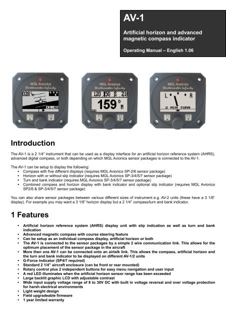
<strong>AV</strong>-1<br />
Artificial horizon and advanced<br />
magnetic compass indicator<br />
Operating <strong>Manual</strong> – English 1.06<br />
Introduction<br />
The <strong>AV</strong>-1 is a 2 1/4” instrument that can be used as a display interface for an artificial horizon reference system (AHRS),<br />
advanced digital compass, or both depending on which <strong>MGL</strong> <strong>Avionics</strong> sensor packages is connected to the <strong>AV</strong>-1.<br />
The <strong>AV</strong>-1 can be setup to display the following:<br />
• Compass with five different displays (requires <strong>MGL</strong> <strong>Avionics</strong> SP-2/6 sensor package)<br />
• Horizon with or without slip indicator (requires <strong>MGL</strong> <strong>Avionics</strong> SP-3/4/5/7 sensor package)<br />
• Turn and bank indicator (requires <strong>MGL</strong> <strong>Avionics</strong> SP-3/4/5/7 sensor package)<br />
• Combined compass and horizon display with bank indicator and optional slip indicator (requires <strong>MGL</strong> <strong>Avionics</strong><br />
SP2/6 & SP-3/4/5/7 sensor package)<br />
You can also share sensor packages between various different sizes of instrument e.g. <strong>AV</strong>-2 units (these have a 3 1/8”<br />
display). For example you may want a 3 1/8” horizon display but a 2 1/4” compass/turn and bank indicator.<br />
1 Features<br />
• Artificial horizon reference system (AHRS) display unit with slip indication as well as turn and bank<br />
indication<br />
• Advanced magnetic compass with course steering feature<br />
• Can be setup as an individual compass display, artificial horizon or both<br />
• The <strong>AV</strong>-1 is connected to the sensor packages by a simple 2 wire communication link. This allows for the<br />
optimum placement of the sensor package in the aircraft<br />
• More then one <strong>AV</strong>-1 can be connected onto an airtalk link. This allows the compass, artificial horizon and<br />
the turn and bank indicator to be displayed on different <strong>AV</strong>-1/2 units<br />
• G-Force indicator (SP4/7 required)<br />
• Standard 2 1/4” aircraft enclosure (can be front or rear mounted)<br />
• Rotary control plus 2 independent buttons for easy menu navigation and user input<br />
• A red LED illuminates when the artificial horizon sensor range has been exceeded<br />
• Large backlit graphic LCD with adjustable contrast<br />
• Wide input supply voltage range of 8 to 30V DC with built in voltage reversal and over voltage protection<br />
for harsh electrical environments<br />
• Light weight design<br />
• Field upgradeable firmware<br />
• 1 year limited warranty
<strong>AV</strong>-1 Operating <strong>Manual</strong> Page 2<br />
2 Layout<br />
Backlit graphic LCD display:<br />
Contrast and backlight can be<br />
adjusted in the menu system<br />
LED alarm:<br />
The red LED will illuminate if the<br />
artificial horizon has exceeded its<br />
maximum rate of bank, pitch or yaw<br />
RCA:<br />
RCA connects to<br />
sensor package(s)<br />
Up/F1 Button:<br />
Up button in menu system<br />
Artificial Horizon: Pitch level<br />
function<br />
Compass: Enable course<br />
steering display<br />
Harness:<br />
Harness connects to power<br />
Down/F2 Button:<br />
Down button in menu<br />
system<br />
Artificial Horizon:<br />
Fast level function<br />
Compass: Enable<br />
the reverse course<br />
display<br />
Rotary Control (Up/Down) & Enter Button:<br />
Press the rotary control during normal mode to access the menu system. Rotate anti/clockwise<br />
for up/down menu scrolling. During normal mode turning the rotary control anti/clockwise will<br />
scroll through the main displays (Artificial horizon, compass and turn and bank indicator).<br />
3 Main Display<br />
The <strong>AV</strong>-1 can be set up to show 3 different display screens. Turning the rotary control either clockwise or anti-clockwise<br />
allows you to select the operation of the <strong>AV</strong>-1 as an artificial horizon with mini compass and mini turn and bank indicator,<br />
turn and bank indicator, and a digital compass.<br />
Note: If you have purchased the artificial horizon and compass sensor packages with two or three <strong>AV</strong>-1 or <strong>AV</strong>-2 displays,<br />
it is possible to setup either of the <strong>AV</strong>-1 units to display either the artificial horizon, turn and bank indicator or the compass.<br />
This allows you to use any combination of horizon, turn and bank or compass displays. You can connect further <strong>AV</strong>-1 or<br />
<strong>AV</strong>-2 units should you require this for a dual cockpit layout. Up to six <strong>AV</strong> units can be configured to give you 2 x horizon, 2<br />
x turn and bank as well as 2 x compass displays.
<strong>AV</strong>-1 Operating <strong>Manual</strong> Page 3<br />
3.1 Artificial Horizon with Compass<br />
Magnetic (M) or true heading (T)<br />
indicator<br />
Magnetic or true heading<br />
reading (compass can be<br />
switched on or off in the menu<br />
system)<br />
10 degree pitch<br />
bars<br />
Mini turn and bank<br />
indicator (can be<br />
switched on or off in the<br />
menu system)<br />
Estimated horizon<br />
Slip indicator can be turned on or off in<br />
the menu system<br />
G-Force display<br />
Pitch level function<br />
Should your aircraft fly “nose up” or “nose down” due to trim, then you can press the F1 key to level the pitch as displayed<br />
on the horizon.<br />
3.2 Turn and Bank Indicator<br />
The slip indicator is always enabled, regardless of the slip on/off setting.<br />
Marker description<br />
Slip indicator<br />
Slip indicator<br />
A “step on the ball” slip indicator can be enabled to appear below the horizon display. The source of information for this<br />
indicator is derived from the accelerometer aligned with the pitch axis of the aircraft, i.e. the acceleration forces acting in<br />
the direction of the wings.<br />
Fast level function<br />
Press the F2 key should the horizon display be toppled (i.e. indicating incorrectly by a large amount) due to excessive<br />
maneuvering or by exceeding the maximum bank, pitch or yaw rates. This will indicate to the instrument that you are<br />
flying straight and level and that gravity tracking may be accelerated to ensure rapid realignment of the horizon.
<strong>AV</strong>-1 Operating <strong>Manual</strong> Page 4<br />
Extended range of operation<br />
Bank operates over a full 360 degree range allowing unlimited use of the horizon for aerobatics, provided that the<br />
maximum published bank, pitch and yaw rates are not exceeded. Please see the corresponding <strong>MGL</strong> sensor<br />
documentation for maximum rate specifications.<br />
Depending on conditions maximum rates may reach 180 degrees per second. No caging of the electronic gyro system is<br />
required during excessive maneuvering or aerobatics, unlike systems based on mechanical gyros. Simply correct the<br />
horizon when you are finished or let the horizon right itself which will happen during straight and level flight. The message<br />
below is displayed for 15 seconds when the range is exceeded.<br />
Message displayed when the maximum bank, pitch or yaw rates have been exceeded<br />
3.3 Digital Compass<br />
The digital compass can be displayed in 5 different ways. The way the compass is displayed can be setup in the menu<br />
system under “COMPASS SETUP”<br />
3.3.1 Numeric compass display<br />
The heading tape shows headings as numbers in degrees.<br />
Magnetic (M) or true<br />
(T) North indicator<br />
Please see the table<br />
under section 4.4 for<br />
more information<br />
about this icon<br />
3.3.2 Mixed compass display<br />
The heading tape shows headings as number in degrees except for the four major cardinal points which are shown as N,<br />
S, E and W.<br />
Magnetic (M) or true<br />
(T) North indicator<br />
Please see the table<br />
under section 4.4 for<br />
more information<br />
about this icon
<strong>AV</strong>-1 Operating <strong>Manual</strong> Page 5<br />
3.3.3 Cardinal 1 compass display<br />
The heading tape shows headings as major and minor cardinal points: N, NNE, ENE, E, ESE, SSE, S, SSW, WSW, W,<br />
WNW, and NNW.<br />
Please see the table<br />
under section 4.4 for<br />
more information<br />
about this icon<br />
Magnetic (M) or true<br />
(T) North indicator<br />
3.3.4 Cardinal 2 compass display<br />
The heading tape shows headings as major and intermediate cardinal points: N, NE, E, SE, S, SW, W and NW.<br />
Please see the table<br />
under section 4.4 for<br />
more information<br />
about this icon<br />
Magnetic (M) or true<br />
(T) North indicator<br />
3.3.5 Rose compass display<br />
The display shows a graphic representation of a vertical compass card.<br />
Please see the table<br />
under section 4.4 for<br />
more information<br />
about this icon<br />
Magnetic (M) or true<br />
(T) North indicator<br />
3.3.6 Using the course steering indicator<br />
To activate the course steering indicator, steer the required heading and then press the F1 key. The compass will display:<br />
The F1 key pressed at a heading of 89 degrees. Currently the heading equals the course<br />
to steer as shown below the heading. No course steering indicators are shown.
<strong>AV</strong>-1 Operating <strong>Manual</strong> Page 6<br />
The current heading is 85 degrees; course steering indicators show the need to steer<br />
slightly to the right to intercept the course.<br />
The current heading is 42 degrees; course steering indicators show that a large correction<br />
to the right is required to intercept the course.<br />
Each “>” or “
<strong>AV</strong>-1 Operating <strong>Manual</strong> Page 7<br />
4 Menu System<br />
Pressing the rotary control button during the normal display mode will cause the <strong>AV</strong>-1 to enter the menu system. Use the<br />
up/down keys or the rotary control to navigate through the menu system.<br />
4.1 Exit Menu<br />
Pressing the rotary control on this menu item will cause the <strong>AV</strong>-1 to exit the menu system. All<br />
changes made during navigation of the menu system will be saved in non-volatile memory on exit. If<br />
you remove power before exiting the menu the instrument will not save any changes.<br />
4.2 Display Setup<br />
Move the highlight over the “DONE” menu item and press the rotary control to return to the main<br />
menu.<br />
Select this menu option to adjust the display contrast.<br />
Select this menu option to turn the backlight on or off.<br />
4.3 Artificial Horizon Setup
<strong>AV</strong>-1 Operating <strong>Manual</strong> Page 8<br />
Move the highlight over the “DONE” menu item and press the rotary control to return to the main<br />
menu.<br />
Select if you would like to enable the slip indicator to be shown underneath the horizon display. The<br />
slip indicator operates in the same fashion as the well known “step on the ball” indicator in traditional<br />
cockpits.<br />
Note: The slip indicator is always enabled in the turn and bank indicator mode.<br />
This function allows you to set your slip indicator to exactly zero even if your aircraft tends to fly<br />
slightly wing down. The procedure is to place the aircraft in a stable, straight and level attitude<br />
during calm flight conditions and then select this function. To cancel the correction, place your<br />
sensor absolutely horizontal (use a spirit level) and select the function again.<br />
Select if you want the slip to have a high sensitivity or a low sensitivity setting.<br />
See corresponding SP-X documentation on using this feature.<br />
See corresponding SP-X documentation on using this feature.<br />
Select whether you want the turn and bank indicator’s information source to be<br />
the bank angle or actual turning information from the gyros (SP-X dependent).<br />
Select whether you want the turn and bank indicators to show a 1 min/rotation or 2 min/rotation turn.<br />
Select whether you want the mini turn and bank indicator to be shown on the horizon display screen<br />
Select if you would like to see a numeric display of bank and pitch angles superimposed on<br />
the horizon display.<br />
Select between a large or small aircraft icon on the artificial horizon display screen.<br />
Select if you would like to see the G-Force displayed on the horizon screen.
<strong>AV</strong>-1 Operating <strong>Manual</strong> Page 9<br />
4.4 Compass Setup<br />
All compass related parameters are set up here.<br />
Move the highlight over the “DONE” menu item and press the rotary control to return to the main<br />
menu<br />
Select whether you want the mini compass to be shown on the horizon display screen.<br />
Select the desired compass display mode as described in section 3.4 above<br />
Select whether you would like the instrument to display magnetic or true heading. If you select true<br />
heading, you need to enter the correct magnetic variation for your location. You can find your local<br />
variation on aeronautical or maritime charts. The heading displays will be augmented with °M or °T<br />
depending on the mode you have selected.<br />
Enter the magnetic variation of your location. This is only used if you would like the instrument to<br />
display true heading. True heading is the heading relative to the geographic North Pole. Magnetic<br />
heading is the heading relative to the magnetic North Pole. Variation is expressed in degrees east or<br />
west. Please note that should you move a long distance, you may have to update the variation<br />
setting. This setting may be ignored if you only use the magnetic heading display option.<br />
Select the mode you would like your compass to operate under:<br />
2D: This mode selects a two axis compass system. This has no tilt compensation.<br />
3D A: This mode selects a three axis compass system. Tilt compensation by means of gravity vectoring via<br />
accelerometers.<br />
3D G: This mode selects a three axis compass system. Tilt compensation by means of information supplied by an artificial<br />
horizon.<br />
SP-1 can only be used in 2D mode.<br />
SP-2/6 can be used in modes 2D or 3D A. 3D G is available if an external artificial horizon is connected.<br />
SP-3hc can be used with any of the above modes.<br />
Each mode has advantages and disadvantages over other modes. Briefly, these are outlined in the table below:<br />
2D<br />
Mode Advantages Disadvantages<br />
Most accurate as long as the compass remains level. Not affected<br />
by turns or acceleration provided compass remains level during<br />
turns.<br />
Large heading errors when compass<br />
is tilted.<br />
The magnitude of these errors is<br />
dependent on the heading, type of tilt<br />
(pitch and/or bank) as well as location<br />
on Earth.<br />
3D-A<br />
Self-contained tilt compensated compass. Will compensate for most<br />
tilt errors up to 60 degrees of tilt.<br />
Cannot correctly compensate for tilt<br />
during any form of turn due to<br />
centrifugal forces acting on the
<strong>AV</strong>-1 Operating <strong>Manual</strong> Page 10<br />
3D-G<br />
Can provide for accurate heading even during turns as tilt<br />
compensation is based on gyro derived horizon.<br />
accelerometers.<br />
Can show very large errors if the<br />
horizon information is invalid which<br />
could have a number of causes such<br />
as exceeding operational limitations of<br />
the horizon system.<br />
Using the deviation calibration feature<br />
When you install your compass sensor package, it may be surrounded by several items or materials that in some way<br />
change the strength and/or direction of the earth magnetic field that your sensors are measuring. If left unattended, this<br />
may contribute to considerable errors in the heading as indicated by your instrument.<br />
Due to the magnetic sensor not being based on a magnetic item (such as a magnetic needle) as in a normal compass,<br />
the effect of deviation is lessened a little. This is because the needle in a magnetic compass will be attracted by iron, even<br />
if the offending iron has no effect on the magnetic field (i.e. does not change the field direction or strength in a<br />
hypothetical case).<br />
Deviation needs to be corrected if you intend using the compass for navigational purposes. The procedure for this is<br />
traditionally called a “compass swing”. Often, two small magnets are placed close to the compass in an effort to correct<br />
some of the larger errors. Smaller, remaining errors are then noted on a “deviation chart” and this is placed next to the<br />
compass for future reference.<br />
With the SP-1, 2,3 and 6, a very simple method can be used to correct for most of the deviation that may be present in<br />
your aircraft or vehicle. However, before you start, ensure that the sensor package is installed as far away as possible<br />
from any of the following:<br />
• Ferro magnetic materials such as iron, many steels and soft magnetic materials such as ferrites. Any magnets<br />
must be located as far away as possible from the sensor package. This includes electromagnets as used in<br />
solenoids, electrical motors and relays.<br />
• Cables containing large electrical currents. DC currents will cause magnetic fields around the cables which will<br />
lead to deviation. AC currents cause fluctuating magnetic fields that may reduce your compass resolution.<br />
• Be aware that some lower grades of stainless steel may be ferro magnetic.<br />
If in any doubt, use a small magnet to test any metals surrounding the sensor package. We recommend mounting the<br />
sensor package using glued on strips of velcro material. This allows for easy alignment of the sensor package horizontal<br />
to the earth’s magnetic field.<br />
Never perform the deviation compensation procedure or a compass swing if your aircraft is placed on a reinforced<br />
concrete apron or tarmac. The steel that may have been used to reinforce may have a very significant effect on the<br />
strength and direction of the magnetic field at your location.<br />
To start the deviation compensation procedure, enter the menu and select “SET DEVIATION”.<br />
Place your aircraft in flight attitude. For example, if you own a tail dragger, raise the tail.<br />
Some tricycle gear aircraft may need to raise the nose gear slightly. The object is to<br />
place the sensor package as close to horizontal attitude relative to the earth’s surface as<br />
possible.<br />
Proceed as instructed and turn the aircraft through a full 360 degrees at least once.<br />
Allow this procedure to take some time, perhaps a minute. You can proceed to turn your<br />
aircraft though two or more turns, however you need to fully complete at least one full<br />
turn.<br />
If you like, you can press the F1 key during this procedure to see the actual numeric data obtained from the<br />
magnetometers. You will see the instrument tracking minimum and maximum values for each sensor and you can see the<br />
current values.
<strong>AV</strong>-1 Operating <strong>Manual</strong> Page 11<br />
Once you have completed your turn(s), press the F2 key again to inform the instrument that you have finished. Your<br />
instrument will at this point calculate the best possible fit of the sensor data to a 360 degree arc taking the relative<br />
strengths and offsets of the magnetic field into account. This procedure can result in remarkably good overall<br />
performance of your compass.<br />
Please note: After this procedure has been completed, you may have to verify the compass performance by performing a<br />
normal compass swing. Should any deviation remain, you need to note this on a deviation card and place this card next to<br />
the compass. This may be a legally required procedure in your country for your aircraft class. Please check your relevant<br />
regulations. Deviation compensation and compass swing may need to be repeated from time to time as the magnetic<br />
properties of metals in your aircraft may change over time.<br />
Clears any previous deviation compensation and returns the instrument to factory calibration<br />
The purpose of this function is to cancel out the remaining errors on the main<br />
cardinal headings after a deviation compensation calibration has been done.<br />
Align your aircraft exactly on a North/South heading, pointing North. Use another compass outside of the aircraft to<br />
ensure that you are aligned exactly on the North/South axis. Select the “SET NORTH” function.<br />
Repeat the above calibration for the South, East and West cardinal headings.<br />
This function, if used properly can lessen any remaining deviation that may be present after you have performed the<br />
prescribed compass swing. If you cannot find a successful setting using both methods, examine your installation location<br />
more closely. Perhaps you have an interfering metal part nearby. You may need to choose a different location to mount<br />
the compass sensor.<br />
Note: In difficult circumstances it may not be possible to find a location for the sensor inside the fuselage of your aircraft.<br />
This may be particularly true for aircraft based on tubular steel frames. In this case you need to locate the compass<br />
sensor inside the wing (perhaps in a wing-tip).<br />
5 Operating the Artificial horizon<br />
The horizon is designed to erect itself rapidly whenever possible. This means that during ordinary flight you do not interact<br />
with the unit. The horizon may loose accuracy. This may have several causes:<br />
• You have exceeded the maximum allowable turn rate on one or more axis.<br />
• Continuous maneuvering without giving the unit a chance to correct for errors. In this case gyro drift will eventually<br />
cause a noticeable error in the horizon.<br />
• The IMU is subject to vibration from the engine. Often you will find this will have an effect only at very specific<br />
engine RPM.<br />
• The IMU is subject to rapid temperature changes or is operating outside of the recommended temperature range<br />
(consider re-setting offsets in this case).<br />
• The IMU bump factor is set incorrect for your aircraft. (SP-X dependent). Try a different setting.<br />
In order to correct the horizon display, you need to fly straight and level. The horizon will correct itself in this case given<br />
some time (about 15 seconds to a minute depending on severity of the error and your “slew” setting). You can also press<br />
the F2 key to force an immediate correction. You must fly straight and level for this to work correctly.<br />
Power and trim changes will affect the pitch display of the horizon. You can set the horizon to zero by pressing the F1 key.<br />
To get back to the real horizon, press the F1 key again.
<strong>AV</strong>-1 Operating <strong>Manual</strong> Page 12<br />
6 Using the IMU in flight<br />
The pilot in command of the aircraft has to be aware of the following:<br />
The SP-X sensor packages are not certified by the FAA or any other agency for use during IFR (instrument flight<br />
rules). This implies that any such flight that uses the SP-X IMU as reference for either heading, turn and bank or<br />
horizon is illegal.<br />
7 Loading Factory default settings<br />
Pressing and holding the F1 and F2 keys simultaneously on power up will cause the <strong>AV</strong>-1 to load the factory default<br />
settings. The following screen will be displayed.<br />
8 Cleaning<br />
The unit should not be cleaned with any abrasive substances. The screen is very sensitive to certain cleaning materials<br />
and should only be cleaned using a clean, damp cloth.<br />
Warning: The <strong>AV</strong>-1 is not waterproof. Serious damage could occur if the unit is exposed to water<br />
and/or spray jets.<br />
9 Specifications<br />
Operating Temperature Range<br />
Storage Temperature Range<br />
Humidity<br />
Power Supply<br />
Current Consumption<br />
Display<br />
Dimensions<br />
Enclosure<br />
Weight<br />
Non-volatile memory storage<br />
Airtalk protocol<br />
<strong>MGL</strong> <strong>Avionics</strong> sensor packages<br />
-10ºC to 50ºC (14ºF to 122ºF)<br />
-20ºC to 80ºC (-4ºF to 176ºF)<br />
<strong>AV</strong>-1 Operating <strong>Manual</strong> Page 13<br />
10 Installation<br />
Note: Please see corresponding sensor package manuals for more information about the<br />
installation and use of the artificial horizon and compass.<br />
10.1 Connection Diagram<br />
The use of an external 1A fuse is recommended. Connect the supply terminals to your aircraft’s power supply. The <strong>AV</strong>-1<br />
can be used on both 12V and 24V without the use of any pre-regulators. Ensure that the supply voltage will not drop<br />
below 8V during operation as this may result in incorrect displays. Should you be installing more than one <strong>AV</strong>-1 unit, use<br />
standard RCA splitter cables to create more nodes on the airtalk cable.<br />
Using RCA cables<br />
The airtalk link uses easily available RCA video or audio cables. You can connect the SP-X sensor package to up to six<br />
<strong>AV</strong>-1/2 units. You can use ordinary RCA cables and splitter cables for this. You can also make up your own cables.<br />
However, use only suitable, shielded cable. Thin 75 ohm video cable are most suitable. The cable can be extended to a<br />
length of up to six meters, allowing convenient placement of the SP-X sensor package. Slightly bend the outside tabs on<br />
the RCA connectors inwards to ensure a tight fit of the connectors. For critical applications, use very high quality<br />
connectors and secure the connectors on cables so they cannot separate by accident.
<strong>AV</strong>-1 Operating <strong>Manual</strong> Page 14<br />
SP5 Attitude Sensor package.<br />
10.2 DB9 Cable connections<br />
DB 9 Pin Color Function<br />
1 Black Ground<br />
4 RCA (Inner cable) Airtalk communication link<br />
6 Red 8-30Vdc power<br />
11 Warranty<br />
This product carries a warranty for a period of one year from date of purchase against faulty workmanship or defective<br />
materials, provided there is no evidence that the unit has been mishandled or misused. Warranty is limited to the<br />
replacement of faulty components and includes the cost of labor. Shipping costs are for the account of the purchaser.<br />
Note: Product warranty excludes damages caused by unprotected, unsuitable or incorrectly wired<br />
electrical supplies and/or sensors, and damage caused by inductive loads.<br />
12 Disclaimer<br />
Operation of this instrument is the sole responsibility of the purchaser of the unit. The user must make themselves familiar<br />
with the operation of this instrument and the effect of any possible failure or malfunction.<br />
This instrument is not certified by the FAA. Fitting of this instrument to certified aircraft is subject to the rules and<br />
conditions pertaining to such in your country. Please check with your local aviation authorities if in doubt. This instrument<br />
is intended for ultralight, microlight, home built and experimental aircraft. Operation of this instrument is the sole<br />
responsibility of the pilot in command (PIC) of the aircraft. This person must be proficient and carry a valid and relevant<br />
pilot’s license. This person has to make themselves familiar with the operation of this instrument and the effect of any<br />
possible failure or malfunction. Under no circumstances does the manufacturer condone usage of this instrument for IFR<br />
flights.<br />
The manufacturer reserves the right to alter any specification without notice.
<strong>AV</strong>-1 Operating <strong>Manual</strong> Page 15<br />
Other instruments in the Stratomaster Infinity series<br />
ALT-1 Precision encoding altimeter and vertical speed indicator<br />
ALT-2 Precision encoding altimeter and vertical speed indicator with a serial RS232<br />
transponder output<br />
ASI-1 Airspeed indicator (ASI) with automatic flight log<br />
ASX-1 Encoding aviation altimeter with serial output and airspeed indicator (ASI)<br />
<strong>AV</strong>-1 Artificial horizon and magnetic compass indicator<br />
BAT-1 Battery voltage and current monitor<br />
E-3 Universal engine monitor<br />
FF-1 Fuel Computer (single or dual fuel tanks)<br />
GF-1 +-10G tilt compensated dual range G-force meter<br />
MAP-1 Manifold pressure and RPM Indicator<br />
RV-1 Universal engine RPM and rotor RPM Indicator<br />
RV-2 Universal turbine RPM / RPM factor display<br />
RTC-2 Aviation real time clock (RTC) and outside air temperature (OAT) display<br />
TC-1 4-Channel thermocouple indicator<br />
TP-1 Universal temperature and pressure gauge