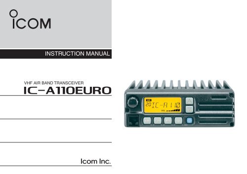
IC-A110 EURO instruction maual - AEROSHOP.eu
IC-A110 EURO instruction maual - AEROSHOP.eu
IC-A110 EURO instruction maual - AEROSHOP.eu

Create successful ePaper yourself
Turn your PDF publications into a flip-book with our unique Google optimized e-Paper software.
INSTRUCTION MANUAL<br />
VHF AIR BAND TRANSCEIVER<br />
i<strong>A110</strong><strong>EURO</strong>
i<br />
FOREWORD<br />
READ ALL INSTRUCTIONS carefully and completely<br />
before using the transceiver.<br />
SAVE THIS INSTRUCTION MANUAL — This <strong>instruction</strong><br />
manual contains important operating <strong>instruction</strong>s<br />
for the <strong>IC</strong>-<strong>A110</strong><strong>EURO</strong>.<br />
EXPL<strong>IC</strong>IT DEFINITIONS<br />
The explicit definitions below apply to this <strong>instruction</strong> manual.<br />
WORD<br />
RWARNING!<br />
CAUTION<br />
NOTE<br />
DEFINITION<br />
Personal injury, fire hazard or electric shock<br />
may occur.<br />
Equipment damage may occur.<br />
If disregarded, inconvenience only. No risk<br />
of personal injury, fire or electric shock.<br />
Icom, Icom Inc. and Icom logo are registered trademarks of Icom Incorporated<br />
(Japan) in Japan, the United States, the United Kingdom,<br />
Germany, France, Spain, Russia and/or other countries.<br />
CAUTIONS<br />
R WARNING! NEVER operate the transceiver with a<br />
headset or other audio accessories at high volume levels.<br />
Hearing experts advise against continuous high volume operation.<br />
If you experience a ringing in your ears, reduce the<br />
volume level or discontinue use.<br />
NEVER connect the transceiver to an AC outlet or to a<br />
power source of more than 32 V DC. Such a connection will<br />
damage the transceiver.<br />
NEVER connect the transceiver to a power source that is<br />
DC fused at more than 5 A. Accidental reverse connection<br />
will be protected by this fuse, higher fuse values will not give<br />
any protection against such accidents and the transceiver<br />
will be ruined.<br />
DO NOT operate the transceiver near unshielded electrical<br />
blasting caps or in an explosive atmosphere.<br />
DO NOT connect the transceiver to a power source using<br />
reverse polarity. This connection will not only blow fuses but<br />
also may damage the transceiver.<br />
DO NOT place unit in a non-secure place to avoid inadvertent<br />
use by children.
TABLE OF CONTENTS<br />
DO NOT push [PTT] when not actually desiring to transmit.<br />
DO NOT use or place the transceiver in direct sunlight or<br />
in areas with temperatures below –30°C (–22°F) or above<br />
+60°C (+140°F).<br />
DO NOT place the transceiver in excessively dusty environments.<br />
DO NOT place the transceiver against walls. This will obstruct<br />
heat dissipation.<br />
DO NOT use harsh solvents such as benzine or alcohol<br />
to clean the transceiver, as they can damage the transceiver’s<br />
surfaces.<br />
BE CAREFUL! The transceiver will become hot when<br />
operating continuously for long periods of time.<br />
FOREWORD ........................................................................................... i<br />
EXPL<strong>IC</strong>IT DEFINITIONS ........................................................................ i<br />
CAUTIONS .............................................................................................. i<br />
TABLE OF CONTENTS .......................................................................... ii<br />
1 PANEL DESCRIPTION .............................................................. 1 – 3<br />
■ Panel description ................................................................................. 1<br />
■ Function display ................................................................................... 3<br />
2 BAS<strong>IC</strong> OPERATION .................................................................. 4 – 5<br />
■ Power ON ............................................................................................ 4<br />
■ Channel selection................................................................................. 4<br />
■ Squelch function................................................................................... 5<br />
■ Side tone function................................................................................. 5<br />
■ LCD backlight control............................................................................ 5<br />
■ Dial select function................................................................................ 5<br />
3 SCAN OPERATION ................................................................... 6 – 7<br />
■ Scan operation ..................................................................................... 6<br />
■ ON-Hook scan ..................................................................................... 7<br />
■ Dualwatch ............................................................................................ 7<br />
4 MEMORY PROGRAMMING ...................................................... 8 – 9<br />
■ Programming a memory channel.......................................................... 8<br />
■ Memory names..................................................................................... 9<br />
5 OTHER FUNCTIONS ............................................................. 10 – 11<br />
■ Initial Set mode .................................................................................. 10<br />
6 CONNECTION AND INSTALLATION ................................... 12 – 13<br />
■ Rear panel and connections .............................................................. 12<br />
■ Mounting ............................................................................................ 13<br />
■ Supplied accessories.......................................................................... 13<br />
7 CLONING ...................................................................................... 14<br />
8 SPECIF<strong>IC</strong>ATIONS ........................................................... 15 – 17<br />
9 OPC-871 HEADSET ADAPTER/OTHER OPTIONS....... 18 – 19<br />
■ OPC-871 Headset adapter................................................................. 18<br />
■ Other Options..................................................................................... 19<br />
ii
1 PANEL DESCRIPTION<br />
■ Panel description<br />
q w e r<br />
V/M SCAN PRI SQL<br />
!0 o i u y t<br />
q TUNING [DIAL] [TS](DIAL)<br />
➥ Changes the operating frequency; memory channel in<br />
the Memory mode; set mode contents in the Set mode,<br />
etc.<br />
➥ Push to toggle the dimmer control OFF, Low or High.<br />
➥ Hold down for 1 second to select the Tuning Step<br />
[TS]; 1 MHz or 10 kHz are selectable. (p. 5)<br />
w FUNCTION DISPLAY (p. 3)<br />
Displays the operating frequency, memory channel name,<br />
etc.<br />
e VOLUME UP [Y] DOWN [Z] KEY<br />
Adjusts the audio output level.<br />
r LOUD SPEAKER<br />
Front mounted loud speaker.<br />
t POWER SWITCH [POWER]<br />
Hold down 0.5 seconds to turn the power ON and OFF.<br />
• At Power ON, the Initial Set mode (p. 10) or the Cloning mode<br />
(p. 14) can optionally be selected.<br />
1
PANEL DESCRIPTION<br />
1<br />
y SQL SWITCH [SQL]<br />
➥ Push to turn ON the squelch adjust mode. (p. 6)<br />
➥ Hold down this switch for 1 second to turn the both internal<br />
and external speaker output ON or OFF. (p. 4)<br />
u PRIORITY SWITCH [PRI]<br />
➥ Push to select the priority channel. (p. 11)<br />
• “Pr” appears on the display.<br />
i SCAN SWITCH [SCAN]<br />
➥ Starts and stops the scan function:<br />
• VFO mode: VFO scan function. (p. 6)<br />
• Memory mode: Memory channel scan function. (p. 6)<br />
➥ Hold down this switch for 5 seconds to set the displayed<br />
channel as a memory lock-out channel. (p. 8)<br />
• “LOCK OUT” appears on the display.<br />
o VFO/MEMORY SWITCH [V/M] [MW](V/M)<br />
➥ Push to toggle between the VFO mode and the Memory<br />
mode. (p. 4)<br />
• “X” and memory channel number appear when the Memory<br />
mode is selected.<br />
• The transceiver has 99 memory channels.<br />
➥When the VFO mode is selected;<br />
• Hold down this switch for 5 seconds to enter the VFO frequency<br />
into memory channel. (p. 8)<br />
➥When the Memory mode is selected;<br />
• Hold down this switch for 5 seconds to turn ON the “Memory<br />
name write mode.”<br />
!0 M<strong>IC</strong>ROPHONE CONNECTOR<br />
Connects to the supplied microphone or optional.<br />
NEVER connect other microphones. The pin assignments<br />
may be different and the transceiver may be damaged.<br />
M<strong>IC</strong>ROPHONE<br />
The supplied microphone has a PTT switch and a cradle.<br />
The following functions are available when the microphone<br />
is taken off the hook or put back on the hook:<br />
➥ Automatic scan starts when the microphone is put ON Hook.<br />
(p. 7)<br />
➥ Automatic scan stops when the microphone is taken OFF Hook.<br />
(p. 7)<br />
NOTE: Optional functions vary with transceiver version. In<br />
this manual, optional functions are indicated by an<br />
“ ” Icon.<br />
Please contact your dealer for details.<br />
2
1 PANEL DESCRIPTION<br />
■ Function display<br />
t TX IND<strong>IC</strong>ATOR (p. 5)<br />
Appears while transmitting.<br />
!1<br />
q w e r t<br />
y<br />
y FREQUENCY DISPLAY (p. 11)<br />
➥Shows the operating frequency.<br />
➥Shows the channel name when the memory name<br />
function is selected. (p. 10)<br />
u VOLUME LEVEL IND<strong>IC</strong>ATORS<br />
➥ Shows the AF volume level (while receiving).<br />
o i u<br />
i SET MODE IND<strong>IC</strong>ATOR<br />
➥ Appears when the Initial Set mode is selected. (p. 12)<br />
q MEMORY MODE IND<strong>IC</strong>ATOR (p. 5)<br />
Appears when the Memory mode is selected.<br />
w DUALWATCH IND<strong>IC</strong>ATOR (p. 7)<br />
Appears when the dualwatch function is activated.<br />
e SCAN IND<strong>IC</strong>ATOR (p. 8)<br />
Appears when the scan function is selected.<br />
r BUSY IND<strong>IC</strong>ATOR (p. 6)<br />
“BUSY” appears when receiving a signal or when the<br />
squelch is open. (p. 6)<br />
!0 LOCK OUT IND<strong>IC</strong>ATOR<br />
➥ Appears when the channel is set as a ‘LOCK OUT’<br />
channel. (p. 10)<br />
!1 MEMORY CHANNEL IND<strong>IC</strong>ATOR<br />
➥ Indicates the selected memory channel number<br />
➥ ‘Pr’ appears when the priority channel is selected.<br />
*NOTE: The VFO/memory switch [V/M] and the memory<br />
write switch [MW](V/M) functions may not be available, depending<br />
on version.<br />
3
BAS<strong>IC</strong> OPERATION<br />
2<br />
■ Power ON<br />
q Push [POWER] to turn ON the power.<br />
w Operate the transceiver as described in the following sections.<br />
e Select the desired memory channel (or VFO frequency)<br />
with the [V/M] keys.<br />
• When receiving a signal, appears and audio is heard<br />
from the speaker.<br />
• Further adjustment of the audio level may be necessary at this<br />
point.<br />
• Push [SQL] to adjust the squelch level. (p. 6)<br />
• Hold down [TS](DIAL) for 1 second to select the tuning step.<br />
1MHz or 10 kHz are selectable. (p. 7)<br />
r Hold down [PTT] to transmit, then speak into the microphone<br />
at your normal voice level.<br />
• Transmit indicator<br />
t Release [PTT] to receive.<br />
lights.<br />
■ Channel selection<br />
ï VFO/Memory selection<br />
Push [V/M] to select the Memory<br />
mode or the VFO mode.<br />
➥ Rotate [DIAL] to select a desired<br />
frequency or channel.<br />
ï External speaker output control<br />
External speaker output can be turned OFF, if desired.<br />
q Hold down [SQL] for 1 second.<br />
w Rotate [DIAL] to select “SP OFF”.<br />
e Push [SQL] to return to the previous mode.<br />
NOTE: This function is available<br />
both internal and external<br />
speakers.<br />
4
2 BAS<strong>IC</strong> OPERATION<br />
5<br />
■ Squelch function<br />
The transceiver has a noise squelch circuit to mute undesired<br />
noise while receiving no signals.<br />
D Setting the squelch level<br />
q Push [SQL] to turn ON the level adjusting mode.<br />
w Rotate [DIAL] to select the squelch level.<br />
• ‘SQ 01’ is loose squelch and ‘SQ 25’ is tight squelch. (Initial<br />
level is ‘SQ 01’)<br />
• ‘SQ 01’ indicates that the squelch circuit is turned off.<br />
• “ ” appears on the display.<br />
e Push [SQL] to return to regular operation.<br />
■ Side tone function<br />
When using an optional headset, such as those from the<br />
David Clark Co. using the OPC-871 HEAD SET ADAPTER, the<br />
transceiver outputs your transmitted voice to the headset for<br />
monitoring. (p. 17)<br />
■ LCD backlight control<br />
The backlight of the LCD can be set to OFF, Low or High.<br />
➥ Push [DIAL] to toggle the backlight control; OFF, Low or<br />
High are selectable.<br />
■ Dial select function<br />
Use the dial select function to adjust the tuning step of the<br />
[DIAL] keys. Use 1 MHz tuning when you want to change the<br />
frequency in large increments; use regular tuning (25 kHz or<br />
8.33 kHz) when you want to change the frequency in<br />
smaller increments.<br />
q Push [V/M] to select the<br />
VFO mode.<br />
w Hold down [TS](DIAL) for 1<br />
second to select the desired<br />
tuning increment.<br />
• 1 MHz tuning or regular<br />
tuning steps can be selected.<br />
(See the diagrams<br />
to the right.)<br />
e Hold down [TS](DIAL) for 1<br />
second to return to normal<br />
operation.<br />
1 MHz tuning selected<br />
Regular tuning selected<br />
NOTE: Large tuning steps should be used only when you<br />
want to change the frequency in large increments. Please<br />
select regular tuning steps for normal operation.
SCAN OPERATION<br />
3<br />
■ Scan operation<br />
q Push [V/M] to select the Memory mode or the VFO mode,<br />
if necessary.<br />
• “ ” appears when in the Memory mode.<br />
w Make sure the squelch level is set to the threshold point.<br />
• Set the squelch level (01 to 25) where the noise is just muted.<br />
e Push [SCAN] to start the scan.<br />
• To change the scan direction, turn [DIAL].<br />
• “SCAN (or P SCAN)“ flashes while scanning.<br />
r Push [SCAN] again to stop the scan.<br />
NOTE: Normal scan or Priority scan is pre-programmed<br />
by cloning. Please ask your dealer or system operator for<br />
details.<br />
• VFO scan<br />
R e p e a t e d l y s c a n s a l l<br />
frequencies over the entire<br />
band. Scan step is minimum<br />
channel spacing. (e.g. 25 kHz or<br />
8.33 kHz)<br />
ï PRIORITY SCAN<br />
• Priority memory scan<br />
While scanning in the Memory<br />
mode, priority watch checks for<br />
a s i g n a l o n t h e s e l e c t e d<br />
priority channel every 250<br />
msec. and skips the lockout<br />
channel(s).<br />
lowest<br />
frequency<br />
Start<br />
250 msec.<br />
Priority<br />
ch<br />
Scan<br />
Jump<br />
SKIP<br />
250 msec.<br />
Mch 1<br />
Mch 2*<br />
Mch 3<br />
Mch 99<br />
highest<br />
frequency<br />
*: Lockout ch<br />
ï NORMAL SCAN<br />
• Memory lock scan<br />
Repeatedly scans memory<br />
channels except skip (lockout)<br />
channels.<br />
Mch 1<br />
Mch 2* SKIP<br />
Mch 3<br />
Mch 99<br />
250 msec. *: Lockout ch<br />
6
3 SCAN OPERATION<br />
■ ON–Hook scan<br />
An ON–Hook scan (Hanger scan) stops when taking the microphone<br />
off its hanger (OFF–Hook) and resumes when<br />
putting it back on the hanger (ON–Hook).<br />
➥ Push [SCAN] to start scanning.<br />
• When a signal is received, the scan pauses until the signal disappears.<br />
• The scan resumes 2 seconds after the signal disappears, unless<br />
you pushed [PTT] and transmitted.<br />
• Take the microphone off the hanger to stop the scan.<br />
• Put the microphone back on the hanger to resume scanning.<br />
When you take the microphone OFF Hook during the scan<br />
operation.<br />
• In VFO scan;<br />
the scan stops on the last frequency that was scanned.<br />
• In memory scan;<br />
the scan stops on the last memory channel that was<br />
scanned.<br />
• In priority memory scan;<br />
the scan stops on the priority channel.<br />
■ Dualwatch<br />
Dualwatch monitors the priority channel while you are<br />
receiving another channel (VFO or memory channel).<br />
• If a signal is received on the<br />
priority channel, dualwatch<br />
pauses on the priority channel<br />
until the signal disappears.<br />
• To transmit on the selected<br />
channel during dualwatch,<br />
hold down [PTT].<br />
See page 11 for details of the priority channel setting.<br />
ï Operation<br />
250 msec.<br />
Priority<br />
channel<br />
5 sec.<br />
VFO<br />
frequency<br />
or<br />
memory<br />
channel<br />
q Select the desired operating channel (VFO or Memory<br />
channel).<br />
w Hold down [PRI] for 1 second to start dualwatch.<br />
‘P’ blinks during dualwatch.<br />
e To cancel dualwatch, push [PRI] again.<br />
NOTE: Be sure to connect the supplied microphone<br />
hanger to the vehicle’s ground for ON and OFF Hook microphone<br />
functions. (p. 12)<br />
7
MEMORY PROGRAMMING<br />
4<br />
■ Programming a memory channel<br />
The transceiver has 99 memory channels for storage of<br />
often-used frequencies.<br />
q Push [V/M] to select the VFO<br />
mode, if necessary.<br />
w Rotate [DIAL] to select the<br />
desired frequency.<br />
• Push [TS](DIAL) one or more<br />
times to use the dial select<br />
function, if desired.<br />
e Hold down [MW](V/M) for 5<br />
seconds to enter the memory<br />
programming mode.<br />
MR<br />
• “ ” and the memory channel<br />
number appear.<br />
r Rotate [DIAL] to select the<br />
MR<br />
desired memory channel<br />
number.<br />
t Hold down [MW](V/M) for 1<br />
second to program the information<br />
into the channel and<br />
return to the VFO mode.<br />
• To cancel the memory information,<br />
hold down [SQL] for 1<br />
second.<br />
D Setting lockout channels<br />
In order to speed up the scan periods, you can set memory<br />
channels you don’t wish to be scanned as lockout channels.<br />
q Push [V/M] to select the Memory mode, if necessary.<br />
• “ ” appears.<br />
w Rotate [DIAL] to select a memory channel to set as a<br />
lockout channel.<br />
e Hold down [SCAN] for 5 seconds<br />
to toggle the lockout<br />
setting ON or OFF.<br />
• “LOCK OUT” appears when<br />
the channel is set as a lockout Memory channel 8 is set<br />
channel.<br />
as the lockout channel.<br />
NOTE: The VFO/memory switch [V/M] and the memory<br />
write switch [MW] functions may not be available, depending<br />
on version.<br />
8
4 MEMORY PROGRAMMING<br />
■ Memory names<br />
ï Programming memory names<br />
q Select the memory channel to be programmed:<br />
➥ Push [V/M] to select the Memory mode.<br />
➥ Rotate [DIAL] to select the memory channel.<br />
w Hold down [MW](V/M) for 5 seconds to enter memory<br />
name writing mode.<br />
• The first digit blinks.<br />
e Repeatedly rotates [DIAL] to select the desired character.<br />
• To erase a character, overwrite with a space (displayed as _).<br />
• To move the cursor forwards or backwards, push [Y] or [Z].<br />
• Hold down [SQL] for 2 seconds to erase all characters.<br />
r Hold down [MW](V/M) for 2 seconds to input the entered<br />
name.<br />
• The character stops blinking.<br />
• Memory channels can be programmed with names of up to 7<br />
characters in length.<br />
• When no name is programmed, the display shows the operating<br />
frequency.<br />
NOTE: Push [PTT] to cancel the memory name programming.<br />
• The following characters can be used in names:<br />
➥ 0 to 9, A to Z (capitals), (space), $, %, ’, (, ), ✽, +, “<br />
, ”, –, /, , , @, [, \, ], ^, _ and `.<br />
[EXAMPLE]: Setting the name to “ TOWER 2”<br />
V/M for 5 sec. + or<br />
V/M for 1 sec.<br />
9
OTHER FUNCTIONS<br />
5<br />
■ Initial Set mode<br />
The Initial Set mode is accessed at Power ON, and allows<br />
you to set seldom-changed settings. In this way you can the<br />
“customize” the transceiver operations to suit your<br />
preferences and operating style.<br />
D Entering Initial Set mode<br />
q While holding down [V/M] + [TS](DIAL), push [POWER] to<br />
turn ON the power.<br />
• The transceiver enters the Initial Set mode and “MN”, “BP”, “ST”<br />
or “PR” (p. 11) appears on the display.<br />
w Push [TS](DIAL) to select the<br />
desired item as described<br />
below and to the right.<br />
e Rotate [DIAL] to select the desired<br />
option or setting.<br />
r Push [SCAN] to exit the Initial<br />
Set mode and return to the<br />
previous operating mode.<br />
D Beep tones ON/OFF<br />
Confirmation beep tones normally<br />
sound when you push a key.<br />
These can be turned ON or OFF,<br />
as you prefer.<br />
D Side tones ON/OFF<br />
When using an optional headset<br />
such as those from the David<br />
Clark Co. using an adapter, the<br />
transceiver outputs your transmitted<br />
voice to the headset for monitoring.<br />
• Optional OPC-871 H E A D S E T<br />
ADAPTER is required.<br />
D Memory names<br />
This item allows you to display a memory name instead of<br />
the frequency.<br />
• When a memory channel has not been programmed with a name,<br />
the frequency appears instead.<br />
10
5<br />
OTHER FUNCTION<br />
D Priority channel<br />
The priority channel is used to store your most often-used<br />
channel for quick recall. In addition, the priority channel is<br />
monitored during priority scan modes. The default setting for<br />
the priority channel will differ, depending on pre-programming.<br />
➥ Push [PRI] to toggle the priority<br />
channel mode or previous<br />
mode.<br />
• Setting the priority channel<br />
q While holding down [V/M] and [TS](DIAL), push [POWER]<br />
to turn ON the power.<br />
• The transceiver enters the<br />
Initial Set mode.<br />
w Push [TS](DIAL) to select<br />
the priority channel Set<br />
mode.<br />
e Rotate [DIAL] to select the<br />
desired channel number<br />
as a priority channel or<br />
OFF.<br />
r Hold down [POWER] to<br />
turn OFF the power.<br />
NEVER select the blank memory channel as the priority<br />
channel. In such a case the priority function is automatically<br />
set to the OFF position.<br />
11
CONNECTION AND INSTALLATION<br />
6<br />
■ Rear panel and connections<br />
w<br />
r External speaker jack<br />
q<br />
Antenna<br />
t<br />
OPC-871 HEADSET<br />
ADAPTER (Option)<br />
e<br />
Supplied DC<br />
power cable<br />
black: _<br />
red: +<br />
12 V or 24 V<br />
Battery<br />
q Connects to an antenna<br />
Ask your dealer about antenna selection and best installation<br />
location. (Standard 50 Ω antenna with an SWR<br />
6 CONNECTION AND INSTALLATION<br />
■ Mounting<br />
Flat washer<br />
Spring washer<br />
■ Supplied accessories<br />
q<br />
w<br />
e<br />
r<br />
13<br />
When using<br />
self-tapping screws<br />
The universal mounting bracket supplied with your transceiver<br />
allows overhead or dashboard mounting. Please read<br />
the following <strong>instruction</strong>s carefully.<br />
• Mount the transceiver securely with the 4 supplied<br />
screws (M5 × 20) to a surface which is more than 10<br />
mm thick and can support more than 5 kg.<br />
• Mount the transceiver so that the face of the transceiver<br />
is at 90˚ to your line of sight when operating.<br />
IMPORTANT!<br />
Detailed installation notes for Icom mobile transceivers to<br />
be fitted into vehicles are available. Contact your Icom<br />
dealer or distributor.<br />
t<br />
q Microphone ................................................................................. 1<br />
w Microphone hanger and screw set ........................................ 1 set<br />
e Microphone cable ........................................................................ 1<br />
r DC power cable (OPC-1091) ...................................................... 1<br />
t Mounting bracket......................................................................... 1<br />
y Bracket bolts ............................................................................... 4<br />
u Mounting screws (M5 × 12) ......................................................... 4<br />
i Self-tapping screws (M5 × 20) .................................................... 4<br />
o Flat washers ................................................................................ 4<br />
!0 Spring washers ........................................................................... 4<br />
!1 Nuts ............................................................................................. 4<br />
!2 Fuses (10 A) ............................................................................... 2<br />
y<br />
u<br />
i<br />
o !0 !1 !2
CLONING<br />
7<br />
]<br />
D Data cloning<br />
Cloning allows you to quickly and easily<br />
transfer the programmed contents from one transceiver to<br />
another transceiver or data from a PC to a transceiver using<br />
the optional CS-<strong>A110</strong><strong>EURO</strong> cloning software.<br />
D Transceiver to transceiver cloning<br />
q Connect the OPC-591 CLONING CABLE with adapter plugs to<br />
the [M<strong>IC</strong>] jack of the master and sub-transceivers.<br />
• The master transceiver is used to send data to the sub-transceiver.<br />
w While holding down [Y] + [Z] + [V/M], push [POWER] to<br />
enter cloning mode (master transceiver only —power ON<br />
only for sub-transceiver).<br />
• “CLONE” appears and the<br />
transceivers enter the clone<br />
standby mode.<br />
e Push [POWER] on the master<br />
transceiver.<br />
• “CL-OUT” appears in the<br />
master transceiver’s display.<br />
• “CL-IN” appears automatically<br />
in the sub-transceiver’s<br />
display.<br />
e When cloning is finished, turn<br />
power OFF, then ON again to<br />
exit the cloning mode.<br />
D Cloning using PC<br />
Data can be cloned to and from a PC using the optional CS-<br />
<strong>A110</strong><strong>EURO</strong> CLONING SOFTWARE and the optional OPC-478 CLON-<br />
ING CABLE+ OPC-592 CLONING CABLE ADAPTER. Consult the CS-<br />
<strong>A110</strong><strong>EURO</strong> CLONING SOFTWARE HELP message for details.<br />
D Cloning error<br />
When the display to the right appears,<br />
a cloning error has occurred.<br />
• In this case, both transceivers automatically return to the<br />
clone standby mode and cloning must be repeated.<br />
14
8<br />
SPECIF<strong>IC</strong>ATIONS<br />
D General<br />
• Frequency coverage : 118.000 to 136.975 MHz<br />
• Channel spacing : 25/8.33 kHz<br />
• Mode<br />
: AM (6K00A3E)<br />
• No. of memory channels : 99<br />
• Acceptable power supply : 13.75 V* or 27.5 V* DC<br />
(negative ground)<br />
(*Automatic selection)<br />
• Usable temp. range : –20˚C to +55˚C<br />
• Frequency err<br />
: ±1 ppm (0 to +40˚C)<br />
• Current drain (at 13.75 V DC):<br />
Tx<br />
5 A (at max. power)<br />
Rx<br />
4 A ( at max. AF)<br />
0.5 A (at stand by)<br />
• Antenna impedance : Standard 50 Ω with SWR
SPECIF<strong>IC</strong>ATIONS (VFO CHANNEL ID LIST)<br />
8<br />
D Receiver<br />
• Receive system : Double conversion<br />
superheterodyne<br />
• Intermediate frequencies : 1st 38.85 MHz<br />
2nd 450 kHz<br />
• Sensitivity (at 12 dB SINAD) : Less than 5 dBµV<br />
• Squelch sensitivity : Less than –6 dBµV (Threshold)<br />
• Harmonic distortion : Less than 5% (at 30% mod.)<br />
Less than 10% (at 90% mod.)<br />
• Audio frequency response : +2 dB to –4 dB from<br />
350 to 3000 Hz<br />
(at 25 kHz channel spacing)<br />
+2 dB to –4 dB from<br />
350 to 2500 Hz<br />
(at 8.33 kHz channel spacing)<br />
• Audio noise<br />
: More than 40 dB<br />
• Adjacent channel rejection : More than 60 dB<br />
• Spurious response rejection : More than 70 dB<br />
• Intermodulation response : More than 64 dB<br />
rejection<br />
• Blocking or desensitisation : More than 70 dB<br />
• Conducted spurious : Less than –57 dBm<br />
emissions<br />
(9 kHz to 1 GHz)<br />
Less than –47 dBm<br />
(1 GHz to 4 GHz)<br />
• Cross modulation rejection : More than 70 dB<br />
• Receiver dynamic range : Less than 6 dB<br />
• Audio output power<br />
Side tone<br />
• Audio output impedance<br />
: More than 10 W (at 13.75 V<br />
DC with 8 Ω load 60 % MOD.<br />
10% distortion)<br />
More than 100 mW (with 500 Ω<br />
load 60% MOD. 10 % distortion)<br />
: Ext. SP 8 Ω<br />
Side tone 500 Ω<br />
All stated specifications are subject to change without<br />
notice or obligation.<br />
16
8 SPECIF<strong>IC</strong>ATIONS (VFO CHANNEL ID LIST)<br />
• Channel spacing: 25 kHz (Actual frequency is displayed.)<br />
Operating Freq. Channel spacing Channel ID<br />
(MHz) (kHz) (Displayed Freq.)<br />
118.0000 25 118.000<br />
118.0250 25 118.025<br />
118.0500 25 118.050<br />
118.0750 25 118.075<br />
118.1000 25 118.100<br />
• Channel spacing: 8.33 kHz<br />
Operating Freq. Channel spacing Channel ID<br />
(MHz) (kHz) (Displayed Freq.)<br />
118.0000 8.33 118.005<br />
118.0083 8.33 118.010<br />
118.0167 8.33 118.015<br />
118.0250 8.33 118.030<br />
118.0333 8.33 118.035<br />
118.0417 8.33 118.040<br />
118.0500 8.33 118.055<br />
118.0583 8.33 118.060<br />
118.0667 8.33 118.065<br />
118.0750 8.33 118.080<br />
118.0833 8.33 118.085<br />
118.0917 8.33 118.090<br />
118.1000 8.33 118.105<br />
• Channel spacing: 8.33/ 25 kHz auto selection mode<br />
Operating Freq. Channel spacing Channel ID<br />
(MHz) (kHz) (Displayed Freq.)<br />
118.0000 25 118.000<br />
118.0000 8.33 118.005<br />
118.0083 8.33 118.010<br />
118.0167 8.33 118.015<br />
118.0250 25 118.025<br />
118.0250 8.33 118.030<br />
118.0333 8.33 118.035<br />
118.0417 8.33 118.040<br />
118.0500 25 118.050<br />
118.0500 8.33 118.055<br />
118.0583 8.33 118.060<br />
118.0667 8.33 118.065<br />
118.0750 25 118.075<br />
118.0750 8.33 118.080<br />
118.0833 8.33 118.085<br />
118.0917 8.33 118.090<br />
118.1000 25 118.100<br />
118.1000 8.33 118.105<br />
These tables show just the display examples between<br />
118.0000 MHz and 118.1000 MHz, not show all frequencies<br />
in the band.<br />
17
OPC-871 HEADSET ADAPTER/OTHER OPTIONS<br />
9<br />
■ OPC-871 Headset adapter<br />
When using an optional headset, such as those from the<br />
David Clark Co. with the adapter, the transceiver outputs<br />
your transmitted voice to the headset for monitoring. (pp. 5,<br />
10)<br />
D Connection<br />
PTT switch<br />
Use a PTT switch with a 3.5<br />
mm diameter plug, if required.<br />
D Installation<br />
The optional OPC-871 HEADSET ADAPTER is installed as<br />
follows.<br />
q Turn OFF the power, then disconnect the DC power cable.<br />
w Unscrew the 4 screws, then remove the bottom cover. (Fig. 1)<br />
e Insert the connector as shown below. (Fig. 2)<br />
r Mount the phone plug attachment together with the mobile<br />
mounting bracket with 2 supplied screws. (Fig. 3)<br />
Fig. 1<br />
HEADSET<br />
(Purchase separately.)<br />
18
9 OPC-871/OPTIONS<br />
• Bend the plastic dust cover down before installing the strain<br />
relief into the notch.<br />
■ Other options<br />
OPC-871 HEADSET ADAPTER (See pp. 18–19)<br />
CS-<strong>A110</strong><strong>EURO</strong> CLONING SOFTWARE<br />
Provides quick and easy programming of items, including<br />
private channels, scan settings, etc. to the transceiver, using<br />
a PC.<br />
Fig. 2<br />
• Use the upper side mounting hole.<br />
• You can mount the attachment on either side of the transceiver.<br />
OPC-478 CLONING CABLE<br />
OPC-592 CLONING CABLE ADAPTER<br />
These three components work as one set and provide for quick<br />
and easy programming of items, including memory channels,<br />
memory names and set mode contents, etc. with a PC.<br />
OPC-591 CLONING CABLE<br />
Cloning cable for transceiver to transceiver cloning. Very convenient<br />
to transfer of programmed contents from one transceiver<br />
to another.<br />
19<br />
Fig. 3<br />
Approved Icom optional equipment is designed for optimal<br />
performance when used with an Icom transceiver.<br />
Icom is not responsible for the destruction or damage to an<br />
Icom transceiver in the event the Icom transceiver is used<br />
with equipment that is not manufactured or approved by<br />
Icom.
DOC<br />
We Icom Inc. Japan<br />
1-1-32, Kamiminami, Hirano-ku<br />
Osaka 547-0003, Japan<br />
Declare on our sole responsibility that this equipment complies with the<br />
essential requirements of the Radio and Telecommunications Terminal<br />
Equipment Directive, 1999/5/EC, and that any applicable Essential Test<br />
Suite measurements have been performed.<br />
Kind of equipment: VHF AIR BAND TRANSCEIVER<br />
Type-designation:<br />
iC-a110<strong>eu</strong>ro<br />
Version (where applicable):<br />
This compliance is based on the following harmonised standards,<br />
specifications or documents:<br />
i) EN301 489-1*<br />
ii) EN301 489-22*<br />
iii) EN300 676<br />
iv) EN60950<br />
v)<br />
* “Relevant EC Type Examination Certificate: reference CR 01-9781<br />
issued by EMITECH (N.B number 0725) dated 20 July 2001”<br />
DECLARATION<br />
OF CONFORMITY<br />
Place and date of issue<br />
Authorized representative name<br />
Signature<br />
0341<br />
• List of Country codes (ISO 3166-1)<br />
Country Codes Country Codes<br />
1 Austria AT 18 Liechtenstein LI<br />
2 Belgium BE 19 Lithuania LT<br />
3 Bulgaria BG 20 Luxembourg LU<br />
4 Croatia HR 21 Malta MT<br />
5 Czech Republic CZ 22 Netherlands NL<br />
6 Cyprus CY 23 Norway NO<br />
7 Denmark DK 24 Poland PL<br />
8 Estonia EE 25 Portugal PT<br />
9 Finland FI 26 Romania RO<br />
10 France FR 27 Slovakia SK<br />
11 Germany DE 28 Slovenia SI<br />
12 Greece GR 29 Spain ES<br />
13 Hungary HU 30 Sweden SE<br />
14 Iceland IS 31 Switzerland CH<br />
15 Ireland IE 32 Turkey TR<br />
16 Italy IT 33 United Kingdom GB<br />
17 Latvia LV<br />
CE Versions of the <strong>IC</strong>-<strong>A110</strong><strong>EURO</strong> which display<br />
the “CE” symbol on the serial number<br />
label, comply with the essential requirements of<br />
the European Radio and Telecommunication<br />
Terminal Directive 1999/5/EC.<br />
This warning symbol indicates that this equipment<br />
operates in non-harmonised frequency<br />
bands and/or may be subject to licensing conditions<br />
in the country of use. Be sure to check<br />
that you have the correct version of this radio or<br />
the correct programming of this radio, to comply<br />
with national licensing requirement.<br />
20
■ AT ■ BE ■ CY ■ CZ ■ DK ■ EE<br />
■ FI ■ FR ■ DE ■ GR ■ HU ■ IE<br />
■ IT ■ LV ■ LT ■ LU ■ MT ■ NL<br />
■ PL ■ PT ■ SK ■ SI ■ ES ■ SE<br />
■ GB ■ IS ■ LI ■ NO ■ CH ■ BG<br />
■ RO ■ TR ■ HR<br />
A-5619H-1EU-t<br />
Printed in Japan<br />
© 2001–2010 Icom Inc.<br />
1-1-32 Kamiminami, Hirano-ku, Osaka 547-0003, Japan