PART 1 - GENERAL 1.1 RELATED DOCUMENTS A. Drawings and ...
PART 1 - GENERAL 1.1 RELATED DOCUMENTS A. Drawings and ...
PART 1 - GENERAL 1.1 RELATED DOCUMENTS A. Drawings and ...

Create successful ePaper yourself
Turn your PDF publications into a flip-book with our unique Google optimized e-Paper software.
CABLE TRAYS Section 16139<br />
Page 1<br />
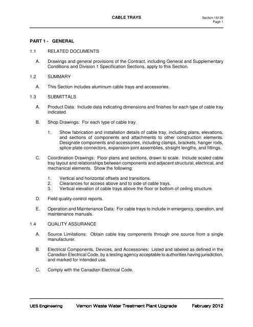
<strong>PART</strong> 1 - <strong>GENERAL</strong><br />
<strong>1.1</strong> <strong>RELATED</strong> <strong>DOCUMENTS</strong><br />
A. <strong>Drawings</strong> <strong>and</strong> general provisions of the Contract, including General <strong>and</strong> Supplementary<br />
Conditions <strong>and</strong> Division 1 Specification Sections, apply to this Section.<br />
1.2 SUMMARY<br />
A. This Section includes aluminum cable trays <strong>and</strong> accessories.<br />
1.3 SUBMITTALS<br />
A. Product Data: Include data indicating dimensions <strong>and</strong> finishes for each type of cable tray<br />
indicated.<br />
B. Shop <strong>Drawings</strong>: For each type of cable tray.<br />
1. Show fabrication <strong>and</strong> installation details of cable tray, including plans, elevations,<br />
<strong>and</strong> sections of components <strong>and</strong> attachments to other construction elements.<br />
Designate components <strong>and</strong> accessories, including clamps, brackets, hanger rods,<br />
splice-plate connectors, expansion-joint assemblies, straight lengths, <strong>and</strong> fittings.<br />
C. Coordination <strong>Drawings</strong>: Floor plans <strong>and</strong> sections, drawn to scale. Include scaled cable<br />
tray layout <strong>and</strong> relationships between components <strong>and</strong> adjacent structural, electrical, <strong>and</strong><br />
mechanical elements. Show the following:<br />
1. Vertical <strong>and</strong> horizontal offsets <strong>and</strong> transitions.<br />
2. Clearances for access above <strong>and</strong> to side of cable trays.<br />
3. Vertical elevation of cable trays above the floor or bottom of ceiling structure.<br />
D. Field quality-control reports.<br />
E. Operation <strong>and</strong> Maintenance Data: For cable trays to include in emergency, operation, <strong>and</strong><br />
maintenance manuals.<br />
1.4 QUALITY ASSURANCE<br />
A. Source Limitations: Obtain cable tray components through one source from a single<br />
manufacturer.<br />
B. Electrical Components, Devices, <strong>and</strong> Accessories: Listed <strong>and</strong> labeled as defined in the<br />
Canadian Electrical Code, by a testing agency acceptable to authorities having jurisdiction,<br />
<strong>and</strong> marked for intended use.<br />
C. Comply with the Canadian Electrical Code.<br />
UES Engineering<br />
Vernon Waste Water Treatment Plant Upgrade<br />
February 2012
1.5 DELIVERY, STORAGE, AND HANDLING<br />
CABLE TRAYS Section 16139<br />
Page 2<br />
A. Aluminum cable tray may be stored outside without cover, but shall be loosely stacked,<br />
elevated off the ground, <strong>and</strong> ventilated to prevent staining during storage.<br />
B. Store indoors to prevent water or other foreign materials from staining or adhering to cable<br />
tray. Unpack <strong>and</strong> dry wet materials before storage.<br />
<strong>PART</strong> 2 - PRODUCTS<br />
2.1 MANUFACTURERS<br />
A. Available Manufacturers: Subject to compliance with requirements, manufacturers offering<br />
products that may be incorporated into the Work include, but are not limited to, the<br />
following:<br />
2.2 MATERIALS AND FINISHES<br />
A. Cable Trays, Fittings, <strong>and</strong> Accessories: Aluminum, complying with NEMA VE 1, Aluminum<br />
Association's Alloy 6063-T6 for rails, rungs, <strong>and</strong> cable trays, <strong>and</strong> Alloy 5052-H32 or<br />
Alloy 6061-T6 for fabricated parts; with Type 316 stainless-steel splice-plate fasteners,<br />
bolts, <strong>and</strong> screws.<br />
2.3 CABLE TRAY ACCESSORIES<br />
A. Fittings: Tees, crosses, risers, elbows, <strong>and</strong> other fittings as indicated, of same materials<br />
<strong>and</strong> finishes as cable tray.<br />
B. Barrier Strips: Same materials <strong>and</strong> finishes as cable tray.<br />
C. Cable tray supports <strong>and</strong> connectors, including bonding jumpers, as recommended by cable<br />
tray manufacturer.<br />
2.4 WARNING SIGNS<br />
A. Lettering: 1-1/2 inch (40-mm) - high, black letters on yellow background with legend<br />
"WARNING! NOT TO BE USED AS WALKWAY, LADDER, OR SUPPORT FOR<br />
LADDERS OR PERSONNEL."<br />
2.5 SOURCE QUALITY CONTROL<br />
A. Perform design <strong>and</strong> production tests according to NEMA VE 1.<br />
<strong>PART</strong> 3 - EXECUTION<br />
3.1 CABLE TRAY INSTALLATION<br />
A. Comply with recommendations in NEMA VE 2. Install as a complete system, including all<br />
necessary fasteners, hold-down clips, splice-plate support systems, barrier strips, hinged<br />
horizontal <strong>and</strong> vertical splice plates, elbows, reducers, tees, <strong>and</strong> crosses.<br />
UES Engineering<br />
Vernon Waste Water Treatment Plant Upgrade<br />
February 2012
B. Remove burrs <strong>and</strong> sharp edges from cable trays.<br />
CABLE TRAYS Section 16139<br />
Page 3<br />
C. Make connections to equipment with flanged fittings fastened to cable tray <strong>and</strong> to<br />
equipment. Support cable tray independent of fittings. Do not carry weight of cable tray on<br />
equipment enclosure.<br />
D. Install expansion connectors where cable tray crosses building expansion joint <strong>and</strong> in cable<br />
tray runs that exceed dimensions recommended in NEMA VE 1. Space connectors <strong>and</strong><br />
set gaps according to applicable st<strong>and</strong>ard.<br />
E. Make changes in direction <strong>and</strong> elevation using st<strong>and</strong>ard fittings.<br />
F. Make cable tray connections using st<strong>and</strong>ard fittings.<br />
G. Sleeves for Future Cables: Install capped sleeves for future cables through firestop-sealed<br />
cable tray penetrations of fire <strong>and</strong> smoke barriers.<br />
H. Workspace: Install cable trays with enough space to permit access for installing cables.<br />
I. Install barriers to separate cables of different systems, such as power, communications,<br />
<strong>and</strong> data processing; or of different insulation levels, such as 208 <strong>and</strong> 600V.<br />
J. After installation of cable trays is completed, install warning signs in visible locations on or<br />
near cable trays.<br />
3.2 CABLE INSTALLATION<br />
A. Install cables only when cable tray installation has been completed <strong>and</strong> inspected.<br />
B. Fasten cables on horizontal runs with cable clamps or cable ties as recommended by<br />
NEMA VE 2. Tighten clamps only enough to secure the cable, without indenting the cable<br />
jacket. Install cable ties with a tool that includes an automatic pressure-limiting device.<br />
C. On vertical runs, fasten cables to tray every 18 inches (457 mm). Install intermediate<br />
supports when cable weight exceeds the load-carrying capacity of the tray rungs.<br />
D. In existing construction, remove inactive or dead cables from cable tray.<br />
E. Install covers after installation of cable is completed.<br />
3.3 CONNECTIONS<br />
A. Ground cable trays according to manufacturer's written instructions.<br />
B. Install an insulated equipment grounding conductor with cable tray, in addition to those<br />
required by The Canadian Electrical Code.<br />
3.4 FIELD QUALITY CONTROL<br />
A. After installing cable trays <strong>and</strong> after electrical circuitry has been energized, survey for<br />
compliance with requirements. Perform the following field quality-control survey:<br />
UES Engineering<br />
Vernon Waste Water Treatment Plant Upgrade<br />
February 2012
CABLE TRAYS Section 16139<br />
Page 4<br />
1. Visually inspect cable insulation for damage. Correct sharp corners, protuberances<br />
in cable tray, vibration, <strong>and</strong> thermal expansion <strong>and</strong> contraction conditions, which may<br />
cause or have caused damage.<br />
2. Verify that the number, size, <strong>and</strong> voltage of cables in cable tray do not exceed that<br />
permitted by the Canadian Electrical Code. Verify that communication or dataprocessing<br />
circuits are separated from power circuits by barriers.<br />
3. Verify that there is no intrusion of such items as pipe, hangers, or other equipment<br />
that could damage cables.<br />
4. Remove deposits of dust, industrial process materials, trash of any description, <strong>and</strong><br />
any blockage of tray ventilation.<br />
5. Visually inspect each cable tray joint <strong>and</strong> each ground connection for mechanical<br />
continuity. Check bolted connections between sections for corrosion. Clean <strong>and</strong><br />
retorque in suspect areas.<br />
6. Check for missing or damaged bolts, bolt heads, or nuts. When found, replace with<br />
specified hardware.<br />
7. Perform visual <strong>and</strong> mechanical checks for adequacy of cable tray grounding; verify<br />
that all takeoff raceways are bonded to cable tray.<br />
B. Report results in writing.<br />
END OF SECTION<br />
UES Engineering<br />
Vernon Waste Water Treatment Plant Upgrade<br />
February 2012