SCS G3P-8 Spin Coater - REMRSEC Facilities
SCS G3P-8 Spin Coater - REMRSEC Facilities
SCS G3P-8 Spin Coater - REMRSEC Facilities

You also want an ePaper? Increase the reach of your titles
YUMPU automatically turns print PDFs into web optimized ePapers that Google loves.
G3 <strong>Spin</strong> <strong>Coater</strong> Series<br />
Model <strong>G3P</strong>-8<br />
Operator’s Manual<br />
System Serial Number; ________________<br />
Prepared for: ________________________<br />
Make certain that everyone associated with this machine<br />
becomes knowledgeable about the material contained in this manual<br />
before using the equipment.<br />
7645 Woodland Drive, Indianapolis, IN 46278-2707<br />
Customer Service: P 317. 244.1200 F 317.240.2073<br />
E <strong>SCS</strong>customerservice@<strong>SCS</strong>coatings.com<br />
COPYRIGHT SPECIALTY COATING SYSTEMS
MODEL NO.<br />
<strong>G3P</strong>-8<br />
7645 WOODLAND DRIVE, - INDIANAPOLIS, IN 46278-2707 – PH. 800-356-8260<br />
SERIAL NO.<br />
VOLTS AMPS PHASE HZ<br />
INT. CAPACITY AMP MFG. DATE<br />
SCHEMATICS
05/27/10
OM-812-1027 Operator’s Manual Rev 13<br />
TABLE OF CONTENTS<br />
SECTION 1 SAFETY ..................................................................................................................... 1<br />
1.1 STANDARDS STATEMENT .................................................................................................... 1<br />
1.2 GENERAL HAZARDS .............................................................................................................. 1<br />
1.2.1 Hazard Icons ....................................................................................................................... 2<br />
1.3 POWER CORD (SHOCK) SAFETY .......................................................................................... 2<br />
1.4 SERVICING ............................................................................................................................... 2<br />
SECTION 2 OVERVIEW .............................................................................................................. 3<br />
2.1 DESCRIPTION .......................................................................................................................... 3<br />
SECTION 3 SPECIFICATIONS.................................................................................................... 5<br />
SECTION 4 INSTALLATION ....................................................................................................... 7<br />
SECTION 5 OPERATION ............................................................................................................. 9<br />
5.1 PRE-START ............................................................................................................................... 9<br />
5.2 FACILITIES PANEL ................................................................................................................. 9<br />
5.3 VACUUM CHUCK .................................................................................................................. 10<br />
5.4 LID ........................................................................................................................................... 10<br />
5.5 PROGRAMMING THE <strong>G3P</strong> .................................................................................................... 11<br />
5.5.1 <strong>G3P</strong> Control Panel ............................................................................................................ 11<br />
5.5.2 <strong>G3P</strong> Programming ............................................................................................................ 12<br />
5.5.3 Programming Hints and Tricks .......................................................................................... 13<br />
5.5.4 Recipe Example ................................................................................................................. 14<br />
5.6 SELECTING A PROGRAM TO RUN ...................................................................................... 16<br />
5.7 RUNNING ............................................................................................................................... 16<br />
5.8 ERROR MESSAGES ............................................................................................................... 17<br />
5.9 TROUBLESHOOTING ............................................................................................................ 18<br />
5.10 SHUTDOWN ........................................................................................................................... 18<br />
SECTION 6 MAINTENANCE ..................................................................................................... 19<br />
6.1 CLEANING.............................................................................................................................. 19<br />
6.2 DRAIN OPTION ...................................................................................................................... 19<br />
6.3 MAINTENANCE SCHEDULE ................................................................................................ 19<br />
6.4 VACUUM SWITCH ADJUSTMENT ...................................................................................... 20<br />
6.5 FLOW SWITCH ADJUSTMENT ............................................................................................. 20<br />
6.6 CHANGING THE FUSES ........................................................................................................ 21<br />
SECTION 7 REPLACEMENT PARTS ........................................................................................ 23<br />
OPTIONAL VACUUM CHUCKS ........................................................................................................ 23<br />
APPENDIX 27<br />
LIMITED WARRANTY POLICY ........................................................................................................ 27<br />
<strong>G3P</strong>-8 SPIN COATER TABLE OF CONTENTS I
Rev 13 Operator’s Manual OM-812-1027<br />
FORMS ................................................................................................................................................. 29<br />
About You… ....................................................................................................................................... 29<br />
About the Equipment… ...................................................................................................................... 29<br />
About Us… ........................................................................................................................................ 29<br />
VENDOR LITERATURE ..................................................................................................................... 31<br />
DRAWINGS ......................................................................................................................................... 33<br />
INDEX . ................................................................................................................................ 67<br />
II TABLE OF CONTENTS <strong>G3P</strong>-8 SPIN COATER
OM-812-1027 Operator’s Manual Rev 13<br />
TABLE OF FIGURES<br />
Figure 5-1: <strong>Facilities</strong> (Back) Panel ........................................................................................................... 9<br />
Figure 5-2: <strong>G3P</strong> Control Panel ............................................................................................................... 11<br />
Figure 5-3: <strong>G3P</strong> Display ........................................................................................................................ 12<br />
Figure 5-4: Example <strong>G3P</strong> Program ........................................................................................................ 15<br />
Figure 6-1: Vacuum Switch Adjustment ................................................................................................ 20<br />
Figure 6-2 Fuse Replacement ................................................................................................................ 21<br />
<strong>G3P</strong>-8 SPIN COATER TABLE OF CONTENTS III
Rev 13 Operator’s Manual OM-812-1027<br />
IV TABLE OF CONTENTS <strong>G3P</strong>-8 SPIN COATER
OM-812-1027 Operator’s Manual Rev 13<br />
SECTION 1<br />
SAFETY<br />
1.1 STANDARDS STATEMENT<br />
This equipment is designed to be used as described here. Operator safety and safe reliable product<br />
coating were key elements in the design. The equipment complies with all applicable sections of the<br />
NFPA article 79, the National Electric Code (NEC). All commercially standard components used in this<br />
machine have a minimum of UL and/or CSA ratings. Components built to CE standards have been used<br />
wherever possible. Any local or regional certifications required above and beyond the aforementioned<br />
are the responsibility of the customer.<br />
1.2 GENERAL HAZARDS<br />
WARNING: Improper operation or service of this equipment can result in serious<br />
injury or death. Read and understand this manual before operating or servicing<br />
this equipment.<br />
<br />
<br />
<br />
<br />
<br />
<br />
<br />
<br />
<br />
<br />
<br />
<br />
DANGER: This machine is not classified as "Intrinsically Safe." DO NOT use the G3 series<br />
spin coater in the presence of an explosive atmosphere.<br />
DANGER: Use only under an exhaust hood.<br />
WARNING: To avoid severe injury, do not touch or hold the shaft or chuck while it is rotating.<br />
WARNING: Purging is required as a safety factor to fill the interior of the machine and exclude<br />
dangerous gasses. N 2 or clean, dry air can be used when purging.<br />
WARNING: In case of a "Motion Error" (see page 17) the motor will spin freely, and will not<br />
be stopped by opening the lid. Wait until you are sure the chuck has stopped spinning before you<br />
open the lid.<br />
WARNING: Do not operate without lid in place to protect operator and others from injury as<br />
wafers or wafer parts may fly off rotating chuck.<br />
WARNING: To avoid electrical shock or injury, do not remove lid or try to access any internal<br />
parts, while machine is still plugged in. Before servicing the G3, DISCONNECT power cord<br />
from outlet and wait 10 minutes (high voltage may exist in the machine for some time after<br />
removal of power).<br />
CAUTION: The G3 series spin coater uses a ground type power plug, which must be connected<br />
to a grounded outlet to prevent electrical shock.<br />
IMPORTANT: Do not operate the spin coater with the drain hose disconnected or drained<br />
material may not go where it should.<br />
IMPORTANT: If the machine is purchased with an external vacuum pump, you must add oil<br />
to the pump. Let the pump sit for six hours with the oil prior to starting the pump. See the pump<br />
manual for additional details. Pump seals will burn out if proper instructions are not followed.<br />
CAUTION: Do not lift the machine using the control panel (keyboard) as a handle. Doing so<br />
could damage the machine and cause injury.<br />
CAUTION: Consult your Material Safety Data Sheets for information about any chemicals you<br />
use in your process, and their possible toxicity or reaction with the spin coater bowl or drain.<br />
<strong>G3P</strong>-8 SPIN COATER SECTION 1: SAFETY 1
Rev 13 Operator’s Manual OM-812-1027<br />
1.2.1 HAZARD ICONS<br />
The following symbols may occur at points throughout the rest of the manual. Note and read each<br />
warning before attempting any operations associated with it.<br />
This symbol warns of the potential for an ELECTRICAL SHOCK.<br />
This symbol signifies a GENERAL WARNING, which accompanying text will explain.<br />
1.3 POWER CORD (SHOCK) SAFETY<br />
Emergency Power Disconnect options: Use the power cord as a disconnecting device.<br />
To facilitate disconnect, make sure the power outlet for this cord is readily accessible to the<br />
operator.<br />
NOTE for international users: Select the plug that is rated for the supply circuit voltage that is available.<br />
The supply circuit must be overcurrent protected at a value not exceeding 6 amps.<br />
1.4 SERVICING<br />
Before servicing, remove all power. NOTE: High voltage may still be present after<br />
shutdown and disconnecting line power. Allow machine to set without power for 10<br />
minutes before servicing. If it becomes necessary to perform diagnostic service while<br />
certain areas of the machine still have power, use only qualified personnel. Follow all<br />
normal industrial safety practices when dealing with electrical components. Review and<br />
understand the electrical schematic before attempting any electrical diagnostic service.<br />
2 SECTION 1: SAFETY <strong>G3P</strong>-8 SPIN COATER
OM-812-1027 Operator’s Manual Rev 13<br />
SECTION 2<br />
OVERVIEW<br />
2.1 DESCRIPTION<br />
The G3 series is family of compact spin coaters for low production spin coating applications and<br />
experimentation.<br />
The G3's provide the ability to hold your product wafer with a vacuum chuck and spin that chuck at<br />
precise speeds and for controlled periods of time. Operations are extremely repeatable and are settable to<br />
0.1 second. The chuck is indexed back to its initial position at the end of each cycle, so that each wafer<br />
may be oriented the same way on the chuck. See §3 for actual specifications.<br />
Operation of the spin coater is controlled by a custom-designed controller. During a cycle, the product<br />
recipe number, spinning speed, and remaining time are displayed on a user interface screen. The<br />
acceleration and deceleration rates are calculated by the controller to provide various ramp profiles.<br />
Programmable machines have provisions to connect a foot pedal as a starter.<br />
The G3 (without the "P") holds a single recipe at a time. The recipe determines ramp up time, speed and<br />
dwell time at speed, and ramp down time. The G3 is available in the 8-inch bowl size only.<br />
The <strong>G3P</strong> can store up to 30 product recipes (programs). Each recipe offers a single setup step plus 20<br />
action steps, with each action step including the ability to specify RPM 1) a speed to attain; ramp 2) how<br />
quickly to change to that speed; and dwell 3) how log to remain at the desired speed.<br />
In addition, if the optional equipment is present, the <strong>G3P</strong>'s steps can control dispense switching and<br />
timing for each of four optional external operations (dispense coating material, dispense solvent, N 2<br />
release, and edge bead removal). Switching begins at the start of the step’s Dwell. The machines are<br />
available in bowl sizes of 8, 12, and 15 inches. Also available are interchangeable vacuum chucks.<br />
Use of this machine for anything but its intended purpose may create a safety hazard and voids the<br />
equipment warranty.<br />
<strong>G3P</strong>-8 SPIN COATER SECTION 2: OVERVIEW 3
Rev 13 Operator’s Manual OM-812-1027<br />
4 SECTION 2: OVERVIEW <strong>G3P</strong>-8 SPIN COATER
OM-812-1027 Operator’s Manual Rev 13<br />
SECTION 3<br />
SPECIFICATIONS<br />
The <strong>G3P</strong>-8 spin coater can store 30 recipes with a maximum of 20 action steps each.<br />
Speed<br />
Acceleration/ Deceleration<br />
Dwell (<strong>Spin</strong> Time) each step<br />
Dispense (switch) times (†)<br />
Dimensions<br />
Weight<br />
Power Input<br />
Vacuum Input (required)<br />
Purge Input (required)<br />
Drain<br />
OR<br />
0—9999 RPM<br />
Rev 13 Operator’s Manual OM-812-1027<br />
6 SECTION 3: SPECIFICATIONS <strong>G3P</strong>-8 SPIN COATER
OM-812-1027 Operator’s Manual Rev 13<br />
SECTION 4<br />
INSTALLATION<br />
Note for international applications: The spin coater is provided to international users with an<br />
unterminated power cord so that the appropriate power plug (non-locking 250V, 10A), may be attached.<br />
The plug must meet the requirements of IEC227 or IEC245. NOTE: The supply circuit must be<br />
overcurrent protected at a value not exceeding 6 amps.<br />
Do not apply power until all other connections have been made.<br />
• Place the machine on a solid, level surface, free from vibration and temperature extremes. For<br />
optimum performance, make sure the chuck is level.<br />
• Refer to the Specifications section or to the nameplate on the machine for electrical requirements.<br />
• Position the bowl with its drain hole aligned over the drainway.<br />
• The machine will not operate without purging N 2 or clean, dry air (0.55 scfm) connected to the<br />
“N 2 ” port in the back of the machine. Purging N 2 or clean, dry air is required as a safety factor to<br />
fill the interior of the console and exclude dangerous gasses.<br />
• Vacuum (internal or external) is also required for the machine to operate. Connect external<br />
vacuum to the “Vacuum” port on the Utility Panel, or use the optional pneumatic-powered<br />
vacuum pump.<br />
• Install and connect options before connecting the spin coater power<br />
• NOTICE: See startup instructions for the optional external vacuum pump in the technical<br />
section. Improper oil levels may damage the pump. After filling, let the pump sit for six hours<br />
before using it.<br />
Note that the machine is not for use in a hazardous atmosphere.<br />
<strong>G3P</strong>-8 SPIN COATER SECTION 4: INSTALLATION 7
Rev 13 Operator’s Manual OM-812-1027<br />
8 SECTION 4: INSTALLATION <strong>G3P</strong>-8 SPIN COATER
OM-812-1027 Operator’s Manual Rev 13<br />
SECTION 5<br />
OPERATION<br />
This machine is designed for use in a normal laboratory or manufacturing working environment. In<br />
addition, the installation should be free from temperature extremes and vibration.<br />
5.1 PRE-START<br />
1. Connect the N 2 or clean, dry air purge supply and vacuum (if the optional internal pneumaticpowered<br />
vacuum pump is used, only the N 2 or clean, dry air purge is needed).<br />
NOTE: The machine will not operate without the vacuum and N 2 or clean, dry air purge.<br />
2. Connect any optional devices: footswitch, dispensers, N 2 , etc.<br />
3. Attach power cord (spin coater, and external vacuum pump if so equipped) to properly grounded<br />
outlet. (See technical section, and pump operation instructions for starting the vacuum pump.)<br />
4. Verify that the vacuum chuck is secure.<br />
5. Turn power On using the POWER switch located on the rear panel.<br />
Remember that the machine will not run unless programmed, and that the top must be opened and closed<br />
before each cycle (indicating that material has been placed in the spin coater).<br />
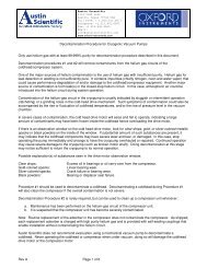
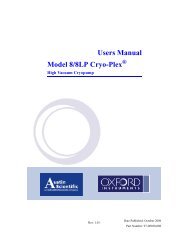
5.2 FACILITIES PANEL<br />
Fuse F1<br />
Pry Slot<br />
Voltage<br />
Indicator<br />
Window<br />
Computer<br />
Interface<br />
Power<br />
Switch<br />
Figure 5-1: <strong>Facilities</strong> (Back) Panel<br />
FOOTSWITCH/ DISPENSER:<br />
1. Accepts a foot pedal/switch (if desired, to start the cycle).<br />
<strong>G3P</strong>-8 SPIN COATER SECTION 5: OPERATION 9
Rev 13 Operator’s Manual OM-812-1027<br />
2. On the <strong>G3P</strong> spin coater only, provides control signals for an (optional) unit for dispensing materials<br />
during the cycle. Note: On the <strong>G3P</strong>, the foot pedal may be connected through the dispenser.<br />
FUSE/VOLTAGE SLOT<br />
Use this for access to the F1 Fuse Carrier.<br />
POWER SWITCH<br />
The switch turns the machine power ON and OFF.<br />
FUSE F1:<br />
Line fuse. Replace with an exact electrical equivalent only.<br />
FUSE F2:<br />
Secondary (70 VDC) fuse. Replace with an exact electrical equivalent only.<br />
FUSE F3:<br />
Secondary (18.5 VDC) fuse. Replace with an exact electrical equivalent only.<br />
COMPUTER INTERFACE<br />
A projected future option that would allow access to programming and operation directly from computer.<br />
VACUUM:<br />
The external vacuum supply connects here, using 1/4" OD tube fitting (430 to 635 mm Hg or 17 to 25<br />
inches Hg). NOTICE: The machine will not complete a cycle without vacuum or the optional vacuum<br />
pump.<br />
If the optional internal vacuum pump is present, this port becomes the exhaust port for that pump (and<br />
external pumps cannot be used).<br />
NOTICE: See startup instructions for optional vacuum pump in the technical section. Improper oil levels<br />
may damage pump. After filling, let the pump sit for six hours before using the pump.<br />
N2 SUPPLY:<br />
This is the connection for the N 2 or clean, dry air supply to maintain positive pressure in the enclosure<br />
(0.55 scfm at 2 psi nitrogen or clean, dry air). NOTICE: The machine will not operate without N 2 or<br />
clean, dry air.<br />
5.3 VACUUM CHUCK<br />
The chucks are machined to close tolerances and provide an exceptionally flat, rigid surface for mounting<br />
wafers of different sizes, weights, and shapes. The cross scroll pattern distributes the vacuum over the<br />
chuck surface to hold the wafer while spinning at high RPM. This pattern also allows rapid vacuum<br />
release.<br />
Proper chuck selection should be based upon wafer size and rigidity. The proper chuck diameter is 1/4 to<br />
1 inch (0.6 to 2.5cm) smaller than the wafer diameter. The entire wafer should be supported if it is<br />
flexible, fragile, or when it is to be wiped or brushed during cleaning.<br />
Proper centering is done manually, but the use of templates and measurements can aid in this operation.<br />
Chuck size and weight affect the spin coater. You must program the chuck size into the recipes for the<br />
programmable spin coater, in "Step 0." See §5.5.2 and §5.5.4.<br />
5.4 LID<br />
The lid has an Open/Close switch. You cannot run a recipe with the lid open. In addition, you must open<br />
the lid after each cycle is completed. This helps the operator avoid accidentally dispensing twice on the<br />
10 SECTION 5: OPERATION <strong>G3P</strong>-8 SPIN COATER
OM-812-1027 Operator’s Manual Rev 13<br />
same wafer. If the lid is opened during a cycle, electronic breaking will be applied*. If a dispense action<br />
is in process, it will be terminated.<br />
*In rare instances (heavy chuck, high rotation speed) a "Motion Error" may occur; the chuck will then<br />
coast to a stop. This does not damage the machine.<br />
5.5 PROGRAMMING THE <strong>G3P</strong><br />
With the <strong>G3P</strong> programmable spin coater, you can enter multiple recipes and direct it to do complex<br />
operations.<br />
Figure 5-2: <strong>G3P</strong> Control Panel<br />
5.5.1 <strong>G3P</strong> CONTROL PANEL<br />
• MODE: This pushbutton moves the <strong>G3P</strong> between the Program/Edit mode and the Run mode.<br />
Each time you press it, you change to the other mode.<br />
In the Run mode, the following <strong>G3P</strong> spin coater controls are active:<br />
• START: This pushbutton starts a cycle, if all conditions are correct. (For example, the <strong>G3P</strong> must<br />
be in the run mode, the vacuum and purge N 2 sensors must be satisfied, and it may be necessary<br />
to open and close the load lid.)<br />
• CLR-ERROR: If the machine is in the error mode, it will not reset or run. This pushbutton<br />
clears (resets) a machine error so that the MODE and START buttons become active again.<br />
• STOP: This pushbutton will stop rotation even if the <strong>G3P</strong> is in mid-cycle. NOTE: If the chuck<br />
and wafer have unusually great momentum, a Motion Error may occur and the electronic<br />
<strong>G3P</strong>-8 SPIN COATER SECTION 5: OPERATION 11
Rev 13 Operator’s Manual OM-812-1027<br />
breaking may fail; the chuck will coast to a halt. Do not open the lid until you are sure the<br />
rotation has stopped completely.<br />
In the Program/Edit mode, the following <strong>G3P</strong> controls are active. You are able to enter new recipes<br />
and modify the settings of existing recipes.<br />
• ENTER: This pushbutton "enters" (stores) the data you just entered and advances the cursor to<br />
the next control block. It is important to use ENTER in order to make sure the data is stored in<br />
the recipe. (Without ENTER, the data is ignored.)<br />
• The and ("Set Values"): Like the basic G3, the <strong>G3P</strong> has arrows that cause the control<br />
variables (seconds or RPM) to increase or decrease. (Press and hold to get bigger changes; the<br />
counter will speed up.)<br />
• The and ("Navigation"): These arrows can move the cursor to the next/previous data block.<br />
NOTE: The arrows are best used when moving around in a recipe to find an item you wish to<br />
change; always use the ENTER button after entering/changing an item, so that the data is stored.<br />
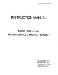
5.5.2 <strong>G3P</strong> PROGRAMMING<br />
In the Program/Edit mode (see Mode key, above), you can make and save up to 30 recipes (programs,<br />
cycles), and program up to 20 steps into each recipe. A step consists of setting up to five variables<br />
(Ramp, RPM, Dwell, Disp., and Time). See the following and the<br />
Pointer<br />
example (Figure 5-4). In the following, the text explains each<br />
display item, then the points out how to use that item.<br />
NOTE that you must program for the size of chuck being used; this<br />
affects speed control parameters. Do this by setting the size in<br />
Step 0 (mentioned in the following steps).<br />
1. Enter the Program/Edit mode by pressing the MODE button.<br />
A pointer will appear in the display, next to Recipe. (See the<br />
figure to the right.)<br />
>Recipe: _____<br />
Step:_____ Ramp:_____<br />
RPM: _____ Dwell:_____<br />
Disp:_____ Time: _____<br />
Figure 5-3: <strong>G3P</strong> Display<br />
2. Recipe: (30 Recipes, identified by number) Select any recipe number to edit its variables or create a<br />
new set from scratch. [NOTE: To remove all the old programming from a recipe, select the recipe<br />
number and press CLR/ERROR, then press ENTER.]<br />
Use the and to select a recipe number, then press ENTER. The recipe number will be<br />
entered and the pointer will move to Step.<br />
3. Step: (Step 0* plus 20 steps) Each step contains 5 variables, or commands, that you use to program<br />
the spin coater (Ramp, RPM, Dwell, Disp, & Time). Steps are executed in order from 1 to 20;<br />
unlike computer programming, there are no "Do Loops" or "Jump To" commands. (If you don't need<br />
all 20 steps, refer to Programming Hint #2, on the following page.)<br />
The step number will normally increment properly as you program, and won't require changing;<br />
You accept the step # by pressing ENTER and the pointer will move to Ramp. [If you wish to<br />
modify any step, you can simply use the and to set the Step number to the desired step and then<br />
move with the and to any item in that step and change it. Always press ENTER to make sure<br />
the changes are actually stored.]<br />
4. Ramp: (0 to 25.5 seconds) This number tells the spin coater how many seconds to take to accelerate<br />
or decelerate to the new speed (RPM). If Ramp is set to zero, the spin coater will try to comply; but<br />
if the required change of speed is too great, a Motion Error may occur (see "Error Messages," page<br />
17).<br />
12 SECTION 5: OPERATION <strong>G3P</strong>-8 SPIN COATER
OM-812-1027 Operator’s Manual Rev 13<br />
When the pointer is at Ramp, use the and to set the Ramp Seconds. Then press ENTER and<br />
the number will be stored and the pointer will move to RPM.<br />
5. RPM: (0 to 9999 RPM) This is the rotational speed for the spin coater for this step.<br />
When the pointer is at RPM, set the speed by using the and . Press ENTER and the number<br />
will be stored and the pointer will move to Dwell.<br />
6. Dwell: (0 to 999 seconds) This is how long to spin at the RPM you just selected.<br />
When the pointer is at Dwell, set the time by using the and . Press ENTER and the number<br />
will be stored and the pointer will move to Disp.<br />
7. Disp: (None, Coating, Edge, Solvent, N 2 , [1, 2, 4, 6, 8, 10, 12]*) If you have the optional hardware,<br />
you can select which external dispense function (Disp) to control during this step. The function will<br />
be turned on at the beginning of Dwell; its duration will be controlled by the Time variable (next).<br />
Possible options are: coating material, N 2 , solvent, edge bead removal, or none. This will not be<br />
activated unless the next variable (Time) is changed from zero.<br />
When the pointer is at Disp, select from these options by using the and , then press ENTER<br />
to accept the choice, and the pointer will move to Time.<br />
8. Time: (0 to 10 seconds) This setting determines how long the Disp. function will be turned On. If<br />
Disp is set to "None," then the Time setting does nothing. Setting Time to something other than zero<br />
in the Step 0 turns off Homing after a recipe is completed.<br />
When the pointer is at Disp, set how long to have that optional function turned On by using the <br />
and . (If you set the Time to be longer than the Dwell setting, then dwell will be extended to<br />
accommodate the Disp. action.) Press ENTER and the number is stored and the pointer moves to the<br />
(next numbered) Step. Continue this process of entering steps until you have completed your recipe.<br />
9. After entering all of the desired steps for your recipe, use the following to exit properly.<br />
• If there are any leftover steps at the end with actions/numbers in them, you must remove them.<br />
Display an unwanted step. With the pointer at Step, press CLR/ERROR to clear it, and press<br />
ENTER. Use the and to examine the next steps and clear them if necessary.<br />
• When done cleaning up, be sure to press ENTER to store the changes or they will be lost.<br />
• Press MODE to return to operation, or select another recipe to edit/create (using and and<br />
and ).<br />
* PROGRAMMING NOTE: "Step 0" allows you to tell the program what size vacuum chuck you will<br />
use with the recipe. This is important so that the spin coater give the right amount of force to<br />
accomplish the desired ramps and speeds. REMEMBER to program in the chuck diameter in the<br />
Disp blank on Step 0. ALSO, setting the Time to something different than zero tells the spin coater<br />
NOT to return the chuck to its original position after completing the recipe (by skipping the homing<br />
process, you save processing time).<br />
5.5.3 PROGRAMMING HINTS AND TRICKS<br />
Note the following hints to make it easier and faster to enter a recipe.<br />
1. To remove an entire recipe: Place the pointer at Recipe and select the desired recipe number; press<br />
CLR/ERROR and then ENTER. All steps will be removed.<br />
2. To remove a step at the END of a recipe: Place the pointer at Step and select the step number to be<br />
removed; then press CLR/ERROR and then ENTER. Check to see that there are no more steps after<br />
that.<br />
3. To remove a step from the MIDDLE of a recipe: (e.g., you discover you have entered a step twice,<br />
and want to remove the extra without moving all the rest of the steps) Set all of the variables to zero<br />
except the RPM; set that to be the same as the preceding step. Press ENTER<br />
<strong>G3P</strong>-8 SPIN COATER SECTION 5: OPERATION 13
Rev 13 Operator’s Manual OM-812-1027<br />
4. To edit or modify a step's variables: Go to those particular variables by using the ENTER or the<br />
and and then change the variable by using the and . REMEMBER to press ENTER<br />
afterwards, or the change will not be kept.<br />
5. To extend a function (ramp or dispense) beyond its normal time limit: Use two similar steps.<br />
e.g., For a ramp from 1000 to 2000 RPM over 40 seconds, ramp from 1000 to 1500 over 20 seconds<br />
in the first step (and set Dwell to zero); then ramp from 1500 to 2000 over 20 seconds in the next<br />
step. Use the same idea for extra long dispense by employing two steps instead of one.<br />
6. To dispense before spinning: Simply set the RPM to zero for the step. Select the dispense<br />
function and set the Time (if you want the chuck to remain still for some time after the dispense is<br />
complete, set the Dwell to be longer than the Time). Then use the next step to ramp up to the desired<br />
speed.<br />
7. To have two dispense operations, one right after the other (same or different): Create a step that<br />
has the first dispense operation (Coating, perhaps) with zero Dwell time and Dispense time as<br />
desired. Use the next step to perform the second Disp. function without ramping up or down in speed.<br />
8. Remember that you must press ENTER to accept any step's programming. If you move about using<br />
the navigation arrows ( and ), your changes are not entered and saved. If you change a setting,<br />
be sure to press ENTER next. (An ENTER at any time saves all previous changes that were made<br />
during that step.)<br />
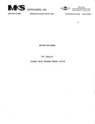
5.5.4 RECIPE EXAMPLE<br />
Great flexibility is available in <strong>G3P</strong> recipes. Figure 5-4 shows RPM versus time for a recipe that<br />
demonstrates some of the different actions.<br />
• The length of a step is shown across the bottom with an arrow. (Step 1 is 18 seconds, total.)<br />
• Vertical lines and a number (total seconds) mark each event (start or stop of any ramp, dispense,<br />
or dwell).<br />
• Heavy lines show the two dispense operations.<br />
• The numbers at the left show the speeds (RPM) used in this recipe.<br />
• Boxes across the top illustrate the recipe entries for the seven steps.<br />
Note some of the special capabilities accomplished by the recipe:<br />
• Long periods of the same function can be accomplished using multiple steps (Steps 3 & 4).<br />
• Sudden speed changes are accomplished by setting Ramp time to zero or a very low number (Step<br />
5). The actual time required is a function of the size of speed change and the amount of weight<br />
being spun.<br />
• Pauses at zero RPM can be programmed into the middle of a recipe (Step 5). It is even possible<br />
to program a dispense step at zero RPM if desired.<br />
• Dispensing (option): Two dispense options can be employed, one right after the other and at the<br />
same RPM (Steps 1 & 2). They could follow more closely if Dwell 1 were set to 4 instead of 10.<br />
• Ramps to different speeds and employing different Accel/Decel rates can be combined<br />
(Steps 6 & 7).<br />
Here is a more detailed explanation of the figure, listing and discussing each step. To help keep things<br />
straight, the settings for Step1 will be called Ramp1, RPM1, Dwell1, etc.<br />
Step 0 is the step that tells the spin coater how large the vacuum chuck is. Enter the size in the Disp<br />
blank by selecting the number that (most nearly) represents the diameter of the chuck. Homing: to stop<br />
14 SECTION 5: OPERATION <strong>G3P</strong>-8 SPIN COATER
OM-812-1027 Operator’s Manual Rev 13<br />
the chuck from returning to the Home position at the end of the run, set the step 0 Time to some number<br />
other than 0.<br />
Step 1 begins with a Ramp1-- 8 seconds up to an RPM1 of 2000. Dwell1 is set to keep the speed at<br />
2000 for 10 seconds. Disp1 is set to COAT; the dispensing always begins as soon as the dwell does. The<br />
dispensing Time1 is 4 seconds (as shown by the heavy line), and the dwell continues until its 10 seconds<br />
is up.<br />
Step 2 begins at 18 seconds. It has no Ramp2 time and also has the same speed (2000 RPM) so it<br />
appears to be a continuation of step 1. Its Dwell2 is set to 10 seconds (combined with step 1 this gives a<br />
total dwell of 20 seconds at 2000 RPM). Disp2 is set to N 2 and the Time2 is 7 seconds (of N2<br />
dispensing).<br />
Step 3 begins at 28 seconds on the figure, and has a 15-second Ramp3 down to an RPM3 of 1400. The<br />
Dwell3 is set to 0 seconds and there is no Disp3. NOTE that this is half of a 30-second ramp down to<br />
800. Since a 30 second long ramp is not possible, the programmer used two 15-second ramps.<br />
Step 4 is the continuation of the ramp down. The Ramp4 is 15, and the RPM4 is 800.<br />
2000<br />
STEP 1<br />
Ramp1 = 8<br />
RPM 1 2000<br />
Dwell 1 = 10<br />
Disp 1 = COAT<br />
Time 1 = 4<br />
STEP 2<br />
Ramp 2 = 0<br />
RPM 2 = 2000<br />
Dwell 2 = 10<br />
Disp 2 = N2<br />
Time 2 = 7<br />
STEP 3<br />
Ramp 3 = 15<br />
RPM 3 = 1400<br />
Dwell 3 = 0<br />
Disp 3 = NONE<br />
Time 3 = 0<br />
STEP 4<br />
Ramp 4 = 15<br />
RPM 4 = 800<br />
Dwell 4 = 0<br />
Disp 4 = NONE<br />
Time 4 = 0<br />
STEP 5<br />
Ramp 5 = 0<br />
RPM 5 = 0<br />
Dwell 5 = 4<br />
Disp 5 = NONE<br />
Time 5 = 0<br />
STEP 6<br />
Ramp 6 = 3<br />
RPM 6 = 2000<br />
Dwell 6 = 0<br />
Disp 6 = NONE<br />
Time 6 = 0<br />
STEP 7<br />
Ramp 7 = 3<br />
RPM 7 = 0<br />
Dwell 7 = 0<br />
Disp 7 = NONE<br />
Time 7 = 0<br />
1400<br />
800<br />
8 12 18 25 28<br />
43 58<br />
62<br />
68<br />
Figure 5-4: Example <strong>G3P</strong> Program<br />
Step 5 tries to cause an instant stop, followed by 4 seconds without any spinning. The Ramp5 is 0, and<br />
the RPM5 is 0. The Dwell5 is set to 4 seconds. If the motor can stop quickly enough, the cycle will<br />
continue—if the momentum is too great and the motor cannot stop quickly enough, there will be a<br />
“Motion Error.: See the error messages on following page. To avoid the motion error, set Ramp5 to<br />
allow a short amount of time for the ramp down.<br />
Steps 6 & 7: consist of two ramps with no dwell time. RPM6 simply goes up to 2000 in the Ramp6 time<br />
of 3 seconds and RPM7 takes it back down to 0 in the Ramp7 time of 3 seconds. If necessary, the Ramp<br />
could be set to longer times, to avoid the motion error.<br />
65<br />
<strong>G3P</strong>-8 SPIN COATER SECTION 5: OPERATION 15
Rev 13 Operator’s Manual OM-812-1027<br />
5.6 SELECTING A PROGRAM TO RUN<br />
After the spin coater has completed its startup cycle, you can press START and it will attempt* to run<br />
whatever recipe is shown on its display. If there is no recipe, you must enter/select one.<br />
To select a different recipe on the <strong>G3P</strong> press MODE, change the recipe number, press ENTER, and then<br />
exit the Program/Edit mode by pressing MODE again.<br />
NOTE: The first step shown is numbered "0" and called Step Zero. It is used to tell the spin coater what<br />
size vacuum chuck is being used (enter the diameter in inches in the step 0 Disp blank). This is important<br />
for the control mechanism, always use the chuck that matches the size called for in the recipe. If different<br />
size chucks are used, you can make recipes for each size of chuck.<br />
ALSO in step 0 is the ability to turn off the automatic homing after each run (thus saving some time). Set<br />
the Time blank to some number larger than 0 to disable homing.<br />
*The spin coater will not run if the vacuum, lid open/close, and N 2 or clean, dry air purge requirements<br />
are not fulfilled. See the Troubleshooting section of this manual if a run failure occurs.<br />
5.7 RUNNING<br />
1. Make sure you are in the Run mode and the proper recipe is selected (select recipe in the<br />
Recipe/Edit mode).<br />
2. Make sure you have the proper size chuck–corresponding to the size called for in the Disp blank<br />
of Step Zero.<br />
3. Place the wafer on the vacuum chuck (wafer must be centered for proper operation).<br />
4. Close lid. Do not open the lid during a cycle; the cycle will be terminated and there is potential<br />
for injury.<br />
5. Go to the Run mode, and press START to begin a cycle.<br />
6. During the cycle, the display will show the Recipe number, and the approximate RPM and time<br />
remaining.<br />
7. At the end of each cycle, the vacuum chuck will slowly rotate to the "Home" position (unless<br />
programmed to not Home in the Step 0 programming). The display will say REMOVE<br />
COATED PARTS.<br />
8. Open the lid, remove the coated part, and place the next part on the chuck. NOTE: After each<br />
cycle, the spin coater lid must be opened and closed before the next cycle will run. This helps<br />
avoid spinning the same wafer twice by accident.<br />
9. You can stop rotation at any time by pressing STOP (in some instances the inertia of the rotating<br />
chuck can overpower the motor brake and cause a "Motion Error"). A "Short Cycle" error will<br />
occur if the lid is opened or the STOP button is pressed during a cycle.<br />
10. The CLR ERROR button will reset the machine if an error occurs. Pressing Start begins at the<br />
start of the current recipe.<br />
11. If process is to be repeated, go to step 1.<br />
16 SECTION 5: OPERATION <strong>G3P</strong>-8 SPIN COATER
OM-812-1027 Operator’s Manual Rev 13<br />
5.8 ERROR MESSAGES<br />
If the display light does not come on after connecting the power and turning on the power switch, check<br />
that the N 2 or clean, dry air purge is connected and has a pressure of at least 2 psi. Correct the cause of<br />
the error and press STOP/CLR ERROR to ready the machine for operation.<br />
Error Message Reason Remedy<br />
CHECK VACUUM .<br />
SHORT CYCLE<br />
1. Unable to hold vacuum.<br />
OR…<br />
2. No vacuum present.<br />
1. Unable to complete the<br />
process. Lid is opened<br />
during cycle<br />
2. Loss of vacuum.<br />
3. Stop button is pushed<br />
during a cycle.<br />
1. Make sure wafer is on the chuck.<br />
2. Check the vacuum line connection.<br />
1. To start a new cycle, clear the error,<br />
open/close lid.<br />
2. Check connections.<br />
3. To start a new cycle, clear the error,<br />
open/close lid.<br />
MOTION ERROR<br />
LID OPEN<br />
REMOVE COATED<br />
PARTS<br />
1. Motor could not follow the<br />
instructions given by the<br />
Recipe.<br />
2. Error in speed sensing<br />
circuitry.<br />
1. The lid switch indicates that<br />
the lid is open.<br />
1. Not an error, but a reminder<br />
that the cycle is complete<br />
and coated parts need to be<br />
removed.<br />
1. Ramp time too short, allow more<br />
time; check step 0 chuck size.<br />
2. Electronic or encoder problem– get<br />
service check step 0 chuck size.<br />
1. Close the lid or get switch fixed.<br />
1. Open lid, remove parts. Message<br />
will clear automatically.<br />
NOTE: When there is a Motion Error, power to the motor is cut and the chuck coasts to a stop.<br />
<strong>G3P</strong>-8 SPIN COATER SECTION 5: OPERATION 17
Rev 13 Operator’s Manual OM-812-1027<br />
5.9 TROUBLESHOOTING<br />
Refer to the Error messages in the previous section.<br />
PROBLEM<br />
<strong>Spin</strong> coater will not<br />
power up.<br />
Cycle will not start<br />
Cycle starts, but<br />
immediately stops<br />
Displayed time or<br />
RPM does not seem<br />
exact.<br />
Recipe "breaks" when<br />
changing speed.<br />
Other performance<br />
irregularities<br />
POSSIBLE CAUSE<br />
A N 2 or clean, dry air purge is not<br />
present, or inadequate flow.<br />
1. Error from previous cycle.<br />
2. Wrong/invalid recipe.<br />
3. Vacuum not present<br />
4. Lid open/close not sensed, or lid still<br />
open.<br />
1. Vacuum lost.<br />
2. Recipe problem.<br />
The display is an approximation, only<br />
updated when the control circuitry has<br />
available time. Use it only to verify the<br />
correct recipe choice and steps, and as a<br />
rough report on time and speed.<br />
Steep ramps are harder for the motor to<br />
accomplish. If the motor cannot change<br />
the speed fast enough a Motion Error<br />
occurs. The motor/chuck spin freely to a<br />
halt and the error message is displayed.<br />
Verify or provide a N 2 or clean, dry<br />
air purge. Have maintenance check<br />
sensor FLS-1.<br />
1. Press CLR ERROR<br />
2. Enter, check, or select a recipe<br />
3. Verify or provide necessary<br />
vacuum. Have maintenance check<br />
sensors FLS-1, VS-1.<br />
4. Open and close lid. . Have<br />
maintenance check sensor S1.<br />
1. Check placement of substrate on<br />
chuck. Check vacuum supply.<br />
2. Review, edit, and re-enter recipe<br />
as needed.<br />
For exact timing and speed, use<br />
external test equipment, and adjust<br />
the recipe as needed. Actual<br />
performance is very repeatable.<br />
Change the recipe to allow a more<br />
gradual speed change.<br />
Chuck Size considerations. The control program takes into account the chuck<br />
size (actually the chuck's moment of inertia). A customized chuck may cause<br />
some irregularities in performance if its mass/inertia are different from the<br />
anticipated chuck. If a custom chuck seems heavier than a similar sized standard<br />
chuck, select a larger size in "Step 0"; if the custom chuck seems lighter, choose a<br />
smaller size in "Step 0."<br />
5.10 SHUTDOWN<br />
1. Turn power OFF with the POWER switch located on the rear panel.<br />
2. Carefully remove vacuum chuck.<br />
3. Clean vacuum chuck and bowl thoroughly using the proper solvents.<br />
18 SECTION 5: OPERATION <strong>G3P</strong>-8 SPIN COATER
OM-812-1027 Operator’s Manual Rev 13<br />
SECTION 6<br />
MAINTENANCE<br />
6.1 CLEANING<br />
Use an appropriate solvent to clean the lid and the bowl; avoid damaging the bowl, lid, or drain hose.<br />
When using solvents such as N-Methylpyrrolidone (NMP) take care to avoid contact with the painted<br />
surfaces. These solvents will damage/remove the paint.<br />
6.2 DRAIN OPTION<br />
Use small amount of solvent to clean the left over material in the drainway and hose.<br />
If the material has cured inside the hose, replace the hose. Make sure to use appropriate "compatible"<br />
hose material.<br />
Never operate the spin coater with the hose disconnected from the bowl drain.<br />
It may cause damage to the machine and possible injury to the operator.<br />
6.3 MAINTENANCE SCHEDULE<br />
Frequency Task Responsibility<br />
As Needed Clean out bowl Operator<br />
Daily Clean, Check the N 2 or clean, dry air connections Operator<br />
Weekly Check hoses & fittings, electrical connections Maintenance<br />
Periodically<br />
Refer to vendor literature to maintain associated<br />
components<br />
As appropriate<br />
<strong>G3P</strong>-8 SPIN COATER SECTION 6: MAINTENANCE 19
Rev 13 Operator’s Manual OM-812-1027<br />
6.4 VACUUM SWITCH ADJUSTMENT<br />
See Figure 6-1. The Vacuum switch may need adjustment if the “Check Vacuum” error is displayed but<br />
no cause for it is apparent (the vacuum pump is working and the hose & motor shaft hole are not<br />
blocked). In that case:<br />
ADJUST<br />
VACUUM<br />
SWITCH<br />
COM<br />
1. Turn the vacuum adjust screw fully CW and turn on the machine and vacuum.<br />
2. Push the START button.<br />
3. While the cycle is running, slowly turn the vacuum adjust counterclockwise until the machine<br />
stops and the "CHECK VACUUM" messages is displayed.<br />
4. Turn back ¼ turn (clockwise).<br />
Verify machine operation.<br />
N.O. N.C.<br />
Figure 6-1: Vacuum Switch Adjustment<br />
6.5 FLOW SWITCH ADJUSTMENT<br />
The flow switch is properly adjusted before the spin coater is shipped; if something should make<br />
readjustment necessary follow the appropriate procedure.<br />
Machines with external vacuum pump:<br />
1. With machine turned On, adjust flow with incoming pressure regulator up from zero until flow switch<br />
actuates (characters will appear on machine display).<br />
2. Verify actual flow of at least 0.55 cfm using an external gauge.<br />
3. The procedure is complete. Verify machine operation.<br />
Machines with internal vacuum pump:<br />
1. Turn power off; remove air pressure.<br />
2. Remove the muffler from the top of the flow switch and connect a flow meter.<br />
3. Set the incoming pressure to 60-80 psi.<br />
4. Adjust the needle valve (at the bottom of the flow switch) to give 0.55 cfm.<br />
5. Remove air pressure, then remove the flow meter and replace the muffler.<br />
6. The procedure is complete. Verify machine operation.<br />
20 SECTION 6: MAINTENANCE <strong>G3P</strong>-8 SPIN COATER
OM-812-1027 Operator’s Manual Rev 13<br />
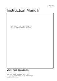
6.6 CHANGING THE FUSES<br />
Fuses F2 and F3 are in commonly used fuse carriers. Turn the cap with a small flat-blade screwdriver<br />
and pull out the fuse and carrier. Replace with only with an exact electrical equivalent.<br />
Fuse F1 is in the main power cord/switch assembly. Note that the correct voltage (115V or 230V) shows<br />
through the window near the top of the assembly.<br />
1. Above the voltage indication window are two notches. Use a small flat blade screwdriver to pry open<br />
the hinged cover.<br />
2. Inside, is the fuse carrier. Space at the sides will allow you to pry the carrier out. Note which side of<br />
the carrier has the fuse in it.<br />
3. Replace the fuse with an exact electrical equivalent. Make sure the fuse is in the proper side of the<br />
carrier.<br />
4. Return the carrier and press it fully into its holder. Make sure the writing for the correct voltage will<br />
show through the window when the cover is snapped back into place.<br />
5. Press the cover into place (it will snap closed if the fuse carrier is properly seated), and check to see<br />
that the proper voltage number shows through the window.<br />
Fuse F1<br />
Pry Slot<br />
Voltage Indicator<br />
Window<br />
Computer<br />
Interface<br />
Power Switch<br />
Figure 6-2 Fuse Replacement<br />
<strong>G3P</strong>-8 SPIN COATER SECTION 6: MAINTENANCE 21
Rev 13 Operator’s Manual OM-812-1027<br />
22 SECTION 6: MAINTENANCE <strong>G3P</strong>-8 SPIN COATER
OM-812-1027 Operator’s Manual Rev 13<br />
SECTION 7<br />
REPLACEMENT PARTS<br />
NOTE: Foldout drawings showing major assemblies for the spin coater are included in the back of this<br />
manual (the large folded pages). To help you identify items, we have numbered them on the drawing and<br />
in the left-most column of the bill of material listing on the drawing.<br />
OPTIONAL VACUUM CHUCKS<br />
Accessory chucks for <strong>SCS</strong> <strong>Spin</strong> <strong>Coater</strong>s are available in several materials including stainless steel<br />
(standard), hard anodized aluminum, DELRIN, and Teflon. Chuck size is specified by the user according<br />
to substrate dimension requirements. Chuck components are machined to close tolerances for flatness and<br />
rigidity, and a cross pattern to distribute vacuum across mounting surfaces. A chuck size ¼-inch to 1-inch<br />
less than the substrate diameter is recommended. Fragile substrates should be supported across the entire<br />
surface.<br />
For formal quotation, delivery, and Conditions of Sale, please contact your <strong>SCS</strong> sales representative or<br />
call 1-317-244-1200.<br />
TYPE H: O-RING VACUUM HOLDING (H) DESIGN<br />
Used to hold relatively heavy substrates such as glass, quartz, ceramic and metal. Features O-ring<br />
vacuum seal.<br />
Part Number<br />
Description<br />
131-039 Vacuum Chuck, Type H (SST), 1/4" Diameter<br />
131-053 Vacuum Chuck, Type H (SST), 3/8" Diameter<br />
131-016 Vacuum Chuck, Type H (SST), 1/2" Diameter<br />
131-014 Vacuum Chuck, Type H (SST), 3/4" Diameter<br />
131-019 Vacuum Chuck, Type H (SST), 15/16" Diameter<br />
131-082 Vacuum Chuck, Type H (SST), 1 1/4" Diameter<br />
131-040 Vacuum Chuck, Type H (SST), 1 7/16" Diameter<br />
131-018 Vacuum Chuck, Type H (SST), 1 3/4" Diameter<br />
131-015 Vacuum Chuck, Type H (SST), 2 1/4" Diameter<br />
131-081 Vacuum Chuck, Type H (SST), 2 3/4" Diameter<br />
131-079 Vacuum Chuck, Type H (SST), 3" Diameter<br />
131-020 Vacuum Chuck, Type H (SST), 3 5/16" Diameter<br />
PP-131-1002-0<br />
Vacuum Chuck, Type H (ALUM), 4 1/2" Diameter<br />
<strong>G3P</strong>-8 SPIN COATER SECTION 7: REPLACEMENT PARTS 23
Rev 13 Operator’s Manual OM-812-1027<br />
TYPE CS: FLAT SURFACE CROSS AND SCROLL (CS) DESIGN<br />
Used to hold a thin, planar surfaced substrate such as silicon, glass or germanium on a spinning<br />
shaft for maximum rotational speed.<br />
Part Number<br />
Description<br />
131-047 Vacuum Chuck, Type CS (SST), 1/8" Diameter<br />
131-037 Vacuum Chuck, Type CS (SST), 1/4" Diameter<br />
131-077 Vacuum Chuck, Type CS (SST), 5/16" Diameter<br />
131-038 Vacuum Chuck, Type CS (SST), 3/8" Diameter<br />
131-004 Vacuum Chuck, Type CS (SST), 1/2" Diameter<br />
131-008 Vacuum Chuck, Type CS (SST), 3/4" Diameter<br />
131-007 Vacuum Chuck, Type CS (SST), 15/16'" Diameter<br />
131-080 Vacuum Chuck, Type CS (SST), 1 1/4" Diameter<br />
131-005 Vacuum Chuck, Type CS (SST), 1 7/16" Diameter<br />
131-001 Vacuum Chuck, Type CS (SST), 1 3/4" Diameter<br />
131-087 Vacuum Chuck, Type CS (SST), 2" Diameter<br />
131-006 Vacuum Chuck, Type CS (SST), 2 1/4" Diameter<br />
131-083 Vacuum Chuck, Type CS (SST), 2 1/2" Diameter<br />
131-002 Vacuum Chuck, Type CS (SST), 2 3/4" Diameter<br />
131-078 Vacuum Chuck, Type CS (SST), 3" Diameter<br />
131-003 Vacuum Chuck, Type CS (SST), 3 5/16" Diameter<br />
PP-131-1001-0<br />
Vacuum Chuck, Type CS (SST), 4" Diameter<br />
131-086 Vacuum Chuck, Type CS (SST), 4 1/2" Diameter<br />
131-060 Vacuum Chuck, Type CS (ALUM), 5 1/2" Diameter<br />
PP-131-1008-0<br />
PP-131-1007-0<br />
PP-131-1028-0<br />
Vacuum Chuck, Type CS (ALUM), 6" Diameter<br />
Vacuum Chuck, Type CS (ALUM), 7" Diameter<br />
Vacuum Chuck, Type CS (ALUM), 10.5" Diameter<br />
24 SECTION 7: REPLACEMENT PARTS <strong>G3P</strong>-8 SPIN COATER
OM-812-1027 Operator’s Manual Rev 13<br />
TYPE L: O-RING VACUUM HOLDING CHUCK WITH<br />
MECHANICAL LOCATING (L) FINGERS<br />
Designed for heavy, large or unsymmetrical substrates. Guide fingers assist in positioning and<br />
holding substrates. An O-ring seal is also provided.<br />
Part Number<br />
Description<br />
131-013 Vacuum Chuck, Type L (SST), 1 3/4" Diameter, Finger Size "A"<br />
131-058 Vacuum Chuck, Type L (SST), 1 3/4" Diameter, Finger Size "B"<br />
131-032 Vacuum Chuck, Type L (SST), 1 3/4" Diameter, Finger Size "C"<br />
131-026 Vacuum Chuck, Type L (SST), 1 3/4" Diameter, Finger Size "D"<br />
131-069 Vacuum Chuck, Type L (SST), 2 1/2" Diameter, Finger Size "__"<br />
131-030 Vacuum Chuck, Type L (SST), 3 5/16" Diameter, Finger Size "E"<br />
131-022 Vacuum Chuck, Type L (SST), 3 5/16" Diameter, Finger Size "F"<br />
131-021 Vacuum Chuck, Type L (SST), 3 5/16" Diameter, Finger Size "G"<br />
PP-131-1022-0<br />
131-012<br />
131-027<br />
131-028<br />
131-035<br />
131-059<br />
131-036<br />
131-023<br />
*Four Fingers Required per Chuck<br />
Vacuum Chuck, Type L (ALUM), 5 1/2" Diameter<br />
Finger Size "A" to Fit Substrate Size 2" - 2 3/8" For Use with Vacuum<br />
Chuck, Type L (SST), 1 3/4" Diameter<br />
Finger Size "B" to Fit Substrate Size 2 3/8" - 2 3/4" For Use with<br />
Vacuum Chuck, Type L (SST), 1 3/4" Diameter<br />
Finger Size "C" to Fit Substrate Size 2 3/4" - 3 1/8" For Use with<br />
Vacuum Chuck, Type L (SST), 1 3/4" Diameter<br />
Finger Size "D" to Fit Substrate Size 3 1/8" - 3 1/2" For Use with<br />
Vacuum Chuck, Type L (SST), 1 3/4" Diameter<br />
Finger Size "E" to Fit Substrate Size 3 1/2" - 3 7/8" For Use with Vacuum<br />
Chuck, Type L (SST), 3 5/16" Diameter<br />
Finger Size "F" to Fit Substrate Size 3 7/8" - 4 1/4" For Use with Vacuum<br />
Chuck, Type L (SST), 3 5/16" Diameter<br />
Finger Size "G" to Fit Substrate Size 4 1/4" - 6" For Use with Vacuum<br />
Chuck, Type L (SST), 3 5/16" Diameter<br />
<strong>G3P</strong>-8 SPIN COATER SECTION 7: REPLACEMENT PARTS 25
Rev 13 Operator’s Manual OM-812-1027<br />
26 SECTION 7: REPLACEMENT PARTS <strong>G3P</strong>-8 SPIN COATER
OM-812-1027 Operator’s Manual Rev 13<br />
APPENDIX A: WARRANTY<br />
LIMITED WARRANTY POLICY<br />
I. Subject to the limitations hereinafter set forth, SPECIALTY COATING SYSTEMS<br />
("<strong>SCS</strong>") warrants that all component parts manufactured by <strong>SCS</strong> are free from defects in<br />
materials and workmanship for a period of twelve (12) months from the date of shipment.<br />
<strong>SCS</strong> will replace materials for a period of twelve (12) months from the date of shipment,<br />
and provide labor, if required, for a period of six (6) months from the date of shipment to<br />
correct warranty defects.<br />
II.<br />
Components such as gauges and meters, controllers, pumps, motors and valves are<br />
warranted by their respective manufacturers and these warranties are extended to the<br />
end user. Alcohol solutions and D.I. columns are not warranted.<br />
III.<br />
If, within the warranty period, any equipment or components manufactured by <strong>SCS</strong> shall<br />
prove to <strong>SCS</strong>'s satisfaction to be defective, such equipment or parts shall be replaced or<br />
repaired, at <strong>SCS</strong>'s option, at <strong>SCS</strong>'s expense. Installation of replacement equipment or<br />
parts shall be at the Purchaser's expense.<br />
IV.<br />
The foregoing warranty shall be limited with respect to parts which are subject to wear or<br />
chemical reactions or which have a variable life expectancy, including but not specifically<br />
limited to, protective coatings, thermocouples, heaters, seals, o-rings, drive belts, relays,<br />
lamps and bearings (but not including filters) to a period of ninety (90) days from the<br />
date of shipment. Test cells are warranted for six (6) months from the date of shipment.<br />
V. <strong>SCS</strong>'s obligation hereunder shall be limited to repair or replacement, F.O.B. <strong>SCS</strong>'s<br />
factory, and shall be conditioned upon receipt of written notice of such defect within ten<br />
(10) days after its discovery. Prior written approval is required, for return shipment of<br />
equipment or components to <strong>SCS</strong> at <strong>SCS</strong>'s expense.<br />
VI.<br />
This warranty shall not apply to equipment or parts which have been repaired or altered<br />
by any party other than <strong>SCS</strong> as, in <strong>SCS</strong>'s judgment, adversely affects the same, or<br />
which shall be subject to negligence, accident, damage or circumstances beyond <strong>SCS</strong>'s<br />
control (including fire, earthquake, flood or other acts of God), or improper installation,<br />
operation, maintenance, or storage, or to other than normal use of service. Improper<br />
operation of equipment or any part thereof shall include, without limitation, operation<br />
under loads, speeds, pressures or electrical current characteristics, or with supplies not<br />
complying with <strong>SCS</strong>'s specifications.<br />
VII.<br />
<strong>SCS</strong> will not accept responsibility for repairs or the cost of any work done without<br />
specific written <strong>SCS</strong> authorization.<br />
<strong>G3P</strong>-8 SPIN COATER APPENDIX A: WARRANY 27
Rev 13 Operator’s Manual OM-812-1027<br />
VIII.<br />
This warranty does not apply to used or second-hand equipment, nor does it extend to<br />
any person other than the original Purchaser.<br />
IX.<br />
This warranty does not apply to equipment which is broken or damaged in transit. In no<br />
event shall <strong>SCS</strong> be responsible for any liability, loss or damage of such equipment<br />
delivered in good order and condition to a carrier or carriers at any point of shipment.<br />
X. This warranty shall not cover, and <strong>SCS</strong> shall not be liable for, losses of supplies or time,<br />
damages to materials, or consequential damages of any nature, arising from or<br />
attributable to equipment sold to the Purchaser by <strong>SCS</strong>. This warranty is strictly limited<br />
to the replacement or repair of the equipment or parts purchased.<br />
XI.<br />
<strong>SCS</strong>'s liability to the Purchaser arising out of the supplying of this equipment or its use,<br />
whether based on warranty, contract, or negligence, shall not in any case exceed the<br />
cost of correcting defects in the equipment as herein provided, and upon expiration of<br />
the applicable warranty period as aforesaid, all such liability shall terminate.<br />
XII.<br />
EXCEPT AS OTHERWISE SET FORTH IN THIS LIMITED WARRANTY, THE<br />
EQUIPMENT AND PARTS SOLD BY <strong>SCS</strong> TO PURCHASER ARE SOLD "AS IS" AND<br />
"WHERE IS" AND "WITH ALL FAULTS," AND <strong>SCS</strong> DOES NOT MAKE AND SHALL<br />
NOT BE DEEMED TO HAVE MADE, AND <strong>SCS</strong> HEREBY DISCLAIMS, ANY<br />
REPRESENTATION OR WARRANTY, EXPRESSED OR IMPLIED, REGARDING THE<br />
DESIGN, CONSTRUCTION OR CONDITION OF, OR THE QUALITY OF MATERIAL<br />
OR WORKMANSHIP IN, THE EQUIPMENT OR PARTS, AND <strong>SCS</strong> MAKES NO<br />
WARRANTY OF MERCHANTABILITY OR FITNESS OF THE EQUIPMENT OR PARTS<br />
FOR ANY PARTICULAR PURPOSE.<br />
SPECIALTY COATING SYSTEMS<br />
7645 Woodland Drive<br />
Indianapolis, IN 46278-2707<br />
Telephone: 317-244-1200<br />
Fax: 317-240-2073<br />
28 APPENDIX A: WARRANTY <strong>G3P</strong>-8 SPIN COATER
OM-812-1027 Operator’s Manual Rev 13<br />
APPENDIX B: FORMS<br />
TO SAVE YOUR OWN TIME…<br />
… please refer to the following questionnaire before contacting <strong>SCS</strong> for customer assistance. It tells you<br />
what information you will need in order to complete any transactions with <strong>SCS</strong>. Fill it out even if you<br />
intend to communicate by phone; this will enable you to have all the necessary information available to<br />
complete the transaction on the first call. REMEMBER you need authorization before attempting a<br />
return.<br />
ABOUT YOU…<br />
Company Name _________________________<br />
Address ________________________________________________<br />
City _____________________ State _____ Zip _______________<br />
Contact Name __________________________________<br />
Position/Title ___________________________________<br />
Phone (_____) ______________________<br />
ABOUT THE EQUIPMENT…<br />
Equipment Type/Model ______________________<br />
Serial Number ______________________________<br />
Specialty Coating Systems representative (if known)<br />
____________________________________<br />
ABOUT US…<br />
Before taking any other steps, call or fax this information to Specialty Coating Systems, Customer<br />
Service.<br />
Voice: (317) 244-1200 or (800) 356-8260<br />
e-mail: <strong>SCS</strong>customerservice@scscoatings.com<br />
FAX: (317) 240-2739<br />
Address:<br />
Specialty Coating Systems<br />
7645 Woodland Drive<br />
Indianapolis, IN 46278-2707<br />
<strong>G3P</strong>-8 SPIN COATER APPENDIX B: FORMS 29
Rev 13 Operator’s Manual OM-812-1027<br />
30 APPENDIX B: FORMS <strong>G3P</strong>-8 SPIN COATER
OM-812-1027 Operator’s Manual Rev 13<br />
APPENDIX C: VENDOR LITERATURE<br />
TIMER<br />
VACUUM PUMP<br />
NAIS PM5S<br />
GAST Series 75R<br />
<strong>G3P</strong>-8 SPIN COATER APPENDIX C: VENDOR LITERATURE 31
Rev 13 Operator’s Manual OM-812-1027<br />
32 APPENDIX C: VENDOR LITERATURE <strong>G3P</strong>-8 SPIN COATER
OM-812-1027 Operator’s Manual Rev 13<br />
APPENDIX D: DRAWINGS<br />
The following drawings/schematics are provided on the next pages, in the order listed here.<br />
AD-812-1054-1<br />
AD-812-1058-1<br />
AD-812-1046-1<br />
AD-812-1050-1<br />
AD-385-1058-1<br />
AD-026-1051-1<br />
AD-490-1046-1<br />
AD-490-1047-1<br />
AD-215-1033-1<br />
AD-550-1277-1<br />
AD-105-1008-1<br />
AD-202-1011-1<br />
AD-285-1179-1<br />
FP-235-1013-1<br />
PS-812-1000-1<br />
ES-812-1072-1<br />
Final Assembly<br />
Final Assembly 220V<br />
Basic Assembly<br />
Basic Assembly w/ I VAC<br />
Housing Assembly<br />
Base Assembly<br />
Motor Bracket Assembly<br />
Motor Bracket w/ I VAC Assembly<br />
Door Assembly<br />
Facility Panel Assembly<br />
Console Assembly<br />
Optional Dispense Arm Assembly<br />
Optional Manual Dispense Kit<br />
Optional External Exhaust Connector<br />
Pneumatic Schematic<br />
Electrical Schematic<br />
<strong>G3P</strong>-8 SPIN COATER APPENDIX D: DRAWINGS 33
Rev 13 Operator’s Manual OM-812-1027<br />
34 APPENDIX D: DRAWINGS <strong>G3P</strong>-8 SPIN COATER
OM-812-1027 Operator’s Manual Rev 13<br />
<strong>G3P</strong>-8 SPIN COATER APPENDIX D: DRAWINGS 35
Rev 13 Operator’s Manual OM-812-1027<br />
36 APPENDIX D: DRAWINGS <strong>G3P</strong>-8 SPIN COATER
OM-812-1027 Operator’s Manual Rev 13<br />
<strong>G3P</strong>-8 SPIN COATER APPENDIX D: DRAWINGS 37
Rev 13 Operator’s Manual OM-812-1027<br />
38 APPENDIX D: DRAWINGS <strong>G3P</strong>-8 SPIN COATER
OM-812-1027 Operator’s Manual Rev 13<br />
<strong>G3P</strong>-8 SPIN COATER APPENDIX D: DRAWINGS 39
Rev 13 Operator’s Manual OM-812-1027<br />
40 APPENDIX D: DRAWINGS <strong>G3P</strong>-8 SPIN COATER
OM-812-1027 Operator’s Manual Rev 13<br />
<strong>G3P</strong>-8 SPIN COATER APPENDIX D: DRAWINGS 41
Rev 13 Operator’s Manual OM-812-1027<br />
42 APPENDIX D: DRAWINGS <strong>G3P</strong>-8 SPIN COATER
OM-812-1027 Operator’s Manual Rev 13<br />
<strong>G3P</strong>-8 SPIN COATER APPENDIX D: DRAWINGS 43
Rev 13 Operator’s Manual OM-812-1027<br />
44 APPENDIX D: DRAWINGS <strong>G3P</strong>-8 SPIN COATER
OM-812-1027 Operator’s Manual Rev 13<br />
<strong>G3P</strong>-8 SPIN COATER APPENDIX D: DRAWINGS 45
Rev 13 Operator’s Manual OM-812-1027<br />
46 APPENDIX D: DRAWINGS <strong>G3P</strong>-8 SPIN COATER
OM-812-1027 Operator’s Manual Rev 13<br />
<strong>G3P</strong>-8 SPIN COATER APPENDIX D: DRAWINGS 47
Rev 13 Operator’s Manual OM-812-1027<br />
48 APPENDIX D: DRAWINGS <strong>G3P</strong>-8 SPIN COATER
OM-812-1027 Operator’s Manual Rev 13<br />
<strong>G3P</strong>-8 SPIN COATER APPENDIX D: DRAWINGS 49
Rev 13 Operator’s Manual OM-812-1027<br />
50 APPENDIX D: DRAWINGS <strong>G3P</strong>-8 SPIN COATER
OM-812-1027 Operator’s Manual Rev 13<br />
<strong>G3P</strong>-8 SPIN COATER APPENDIX D: DRAWINGS 51
Rev 13 Operator’s Manual OM-812-1027<br />
52 APPENDIX D: DRAWINGS <strong>G3P</strong>-8 SPIN COATER
OM-812-1027 Operator’s Manual Rev 13<br />
<strong>G3P</strong>-8 SPIN COATER APPENDIX D: DRAWINGS 53
Rev 13 Operator’s Manual OM-812-1027<br />
54 APPENDIX D: DRAWINGS <strong>G3P</strong>-8 SPIN COATER
OM-812-1027 Operator’s Manual Rev 13<br />
<strong>G3P</strong>-8 SPIN COATER APPENDIX D: DRAWINGS 55
Rev 13 Operator’s Manual OM-812-1027<br />
56 APPENDIX D: DRAWINGS <strong>G3P</strong>-8 SPIN COATER
OM-812-1027 Operator’s Manual Rev 13<br />
<strong>G3P</strong>-8 SPIN COATER APPENDIX D: DRAWINGS 57
Rev 13 Operator’s Manual OM-812-1027<br />
58 APPENDIX D: DRAWINGS <strong>G3P</strong>-8 SPIN COATER
OM-812-1027 Operator’s Manual Rev 13<br />
<strong>G3P</strong>-8 SPIN COATER APPENDIX D: DRAWINGS 59
Rev 13 Operator’s Manual OM-812-1027<br />
60 APPENDIX D: DRAWINGS <strong>G3P</strong>-8 SPIN COATER
OM-812-1027 Operator’s Manual Rev 13<br />
<strong>G3P</strong>-8 SPIN COATER APPENDIX D: DRAWINGS 61
Rev 13 Operator’s Manual OM-812-1027<br />
62 APPENDIX D: DRAWINGS <strong>G3P</strong>-8 SPIN COATER
OM-812-1027 Operator’s Manual Rev 13<br />
<strong>G3P</strong>-8 SPIN COATER APPENDIX D: DRAWINGS 63
Rev 13 Operator’s Manual OM-812-1027<br />
64 APPENDIX D: DRAWINGS <strong>G3P</strong>-8 SPIN COATER
OM-812-1027 Operator’s Manual Rev 13<br />
<strong>G3P</strong>-8 SPIN COATER APPENDIX D: DRAWINGS 65
Rev 13 Operator’s Manual OM-812-1027<br />
66 APPENDIX D: DRAWINGS <strong>G3P</strong>-8 SPIN COATER
OM-812-1027 Operator’s Manual 13<br />
INDEX .<br />
For general areas of Information, refer first to the Table of Contents in the front of the manual. For<br />
specific items, see this index.<br />
Back Panel, 9<br />
Check Vacuum, 17<br />
Chuck, Vacuum, 10<br />
Disp., 13<br />
Dwell, 13<br />
Error Messages, 17<br />
<strong>Facilities</strong> Panel, 9<br />
Homing the Chuck, 14<br />
Motion Error, 17<br />
Nitrogen, 7<br />
Operation, 3<br />
Options, 5<br />
Programming, <strong>G3P</strong>, 11<br />
Ramp, 12<br />
Recipe, 12<br />
RPM, 5, 13<br />
Short Cycle, 17<br />
Step, 12<br />
Step Zero, 13, 14, 16, 18<br />
Time, 13<br />
Troubleshooting, 18<br />
Vacuum, 7<br />
<strong>G3P</strong>-8 SPIN COATER INDEX 67