icm401 3-phase monitor - ICM Controls
icm401 3-phase monitor - ICM Controls
icm401 3-phase monitor - ICM Controls

You also want an ePaper? Increase the reach of your titles
YUMPU automatically turns print PDFs into web optimized ePapers that Google loves.
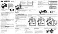
<strong>ICM</strong>401<br />
3-PHASE MONITOR<br />
The <strong>ICM</strong>401 is a low cost 3-<strong>phase</strong> line <strong>monitor</strong> that protects against <strong>phase</strong><br />
loss, <strong>phase</strong> reversal and <strong>phase</strong> unbalance. Ideally suited to protect scroll &<br />
screw compressors from reverse rotation.<br />
Features<br />
• Low cost, single side 3-<strong>phase</strong> protection<br />
• Bright LED indicators for fault and load energized<br />
• Easy to install, no adjustments<br />
• Wide operating range: 190-600 VAC<br />
• Less than 1-second <strong>phase</strong> loss response<br />
• Automatic reset from a fault condition<br />
• Compact packaging: fits almost anywhere<br />
• Rugged, epoxy-encapsulation for extreme<br />
conditions<br />
• Works great with the <strong>ICM</strong>450 for load side<br />
<strong>monitor</strong>ing of part winding start motors and<br />
multiple compressor systems<br />
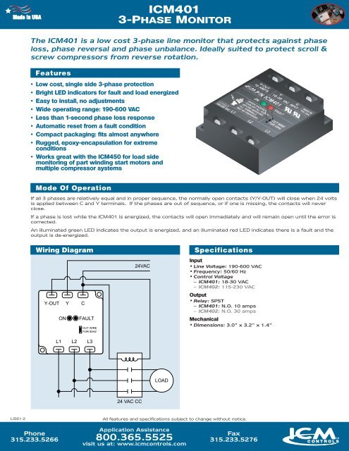
Mode Of Operation<br />
If all 3 <strong>phase</strong>s are relatively equal and in proper sequence, the normally open contacts (Y/Y-OUT) will close when 24 volts<br />
is applied between C and Y terminals. If the <strong>phase</strong>s are out of sequence, or if one is missing, the contacts will never<br />
close.<br />
If a <strong>phase</strong> is lost while the <strong>ICM</strong>401 is energized, the contacts will open immediately and will remain open until the error is<br />
corrected.<br />
An illuminated green LED indicates the output is energized, and an illuminated red LED indicates there is a fault and the<br />
output is de-energized.<br />
Wiring Diagram<br />
Specifications<br />
Input<br />
• Line Voltage: 190-600 VAC<br />
• Frequency: 50/60 Hz<br />
• Control Voltage<br />
– <strong>ICM</strong>401: 18-30 VAC<br />
– <strong>ICM</strong>402: 115-230 VAC<br />
Output<br />
• Relay: SPST<br />
– <strong>ICM</strong>401: N.O. 10 amps<br />
– <strong>ICM</strong>402: N.O. 30 amps<br />
Mechanical<br />
• Dimensions: 3.0” x 3.2” x 1.4”<br />
LIS61-2<br />
All features and specifications subject to change without notice.<br />
Phone<br />
315.233.5266<br />
Application Assistance<br />
800.365.5525<br />
visit us at: www.icmcontrols.com<br />
Fax<br />
315.233.5276
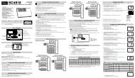
<strong>ICM</strong>401 Typical Wiring Diagram<br />
Contactor<br />
Compressor<br />
Transformer<br />
Thermostat<br />
Typical Part Winding Start Wiring Diagram with an <strong>ICM</strong>450 and <strong>ICM</strong>401<br />
Control Voltage Transformer<br />
0C<br />
0B<br />
0A<br />
Thermostat<br />
LINE<br />
0C<br />
LOAD<br />
0C<br />
LINE<br />
0B<br />
LOAD<br />
0B<br />
LINE<br />
0A<br />
<strong>ICM</strong>450<br />
LOAD<br />
0A<br />
1<br />
3<br />
4<br />
6<br />
Pressure<br />
Switch<br />
CC1<br />
Delay<br />
CC2<br />
Y Y-OUT<br />
L3<br />
24 VAC L2<br />
COM<br />
L1<br />
<strong>ICM</strong>401*<br />
Aux.<br />
NOTE:<br />
This diagram is also applicable to <strong>ICM</strong>400 with<br />
auto-man reset mode switch.<br />
* Use <strong>ICM</strong>401 for 24 VAC Control voltage only<br />
PWS motor with 3 -<strong>phase</strong> <strong>monitor</strong> and single side <strong>monitor</strong>