

Instruction Manual - Nature Coast Hobby Shop
Instruction Manual - Nature Coast Hobby Shop
Instruction Manual - Nature Coast Hobby Shop

You also want an ePaper? Increase the reach of your titles
YUMPU automatically turns print PDFs into web optimized ePapers that Google loves.
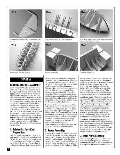
FIG. 1<br />
FIG. 3 FIG. 5<br />
A bulkhead marked and ready for assembly to the<br />
false keel.<br />
FIG. 2<br />
Deck plate mounting held with clothespins.<br />
FIG. 4<br />
Bow blocks shaped. Black line is black tape defining<br />
chamfered width of false keel.<br />
FIG. 6<br />
Bulkhead and false keel assembly.<br />
Bow blocks mounted.<br />
Stern blocks mounted.<br />
8<br />
STAGE A<br />
BUILDING THE HULL ASSEMBLY<br />
The Hull Assembly of any model represents<br />
75% of the job. Besides serving as<br />
the support platform for the masts and<br />
rigging, most attention given by the observer<br />
will be directed toward the hull<br />
lines and deck details. For these reasons,<br />
the hull framework should be constructed<br />
with precision, creating a sturdy, true<br />
and perfectly symmetrical showpiece.<br />
The Prince de Neufchatel hull frame is<br />
made up of 22 bulkheads, a one-piece<br />
false keel and a deck plate. They are all<br />
laser cut to close tolerances, allowing a fit<br />
that should not require any additional<br />
fixtures for alignment when properly assembled.<br />
Extensive use of horizontal waterlines<br />
and vertical centerlines on these<br />
parts are a great help in establishing<br />
what will be the basis for all subsequent<br />
construction.<br />
1. Bulkhead & False Keel<br />
Preparation:<br />
The bulkheads are cut from 1/8”-thick<br />
plywood and are sequentially identified<br />
“A” to “V” from bow to stern (see figure<br />
1). Each of them has shaped extensions<br />
above the deck line to define the height<br />
of the bulwarks and they are grooved to<br />
fit over the 3/16”-thick false keel piece.<br />
(Bulkhead “O” does not extend above the<br />
deck so as to prevent interference with<br />
the gunport openings.) The pre-cut bulkheads<br />
have the deck camber cut in.<br />
Check the keel grooves for an accurate fit<br />
over the false keel. If too small, they<br />
should be widened equally about the<br />
centerline. Before mounting to the keel,<br />
label and mark each bulkhead with a vertical<br />
centerline and a horizontal line perpendicular<br />
to the centerline and through<br />
the deck crown at the bulwarks.<br />
Next, check all bulkhead grooves of the<br />
3/16”-thick plywood false keel to ascertain<br />
that they will accept the 1/8”-thick<br />
bulkheads. The depth of the grooves<br />
should allow each bulkhead to sit with its<br />
center flush with the top of the false keel<br />
piece (see figure 2). Vertical lines should<br />
be drawn to establish bulkhead alignment<br />
on the keel piece at the forward<br />
side of each bulkhead groove.<br />
Note: all groove fits should be close, but<br />
not bind or allow excess movement.<br />
2. Frame Assembly:<br />
Starting from either the bow or stern, sequentially<br />
glue the bulkheads into place<br />
(see figure 2). The center of each bulkhead<br />
should be aligned with the center of<br />
the keel piece, and the horizontal line on<br />
each bulkhead must be set perpendicular<br />
to the vertical side of the keel piece. This<br />
can be checked with a small square. The<br />
bulkhead should also be at a 90-degree<br />
angle to the keel piece. Sequential mounting<br />
is necessary to allow use of the<br />
square for each bulkhead alignment.<br />
Bulkheads can be held with white glue<br />
and clamped with clothespins. When<br />
properly aligned, the joint can be set by<br />
wicking in slow-set cyanoacrylate glue.<br />
A note on glues: White glues are slower<br />
setting and tolerant to parts adjustments.<br />
They tend to fill wood porosity, and this,<br />
along with their moisture content, provides<br />
a stronger bond when an additional<br />
application of cyanoacrylate glue is<br />
combined (for joints that need it). For<br />
more delicate assembly work, this combination<br />
of glues is not recommended,<br />
since some filleting may occur and the<br />
white glue does not always dry clear.<br />
A note on hull symmetry: Eyeballing–<br />
Even though you have carefully marked<br />
and set each bulkhead square on the false<br />
keel, keep eyeing the entire assembly<br />
from stern to bow to assure that no twist<br />
has set in that would result in a warped<br />
deck or cocked transom mounting.<br />
3. Deck Plate Mounting:<br />
The sub-deck plate of 1/32”-thick laser<br />
cut aircraft grade plywood is the next<br />
item to be installed to the hull framework<br />
(see figure 3). Draw a centerline on the


