Regency IG34 owners & instal manual.pdf
Regency IG34 owners & instal manual.pdf
Regency IG34 owners & instal manual.pdf

Create successful ePaper yourself
Turn your PDF publications into a flip-book with our unique Google optimized e-Paper software.
Owners &<br />
Installation<br />
Manual<br />
LISTINGS AND CODE APPROVALS<br />
These gas appliances have been tested in<br />
accordance with AS4553, NZS 5262 and<br />
have been certifi ed by the Australian Gas<br />
Association for <strong>instal</strong>lation and operation as<br />
described in these Installation and Operating<br />
Instructions.<br />
Your unit should be serviced annually by<br />
an authorised service person.<br />
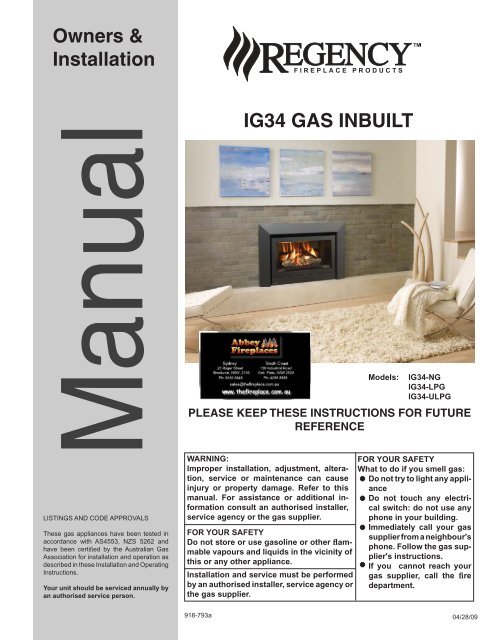
<strong>IG34</strong> GAS INBUILT<br />
Models:<br />
<strong>IG34</strong>-NG<br />
<strong>IG34</strong>-LPG<br />
<strong>IG34</strong>-ULPG<br />
PLEASE KEEP THESE INSTRUCTIONS FOR FUTURE<br />
REFERENCE<br />
WARNING:<br />
Improper <strong>instal</strong>lation, adjustment, alteration,<br />
service or maintenance can cause<br />
injury or property damage. Refer to this<br />
<strong>manual</strong>. For assistance or additional information<br />
consult an authorised <strong>instal</strong>ler,<br />
service agency or the gas supplier.<br />
FOR YOUR SAFETY<br />
Do not store or use gasoline or other flammable<br />
vapours and liquids in the vicinity of<br />
this or any other appliance.<br />
Installation and service must be performed<br />
by an authorised <strong>instal</strong>ler, service agency or<br />
the gas supplier.<br />
FOR YOUR SAFETY<br />
What to do if you smell gas:<br />
Do not try to light any appliance<br />
Do not touch any electrical<br />
switch: do not use any<br />
phone in your building.<br />
Immediately call your gas<br />
supplier from a neighbour's<br />
phone. Follow the gas supplier's<br />
instructions.<br />
If you cannot reach your<br />
gas supplier, call the fire<br />
department.<br />
918-793a<br />
04/28/09
REGENCY<br />
GAS INBUILT FIREPLACE<br />
TO THE NEW OWNER<br />
Congratulations! You are the owner of a state-of-the-art Gas Inbuilt Fireplace by FPI. The <strong>Regency</strong><br />
Gas Fireplace Series of appliances has been designed to provide you with all the warmth and<br />
charm of a fi replace, at the fl ick of a switch. The model <strong>IG34</strong> of this series has been approved<br />
by Australian Gas Association for both safety and efficiency. As it also bears our own mark, it<br />
promises to provide you with economy, comfort and security for many trouble free years to follow.<br />
Please take a moment now to acquaint yourself with these instructions and the many features of<br />
your <strong>Regency</strong> Fireplace.<br />
UNIT DIMENSIONS<br />
2 <strong>Regency</strong> <strong>IG34</strong> Gas Inbuilt Fireplace
TABLE OF CONTENTS<br />
DATA BADGE<br />
Copy of Data Badge .....................................................4<br />
INSTALLATION<br />
Important Message ........................................................5<br />
For Your Safety ..............................................................5<br />
Before You Start ............................................................5<br />
Installation Checklist ......................................................5<br />
Materials Required ........................................................5<br />
Minimum Fireplace Dimensions ....................................6<br />
Clearances To Combustibles .........................................6<br />
Gas Connection ............................................................6<br />
Flueing ...........................................................................6<br />
Flue Liner Installation ....................................................7<br />
Gas Pipe Pressure Testing ............................................7<br />
Installation in masonry or zero clearance chimney........8<br />
Aeration Settings ...........................................................9<br />
Conversion Kit #486-968 for NG to LPG Model ..........10<br />
Conversion Kit #486-967 for NG to ULPG...................12<br />
Optional Stainless steel inner panel <strong>instal</strong>l ..................14<br />
Log set <strong>instal</strong>lation .......................................................15<br />
Glass Door <strong>instal</strong>lation.................................................18<br />
Standard Flush Door ...................................................18<br />
Optional Flush Trim .........................................................<br />
Faceplate & Optional plinth trim Assembly ..................19<br />
Faceplate and door frame Installation .........................20<br />
Thermodisc <strong>instal</strong>lation ................................................21<br />
Final Check..................................................................22<br />
Wiring standard ...........................................................22<br />
Operating Instructions ................................................23<br />
Lighting Instructions.....................................................23<br />
Shutdown Instructions .................................................23<br />
First Fire ......................................................................23<br />
Remote Control ..........................................................23<br />
Summary of Controls ..................................................23<br />
Fan Operation..............................................................23<br />
Copy Of Lighting Instruction Plate ...............................24<br />
Normal Operating Sounds Of Gas Appliances ............24<br />
Resetting the unit.........................................................24<br />
MAINTENANCE<br />
Door Glass ..................................................................25<br />
Replacement ...............................................................25<br />
Glass Gasket ...............................................................25<br />
Fan Maintenance .........................................................26<br />
Valve assembly replacement .......................................27<br />
PARTS LIST<br />
Electronic Components Parts List ...............................28<br />
Main Assembly ............................................................29<br />
Faceplate Assembly ....................................................30<br />
WARRANTY<br />
Warranty ......................................................................31<br />
<strong>Regency</strong> <strong>IG34</strong> Gas Inbuilt Fireplace<br />
3
DATA BADGE<br />
This is a copy of the label that accompanies each <strong>Regency</strong> <strong>IG34</strong> Gas<br />
Inbuilt fi replace. We have printed a copy of the contents here for your<br />
review.<br />
Check the label on the unit and if there is a difference, the label on the<br />
unit is the correct one.<br />
DATA BADGE NOTE: <strong>Regency</strong> units are constantly being improved.<br />
<strong>Regency</strong> Gas Fireplace<br />
Model<br />
Gas Type NG LPG ULPG<br />
Model<br />
<strong>IG34</strong>-NG <strong>IG34</strong>-LPG <strong>IG34</strong>-ULPG<br />
Gas Consumption 31.7 mj. 30.6mj. 26.4mj.<br />
Manifold Pressure 0.87 kPa 2.51 kPa 2.51 kPa<br />
Injector Size 1x#<br />
37 1x#52 1x#53<br />
AGA Approval 7469<br />
Code AS4553 NZS 5262<br />
2.64mm 1.61mm 1.51mm<br />
Distributed by:<br />
Western Australia:<br />
Air Group Australia<br />
28 Division St<br />
Welshpool WA 6106<br />
Eastern Australia:<br />
Fireplace Products<br />
Australia Pty. Ltd.<br />
21-23 South Link Blvd.<br />
Dandenong, VIC 3175<br />
To be <strong>instal</strong>led by an authorised person in<br />
accordance with <strong>instal</strong>lation instructions provided<br />
with the appliance.<br />
Electrical: 240VAC 50Hz 1.0 amp<br />
N2134<br />
Serial<br />
Number<br />
347<br />
918-794<br />
(Australia Only)<br />
4 <strong>Regency</strong> <strong>IG34</strong> Gas Inbuilt Fireplace
INSTALLATION<br />
IMPORTANT MESSAGE<br />
The <strong>Regency</strong> Gas Inbuilt must be <strong>instal</strong>led in<br />
accordance with these instructions. Carefully<br />
read all the instructions in this <strong>manual</strong> fi rst.<br />
Note: Failure to follow these instructions<br />
could cause a malfunction of the<br />
heater which could result in death,<br />
serious bodily injury, and/or property<br />
damage. Failure to follow these<br />
instructions may also void your fire<br />
insurance and/or warranty.<br />
FOR YOUR SAFETY<br />
This appliance requires air for proper combustion.<br />
Always provide adequate combustion<br />
and ventilation air. Follow instructions and<br />
information in the current AS5601, NZS 5262<br />
or local codes. Consult the "authority having<br />
jurisdiction" to determine the need for a permit<br />
prior to starting the <strong>instal</strong>lation.<br />
MATERIALS REQUIRED<br />
A 240 Volt AC power cord is hooked up to the<br />
unit. Plug 3 wire cord into a suitable receptacle.<br />
Do not cut the ground terminal off under any<br />
circumstances.<br />
When connected with 240 volts, the appliance<br />
must be electrically grounded in accordance<br />
with local codes.<br />
This unit is polarity sensitive and will not<br />
operate if polarity is incorrect.<br />
WARNING:<br />
Suitable for <strong>instal</strong>lation into a masonry<br />
fi replace only.<br />
BEFORE YOU START<br />
Installation is to be carried out ONLY by an<br />
authorised person.<br />
1) The appliance shall be <strong>instal</strong>led in accordance<br />
with the manufacturer's <strong>instal</strong>lation<br />
instructions, local gas fi tting regulations,<br />
municipal building codes, water supply<br />
regulations, electrical wiring regulations,<br />
with AS5601. (AGA gas <strong>instal</strong>lation code)<br />
NZS 5262(New Zealand)<br />
2) Installation and repair should be done<br />
ONLY by an authorised person.<br />
3) The appliance should be inspected before<br />
use and at least annually by an authorised<br />
service person. More frequent cleaning may<br />
be required due to excessive lint from carpeting,<br />
bedding material, etc. It is imperative<br />
that control compartments, burners and<br />
circulating air passageways of the appliance<br />
be kept clean and free from excessive lint<br />
from carpeting.<br />
4) See general construction and assembly<br />
instructions. This appliance may only be <strong>instal</strong>led<br />
in a flued, non-combustible fireplace.<br />
The appliance and fl ue should be enclosed<br />
when <strong>instal</strong>led or passing through a living<br />
area, where children may come in contact<br />
with it.<br />
5) Always connect this space heater to a chimney<br />
and fl ue to the outside of the building<br />
envelope. Never flue to another room. Make<br />
sure that the fl ue is properly sized and is<br />
of adequate height to provide the proper<br />
draft.<br />
6) Inspect the fl ueing system annually for<br />
blockage and any signs of deterioration.<br />
7) Any safety glass removed for servicing<br />
must be replaced prior to operating the appliance.<br />
8) To prevent injury, do not allow anyone who<br />
is unfamiliar with the operation to use the<br />
fi replace.<br />
9) Installer must mechanically attach the supplied<br />
label to the inside of the fi rebox of the<br />
fi replace into which the gas fi replace insert<br />
is <strong>instal</strong>led.<br />
"WARNING: This fireplace has been converted<br />
for use with a gas fi replace insert only and<br />
cannot be used for burning wood or solid fuels<br />
unless all original parts have been replaced,<br />
and the fi replace re-approved by the authority<br />
having jurisdiction."<br />
INSTALLATION<br />
CHECKLIST<br />
Before <strong>instal</strong>ling vent system ensure that the<br />
damper plate is open and secure to prevent the<br />
damper plate from falling down and crushing<br />
the liner.<br />
The FPI Gas Inbuilt is <strong>instal</strong>led as listed.<br />
1) Check all clearances to combustibles, (Refer<br />
to sections "Minimum Fireplace Dimensions<br />
and Clearances to Combustibles)<br />
2) Make the gas connection. (Refer to section<br />
"Gas Connection")<br />
3) Install the 3" (76.2mm) flue liner to the sliding<br />
connector plate. (Refer to section "Flue Liner<br />
Installation.")<br />
4) Slide the unit half way into the fi replace.<br />
5) Pull the vent connector plate through the<br />
tapered brackets and fasten to the front plate.<br />
Refer to section "Flue Liner Installation.")<br />
6) Slide the unit fully into the fi replace.<br />
7) Test gas pressure (Refer to section "Gas<br />
Pipe Pressure Testing"). Check aeration<br />
system (Refer to section "Gas Insert Aeration<br />
System").<br />
8) Install standard and optional features. Refer<br />
to the following sections:<br />
a. Log Set<br />
b. Faceplate & Door Trim<br />
c. Inner Stainless Panels<br />
9) Final check: Before leaving this unit with the<br />
customer, the <strong>instal</strong>ler must ensure that the<br />
appliance is fi ring correctly. This includes:<br />
a) Clocking the appliance to ensure the<br />
correct fi ring rate.<br />
b) Adjusting the primary air and restrictor<br />
settings, if required, to ensure that the<br />
fl ame does not carbon.<br />
NOTE:<br />
TO BE INSTALLED ON A<br />
NON- COMBUSTIBLE FLOOR.<br />
<strong>Regency</strong> <strong>IG34</strong> Gas Inbuilt Fireplace<br />
5
INSTALLATION<br />
MINIMUM FIREPLACE<br />
DIMENSIONS<br />
The minimum fi replace dimensions for the<br />
<strong>Regency</strong> gas space heater are shown in the<br />
following diagrams:<br />
Mantel Clearances<br />
FLUEING<br />
THE APPLIANCE MUST NOT<br />
BE CONNECTED TO A<br />
CHIMNEY FLUE SERVING A<br />
SEPARATE SOLID FUEL<br />
BURNING APPLIANCE AND<br />
MUST BE TERMINATED TO<br />
THE OUTDOORS.<br />
CLEARANCES TO<br />
COMBUSTIBLES<br />
Minimum Clearances to Combustibles<br />
From Unit<br />
Sides A 10" / 255mm<br />
Ceiling B 47.5" / 1205mm<br />
Mantel C 13" / 330mm<br />
Max. Mantle Depth E 12" / 305mm<br />
(see Dia. 2)<br />
Min. Alcove Width F 48" / 1220 mm<br />
Max. Alcove Depth G 36" / 915 mm<br />
*No hearth required.<br />
Note: A non-combustible mantel may be<br />
<strong>instal</strong>led at a lower height if the framing<br />
is made of metal studs covered<br />
with a non-combustible board.<br />
GAS CONNECTION<br />
GAS CONNECTION WARNING:<br />
Only persons licensed to work<br />
with gas piping may make the<br />
necessary gas connections<br />
to this appliance.<br />
1) If the appliance is to be <strong>instal</strong>led into an<br />
existing chimney system, thoroughly clean<br />
the masonry fi replace.<br />
2) The appliance is provided with an opening<br />
on the right hand side of the control<br />
compartment. The 9.5mm (3/8") fl exible<br />
gas hose provided needs to be brought in<br />
from behind this opening. Ensure all gas<br />
connections are tight.<br />
3) Locate the center point where the vent<br />
will pass through the chimney above the<br />
appliance. Move the appliance into the<br />
exact location where it is to be <strong>instal</strong>led.<br />
Ensure that the Insert is level.<br />
This appliance is designed to be attached to<br />
two 3" (76mm) co-linear aluminium fl ex running<br />
the full length of the chimney. The fl ue length<br />
must be a minimum length of 8 ' (2.44m) and<br />
a maximum of 35' (10.7m). See chart below for<br />
minimum distances from roof. Periodically check<br />
that the vent is unrestricted.<br />
Masonry chimneys may take various contours<br />
which the fl exible liner will accommodate.<br />
However, keep the flexible liner as straight as<br />
possible, avoid unnecessary bending.<br />
The Air Intake pipe must be attached to the inlet<br />
air collar of the termination cap.<br />
Part # Description<br />
948-305 76mm Flex - 10.6m<br />
46dva-gk Simpson Duravent Adaptor<br />
46dva-vch Simpson Vertical high wind cap<br />
C L<br />
Gas<br />
Inlet<br />
Note:<br />
When <strong>instal</strong>ling the fl ueing, identify<br />
the fl ues.<br />
Mark one exhaust and one intake as<br />
indicated on the top of the unit.<br />
6 <strong>Regency</strong> <strong>IG34</strong> Gas Inbuilt Fireplace
INSTALLATION<br />
The Air Intake pipe must be attached to the<br />
inlet air collar of the termination cap.<br />
4) Seal and or check the pilot outlet (# 8)<br />
5) The pressure check should be carried out<br />
with the unit burning and the setting should<br />
be within the limits specifi ed on the safety<br />
label.<br />
6) When fi nished reading manometer, turn<br />
off the gas valve, disconnect the hose and<br />
tighten the screw (clockwise) with a 1/8"<br />
fl at screwdriver. Screw should be snug,<br />
but do not over tighten.<br />
FLUE LINER<br />
INSTALLATION<br />
1) Cut the fl ex liner as required.<br />
2) Mark the end of one liner to indicate<br />
Inlet.<br />
3) Connect the other end of the above liner to<br />
the inlet side of the termination adaptor, seal<br />
connection with high temperature silicone.<br />
Secure with gear clamp.<br />
4) Connect the 2nd liner to the exhaust side<br />
of the adaptor, seal connection with high<br />
temperature silicone. Secure with gear<br />
clamp.<br />
Be careful not to damage thermal insulation<br />
when sliding on vent connector plate.<br />
This could cause blockage.<br />
9) Connect the 2nd liner to the exhaust collar<br />
marked with an "E", seal connection with<br />
high temperature silicone. Secure with gear<br />
clamp.<br />
S.I.T. Valve Description<br />
1) On-Off Solenoid Valve EV1<br />
2) On-Off Solenoid Valve EV2<br />
3) Inlet Pressure Test Point<br />
4) Outlet Pressure Test Point<br />
5) Connection for Pressure Regulator/<br />
Combustion Chamber Compensation<br />
6) Pressure Regulator for Minimum and<br />
Maximum Outlet Pressure<br />
7) Gas Outlet Pressure Electric Modulator<br />
8) Pilot Outlet<br />
9) Main Gas Outlet<br />
10) Side Outlet<br />
GAS PIPE PRESSURE<br />
TESTING<br />
The appliance must be isolated from the gas<br />
supply piping system by closing its individual<br />
<strong>manual</strong> shut-off valve during any pressure<br />
testing of the gas supply piping system at<br />
test pressures equal to or less than 1/2 psig.<br />
(3.45 kPa). Disconnect piping from valve at<br />
pressures over 3.45 kPa (14" w.c.).<br />
The manifold pressure is controlled by a<br />
regulator built into the gas control, and should<br />
be checked at the pressure test point.<br />
5) Install fl ashing.<br />
6) Insert both liners into chimney, passing<br />
through the damper opening.<br />
Note:<br />
To properly check gas pressure,<br />
both inlet and manifold pressures<br />
should be checked using the valve<br />
pressure ports on the valve.<br />
7) Install termination cap.<br />
8) Connect the marked end of the liner to the inlet<br />
collar of the vent connector plate marked with<br />
an "I", seal connection with high temperature<br />
silicone. Secure with gear clamp.<br />
Install to AS5601 (Australia) /<br />
NZS 5262 (New Zealand)<br />
1) Make sure the valve is in the "OFF"<br />
position.<br />
2) Loosen the "IN" (# 3) and/or "OUT" (# 4)<br />
pressure tap(s), turning counterclockwise<br />
with a 1/8" wide flat screwdriver.<br />
3) Attach manometer to "IN" and/or "OUT"<br />
pressure tap(s) using a 5/16" (8mm) ID<br />
hose.<br />
<strong>Regency</strong> <strong>IG34</strong> Gas Inbuilt Fireplace<br />
7
INSTALLATION<br />
INSTALLATION IN MASONRY OR ZERO CLEARANCE CHIMNEY<br />
1) Measure and record dimensions to determine total<br />
Flex Liner length requirements (see instructions below<br />
for details).<br />
2) Carefully feed the liner down the chimney (masonry<br />
or zero clearance) and out through the damper. One<br />
person should feed the liner through the chimney, and<br />
another person should pull the liner from the bottom.<br />
3) After carefully feeding the Flex Liner down the chimney<br />
to the bottom, form and angle to line up the Flex<br />
Liner with the vent opening on the appliance.<br />
Important: Do not let the Flex Liner sag below the level<br />
at which it will connect to the appliance or connector.<br />
This could allow hot gas to become trapped and potentially<br />
become a fi re hazard. The Flex Liner path should<br />
always be sloped up toward the Termination Cap.<br />
Note: If you are planning to extend the height of the<br />
chimney using Direct Vent GS Pipe, please refer to the<br />
Direct Vent Installation Instructions for information concerning<br />
the proper procedure and restrictions of Direct<br />
Vent Pipe.<br />
Also, consult the appliance manufacturer for any height<br />
restrictions of the chimney.<br />
9) Connect the Co-Linear Flex to the two outlets on the<br />
top of the appliance using four sheet metal screws each.<br />
See the appliance manufacturer's instructions for details.<br />
Make sure the Flex Liners do not sag behind the<br />
appliance. Finally, move the appliance into its appropriate<br />
place. Mount the Adaptor to the Baseplate using<br />
sheet metal screws.<br />
4) Temporarily secure the Flex Liner at the top of the<br />
chimney. Be sure to leave 2-3 inches of fl ex above the<br />
existing chimney to allow for connection to the Termination<br />
Kit (Baseplate and Adaptor).<br />
Flex<br />
Liners<br />
51-76mm<br />
Existing<br />
Chimney<br />
5) Repeat Steps 1-4 for second length of Flex Liner.<br />
6) At the top of the chimney, slide the Baseplate over<br />
the tow ends of the Flex Liner and secure it to the surrounding<br />
masonry using masonry anchor bolts. Before<br />
<strong>instal</strong>ling the baseplate, run a bead of non-hardening<br />
seal and between the Baseplate and the masonry to<br />
prevent moisture from entering the chimney.<br />
Note: Verify that there is suffi cient room to mount the<br />
Baseplate on to the masonry. You must have a level<br />
surface in order to <strong>instal</strong>l the Baseplate properly.<br />
7) Attach the Flex Liner ends at the top of the chimney<br />
to the Co-Linear to Co-Axial Adaptor. Use four sheet<br />
metal screws to connect each Flex Liner run to the<br />
Adaptor.<br />
8) Twist lock the Vertical Termination Cap to the Adaptor.<br />
8 <strong>Regency</strong> <strong>IG34</strong> Gas Inbuilt Fireplace
INSTALLATION<br />
System Data<br />
<strong>IG34</strong><br />
<strong>IG34</strong>-NG: For 0 to 610 meters altitude<br />
<strong>IG34</strong>-LPG: For 0 to 610 meters altitude<br />
<strong>IG34</strong>-ULPG: For 0 to 610 meters altitude<br />
Burner Inlet Orifi ce Sizes:<br />
NG LPG ULPG<br />
Burner #37 #52 #53<br />
Max. Input<br />
NG<br />
LPG<br />
ULPG<br />
Min. Input<br />
NG<br />
LPG<br />
ULPG<br />
Supply Pressure<br />
NG<br />
LPG<br />
ULPG<br />
31.7 mj<br />
30.6 mj<br />
26.4 mj<br />
21.1 mj<br />
25.1 mj<br />
20.9 mj<br />
1.13 kPa<br />
2.75 kPa<br />
2.75 kPa<br />
Manifold Pressure HIGH LOW<br />
NG 0.87 kPa 0.4kPa<br />
LPG 2.51 kPa 1.6kPa<br />
ULPG 2.51 kPa 1.6kPa<br />
Electrical: 240 V. 50Hz.<br />
Circulation: High/Off/LO speed fan,<br />
150/89 CFM.<br />
Log Set: Ceramic fi ber, 7 per set.<br />
Aeration Setting<br />
NG 13mm open<br />
LPG 13mm open<br />
ULPG 13mm open<br />
AERATION SETTINGS<br />
The burner aeration is factory set but may need adjusting due to either the local gas supply, air supply or altitude. This adjustment is performed by<br />
the <strong>instal</strong>ler. (Close the aeration for a more yellow fl ame, or open it to make the fl ame bluer).<br />
NG: 13mm open<br />
LPG: 13mm open<br />
ULPG: 13mm open<br />
Note: Any damage due to carboning resulting from improperly setting the aeration and restrictor setting controls is NOT covered<br />
under warranty.<br />
<strong>Regency</strong> <strong>IG34</strong> Gas Inbuilt Fireplace<br />
9
INSTALLATION<br />
Conversion Kit #486-968 for NG to LPG Model<br />
THIS CONVERSION MUST BE DONE BY A QUALIFIED GAS FITTER<br />
IF IN DOUBT DO NOT DO THIS CONVERSION !!<br />
Conversion Kit 486-968 Contains:<br />
Qty. Part # Description<br />
1 904-345 Burner Orifi ce #51<br />
1 918-273 Red "LPG" label<br />
1 918-272 Label "Converted to LPG"<br />
1 910-037 LPG Pilot Injector<br />
1 918-823 Instruction Sheet<br />
1) Shut off the gas supply and unplug<br />
the power cord.<br />
2) Remove the glass door, logs and<br />
lava rock.<br />
3) Remove the rear log tray by removing<br />
the 2 screws. (Log tray must be<br />
rotated to clear the burner.)<br />
4) Remove the grate.<br />
5) Remove the burner and ensure the<br />
aeration setting is 13 mm open.<br />
6) Remove burner orifi ce with a 1/2"<br />
wrench and discard. Use a wrench<br />
to hold on to the elbow behind the<br />
orifi ce.<br />
9) Pull out the pilot hood by hand.<br />
Pilot<br />
Hood<br />
Pilot<br />
Hood<br />
removed<br />
Pilot<br />
Orifi ce<br />
10) Remove the pilot orifi ce with the<br />
allen key.<br />
12) Replace the yellow "NG" label with<br />
the red "ULPG" label.<br />
13) Carefully pull out the control box.<br />
NOTE: The control box is held in<br />
place with velcro.<br />
14) Remove the heat shield from the<br />
control box by removing the 2<br />
screws.<br />
15) Remove the control box cover by<br />
undoing the 3 screws.<br />
Manoeuvre through antenna.<br />
Antenna<br />
Control Box<br />
Cover<br />
16) Remove the jumper using a plier.<br />
Burner<br />
11) Put in the new LPG orifi ce with the<br />
allen key. Then put back the pilot<br />
hood.<br />
Jumper Location<br />
7) Re<strong>instal</strong>l new burner orifi ce LPG<br />
stamped #51 and tighten.<br />
8) Apply the conversion label "This<br />
unit has been converted to ULPG"<br />
over top of the serial number decal.<br />
Jumper<br />
Note: Aeration settings do not need<br />
to be adjusted.<br />
17) Reverse steps 13, 12, 11, 6, 5, 4, 3<br />
& 2.<br />
10 <strong>Regency</strong> <strong>IG34</strong> Gas Inbuilt Fireplace
INSTALLATION<br />
18) Turn on gas supply and plug in power cord.<br />
19) Adjusting the Outlet Pressure<br />
All the adjustments must be<br />
carried out in the following order:<br />
Remove the modulator plastic cap (A) using needle nose<br />
pliers.<br />
After carrying out all adjustments, block the setting screws<br />
with paint, taking care not to obstruct the breather orifi ce<br />
of the pressure.<br />
Put back the modulator plastic cap.<br />
WARNING: To ensure the correct operation of the modulator<br />
it is necessary that the plastic cap (A) is returned to<br />
its original location.<br />
Maximum pressure: Turn the unit ON to its highest input<br />
rating. Screw in the nut (B) to increase the outlet pressure<br />
and screw it out to decrease it. Use a 10 mm wrench.<br />
NOTE: The outlet pressure must be set to maximum 2.51<br />
kPa.<br />
B<br />
A<br />
C<br />
Minimum pressure: Remove one of the cables connected<br />
to the electric modulator. While holding the nut (B) with<br />
a wrench, screw in the screw (C) to increase the pressure<br />
and screw it out to decrease it. Use a screwdriver 6 x 1<br />
blade.<br />
NOTE: The outlet pressure must be set to minimum 1.6<br />
kPa.<br />
Cable<br />
Electric<br />
Modulator<br />
20) Turn on gas supply and plug in power cord.<br />
21) At the end of all setting and adjustment operations, check<br />
electrical <strong>instal</strong>lation and gas leaks.<br />
22) Check operation of fl ame control.<br />
23) Check for proper fl ame appearance and glow on logs.<br />
Installer Notice:<br />
These instructions must be left<br />
with the appliance.<br />
<strong>Regency</strong> <strong>IG34</strong> Gas Inbuilt Fireplace<br />
11
INSTALLATION<br />
Conversion Kit #486-967 for NG to ULPG<br />
THIS CONVERSION MUST BE DONE BY A QUALIFIED GAS FITTER<br />
IF IN DOUBT DO NOT DO THIS CONVERSION !!<br />
Conversion Kit 486-967 Contains:<br />
Qty. Part # Description<br />
1 904-345 Burner Orifi ce #53<br />
1 918-273 Red "ULPG" label<br />
1 918-272 Label "Converted to ULPG"<br />
1 910-037 LPG Pilot Injector<br />
1 918-824 Instruction Sheet<br />
1) Shut off the gas supply and unplug<br />
the power cord.<br />
2) Remove the glass door, logs and<br />
lava rock.<br />
3) Remove the rear log tray by removing<br />
the 2 screws. (Log tray must be<br />
rotated to clear the burner.)<br />
4) Remove the grate.<br />
5) Remove the burner and ensure the<br />
aeration setting is 13 mm open.<br />
6) Remove burner orifi ce with a 1/2"<br />
wrench and discard. Use a wrench<br />
to hold on to the elbow behind the<br />
orifi ce.<br />
9) Pull out the pilot hood by hand.<br />
Pilot<br />
Hood<br />
Pilot<br />
Hood<br />
removed<br />
Pilot<br />
Orifi ce<br />
10) Remove the pilot orifi ce with the<br />
allen key.<br />
12) Replace the yellow "NG" label with<br />
the red "ULPG" label.<br />
13) Carefully pull out the control box.<br />
NOTE: The control box is held in<br />
place with velcro.<br />
14) Remove the heat shield from the<br />
control box by removing the 2<br />
screws.<br />
15) Remove the control box cover by<br />
undoing the 3 screws.<br />
Maneuver through antenna.<br />
Antenna<br />
Control Box<br />
Cover<br />
16) Remove the jumper using a plier.<br />
Burner<br />
11) Put in the new LPG orifi ce with the<br />
allen key. Then put back the pilot<br />
hood.<br />
Jumper Location<br />
7) Re<strong>instal</strong>l new burner orifi ce ULPG<br />
stamped #53 and tighten.<br />
8) Apply the conversion label "This<br />
unit has been converted to ULPG"<br />
over top of the serial number decal.<br />
Jumper<br />
Note: Aeration settings do not need<br />
to be adjusted.<br />
17) Reverse steps 13, 12, 11, 6, 5, 4, 3<br />
& 2.<br />
12 <strong>Regency</strong> <strong>IG34</strong> Gas Inbuilt Fireplace
INSTALLATION<br />
18) Turn on gas supply and plug in power cord.<br />
19) Adjusting the Outlet Pressure<br />
All the adjustments must be<br />
carried out in the following order:<br />
Remove the modulator plastic cap (A) using needle nose<br />
pliers.<br />
Maximum pressure: Turn the unit ON to its highest input<br />
rating. Screw in the nut (B) to increase the outlet pressure<br />
and screw it out to decrease it. Use a 10 mm wrench.<br />
After carrying out all adjustments, block the setting screws<br />
with paint, taking care not to obstruct the breather orifi ce<br />
of the pressure.<br />
Put back the modulator plastic cap.<br />
WARNING: To ensure the correct operation of the modulator<br />
it is necessary that the plastic cap (A) is returned to<br />
its original location.<br />
NOTE: The outlet pressure must be set to maximum 2.51<br />
kPa.<br />
B<br />
A<br />
C<br />
Minimum pressure: Remove one of the cables connected<br />
to the electric modulator. While holding the nut (B) with<br />
a wrench, screw in the screw (C) to increase the pressure<br />
and screw it out to decrease it. Use a screwdriver 6 x 1<br />
blade.<br />
NOTE: The outlet pressure must be set to minimum 1.6<br />
kPa.<br />
Cable<br />
Electric<br />
Modulator<br />
20) Turn on gas supply and plug in power cord.<br />
21) At the end of all setting and adjustment operations, check<br />
electrical <strong>instal</strong>lation and gas leaks.<br />
22) Check operation of fl ame control.<br />
23) Check for proper fl ame appearance and glow on logs.<br />
Installer Notice:<br />
These instructions must be left<br />
with the appliance.<br />
<strong>Regency</strong> <strong>IG34</strong> Gas Inbuilt Fireplace<br />
13
INSTALLATION<br />
OPTIONAL STAINLESS STEEL INNER PANEL INSTALL<br />
Before you start:<br />
Stainless panels must be inspected for scratches and dimples prior to <strong>instal</strong>lation. All claims to be recorded at this time. Claims for<br />
damage after <strong>instal</strong>lation will not receive consideration.<br />
To protect the finish during <strong>instal</strong>lation and handling - cotton gloves MUST be worn at all times while handling the panels (even<br />
when removing protective coating).<br />
Stainless panels will discolor a little during normal operation. This is normal and should not be considered a defect.<br />
All hand and fi nger marks MUST be cleaned off with a soft cloth and a stainless steel cleaner. Most stainless steel cleaners leave a<br />
fi lm/residue on the surface of the panels. Use an ammonia based cleaner (ie. glass cleaner) to remove this fi lm before applying heat to<br />
the unit. Failure to do this will result in burn stains on panels which you will be unable to remove. This is not a warranty item.<br />
1) Remove faceplate, inner door frame and screen if<br />
already <strong>instal</strong>led. Refer to page 18 in the instruction <strong>manual</strong>.<br />
6) Remove the two side brackets and screws (set aside) - then<br />
remove the side panels by tilting the top in and lifting them out.<br />
2) Remove the glass door by undoing 2 latches - lift up and out.<br />
Refer to page 17 in the <strong>manual</strong> for detailed instructions.<br />
3) Remove all the logs if <strong>instal</strong>led and set aside carefully.<br />
7) Orient the stainless side panels with the larger fold in the<br />
panel facing in towards the burner and facing the back of the<br />
firebox.<br />
4) Loosen the 4 screws securing the brackets that hold the existing<br />
back and side panels in place.<br />
Larger fold in the<br />
metal.<br />
5) Remove the two back brackets and screws (set aside) fi rst, then<br />
remove the back panel by lifting it up slightly, tilt it forward,<br />
then lift it out.<br />
8) Secure the stainless panel with original bracket and screw - repeat<br />
procedure on the opposite side.<br />
9) Re<strong>instal</strong>l the (original black) back panel - secure with 2 brackets<br />
and 2 screws (ones that were removed initially).<br />
10) Re<strong>instal</strong>l the logs, glass door, inner door frame with screen<br />
and finally the faceplate. See <strong>manual</strong> for detailed instructions.<br />
Final <strong>instal</strong>lation of optional stainless panels.<br />
14 <strong>Regency</strong> <strong>IG34</strong> Gas Inbuilt Fireplace
INSTALLATION<br />
LOG SET INSTALLATION<br />
Read the instructions below carefully and refer to the diagrams. If logs are broken do not use the unit until<br />
they are replaced. Broken logs can interfere with the pilot operation.<br />
The gas log kit contains the following:<br />
a) 02-43 Rear Log<br />
b) 02-45 Front Right Log<br />
c) 02-56 Middle Left Log<br />
d) 02-46 Left Top Log<br />
e) 02-47 Center Log<br />
f) 02-48 Middle Right Log<br />
g) 02-44 Front Left Log<br />
h) 902-154 Embers<br />
i) 902-153 Rockwool<br />
j) 902-179/P Vermiculite<br />
k) 946-669 Platinum Embers<br />
(supplied with packaged <strong>manual</strong>)<br />
Vermiculite<br />
and embers<br />
Vermiculite<br />
and embers<br />
Vermiculite<br />
and embers<br />
3) Place Rear Log A)02-43 on the two pins on the rear<br />
log support.<br />
A)02-43<br />
Pins on Rear Log Support<br />
The "02" refer numbers (i.e. 02-43) are<br />
molded into the rear of each log.<br />
Note: Install Optional Brick Panels prior to <strong>instal</strong>ling logs.<br />
4) Place Front Right Log B)02-45 on the two pins as<br />
shown.<br />
1) Carefully remove the logs from the box and unwrap<br />
them. The logs are fragile, handle with care - do not<br />
force into position.<br />
2) Sprinkle the vermiculite around the fi rebox base. Take<br />
some of the embers (approx. 1/3 of the bag) and<br />
sprinkle over the vermiculite.<br />
B)02-45<br />
<strong>Regency</strong> <strong>IG34</strong> Gas Inbuilt Fireplace<br />
15
INSTALLATION<br />
5) Place the Middle Left Log C)02-56 on the two pins as<br />
shown.<br />
7) Place the notch in Center Log E)02-47 over Log B)02-<br />
45 and across the cutout on Log A)02-43.<br />
E)02-47<br />
A)02-43<br />
C)02-56<br />
B)02-45<br />
Notch<br />
Cutout<br />
Logs A)02-43, C)02-56, and B)02-45 in position<br />
Logs D)02-46 and E)02-47 in position.<br />
6) Place the Left Top Log D)02-46 on the pin on Log<br />
C)02-56 and on top of the cutout on Log A)02-43.<br />
8) Position notch in Front Right Log F)02-48 on Log<br />
E)02-47 and push the bottom right edge against the<br />
bracket on the burner tray and the front edge of the<br />
rear burner.<br />
Notch<br />
D)02-46<br />
A)02-43<br />
F)02-48<br />
C)02-56<br />
E)02-47<br />
Bracket<br />
Pin<br />
Cutout<br />
B)02-45<br />
16 <strong>Regency</strong> <strong>IG34</strong> Gas Inbuilt Fireplace
INSTALLATION<br />
B)02-45<br />
F)02-48<br />
Front edge of<br />
rear burner<br />
A)02-43<br />
10) Place the embers and Rockwool on the exposed front<br />
burner tray.<br />
Side View<br />
Bracket<br />
The bottom right edge of Log F)02-48 must sit snugly against<br />
the bracket and the front edge of the rear burner.<br />
9) Place Front Left Log G)02-44 onto the 2 front pins as<br />
shown.<br />
11) Separate platinum embers and place on and around<br />
the embers and rockwool on the burner tray. Avoid<br />
stacking platinum embers.<br />
12) Test fi re to ensure proper light off (make sure fl ame<br />
fl ows smoothly from one end of burner to the other. If<br />
there is any fl ame hesitation, check that area for any<br />
blockage of the burner port.<br />
G)02-44<br />
A) 02-43 D) 02-46 G) 02-48<br />
C) 02-44 B) 02-56 F) 02-47 E) 02-45<br />
The "02" refer numbers (i.e. 02-43) are<br />
molded into the rear of each log.<br />
<strong>Regency</strong> <strong>IG34</strong> Gas Inbuilt Fireplace<br />
17
INSTALLATION<br />
STANDARD FLUSH DOOR<br />
The standard flush door comes with a black frame. To <strong>instal</strong>l the frame<br />
and glass door, simply hook the top door fl ange onto the top of the unit<br />
and swing the door towards the unit, diagram 1. Be careful that the glass<br />
gasket does not roll up; there must be a gap between the gasket and the<br />
door lip to ensure that the door sits securely on the unit. See Diagram 2.<br />
GLASS DOOR INSTALLATION<br />
Diagram 1<br />
Diagram 2<br />
Use the hook to pull the spring out until you can put the hook<br />
into the slot on the bottom door bracket. Repeat for 2nd spring.<br />
See diagram 3.<br />
To remove the fl ush door, reverse the above steps.<br />
Diagram 3<br />
To remove the fl ush door, reverse the above steps.<br />
18 <strong>Regency</strong> <strong>IG34</strong> Gas Inbuilt Fireplace
FACEPLATE & OPTIONAL PLINTH TRIM ASSEMBLY<br />
1) Lay the faceplate panels fl at, face down on something soft so they don't scratch.<br />
2) Take the top faceplate and align the holes in it with the holes in the side panels.<br />
Secure with provided nuts and bolts.<br />
INSTALLATION<br />
<strong>IG34</strong> Faceplate Assembly / Plinth<br />
1 336-914 Faceplate / Trim Kit<br />
1 366-942 Plinth Kit (optional)<br />
1 336-016 Mesh Screen Door<br />
1 336-072F Mesh Bottom Screen<br />
6 904-576 #8 Phillips pan head screws<br />
1 336-012 Bottom Door<br />
Plinth Trim Option:<br />
Plinth Trim Kits are an option that can be used to finish off the <strong>instal</strong>lation when the bottom of the fireplace is higher than the<br />
hearth or to raise the fireplace.<br />
1) Lay the faceplate side panels flat, face down on something soft so they don't scratch.<br />
2) Attach the Plinth Trim to the bottom of the faceplate side panels with the screws provided.<br />
3) Install faceplate on unit - see next page.<br />
SCREEN INSTALLATION<br />
1) Hook the screen over the top of the door frame - lower until<br />
screen is flush with the door frame.<br />
2) Flip door frame and screen over - locate the bracket tab at<br />
the bottom of the door frame - fold the tab over 90º to secure<br />
the screen in place.<br />
3) Install screen and door frame on to unit - follow directions<br />
on next page.<br />
<strong>Regency</strong> <strong>IG34</strong> Gas Inbuilt Fireplace<br />
19
INSTALLATION<br />
FACEPLATE AND DOOR FRAME INSTALLATION<br />
1) Position faceplate on unit lining up screw holes on<br />
faceplate with screw holes on unit - secure with 4 screws.<br />
4) Push both bottom frame hinges down on the metal lip until<br />
they are fully seated.<br />
5) Flip bottom louver up to close.<br />
2) Install lower screw below glass door - secure with 4 screws.<br />
Note: Ensure that the fl anges on the sides of the fi rebox<br />
are on the outside, when <strong>instal</strong>ling the faceplate<br />
(see below).<br />
6) Install the door frame by hooking the top fl ange over the<br />
top of the glass door.<br />
Faceplate<br />
Flange on fi rebox<br />
3) Fold down the 2 hinges on the bottom frame to a fl at<br />
position.<br />
The bottom frame is <strong>instal</strong>led with a friction fi t - the<br />
opening in the corner of each hinge slides over the<br />
metal lip located on the fl oor of the unit.<br />
Note: Ensure the bottom frame is positioned properly<br />
before <strong>instal</strong>ling, by making sure there is equal spacing on<br />
either side.<br />
Glass Door<br />
7) Lower the door frame gently into place.<br />
Door Frame<br />
8) To un<strong>instal</strong>l - reverse procedure.<br />
Openings on hinge<br />
Metal Lip<br />
Completed Faceplate & Door Frame Installation<br />
with Safety Screen<br />
20 <strong>Regency</strong> <strong>IG34</strong> Gas Inbuilt Fireplace
INSTALLATION<br />
THERMODISC INSTALLATION<br />
1) Install faceplate and door frame as per previous page.<br />
2) After faceplate has been <strong>instal</strong>led - place the touch pad (facing<br />
out) in the knockout located on the left side of the faceplate.<br />
5) Secure wiring along the vertical right side of the faceplate<br />
(facing the back of the faceplate) with supplied grey adhesive clips.<br />
3) Secure with 2 screws as shown below.<br />
Back of Faceplate<br />
6) Slide unit into fi nal position.<br />
4) Take the limit switch harness and slide the thermodisc into the<br />
bracket located on the top backside of the faceplate. Secure with<br />
2 screws as shown below.<br />
Thermodisc<br />
Bracket<br />
Back of Faceplate<br />
<strong>Regency</strong> <strong>IG34</strong> Gas Inbuilt Fireplace<br />
21
INSTALLATION<br />
FINAL CHECK<br />
Before leaving this unit with the customer, the <strong>instal</strong>ler must ensure that the appliance is fi ring correctly. This includes:<br />
1) Clocking the appliance to ensure the correct fi ring rate (rate noted on label) at 15 minutes.<br />
2) If required, adjusting the primary air to ensure that the fl ame does not carbon. First allow the unit to burn for 15 min. to stabilize.<br />
3) Check for proper draft.<br />
CAUTION<br />
Any alteration to the product that causes sooting or carboning that results in damage to the exterior facia is not the<br />
responsibility of the manufacturer.<br />
WIRING<br />
Caution: Ensure that the wires do not<br />
touch any hot surfaces and are away<br />
from sharp edges.<br />
This unit is polarity sensitive and will<br />
not operate if polarity is incorrect.<br />
STANDARD WIRING<br />
CAUTION: Label all wires prior to disconnection<br />
when servicing controls. Wiring errors can<br />
cause improper and dangerous operation.<br />
22 <strong>Regency</strong> <strong>IG34</strong> Gas Inbuilt Fireplace
OPERATING INSTRUCTIONS<br />
OPERATING<br />
INSTRUCTIONS<br />
Before operating this appliance, proceed through<br />
the following check list.<br />
1) Read and understand these Instructions<br />
before operating this appliance.<br />
2) Check to see that all wiring is correct and<br />
enclosed to prevent possible shock.<br />
3) Check to ensure there are no gas leaks.<br />
4) Make sure the glass door is in place. Never<br />
operate the appliance with the door glass<br />
removed.<br />
5) Verify that all fl ueing and the cap is unobstructed.<br />
6) Verify log placement.<br />
7) The unit should never be turned off and on<br />
again without a minimum of a 60 second<br />
wait.<br />
8) When lighting the appliance, the inside of<br />
the glass may fog up. This will burn off after<br />
a few minutes of operation.<br />
LIGHTING<br />
INSTRUCTIONS<br />
1) Plug the power cord into a power outlet.<br />
2) Press and release the ON/OFF switch once<br />
to start the unit. The LED will be lit.<br />
3) After approximately 8 seconds the spark<br />
ignition system will spark for 8 seconds to<br />
light the main burner.<br />
4) If the main burner does not light, repeat step<br />
2 to restart the unit.<br />
SHUTDOWN<br />
INSTRUCTIONS<br />
1) Press the ON/OFF switch once.<br />
2) The LED will fl ash.<br />
3) Turn off all electric power to the appliance<br />
if service is to be performed.<br />
FIRST FIRE<br />
The FIRST FIRE in your heater is part of the<br />
paint curing process. To ensure that the paint<br />
is properly cured, it is recommended that you<br />
burn your fi replace for at least four (4) hours the<br />
fi rst time you use it with the fan on.<br />
When fi rst operated, the unit will release an<br />
odour caused by the curing of the paint and the<br />
burning off of any oils remaining from manufacturing.<br />
Smoke detectors in the house may go off<br />
at this time. Open a few windows to ventilate<br />
the room for a couple of hours. The glass may<br />
require cleaning.<br />
NOTE: The main burner will always start on<br />
"HIGH" and resume it's last setting after<br />
20 seconds of operation.<br />
NOTE: When the glass is cold and the appliance<br />
is lit, it may cause condensation and fog<br />
the glass. This condensation is normal<br />
and will disappear in a few minutes as<br />
the glass heats up.<br />
DO NOT ATTEMPT TO CLEAN THE<br />
GLASS WHILE IT IS STILL HOT!<br />
DO NOT BURN THE APPLIANCE WITH-<br />
OUT THE GLASS FRONT IN PLACE.<br />
REMOTE CONTROL<br />
Use the <strong>Regency</strong> Remote Control Kit approved<br />
for this unit. Use of other systems may void<br />
your warranty.<br />
The remote control kit comes with a hand held<br />
transmitter and a wall mounting plate.<br />
1) Choose a convenient location to mount<br />
the hand held transmitter, protection from<br />
extreme heat is very important.<br />
By using the wall mounting plate to house the<br />
transmitter, the remote can also be used as a<br />
wall thermostat.<br />
SUMMARY OF<br />
CONTROLS<br />
On/Off Button<br />
If the unit is switched off, pressing and releasing<br />
this button once will switch the unit on. The unit<br />
will resume its last settings.<br />
If the unit is switched on, pressing and releasing<br />
this button once will switch the unit off.<br />
Flame:<br />
Increase - If the unit is switched on, pressing<br />
and releasing the fl ame plus (+) button once will<br />
increase the fl ame height to the next available<br />
high setting.<br />
Decrease - If the unit is switched on, pressing<br />
and releasing the fl ame minus (-) button once<br />
will decrease the fl ame height to the next available<br />
low setting.<br />
Fan:<br />
Increase - If the unit is switched on, pressing<br />
and releasing the fan plus (+) button once will<br />
increase the fan speed to the next available<br />
high setting.<br />
Decrease - If the unit is switched on, pressing<br />
and releasing the fan minus (-) button once will<br />
decrease the fan speed to the next available<br />
low setting.<br />
FAN OPERATION<br />
Set the fan speed on the control panel at the top<br />
rear of the unit to adjust to the desired speed.<br />
Pressing and releasing the plus (+) FAN button<br />
will change the fan speed as follows:<br />
OFF -> LOW -> MEDIUM -> HIGH -> OFF,<br />
etc.<br />
Pressing and releasing the minus (-) FAN button<br />
will be the reverse of the above.<br />
Fan must be running at all times<br />
when the unit is in operation.<br />
ADJUSTING FLAME<br />
HEIGHT<br />
There are six flame settings that can be adjusted<br />
by pressing and releasing the plus (+) and minus<br />
(-) FLAME button.<br />
<strong>Regency</strong> <strong>IG34</strong> Gas Inbuilt Fireplace<br />
23
OPERATING INSTRUCTIONS<br />
COPY OF LIGHTING INSTRUCTION PLATE<br />
FOR YOUR SAFETY READ BEFORE LIGHTING<br />
This appliance must be <strong>instal</strong>led in accordance with local codes, if any; if not,<br />
follow the current CAN1-B149/ANSI Z 223.1 (Australia: AS5601-2004, New Zealand: NZS 5261)<br />
WARNING: If you do not follow these instructions exactly, a fire or explosion may result<br />
causing property damage, personal injury or loss of life. Improper <strong>instal</strong>lation, adjustment,<br />
alteration, service or maintenance can cause injury or property damage. Refer to the<br />
owner’s information <strong>manual</strong> provided with this appliance. For assistance or additional<br />
information consult a qualified <strong>instal</strong>ler, service agency or gas supplier.<br />
A) BEFORE LIGHTING smell all around the appliance area<br />
for gas. Be sure to smell next to the fl oor because some<br />
gas is heavier than air and will settle on the fl oor.<br />
WHAT TO DO IF YOU SMELL GAS<br />
- Do not try to light any appliance<br />
- Do not touch any electric switch, do not use any<br />
phone in your building<br />
- Immediately call your gas supplier from a neighbors<br />
phone. Follow the gas supplier’s instructions.<br />
- If you cannot reach your gas supplier, call the<br />
fi re department.<br />
B) Do not use this appliance if any part has been under water.<br />
Immediately call a qualifi ed service technician to inspect<br />
the appliance and to replace any part of the control system<br />
and any gas control which has been under water.<br />
This appliance needs fresh air for safe operation and<br />
must be <strong>instal</strong>led so there are provisions for adequate<br />
combustion and ventilation air.<br />
CAUTION: Hot while in operation. Do not touch. Severe Burns may result. Due to high<br />
surface temperatures keep children, clothing and furniture, gasoline and other liquids<br />
having fammable vapors away. Keep burner and control compartment clean. See <strong>instal</strong>lation<br />
and operating instructions accompanying appliance.<br />
1) Plug the power cord into a power outlet.<br />
2) Press and release the ON/OFF switch once to start<br />
the unit. The LED will be lit.<br />
1) Press the ON/OFF switch once.<br />
2) The LED will flash.<br />
LIGHTING INSTRUCTIONS<br />
STOP! Read the safety information above on this label.<br />
TO TURN OFF GAS APPLIANCE<br />
3) After approximately 8 seconds the spark ignition<br />
system will spark for 8 seconds to light the main<br />
burner.<br />
4) If the main burner does not light, repeat step 2 to<br />
restart.<br />
3) Turn off all electric power to the unit if service is<br />
to be performed.<br />
You may shut off the pilot during prolonged non use periods to conserve fuel.<br />
DO NOT REMOVE THIS INSTRUCTION PLATE<br />
WARNING:<br />
DO NOT SPRAY AEROSOLS IN THE VICINITY OF<br />
THIS APPLIANCE WHILE IN OPERATION.<br />
918-247b<br />
NORMAL OPERATING<br />
SOUNDS OF<br />
GAS APPLIANCES<br />
It is possible that you will hear some sounds<br />
from your gas appliance. This is perfectly normal<br />
due to the fact that there are various gauges<br />
and types of steel used within your appliance.<br />
Listed below are some examples. All are normal<br />
operating sounds and should not be considered<br />
as defects in your appliance.<br />
Blower:<br />
<strong>Regency</strong> gas appliances use high tech blowers<br />
to push heated air farther into the room. It is not<br />
unusual for the fan to make a "whirring" sound<br />
when ON. This sound will increase or decrease<br />
in volume depending on the speed setting of<br />
your fan speed control.<br />
Burner Tray:<br />
The burner tray is positioned directly under the<br />
burner tube(s) and logs and is made of a different<br />
gauge material from the rest of the fi rebox<br />
and body. Therefore, the varying thicknesses of<br />
steel will expand and contract at slightly different<br />
rates which can cause "ticking" and "cracking"<br />
sounds. You should also be aware that as there<br />
are temperature changes within the unit these<br />
sounds will likely re-occur. Again, this is normal<br />
for steel fi reboxes.<br />
Gas Control Valve:<br />
As the gas control valve turns ON and OFF, a<br />
dull clicking sound may be audible, this is normal<br />
operation of a gas regulator or valve.<br />
Unit Body/Firebox:<br />
Different types and thicknesses of steel will<br />
expand and contract at different rates resulting<br />
in some "cracking" and "ticking" sounds will be<br />
heard throughout the cycling process.<br />
RESETTING THE UNIT<br />
If the appliance goes to 'lockout', the system<br />
will have to be reset by depressing the reset<br />
button - located behind bottom louver.<br />
*Important: Wait at least 5 min for any unburned<br />
gas to clear before resetting the<br />
appliance.<br />
1) Open the bottom louver on the unit.<br />
2) Press and release the reset button - once.<br />
The button is located near the gas valve.<br />
"Appliances incorporating a live fuel effect, and designed to<br />
operate with luminous fl ames, may exhibit slight carbon<br />
deposition."<br />
3) Wait for approximately 3 seconds - the<br />
pilot sparks can be heard and seen. It will<br />
take approximately 2 to 3 seconds for the<br />
fl ame to be lit.<br />
NOTE: Wait 30 seconds between reset<br />
attempts.<br />
24 <strong>Regency</strong> <strong>IG34</strong> Gas Inbuilt Fireplace
MAINTENANCE<br />
MAINTENANCE<br />
INSTRUCTIONS<br />
Any maintenance required accessing the<br />
glass door of the unit must be performed<br />
by an authorized service person.<br />
1) Always unplug the power cord before<br />
cleaning. For relighting, refer to lighting<br />
instructions. Keep the burner and control<br />
compartment clean by brushing and vacuuming<br />
at least once a year. When cleaning<br />
the logs, use a soft clean brush as the logs<br />
are fragile and easily damaged.<br />
2) Clean glass (never when unit is hot), appliance,<br />
louvres, and door with a damp cloth.<br />
Never use an abrasive cleaner. The gold<br />
louvres (and optional gold door) may be<br />
scratched if abrasives are used to clean<br />
them.<br />
The heater is fi nished in a heat resistant<br />
paint and should only be refi nished with<br />
heat resistant paint (not with wall paint).<br />
<strong>Regency</strong> uses StoveBright Paint - Metallic<br />
Black #6309.<br />
3) Make a periodic check of burner for proper<br />
position and condition. Visually check the<br />
flame of the burner periodically, making sure<br />
the fl ames are steady; not lifting or fl oating.<br />
If there is a problem, call an authorized<br />
service person.<br />
4) The appliance and fl ueing system must be<br />
inspected before use, and at least annually,<br />
by an authorized fi eld service person,<br />
to ensure that the fl ow of combustion and<br />
ventilation air is not obstructed.<br />
During the annual service call, the burners<br />
should be removed from the burner tray<br />
and cleaned. Replace the embers - do not<br />
block the burner ports.<br />
5) Keep the area near the appliance clear and<br />
free from combustible materials, gasoline<br />
and other fl ammable vapours and liquids.<br />
6) Verify proper operation after servicing.<br />
WARNING: CHILDREN AND<br />
ADULTS SHOULD BE ALERTED<br />
TO THE HAZARDS OF HIGH<br />
SURFACE TEMPERATURE AND<br />
SHOULD STAY AWAY TO AVOID<br />
BURNS OR CLOTHING IGNITION.<br />
YOUNG CHILDREN SHOULD BE<br />
CAREFULLY SUPERVISED WHEN<br />
THEY ARE IN THE SAME ROOM<br />
AS THE APPLIANCE.<br />
CAUTION: ANY SAFETY SCREEN<br />
OR GUARD REMOVED FOR SERV-<br />
ICING AN APPLIANCE MUST BE<br />
REPLACED PRIOR TO OPERAT-<br />
ING THE APPLIANCE.<br />
CLOTHING OR OTHER FLAM-<br />
MABLE MATERIAL SHOULD NOT<br />
BE PLACED ON OR NEAR THE<br />
APPLIANCE.<br />
DO NOT USE THIS APPLIANCE<br />
IF ANY PART HAS BEEN UNDER<br />
WATER. IMMEDIATELY CALL AN<br />
AUTHORIZED SERVICE TECHNI<br />
CIAN TO INSPECT THE APPLI-<br />
ANCE AND TO REPLACE ANY<br />
PART OF CONTROL SYSTEM AND<br />
ANY GAS CONTROL WHICH HAS<br />
BEEN UNDER WATER.<br />
LOG REPLACEMENT<br />
The unit should never be used with broken logs.<br />
Unplug the power cord and allow the unit to cool<br />
before opening door to carefully remove the logs.<br />
If for any reason a log should need replacement,<br />
you must use the proper replacement log. The<br />
position of these logs must be as shown in the<br />
diagram under Log Installation.<br />
Note:<br />
Improper positioning of logs may<br />
create carbon build-up and will alter<br />
the unit’s performance which is not<br />
covered under warranty.<br />
DOOR GLASS<br />
REPLACEMENT<br />
Your <strong>Regency</strong> stove is supplied with high temperature,<br />
5 mm Neoceram ceramic glass that<br />
will withstand the highest heat that your unit will<br />
produce. In the event that you break your glass<br />
by impact, purchase your replacement from an<br />
authorised <strong>Regency</strong> dealer only, and follow our<br />
step-by-step instructions for replacement.<br />
WARNING: do not operate appliance<br />
with the glass front removed,<br />
cracked or broken. Replacement<br />
of the glass should be done by<br />
a licensed or authorised service<br />
person.<br />
Flush Glass Replacement<br />
Slide old glass out of the side frames and<br />
replace with new glass.<br />
GLASS GASKET<br />
If the glass gasket requires replacement use<br />
glass gasket (Part # 936-155).<br />
<strong>Regency</strong> <strong>IG34</strong> Gas Inbuilt Fireplace<br />
25
MAINTENANCE<br />
FAN MAINTENANCE<br />
To Remove Fan:<br />
1) Turn the unit off and allow it to cool to room temperature,<br />
2) Unplug or disconnect power source to stove.<br />
3) Open the bottom louvre.<br />
4) Remove screws that secure protective screen.<br />
5) Remove door frame and screen<br />
6) Remove the ECS harness from the back clip.<br />
7) Pull out the ECS box.<br />
NOTE: The ECS box is held in place with velcro.<br />
8) Remove the 2 screws that secure the fan in place.<br />
9) Carefully slide the fan to the front, rotate it 45 degrees and slide it out simultaneously with the ECS box.<br />
Resistor<br />
Connectors<br />
Fan<br />
Connectors<br />
Fan Ground<br />
Cable<br />
10) Disconnect all the connectors from the fan and resistor.<br />
11) Remove the fan ground cable.<br />
12) Reverse the above steps to <strong>instal</strong>l the new fan.<br />
26 <strong>Regency</strong> <strong>IG34</strong> Gas Inbuilt Fireplace
MAINTENANCE<br />
VALVE ASSEMBLY REPLACEMENT<br />
1) Unplug or disconnect the power source to the stove and shut off gas supply.<br />
2) open bottom louvre and remove protective screen.<br />
3) Remove the door frame and safety screen.<br />
4) Remove the glass door, logs, and black or stainless inner liner, if <strong>instal</strong>led.<br />
5) Remove the rear log tray, burner and grate.<br />
6) Disconnect gas line from the valve.<br />
7) Remove the firebox base plate by removing the 10 screws which hold it in place.<br />
8) Remove all the wire connectors from the valve and spark ignitor.<br />
9) Remove the valve tray assembly.<br />
10) To replace the valve tray assembly, simply reverse the above steps.<br />
<strong>Regency</strong> <strong>IG34</strong> Gas Inbuilt Fireplace<br />
27
PARTS LIST<br />
ELECTRONIC COMPONENTS PARTS LIST<br />
910-936<br />
910-082<br />
910-089<br />
910-088<br />
910-084<br />
910-527<br />
910-935<br />
910-080<br />
910-912<br />
910-909 Fan Resistor<br />
910-521, 910-522, 910-523, 910-525<br />
910-906 910-083 910-514<br />
910-916<br />
FG37 FG38 FG39 PG33 PG36 HG35 PG121/PG131 IG35 <strong>IG34</strong><br />
PG36D<br />
910-936 Intermittent Pilot<br />
N/A<br />
N/A<br />
910-082 Direct Spark Ignitor<br />
910-089 Flame Cable<br />
910-088 Spark Cable<br />
910-084 Control Box<br />
N/A N/A N/A N/A N/A N/A<br />
N/A N/A N/A N/A N/A N/A<br />
N/A N/A N/A N/A N/A N/A<br />
N/A<br />
N/A<br />
N/A<br />
910-527 Manual Control<br />
910-080 Valve<br />
N/A N/A N/A<br />
N/A<br />
910-521 Control Box Cable (1)<br />
910-522 Control Box Cable (2)<br />
910-523 Control Box Cable (3)<br />
910-525 Control Box Cable (4)<br />
(2) N/A* (2) (2)<br />
(1)<br />
(4)<br />
(3)<br />
N/A*<br />
(2)<br />
910-912 Ignition Module to Valve Cable<br />
N/A N/A N/A<br />
910-906 Reset Switch<br />
N/A<br />
N/A<br />
910-083 Ignition Module (1)<br />
910-922 Ignition Module (2)<br />
(1)<br />
(2) (2) (2) (2) (2) (2)<br />
(1)<br />
(2)<br />
910-514 Jumper<br />
N/A<br />
N/A<br />
910-935 Manual Control Switch<br />
N/A N/A N/A N/A<br />
*Note: The Control Box Cable wires for the FG38 come separately: 910-502, 910-505, 910-506, 910-507, 910-509<br />
The Control Box Cable wires for the IG35 come separately: 910-530, 910-504, 910-528<br />
28 <strong>Regency</strong> <strong>IG34</strong> Gas Inbuilt Fireplace
PARTS LIST<br />
MAIN ASSEMBLY<br />
Part # Description Part # Description<br />
1) 910-169/P Fan Motor (240 V)**<br />
2) 910-995 Thermodisc**<br />
3) 486-968 LPG Conversion Kit**<br />
486-967 ULPG Conversion Kit**<br />
4) 336-574/P Valve Assembly - NG<br />
336-576/P Valve Assembly - LPG<br />
5) 910-080 SIGMA Valve 845<br />
6) 336-001 Valve Tray Gasket**<br />
10) 910-936 Pilot Assy (NG) - 3 fl ame convertible top<br />
910-947 Pilot Assy (LPG) - 3 fl ame convertible top<br />
11) 904-240 Orifi ce #37 (NG)<br />
904-645 Orifi ce #51 (LP)<br />
12) 336-013 Glass Door Frame<br />
13) 936-155 Gasket Tadpole Tape<br />
14) 940-307/P Neoceram Glass<br />
948-223 Logo Plate<br />
918-793 Manual<br />
7) 402-526 Grate Assembly**<br />
8) 336-535 Burner Assembly - NG/LPG<br />
9) 402-935 Log Set**<br />
*Not available as a replacement part.<br />
** Part not shown.<br />
14<br />
4<br />
10<br />
8 11<br />
12<br />
<strong>Regency</strong> <strong>IG34</strong> Gas Inbuilt Fireplace<br />
29
PARTS LIST<br />
FACEPLATE ASSEMBLY<br />
Part #<br />
Description<br />
14) 336-914 Faceplate & Trim Complete - Regular<br />
15) 366-942 Plinth Kit<br />
16) 336-532 Flush Screen Door**<br />
*Not available as a replacement part.<br />
15<br />
14<br />
30 <strong>Regency</strong> <strong>IG34</strong> Gas Inbuilt Fireplace
WARRANTY<br />
<strong>Regency</strong> ® Fireplace Products are designed with reliability and simplicity in mind. In addition, our internal Quality Assurance Team carefully inspects each<br />
unit thoroughly before it leaves our door. <strong>Regency</strong> ® is pleased to extend this limited lifetime warranty to the original purchaser of a <strong>Regency</strong> ® Product.<br />
The Warranty: Lifetime<br />
Covered under the agreement are the following components: The combustion chamber, heat exchanger, burner tubes/pans, logs, glass crystals, ceramic spa stones,<br />
pebbles, brick panels and gold plating (against defective manufacture only) are covered under the Limited Lifetime Warranty for fi ve (5) years for parts and labour and<br />
parts only thereafter.<br />
External casting, surrounds and grills are covered against cracks and warps resulting from manufacturer defects, parts and labour for one (1) year from the date of<br />
purchase and parts only thereafter.<br />
Special Finishes - One year on stainless steel panels, nickel overlays, nickel faceplates, brushed nickel and antique copper full screens and doors. You can expect some<br />
changes in color as the product "ages" with constant heating and cooling. FPI warranties the product for any manufacturing defects on the original product. However,<br />
the manufacturers warranty does not cover changing colors and marks, ie. fi nger prints, etc applied after the purchase of the product. Damage from the use of abrasive<br />
cleaners is not covered by warranty.<br />
Electrical components such as fans, switches, ignition modules, wiring, thermodiscs, remote control, thermopiles, thermocouples and gas valves are covered for one<br />
year for parts and labour from the date of purchase.<br />
The warranty on brass parts is for one year, no labour. The brass is not warranted against tarnishing.<br />
Repair/replacement parts purchased by the consumer from <strong>Regency</strong> ® after the original coverage has expired on the unit will carry a 90 day warranty valid with a receipt<br />
only. Any item shown to be defective will be repaired or replaced at our discretion. No labour coverage is included with these parts.<br />
Conditions:<br />
All <strong>instal</strong>lations must be performed by a qualifi ed gas fi tter and <strong>instal</strong>led according to all applicable local and national codes. Also, all service work must be carried out<br />
by a qualifi ed gas service person provided by the selling dealer. It is the responsibility of the <strong>instal</strong>ler to ensure that the appliance is fi ring as per rating plate. Any part<br />
or parts of this unit which in our judgement show evidence of such defect will be repaired or replaced at <strong>Regency</strong> ® 's option, through an accredited distributor or agent<br />
provided that the defective part be returned to the distributor or agent Transportation Prepaid, if requested. In areas where there is not an approved service agent or<br />
the closest approved service agent is situated more than thirty (30) kilometres from the <strong>instal</strong>lation, <strong>Regency</strong> is not obliged to arrange warranty repairs and travel and/<br />
or additional labour charges will apply.<br />
Porcelain/Enamel - Absolute perfection is neither guaranteed nor commercially possible. Any chips must be reported and inspected by an authorised dealer within three<br />
days of <strong>instal</strong>lation. Reported damage after this time will be subject to rejection.<br />
It is the general practice of <strong>Regency</strong> ® to charge for larger, higher priced replacement parts and issue credit once the replaced component has been returned to <strong>Regency</strong><br />
and evaluated fro manufacturer defect.<br />
At all time <strong>Regency</strong> reserves the right to inspect product in the field which is claimed to be defective.<br />
All claims must be submitted to <strong>Regency</strong> ® by authorised selling dealers. It is essential that all submitted claims provide all of the necessary information including customer<br />
name, purchase date, serial #, type of unit, problem, and part or parts requested, without this information the warranty will be invalid.<br />
Exclusions:<br />
This limited Lifetime Warranty does not extend to or include paint, door or glass gasketing or trim. It does not cover <strong>instal</strong>lation and operational related problems such as<br />
over-fi ring, downdrafts or spillage caused by environmental conditions, nearby trees, buildings, hilltops, mountains, inadequate fl ueing or ventilation, excessive offsets,<br />
negative air pressures caused by insuffi cient make up air, mechanical systems such as furnaces, fans, clothes dryers etc.<br />
Embers, rockwool, gaskets, door handles and paint are not covered under the terms of this warranty policy.<br />
<strong>Regency</strong> ® will not be liable for acts of God, or acts of terrorism, which cause malfunction of the appliance.<br />
Performance problems due to operator error will not be covered by this warranty policy.<br />
The warranty does not extend to any part or parts which show evidence of misuse or abuse, neglect, accident, lack of maintenance, or improper <strong>instal</strong>lation.<br />
Products made by other manufacturers and used in conjunction with the operation of this appliance without authorisation from <strong>Regency</strong> ® , may nullify your warranty on<br />
this product.<br />
<strong>Regency</strong> shall in no event be liable for any special, indirect consequential damages of any nature whatsoever which are in excess of the original purchase price of the<br />
product. Any alteration to the unit which causes sooting or carboning that results in damage to the exterior facia is not the responsibility of FPI.<br />
SUBJECT TO CHANGE.<br />
DISTRIBUTORS: Western Australia Eastern Australia<br />
Air Group Australia<br />
28 Division St<br />
Welshpool WA 6106<br />
FIREPLACE PRODUCTS AUSTRALIA PTY. Ltd.<br />
21-23 South Link<br />
Dandenong, VIC 3175<br />
NOTE: PLEASE RETAIN YOUR INVOICE AS PROOF OF PURCHASE FOR WARRANTY VERIFICATION<br />
INCORRECT INSTALLATION, ELECTRICAL SURGES WHICH MAY CAUSE DAMAGE TO ELECTRICAL COMPONENTS/ GAS VALVES OR<br />
GAS PRESSURE SETTINGS ARE NOT COVERED BY WARRANTY<br />
A SERVICE OR CALL OUT FEE WILL BE CHARGED IN THESE CIRCUMSTANCES.<br />
<strong>Regency</strong> <strong>IG34</strong> Gas Inbuilt Fireplace<br />
31
FIREPLACE PRODUCTS AUSTRALIA PTY. LTD.<br />
21-23 SOUTH LINK, DANDENONG SOUTH<br />
VICTORIA, 3175<br />
AUSTRALIA<br />
© Copyright 2009, FPI Fireplace Products International Ltd. All rights reserved.<br />
Printed in Canada