Download this article (pdf) - Jacobs Associates
Download this article (pdf) - Jacobs Associates
Download this article (pdf) - Jacobs Associates

Create successful ePaper yourself
Turn your PDF publications into a flip-book with our unique Google optimized e-Paper software.
North American Tunneling 2004, Ozdemir (ed)<br />
© 2004 Taylor & Francis Group, London, ISBN 90 5809 669 6<br />
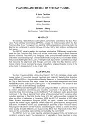
Slurry walls accelerate shaft construction in rock in Los Angeles<br />
M.P. McKenna & K.K. So<br />
<strong>Jacobs</strong> <strong>Associates</strong>, Los Angeles, CA, USA<br />
M.A. Krulc<br />
Traylor Brothers, Los Angeles, CA, USA<br />
E. Itzig-Heine<br />
Ed Heine Construction Services, Leesburg, VA, USA<br />
ABSTRACT: This paper details the challenges associated with the design and construction of a “figureeight”<br />
shaped, or dual cell shaft through soft ground and sedimentary rock for the Northeast Interceptor Sewer<br />
project in Los Angeles. The Humboldt Street Shaft was excavated as two cells, using a combination of both reinforced<br />
and un-reinforced concrete diaphragm walls. The Contractor chose to construct the diaphragm panels to<br />
full depth, using a Hydrofraise rather than sinking them only to the top of rock, thus eliminating the need for<br />
conventional rock support with shotcrete and ribs or dowels. This method of construction is unusual for sedimentary<br />
rock. The two cells varied in diameter and excavated depth, as each served a different purpose. The<br />
21-m-diameter cell was excavated to a depth of 41 m to support tunneling operations and to allow construction<br />
of a junction drop structure and maintenance hole. The 12.5-m-diameter cell was only excavated to a depth of<br />
19 m, allowing the construction of a stub-out connection to a future sewer. Other notable aspects of shaft construction<br />
included the use of rock anchors through the partition wall below the shallow cell and the use of weep<br />
holes through the shaft walls below the top of rock.<br />
1 INTRODUCTION<br />
1.1 Project description<br />
The City of Los Angeles, Department of Public Works,<br />
Bureau of Engineering is presently undertaking two<br />
major construction projects to provide relief and<br />
redundancy for the aging North Outfall Sewer (NOS).<br />
These two projects are the Northeast Interceptor Sewer<br />
(NEIS) and the North Outfall Sewer – East Central<br />
Interceptor Sewer (NOS-ECIS). At the time <strong>this</strong> paper<br />
was written, the joint venture formed by Kenny, Shea,<br />
Traylor, and Frontier-Kemper (KSTFK) had completed<br />
tunneling for NOS-ECIS project. Meanwhile, a separate<br />
joint venture formed by Traylor, Shea, Frontier, and<br />
Kenny (TSFK) is currently mining the NEIS tunnel.<br />
An overall vicinity plan for both projects is shown in<br />
Figure 1. The NEIS project involves the construction<br />
of an 8.5-km-long, 2.4-m-inside-diameter (ID) sewer<br />
pipeline in a 4.0-m-diameter excavated tunnel, three<br />
drop structures, and seven special maintenance holes.<br />
The project must be completed by November 30,<br />
2004 in order to comply with a Cease and Desist Order<br />
(CDO) deadline imposed by the Regional Water Quality<br />
Control Board. When complete, NEIS will convey<br />
flows from existing sewers and the future Eagle Rock<br />
Interceptor Sewer southward to NOS-ECIS.<br />
1.2 Alignment<br />
NEIS will extend from a junction structure with<br />
NOS-ECIS at the intersection of Mission Road and<br />
Jesse Street, northward to the intersection of Division<br />
Street and San Fernando Road, in the Glassell Park<br />
area of Los Angeles, on an alignment roughly parallel<br />
to the east bank of the Los Angeles River. A project<br />
alignment map is provided in Figure 2.<br />
1.3 Site-specific description<br />
This paper focuses on the Humboldt Street work<br />
shaft, one of three work shafts being constructed for<br />
the NEIS project. The Humboldt Shaft is located on<br />
109
Figure 1.<br />
Vicinity map.<br />
Figure 2.<br />
Alignment map.<br />
the site of a former warehouse structure, near the intersection<br />
of Humboldt Street and San Fernando Road<br />
(see Figure 3). The shaft is 41 m deep on one side and<br />
19 m on the other. The design team planned the shaft<br />
to serve three functions, as:<br />
• drive shaft for the middle-reach earth pressure<br />
balance tunnel boring machine (EPBM), tunneling<br />
towards the Richmond Shaft;<br />
• receiving shaft for the upper-reach rock tunnel<br />
boring machine (TBM) tunneling from the Division<br />
Street Shaft;<br />
• work shaft for the stub-out connection tunnel for<br />
future tie-in to NOS.<br />
The design specified that after the tunnels are mined<br />
and the carrier pipe is installed in each reach, a combined<br />
drop-and-junction structure with associated<br />
110
Figure 3.<br />
Site plan.<br />
Figure 4.<br />
Geologic profile.<br />
maintenance holes would be constructed in the deep<br />
shaft.<br />
1.4 Geology<br />
Three major geologic units are present at the Humboldt<br />
Shaft (see Figure 4). The following is a description of<br />
each unit, as described by the Los Angeles Bureau of<br />
Engineering’s Geotechnical Engineering Division<br />
(GED) in the project’s Geotechnical Data Report<br />
(GDR):<br />
• Artificial Fill – Variable in soil type along the<br />
alignment, ranging from clayey silt to angular gravel<br />
and sand.<br />
• Recent Alluvium, (Qal) – Fluvial and alluvial<br />
deposits (channel deposits, point bar deposits, and<br />
flood plain deposits) that have been deposited within<br />
111
the past 10,000 years (Holocene age). It consists<br />
predominantly of cohesionless silty sands, poorly<br />
graded to well-graded sands with gravel, and sands<br />
with silt and gravel.<br />
• Old Alluvium, (Qoal) – These deposits are generally<br />
considered to have formed between 10,000 and<br />
700,000 years ago (upper Pleistocene age). Brown<br />
fine gravel with fine to coarse sand, containing<br />
scattered sand with gravel layers and scattered<br />
organic fragments in a clay/silt matrix.<br />
• Puente Formation, Unit 2 (Tp 2 ) – The lower unit of<br />
the Puente Formation, an interbedded siltstone, claystone,<br />
and sandstone of Miocene age. The Puente<br />
Formation is divided into Tp 1 and the Tp 2 for the<br />
NEIS project. The major difference is that the beds<br />
of the Tp 2 are thicker and notably stronger than the<br />
thinner beds of the overlying Tp 1 .<br />
For the Humboldt Shaft the GBR indicated that up<br />
to 1 m of artificial fill could be expected, underlain by<br />
8 to 9 m of medium dense to very dense recent alluvium,<br />
a thin layer (0 to 1 m thick) of older alluvium,<br />
then Tp 2 to the bottom of the excavation. The groundwater<br />
table lies at a depth of about 9 m.<br />
None of the project borings around the Humboldt<br />
Shaft encountered gas, liquid oil, or tar within the Tp 2<br />
or alluvial soils. However, natural hydrocarbons were<br />
found in several locations along the alignment. Oil and<br />
in <strong>this</strong> part of the Los Angeles Basin originates in the<br />
petroliferous Tp 2 and propagates up along the bedding<br />
planes through seams of sand and silty sand.<br />
Therefore, Cal/OSHA classified <strong>this</strong> shaft as “potentially<br />
gassy” during shaft excavation.<br />
2 CONTRACT REQUIREMENTS<br />
2.1 Slurry walls<br />
The Contract Documents prohibit the Contractor from<br />
dewatering outside the limits of the Humboldt Shaft<br />
excavation. The reason for <strong>this</strong> restriction is to prevent<br />
migration of potential groundwater contamination and<br />
to minimize disruption to the natural groundwater<br />
flow. Therefore, the design team selected reinforced<br />
concrete diaphragm walls (slurry walls) to support<br />
the excavation through the alluvium and to prevent<br />
lowering of the groundwater table outside of the excavation.<br />
The conceptual design of the Humboldt Shaft<br />
shown in the Contract Documents is roughly circular<br />
in shape, with an adjoining shallow rectangular cell to<br />
the south. The conceptual design included 12 wall<br />
panels to approximate a ring and seven to enclose the<br />
shallow shaft for the NOS diversion structure (see<br />
Figure 5), tied together at the surface with a reinforced<br />
concrete cap beam. The design team determined the<br />
Figure 5.<br />
Plan view of conceptual shaft.<br />
112
minimum shaft diameter of a circular shaft at <strong>this</strong> site<br />
to be 21 m in the alluvium and 19 m in rock. These<br />
dimensions were chosen to accommodate the permanent<br />
structures to be constructed within the shaft, as<br />
well as to minimize the amount of rock excavated.<br />
The design of the circular cell assumes the walls act<br />
as a compression ring, carrying the load by thrust in the<br />
panels in the ring’s plane, with no internal bracing<br />
required. The design of the rectangular shaft included<br />
internal steel bracing and additional reinforcing steel in<br />
the wall panels to resist bending stresses. Since slurry<br />
walls are very rigid and generally do not allow significant<br />
ground movement, the lateral earth pressure loading<br />
criteria in the contract documents are a triangular<br />
distribution based on averaging the active and at-rest<br />
earth pressure coefficients (K a and K o respectively).<br />
In addition to the triangular distribution, the design<br />
criteria included an apparent earth pressure envelope<br />
based on the same average K value, which was to be<br />
used only for the internally braced, rectangular cell.<br />
2.2 Rock reinforcement<br />
The geotechnical exploration program indicated that<br />
the Puente Formation is a very weak to moderately<br />
strong rock, with most unconfined compression test<br />
values falling below 5 MPa. The designers felt the<br />
rock strength was adequate to resist the compressive<br />
stresses due to hydrostatic and horizontal rock pressures<br />
in the rock mass around the circular shaft<br />
opening. However, to ensure a ring of intact rock would<br />
carry <strong>this</strong> load in compression, where joint sets and<br />
inclined bedding planes are present, additional rock<br />
support analyses were performed. These analyses<br />
assumed joint orientations and joint strengths developed<br />
from data contained in the GDR and GBR, as<br />
well as shaft geometry and locations of contacts<br />
between rock and soil. The designers calculated an<br />
apparent uniform rock loading, based on the force<br />
required to resist the movement of a wedge of intact<br />
rock sliding along the most prominent joint sets<br />
and/or bedding planes. The pressure diagrams in the<br />
Contract Documents included a uniform rock pressure<br />
of 67 kPa as a minimum requirement for the<br />
Contractor to design the rock support. The Contract<br />
Documents also required the Contractor to install<br />
strip drains with weep holes between the rock surface<br />
and the shotcrete to drain water-bearing joints around<br />
potentially unstable wedges that intersect the shaft<br />
walls. For <strong>this</strong> reason, the rock loading minimum<br />
design criteria did not include hydrostatic pressure for<br />
the design of rock reinforcement.<br />
The conceptual design for rock reinforcement<br />
shown in Figure 6 included two alternatives for ground<br />
support rock:<br />
• W8 ribs at 1.8 m vertical spacing, with 150 mm of<br />
steel-fiber-reinforced shotcrete.<br />
• Rock bolts at about 1.8 m 1.8 m spacing, 8.5 m<br />
long with 150 mm of fiber-reinforced shotcrete.<br />
Figure 6<br />
Section view of conceptual shaft.<br />
113
These alternatives served as a basis for initial<br />
support, with provisions in the contract indicating that<br />
modification to these designs may be required, depending<br />
on conditions observed in the field.<br />
2.3 Geotechnical instrumentation<br />
The contract required the Contractor to install the following<br />
three sets of geotechnical instruments around<br />
and within the Humboldt Shaft:<br />
• three inclinometers (shown as ▲ on Figure 5);<br />
• four piezometers (shown as ■ on Figure 5);<br />
• twelve horizontal multiple-point borehole extensometers.<br />
The inclinometers and piezometers are considered<br />
typical, minimum instrumentation for a shaft of <strong>this</strong><br />
size and depth. The horizontal multiple-point borehole<br />
extensometers are specified for the portion of the<br />
shaft in rock. Their primary purpose is to measure<br />
lateral ground movement and warn of potentially large<br />
block movements. If the maximum lateral movement<br />
of 25 mm were exceeded, additional rock anchors or<br />
steel ribs would be installed to arrest ground movements<br />
and maintain stability of the rock mass.<br />
3 CONTRACTOR’S REVISED DESIGN<br />
3.1 Shaft geometry<br />
The conceptual design consisted of two shafts adjacent<br />
to one another. The small, shallow shaft consisted<br />
of slurry walls with waler and strut supports. It was<br />
intended that the shallow shaft would carry lateral<br />
loads by flexure, which necessitated walers and struts<br />
for support. The large, deep shaft was comprised<br />
of two different support types. In the alluvium and<br />
fill, the deep shaft would carry lateral loads by hoop<br />
compression. In the Puente Formation, rock anchors<br />
and fiber-reinforced shotcrete would carry the loads<br />
directly, or ring beams could be used in hoop<br />
compression.<br />
Using the variety of support systems as described<br />
above would have added time and complexity to the<br />
Contractor’s operations. Therefore, the Contractor<br />
elected to use a “figure-eight” or dual-cell slurry wall<br />
shaft (shown in Figures 7 and 8), similar to the concept<br />
used for the Richmond Shaft. The small cell is<br />
approximately 19 m deep, and the deep cell is approximately<br />
39 m deep. Ed (Itzig) Heine P.E., and Steve<br />
Blumenbaum of Alpha Corporation designed the<br />
dual-cell shaft for <strong>this</strong> joint venture.<br />
3.2 Radial walls<br />
The radial walls were designed by the hoop stress<br />
method and were considered to be unreinforced<br />
compression members. Only the circular band of concrete<br />
inscribed within the limits of the slurry wall panels<br />
was considered effective in compression. The Hydrofraise<br />
(French for hydro-mill) construction method<br />
chosen by the Contractor resulted in average chord<br />
lengths of 2.4 m. The contractor-proposed chord lengths<br />
were much shorter and therefore more efficient in hoop<br />
compression than anticipated in the conceptual design.<br />
Figure 7.<br />
Plan view of contractor’s revised geometry.<br />
114
The short chord lengths afforded the opportunity<br />
omit a cap beam. When long chord lengths are used, a<br />
reinforced concrete cap beam is often used at the top<br />
of the shaft to provide continuity and resistance to<br />
deformation. But with the close approximation of a<br />
circle provided by the shorter panels, a cap beam is<br />
not required.<br />
Steel reinforcement was not needed for the purpose<br />
of resisting lateral loads. However, contingency reinforcing<br />
was installed, in case the panels were not<br />
installed within the specified tolerances. In that event,<br />
the panels could span vertically to remedial ring beams<br />
or walers.<br />
In the Puente Formation, drain holes were provided<br />
in the slurry walls to relieve any groundwater pressures.<br />
This was mostly precautionary, given the relative<br />
impermeability of the formation.<br />
3.3 Center wall<br />
The center wall was designed for different load conditions<br />
depending on depth. Where it is a common wall<br />
between the two cells, the center wall was designed<br />
for compressive horizontal loads coming from the<br />
radial loads in the two cells. It was also designed to<br />
accommodate a 1.5 m differential soil loading between<br />
elevations in each cell. Reinforcement in <strong>this</strong> area was<br />
designed to limit buckling. At elevations below the<br />
bottom of the shallow shaft, the center wall behaves<br />
differently. It is subjected to lateral earth loads as well<br />
as compressive loads coming from the radial wall of<br />
the deep cell. In <strong>this</strong> area, the wall spans vertically,<br />
and reinforcement is used for flexural strength. This<br />
load condition controls the design of the center wall<br />
reinforcing. The wall spans between 9 m long rock<br />
anchors, which are installed on 2 m 4.5 m centers.<br />
Reinforcing cages were only terminated at the top of<br />
rock in the circular portion of the shaft.<br />
At all elevations, the ends of the radial walls were<br />
poured integrally with the end panels of the center<br />
wall, and reinforcement was provided across the center/radial<br />
wall joint. In <strong>this</strong> way, shear transfer across<br />
the joint is ensured.<br />
3.4 Groundwater considerations<br />
In the fill and alluvium, the slurry walls were<br />
designed for the combination of earth and hydrostatic<br />
pressures. In the Puente Formation, the slurry walls<br />
were designed only to support wedges of rock. In<br />
rock, the slurry walls confine the rock mass and the<br />
ground to support the horizontal rock and hydrostatic<br />
pressures present deeper in the rock mass.<br />
Hydrostatic pressures behind the slurry wall and in<br />
water-bearing joints around potentially unstable<br />
wedges intersecting shaft walls are relieved through<br />
the use of weep holes drilled horizontally through the<br />
slurry walls. Weep holes were not drilled through<br />
the walls above the rock to prevent dewatering of the<br />
overlying alluvium. The slurry in the alluvium provides<br />
a water barrier that the designers did not want to<br />
compromise.<br />
3.5 Summary of advantages<br />
There are several advantages to using the dual-cell,<br />
full-depth, slurry wall shaft instead of the conceptual<br />
design. First, the construction methods were simplified<br />
and shortened by using one excavation method.<br />
Second, Hydrofraise construction allowed the<br />
designer to eliminate the cap beam. The shorter chord<br />
lengths also minimized the need for panel reinforcement.<br />
Third, replacing the rectangular small shaft<br />
with a circular one minimized the need for reinforcement<br />
and eliminated the need for walers and struts<br />
in the small shaft. Fourth, no setback was required<br />
to change from slurry wall to rock anchor support.<br />
This not only reduced the footprint of the large shaft,<br />
but it also eliminated the need for a cast-in-place<br />
ring beam at the transition from slurry wall to rock<br />
support.<br />
Figure 8.<br />
Section view of contractor’s shaft.<br />
4 CONSTRUCTION MEANS AND METHODS<br />
4.1 Advantages of hydrofraise method for slurry<br />
wall construction<br />
The TSFK Joint Venture selected Soletanche Inc. as their<br />
slurry wall subcontractor and chose the Hydrofraise<br />
115
excavation method for several reasons, which are<br />
described below:<br />
1. Schedule Advantages – Time restrictions placed on<br />
the Contractor by the CDO required that shaft<br />
construction be expedited.<br />
2. Achieving Tight Tolerances at Depth – The realtime<br />
data supplied to the operator from the fraise<br />
allows precise alignment of each panel which<br />
assures tight vertical joints at depth.<br />
3. Versatility of the Hydrofraise – The Hydrofraise is<br />
able to excavate through all types of materials with<br />
minimal modification to the cutting tools.<br />
4. Minimal Impact on Environment – The Hydrofraise<br />
method imposes minimal impact on the<br />
surrounding environment, which was a necessity<br />
in the densely populated vicinity of the shaft site.<br />
The operating principle of the Hydrofraise is similar<br />
to that of a slurry shield TBM, in which the excavated<br />
opening is supported by a pressurized suspension that<br />
balances the earth and water pressure of the excavation.<br />
In most cases, <strong>this</strong> suspension is a bentonite and<br />
water slurry. The slurry acts not only as a support<br />
fluid, but also as a transport medium. The ground<br />
excavated by the cutting tool is mixed with the support<br />
fluid slurry near the excavation face, where it<br />
can then be pumped to the surface. A separation plant,<br />
usually on the surface, then separates the support fluid<br />
from the ground, and the fluid is again pumped to the<br />
excavation face. Fresh bentonite can be added as<br />
slurry properties dictate.<br />
A typical equipment spread for the Hydrofraise<br />
method is comprised of a modified crane, a fraise cutting<br />
tool, a bentonite slurry mixing and storage facility,<br />
a separation/de-sanding plant, and one or two support<br />
cranes. The specific layout of the Hydrofraise used in<br />
<strong>this</strong> project can be seen in Figure 9.<br />
4.1.1 Schedule advantages<br />
The Hydrofraise can shorten the construction schedule<br />
because of its ability to continuously excavate. The<br />
tool is lowered under its own weight into a pre-built<br />
concrete guide wall, with the cutting wheels turning. It<br />
continues excavating until it reaches the desired depth.<br />
In conventional clamshell excavation, the continual<br />
raising, lowering, and dumping cycles are time consuming.<br />
However, as with any sophisticated piece of<br />
equipment, the Hydrofraise is susceptible to mechanical<br />
and electrical downtime, whereas the clamshell<br />
can be kept running with a minimum of specialized<br />
maintenance, tools, and equipment. However, on the<br />
NEIS project, the Hydrofraise experienced minimum<br />
downtime and was therefore able to keep the project<br />
on schedule. Slurry wall panel construction at the<br />
Humboldt Shaft lasted 49 days, with the crew working<br />
two 10-hour shifts. The approximate area of the<br />
slurry wall panels is 3,381 m 2 , in elevation.<br />
Figure 9.<br />
“The Hydrofraise evolution II” by Soletanche, Inc.<br />
4.1.2 Achieving tight tolerances at depth<br />
One of the major reasons the Contractor chose the<br />
Hydrofraise method was due to its precise excavation<br />
control. The design assumptions of shaft geometry<br />
are dependent upon the construction tolerances that the<br />
equipment can achieve. The cutting tool is equipped<br />
with inclinometers and tilt meters that are linked to a<br />
computer screen in the operator’s cab. The operator is<br />
able to read the information provided by the instrumentation<br />
in real-time and make corrections as<br />
needed. Several features are available to the operator<br />
for steering purposes. First, each of the two rotating<br />
cutting wheels can be run at variable speeds to correct<br />
for left and right misalignment. Second, the entire<br />
cutting head can tilt up to 1.5° in the vertical plane of<br />
excavation to correct for front and back misalignment.<br />
Such precise control over tool guidance enabled the<br />
Hydrofraise to excavate panels on the NEIS project<br />
within a tolerance of 0.3%, which equates to a variance<br />
of only 125 mm from the designed vertical alignment,<br />
over a depth of 42 m.<br />
4.1.3 Versatility of the Hydrofraise<br />
The Hydrofraise cutting tool can quickly and easily<br />
adapt to changes in ground conditions with modifications<br />
to the cutters. Both of the cutting wheels can be<br />
removed and replaced in a single shift, which allows<br />
the Hydrofraise to perform in almost any ground<br />
116
Figure 10.<br />
Photo of broken teeth.<br />
Figure 11.<br />
Excavation in rock.<br />
condition. As an example, at the Richmond Shaft site,<br />
which was the first of three slurry walls constructed<br />
for NEIS, the Hydrofraise was equipped with selfcleaning<br />
cutting paddles to deal with the soft claystone<br />
and mudstone present in the area. However, when harder<br />
sandstone was encountered at the Humboldt site, the<br />
slurry wall Sub-Contractor quickly replaced the paddles<br />
with carbide tipped picks. The carbide picks<br />
performed well; the only problem was chipping of the<br />
carbide tips in the hardest layers of the Tp 2 as shown<br />
in Figure 10. It was the versatility of the Hydrofraise<br />
that enabled the Contractor to further accelerate the<br />
schedule by extending the slurry walls through the<br />
Puente Formation and eliminating rock bolting and<br />
shotcreting from the shaft excavation activities.<br />
4.2 Panel construction sequence<br />
The circular shape of the shaft was approximated<br />
with short chords because the Hydrofraise is limited<br />
to excavating rectangular shaped sections. The chord<br />
length for the Humboldt slurry wall ranged from<br />
1.804 m to 2.448 m. The wall was constructed in 43<br />
“bites,” with each bite being one pass of the cutting<br />
tool. The wall was also constructed in 19 “panels,”<br />
which were either: a primary panel comprised of three<br />
bites, a secondary panel comprised of one bite, or a<br />
follow-up panel of five bites. A secondary panel separated<br />
each primary panel and the follow-up panels<br />
were used to create the joint between the two cells.<br />
Each primary and follow-up panel was excavated<br />
and concreted first, before the secondary panels were<br />
excavated. Tight joints between the primary and secondary<br />
panels were constructed by spacing the primary<br />
panels so that the Hydrofraise cut into the previously<br />
poured concrete of the primary panels, while it was<br />
excavating the secondary panels. The cutting of<br />
the primary panels produced a rough surface for the<br />
concrete of the secondary panels to bond to, thus<br />
producing a strong and relatively watertight joint. The<br />
concrete was poured using dual tremie pipes in<br />
the primary and follow-up panels and a single tremie<br />
pipe in the secondary panels.<br />
4.3 Shaft excavation<br />
Because the shaft was originally classified as “gassy”<br />
by Cal/OSHA, the Contractor chose to drill a test hole<br />
prior to excavation of the shaft for the purpose of<br />
drawing gas samples. It was hoped that the Cal/OSHA<br />
would reclassify the shaft based on favorable results<br />
from these samples, and thus allow the use of conventional<br />
equipment for the shaft excavation. The shaft<br />
was indeed reclassified to “potentially gassy” with<br />
special conditions, based on the gas samples, and the<br />
Contractor was allowed to proceed with conventional<br />
equipment.<br />
The first 5.2 m of the shaft, which consisted mostly<br />
of artificially backfilled sand and alluvial sand and<br />
clay, was excavated from the surface by a Caterpillar<br />
325 excavator. For the next 4 m of excavation, the<br />
CAT 325 excavator was placed in the shaft where it<br />
then loaded two 3.8 m 3 circular muck skips, which<br />
were hoisted on a single line by a 125-ton-capacity<br />
American 9260 crane, as shown in Figure 11. The crane<br />
was previously factory modified for deep tunnel<br />
operations. This 4 m of excavation consisted mostly<br />
of alluvial sand and clay. At an approximate 7.6 m<br />
depth, the soil became sticky and produced a strong<br />
hydrocarbon odor. A chemical analysis of the excavated<br />
material revealed that the soil contained a high<br />
concentration of natural petroleum hydrocarbon,<br />
which is not uncommon in the Los Angeles Basin.<br />
The soil was classified as “Contaminated” and was<br />
removed and dealt with by the Contractor’s environmental<br />
subcontractor.<br />
117
The Tp 2 Formation was encountered at a depth of<br />
9.1 m, at which point the CAT 325 was no longer able<br />
to freely excavate the material with a bucket. Consequently,<br />
a 53 kN hoe-ram was attached to the CAT<br />
325 to break the hard layers of the Tp 2, , while a CAT<br />
312 excavator was put into service to load the broken<br />
material into muck skips. The production rate of each<br />
piece of equipment was quite evenly matched so that<br />
the two excavators could follow each other around the<br />
shaft, one breaking material and one loading material.<br />
The efficiency of the operation led to a production rate<br />
of about 550 m 3 per shift, which equated to approximately<br />
1.2 m (in depth) per shift in the large cell. The<br />
CAT 312 excavator was utilized in the small cell, since<br />
the shaft was not large enough to accommodate the<br />
CAT 325. With aggressive bucket teeth, the CAT 312<br />
was able to excavate nearly all the material down to a<br />
depth of 26 m unassisted. Where it was not able to<br />
dig, a smaller hoe-ram attached to a Case 580 loader<br />
assisted the operation by breaking the harder material.<br />
With these production rates, the shaft was sunk in<br />
39 working days, utilizing two 8-hour shifts per day.<br />
Figure 12.<br />
Drilling weep holes in the slurry wall.<br />
4.4 Rock anchor installation<br />
The rock anchor scheme in the straight center wall of<br />
the shaft consisted of four rows of anchors with five<br />
anchors per row and a vertical and horizontal spacing<br />
of 4 m and 2 m, respectively. The design specified<br />
9 m long, 35-mm-diameter, 1,030 MPa Dywidag<br />
Threadbar anchors, which were to be installed in a<br />
70 mm hole and encapsulated in cementitious grout.<br />
The Contractor chose to use a Gardner-Denver PR<br />
123 rock drill mounted to an ATD 3800 Air Trac drill<br />
carrier (as seen in Figures 12 and 13) for the drilling<br />
in the relatively soft rock of the Tp 2 Formation,<br />
10-m-long, 100 mm diameter holes could be drilled in<br />
a matter of minutes. Shorter holes drilled as weep<br />
holes yielded some water immediately after drilling<br />
and periodically during a relatively dry rainy season<br />
in 2002.<br />
Contract Specifications stated that shaft excavation<br />
was not allowed more than 1 m below a row of anchors<br />
until each bolt was pull tested. In order to gain high<br />
early strength and a quick turnaround on the pull test,<br />
a prepackaged non-shrink rock anchor grout formulated<br />
by Euclid was initially selected for the cementitious<br />
encapsulation. It was to be batched and pumped<br />
by a Hany IC 310 colloidal mixer. A prepackaged product<br />
was selected with the hope that it would reduce<br />
batching times and improve quality assurance of the<br />
grout, since the Contractor could not afford to halt<br />
shaft sinking production in order to reinstall a failed<br />
anchor. However, after a number of unsuccessful<br />
attempts to mix and pump the prepackaged product, it<br />
became apparent that the Euclid material was not compatible<br />
with the Hany equipment at the water-to-cement<br />
Figure 13.<br />
Drilling for rock anchor installation.<br />
ratio the Contractor needed to achieve. It was decided<br />
that a switch would be made to a traditional cementand-water<br />
grout mix. Master Builders MEYCO<br />
Fix Flowcable was added to the mix to reduce water<br />
requirements, increase pumpability, and provide nonshrink<br />
properties. After <strong>this</strong> change was made, the<br />
Hany mixer and pump performed flawlessly. Each<br />
anchor was pull tested approximately 20 hrs after installation,<br />
with all anchors passing, except the last one.<br />
118
execution of the NEIS contract. <strong>Jacobs</strong> <strong>Associates</strong><br />
provided design services for the Department of Public<br />
Works, Bureau of Engineering and prepared the minimum<br />
design criteria used by the Contractor to design<br />
the Humboldt Shaft. Parsons Brinckerhoff Construction<br />
Services/Brown & Root Services (J.V.) and<br />
<strong>Jacobs</strong> <strong>Associates</strong> continue to work with Baron Miya<br />
and Rajni Patel of the Bureau of Engineering as an<br />
integrated team managing the construction of the NEIS<br />
project. Chris Smith and Richard Calvo of the Bureau<br />
of Contracts Administration supervised inspection of<br />
the work and ensured that the slurry walls were constructed<br />
in accordance with the demanding project<br />
specifications.<br />
Figure 14.<br />
Weep holes drilled through the slurry wall.<br />
REFERENCES<br />
The anchor failure is believed to have been caused by<br />
a transient water flow which washed grout out of the<br />
hole. Another anchor was installed immediately and<br />
passed pull testing.<br />
5 CLOSING REMARKS<br />
Excavation of the Humboldt Shaft ended on March<br />
28, 2003. The shaft excavation was never on the<br />
project’s critical path. This can be attributed to the<br />
successfully planned and implemented slurry wall<br />
operation devised by the TSFK joint venture and their<br />
subcontractor, Soletanche Inc. The joint venture kept<br />
the project on schedule through shaft construction,<br />
despite the rigorous demands dictated by the CDO.<br />
McKenna, M. P., Traylor, D. A., Tarralle, B. and Itzig-Heine, E.<br />
2003. Design and Construction of a Deep, Dual-Cell,<br />
Slurry Wall Shaft in Soft Ground, Proceedings of the<br />
Rapid Excavation and Tunneling Conference, 368–382.<br />
City of Los Angeles Department of Public Works, 2001.<br />
Geotechnical Baseline Report: Northeast Interceptor<br />
Sewer (NEIS. City of Los Angeles Department of Public<br />
Works, Bureau of Engineering.<br />
City of Los Angeles Department of Public Works, 2001.<br />
Geotechnical Data Report: Northeast Interceptor Sewer<br />
(NEIS. City of Los Angeles Department of Public Works,<br />
Bureau of Engineering.<br />
ACKNOWLEDGEMENTS<br />
The authors would like to recognize some of the key<br />
firms and individuals responsible for the design and<br />
119