Silicon Pyranometer Smart Sensor (Part # S-LIB-M003)
Silicon Pyranometer Smart Sensor (Part # S-LIB-M003)
Silicon Pyranometer Smart Sensor (Part # S-LIB-M003)

You also want an ePaper? Increase the reach of your titles
YUMPU automatically turns print PDFs into web optimized ePapers that Google loves.
<strong>Silicon</strong> <strong>Pyranometer</strong> <strong>Smart</strong> <strong>Sensor</strong> (<strong>Part</strong> # S-<strong>LIB</strong>-<strong>M003</strong>)<br />
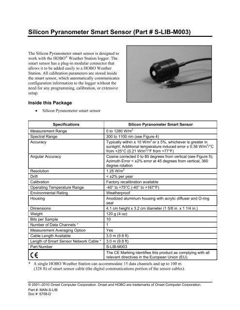
The <strong>Silicon</strong> <strong>Pyranometer</strong> smart sensor is designed to<br />
work with the HOBO ® Weather Station logger. The<br />
smart sensor has a plug-in modular connector that<br />
allows it to be added easily to a HOBO Weather<br />
Station. All calibration parameters are stored inside<br />
the smart sensor, which automatically communicates<br />
configuration information to the logger without the<br />
need for any programming, calibration, or extensive<br />
setup.<br />
Inside this Package<br />
• <strong>Silicon</strong> <strong>Pyranometer</strong> smart sensor<br />
Specifications<br />
<strong>Silicon</strong> <strong>Pyranometer</strong> <strong>Smart</strong> <strong>Sensor</strong><br />
Measurement Range 0 to 1280 W/m 2<br />
Spectral Range 300 to 1100 nm (see Figure 4)<br />
Accuracy<br />
Typically within ± 10 W/m 2 or ± 5%, whichever is greater in<br />
sunlight; Additional temperature induced error ± 0.38 W/m 2 /°C<br />
from +25°C (0.21 W/m 2 /°F from +77°F)<br />
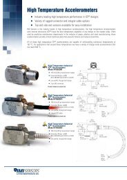
Angular Accuracy Cosine corrected 0 to 80 degrees from vertical (see Figure 5);<br />
Azimuth Error < ±2% error at 45 degrees from vertical, 360<br />
degree rotation<br />
Resolution 1.25 W/m 2<br />
Drift<br />
< ±2% per year<br />
Calibration<br />
Factory recalibration available<br />
Operating Temperature Range<br />
-40° to +75°C (-40° to +167°F)<br />
Environmental Rating<br />
Weatherproof<br />
Housing<br />
Anodized aluminum housing with acrylic diffuser and O-ring<br />
seal<br />
Dimensions<br />
4.1 cm height x 3.2 cm diameter (1 5/8 in. x 1 1/4 in.)<br />
Weight<br />
120 g (4 oz)<br />
Bits per Sample 10<br />
Number of Data Channels * 1<br />
Measurement Averaging Option<br />
Yes<br />
Cable Length Available<br />
3.0 m (9.8 ft)<br />
Length of <strong>Smart</strong> <strong>Sensor</strong> Network Cable * 3.0 m (9.8 ft)<br />
<strong>Part</strong> Number<br />
S-<strong>LIB</strong>-<strong>M003</strong><br />
The CE Marking identifies this product as complying with all<br />
relevant directives in the European Union (EU).<br />
* A single HOBO Weather Station can accommodate 15 data channels and up to 100 m<br />
(328 ft) of smart sensor cable (the digital communications portion of the sensor cables).<br />
© 2001–2010 Onset Computer Corporation. Onset and HOBO are trademarks of Onset Computer Corporation.<br />
<strong>Part</strong> #: MAN-S-<strong>LIB</strong><br />
Doc #: 6708-D
<strong>Silicon</strong> <strong>Pyranometer</strong> <strong>Smart</strong> <strong>Sensor</strong><br />
Mounting<br />
Accessories<br />
• Light <strong>Sensor</strong> Mounting Bracket (<strong>Part</strong> # M-LBB)<br />
• Light <strong>Sensor</strong> Level (<strong>Part</strong> # M-LLA)<br />
Bracket Mounting<br />
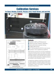
It is recommended that you mount the <strong>Silicon</strong> <strong>Pyranometer</strong> smart sensor with the light sensor bracket on a<br />
pole or tripod (see Figure 1). To mount the sensor using the bracket:<br />
1. Attach the light sensor bracket to a 1¼ inch to 1 5 / 8 inch pole with the provided U-bolts.<br />
Note: The bracket can also be mounted on a flat, vertical surface using four screws.<br />
2. Position the <strong>Silicon</strong> <strong>Pyranometer</strong> sensor on top of the bracket with its cable running through the<br />
slot in the bracket.<br />
3. Using the two screws supplied, attach the sensor to the bracket through the two holes on either<br />
side of the slot.<br />
Note: Do not completely tighten the screws until you level the sensor.<br />
4. Position the bracket so it faces toward the equator, minimizing the chance of shading.<br />
5. Mount the bracket on the mast with the two U-bolt assemblies, mounting it high enough on the<br />
mast to avoid the possibility of shading the sensor.<br />
Note: If you mount the sensor above eye level, use a step ladder or other secure platform when<br />
leveling the sensor so that you can clearly view the Light <strong>Sensor</strong> Level (<strong>Part</strong> # M-LLA).<br />
<strong>Silicon</strong> <strong>Pyranometer</strong><br />
<strong>Smart</strong> <strong>Sensor</strong><br />
Mast<br />
Thumbscrews<br />
<strong>Silicon</strong> <strong>Pyranometer</strong><br />
<strong>Sensor</strong> Cable<br />
Light <strong>Sensor</strong> Bracket<br />
U-bolt Assembly<br />
Figure 1: <strong>Silicon</strong> <strong>Pyranometer</strong> <strong>Sensor</strong> Bracket Mounting<br />
6. Make sure the screws holding the sensor to the mounting bracket are loose.<br />
Page 2 of 6
<strong>Silicon</strong> <strong>Pyranometer</strong> <strong>Smart</strong> <strong>Sensor</strong><br />
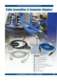
7. Place the Light <strong>Sensor</strong> Level on the <strong>Silicon</strong> <strong>Pyranometer</strong> smart sensor.<br />
8. Adjust the height of the thumbscrews to level the sensor (start with the thumbscrews protruding<br />
about 1/16 inch from the bracket).<br />
9. Once the sensor is near level, tighten the Phillips head screws.<br />
10. Check the level and repeat above steps if necessary (see Figure 2).<br />
11. IMPORTANT: Don’t forget to remove the level when you are done with it.<br />
<strong>Silicon</strong><br />
<strong>Pyranometer</strong><br />
<strong>Sensor</strong><br />
Light <strong>Sensor</strong> Level<br />
(Remove for Operation)<br />
Figure 2: Leveling the <strong>Sensor</strong> on the Light <strong>Sensor</strong> Bracket<br />
Specialized Application Mounting<br />
To mount the <strong>Silicon</strong> <strong>Pyranometer</strong> sensor using a mounting plate of your own design:<br />
1. Drill a 0.56 (9/16) inch hole in the middle of the plate, then drill two #25 holes 1.063 (1-1/16)<br />
inches apart on either side of the center hole. Cut a 0.31 (5/16) inch-wide slot in the mounting<br />
plate. See Figure 3. The plate should be a thickness of 1/8 inch or less.<br />
2. Slide the sensor through the 0.31 (5/16) inch-wide slot.<br />
3. Attach the sensor using two 6-32 x 3/8 inch screws and lock washers (not included).<br />
4. Shim the sensor as necessary to level it.<br />
Figure 3: Recommended Mounting Plate Dimensions<br />
Page 3 of 6
<strong>Silicon</strong> <strong>Pyranometer</strong> <strong>Smart</strong> <strong>Sensor</strong><br />
Mounting Considerations<br />
• Small errors in alignment can produce significant errors. Be certain the sensor is mounted level.<br />
• Mount the sensor where it will not be in a shadow. Any obstruction should be below the plane of<br />
the sensor head. If that is not possible, try to limit obstructions to below 5 degrees, where the<br />
effect will be minimal.<br />
• If possible, avoid placing the sensors in dusty locations. Dust, pollen, and salt residue that collect<br />
on the top of the sensor can significantly degrade accuracy.<br />
• Refer to the HOBO Weather Station User’s Guide for more information about setting up<br />
complete HOBO Weather Stations.<br />
Connecting the <strong>Sensor</strong> to the Logger<br />
To start using the <strong>Silicon</strong> <strong>Pyranometer</strong> smart sensor, stop the HOBO Weather Station logger and insert<br />
the modular jack into an available port. If a port is not available, use a 1-to-2 adaptor, which allows you to<br />
plug two sensors into one port (<strong>Part</strong> # S-ADAPT). The next time you use the HOBO Weather Station, it<br />
will automatically detect the new smart sensor.<br />
The HOBO Weather Station supports a maximum of 15 data channels; this sensor uses one channel.<br />
Launch the logger and verify the sensor is functioning correctly. See the HOBO Weather Station User’s<br />
Guide for more details about connecting smart sensors to the HOBO Weather Station.<br />
Operation<br />
The <strong>Silicon</strong> <strong>Pyranometer</strong> smart sensor supports measurement averaging. When measurement averaging is<br />
enabled, data is sampled more frequently than it is logged. The multiple samples are then averaged<br />
together and the average value is stored as the data for the interval. For example, if the logging interval is<br />
set at 10 minutes and the sampling interval is set at 1 minute, each recorded data point will be the average<br />
of 10 measurements.<br />
Measurement averaging is useful for reducing noise in the data. It is recommended that you use<br />
measurement averaging whenever the <strong>Silicon</strong> <strong>Pyranometer</strong> smart sensor is placed in an area where the<br />
light level can vary quickly with respect to the logging interval (for example, during partly cloudy<br />
conditions). Note that fast sampling intervals (less than 1 minute) may significantly reduce battery life.<br />
See the HOBO Weather Station User’s Guide for more details about sensor operation and battery life.<br />
Page 4 of 6
<strong>Silicon</strong> <strong>Pyranometer</strong> <strong>Smart</strong> <strong>Sensor</strong><br />
Spectral Characteristics<br />
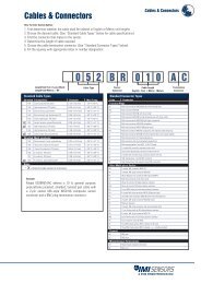
This sensor uses a silicon photodiode to measure solar power per unit area (watts per square meter).<br />
<strong>Silicon</strong> photodiodes are not ideal for use as solar radiation sensors and the photodiode in this <strong>Silicon</strong><br />
<strong>Pyranometer</strong> is no exception (see Figure 4). An ideal pyranometer has equal spectral response from 280 to<br />
2800 nm. However, when calibrated properly and used correctly, the <strong>Silicon</strong> <strong>Pyranometer</strong> smart sensor<br />
should perform well in most situations.<br />
The sensor is calibrated for use in sunlight (an Eppley Precision Spectral <strong>Pyranometer</strong> is used as reference<br />
standard). Accordingly, if the sensor is used under natural sunlight, the measurement errors will be small.<br />
Note that significant errors may result from using the sensor under artificial light, within plant canopies,<br />
in greenhouses, or any other conditions where the spectral content differs from sunlight.<br />
Sun's Relative Intensity and the Typical Relative Response of<br />
the <strong>Silicon</strong> <strong>Pyranometer</strong> versus Wavelength<br />
1.0<br />
1.0<br />
Sun's Relative Intensity<br />
0.9<br />
0.8<br />
0.7<br />
0.6<br />
0.5<br />
0.4<br />
0.3<br />
0.2<br />
0.1<br />
<strong>Silicon</strong> <strong>Pyranometer</strong><br />
Sunlight<br />
0.9<br />
0.8<br />
0.7<br />
0.6<br />
0.5<br />
0.4<br />
0.3<br />
0.2<br />
0.1<br />
Photodetector Relative Response<br />
0.0<br />
250 750 1250 1750 2250<br />
Wavelength (nm)<br />
0.0<br />
Figure 4: S-<strong>LIB</strong>-<strong>M003</strong> <strong>Silicon</strong> <strong>Pyranometer</strong> Response Curve<br />
Page 5 of 6
<strong>Silicon</strong> <strong>Pyranometer</strong> <strong>Smart</strong> <strong>Sensor</strong><br />
Cosine Correction<br />
The <strong>Silicon</strong> <strong>Pyranometer</strong> smart sensor housing is designed to give an accurate cosine response. Figure 5<br />
shows a plot of relative intensity versus angle of incidence for a typical sensor and for the theoretical ideal<br />
response. Deviation from ideal response is less than 5% from 0 to 70 degrees and less than 10% from 70<br />
to 80 degrees.<br />
Note that as the angle approaches 90 degrees, the ideal cosine response approaches zero. As a result,<br />
small errors in measured intensity will result in very large percentage errors compared to the ideal<br />
response from 80 to 90 degrees.<br />
Typical Cosine Response of <strong>Silicon</strong> <strong>Pyranometer</strong><br />
120<br />
Percent Relative Response<br />
100<br />
80<br />
60<br />
40<br />
Ideal Response<br />
<strong>Silicon</strong> <strong>Pyranometer</strong><br />
20<br />
0<br />
0 10 20 30 40 50 60 70 80 90 100<br />
Angle from Vertical (Degrees)<br />
Figure 5: S-<strong>LIB</strong>-<strong>M003</strong> Typical Cosine Response Curve<br />
Maintenance<br />
Dust on the sensor will degrade sensor accuracy. Periodically inspect the sensor and if necessary, gently<br />
clean the diffuser with a damp sponge. Do not open the sensor as there are no user serviceable parts<br />
inside.<br />
Warning: DO NOT use alcohol, organic solvents, abrasives, or strong detergents to clean the diffuser<br />
element on the <strong>Silicon</strong> <strong>Pyranometer</strong> smart sensor. The acrylic material used in the sensor can be crazed by<br />
exposure to alcohol or organic solvents. Clean the sensor only with water and/or a mild detergent such as<br />
dishwashing soap if necessary. It is recommended that you use vinegar to remove hard water deposits<br />
from the diffuser element. Under no circumstances should the sensor be immersed in any liquid.<br />
Verifying <strong>Sensor</strong> Accuracy<br />
It is recommended that you test the <strong>Silicon</strong> <strong>Pyranometer</strong> smart sensor annually for accuracy. If the sensor<br />
is not providing accurate data, it may be damaged or out of calibration. If you are unsure of accuracy,<br />
send the smart sensor back to Onset for testing and possible re-calibration. Only Onset can complete<br />
calibration. Contact Onset or your dealer for a Return Merchandise Authorization (RMA) number before<br />
sending the sensor.<br />
Page 6 of 6