Signal converter for electromagnetic flowmeters
Signal converter for electromagnetic flowmeters
Signal converter for electromagnetic flowmeters

You also want an ePaper? Increase the reach of your titles
YUMPU automatically turns print PDFs into web optimized ePapers that Google loves.
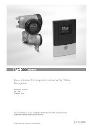
IFC 300 Supplementary instructions<br />
<strong>Signal</strong> <strong>converter</strong> <strong>for</strong> <strong>electromagnetic</strong> <strong>flowmeters</strong><br />
Description of Modbus interface<br />
Electronic Revision: ER 3.3.xx (SW.REV. 3.3x)<br />
Modbus version 1.2.x<br />
© KROHNE 07/2010 - 4000410703 - AD Modbus IFC 300 R03 en
CONTENTS<br />
IFC 300<br />
1 Important in<strong>for</strong>mation 3<br />
2 Technical data 4<br />
2.1 General technical data .....................................................................................................4<br />
2.2 Technical data of the Modbus interface (acc. to EIA standards) ..................................... 4<br />
3 Connection in bus systems 5<br />
4 Local configuration 6<br />
5 Electrical connection 7<br />
6 Modbus protocol 8<br />
6.1 General in<strong>for</strong>mation concerning the protocol ................................................................. 8<br />
6.2 RTU frame <strong>for</strong>mat............................................................................................................. 8<br />
6.3 Addressing........................................................................................................................ 9<br />
6.4 Overview of supported functions...................................................................................... 9<br />
6.5 Device identification on the Modbus interface............................................................... 10<br />
6.6 Coil registers .................................................................................................................. 10<br />
6.6.1 Converter controls ................................................................................................................ 10<br />
6.6.2 Counter controls ................................................................................................................... 11<br />
6.6.3 Start calibration functions .................................................................................................... 11<br />
6.7 Input registers ................................................................................................................ 12<br />
6.8 Holding registers............................................................................................................ 14<br />
6.8.1 Counter parameters ............................................................................................................. 14<br />
6.8.2 Process input filter parameters ........................................................................................... 15<br />
6.8.3 Modbus parameters.............................................................................................................. 17<br />
6.9 Diagnostics ..................................................................................................................... 17<br />
6.10 Calibration procedures................................................................................................. 18<br />
6.10.1 Zero Flow Calibration.......................................................................................................... 18<br />
6.10.2 Coil Temperature Calibration ............................................................................................. 19<br />
6.10.3 Conductivity Calibration...................................................................................................... 20<br />
7 Notes 21<br />
2 www.krohne.com 07/2010 - 4000410703 - AD Modbus IFC 300 R03 en
IFC 300<br />
IMPORTANT INFORMATION 1<br />
The flow <strong>converter</strong> with the RS485 interface card fitted, is able to communicate with an external<br />
device (PC or other suitable computer system) using the Modbus protocol. This option allows<br />
data exchange between PC or computer and single or multiple devices.<br />
The bus configuration consists of one external device as a master and one or more <strong>converter</strong>s as<br />
slaves. For bus operation the device address (menu C5.8.1), baudrate (menu C5.8.2) and settings<br />
(menu C5.8.3, C5.8.4, C5.8.5 & C5.8.6) must be set in the <strong>converter</strong>.<br />
All devices connected to the bus, must have different unique addresses but the same baud rate<br />
and settings.<br />
07/2010 - 4000410703 - AD Modbus IFC 300 R03 en<br />
www.krohne.com<br />
3
2 TECHNICAL DATA<br />
IFC 300<br />
2.1 General technical data<br />
Interface<br />
RS485, galvanically isolated<br />
Baud rate 1200, 2400, 4800, 9600, 19200, 38400, 57600 or 115200<br />
Protocol<br />
Maximum participants on bus<br />
Coding<br />
Modbus RTU (available as a separate document on request)<br />
32 per line, master included (may be extended by repeaters)<br />
NRZ bit coding<br />
Address range Modbus: 1...247<br />
Transmission procedure<br />
Bus access<br />
Cable<br />
Distances<br />
Half duplex, asynchronous<br />
Master / slave<br />
Screened twisted pair<br />
Maximum 1.2 km / 3937 ft without repeater (dependant on<br />
baud rate and cable specifications)<br />
2.2 Technical data of the Modbus interface (acc. to EIA standards)<br />
Kind of signal transmission<br />
Maximum number of<br />
transmitter/receivers<br />
Voltage range on <strong>converter</strong> input<br />
Maximum voltage on <strong>converter</strong> output<br />
Minimum voltage on driver output, max.<br />
load<br />
Maximum input current (off state)<br />
Receiver input voltage<br />
Sensitivity of the receiver<br />
Receiver input resistance<br />
Short circuit current<br />
Termination / polarization resistors<br />
(if activated by the jumpers X5/X6)<br />
Differential, 2-wire topology<br />
32<br />
-7...+12 V<br />
5V<br />
U diff >1.5V<br />
-20...+20 μA<br />
-7...+12 V<br />
-200...+200 mV<br />
>12kΩ<br />
< 250 mA<br />
120 Ω / 560 Ω<br />
4<br />
www.krohne.com<br />
07/2010 - 4000410703 - AD Modbus IFC 300 R03 en
IFC 300<br />
CONNECTION IN BUS SYSTEMS 3<br />
For proper operation of Modbus in half duplex mode in single or multi-drop communication, it is<br />
recommended that a termination resistor is applied to both ends of the data line. The simplest<br />
<strong>for</strong>m of termination is line-to-line resistor across the differential input.<br />
In RTU mode the Modus protocol requires quiet periods on the communications bus <strong>for</strong><br />
synchronisation. It is there<strong>for</strong>e important that the Modbus is not allowed to "float", i.e.<br />
unreferenced to 0 V, as this could lead to spurious signals due to noise pick-up. It is there<strong>for</strong>e<br />
necessary to employ biasing resistors at one point on the bus network, normally the "end".<br />
The Modbus <strong>converter</strong> has two conditions. Default is without termination and polarization. To get<br />
the active termination and polarization the settings of jumper X5 and X6 on Modbus board must<br />
be changed then. For detailed in<strong>for</strong>mation see chapter "Electrical Connection".<br />
07/2010 - 4000410703 - AD Modbus IFC 300 R03 en<br />
www.krohne.com<br />
5
4 LOCAL CONFIGURATION<br />
IFC 300<br />
Converter Fct.<br />
No.<br />
Display<br />
Description and settings<br />
C5.8.1 Slave Address Selects the Modbus address of the device.<br />
Range: 1..247 (default = 1)<br />
C5.8.2 Baud Rate Selects the baud rate of the device.<br />
Options:<br />
1200 / 2400 / 3600 / 4800 / 9600 / 19200 (default) / 38400 / 57600 / 115200<br />
C5.8.3 Parity Selects the parity.<br />
Options:<br />
Even (default) / Odd / No<br />
C5.8.4 Data Format Selects the data <strong>for</strong>mat.<br />
Options:<br />
Big Endian (default) / Little Endian<br />
C5.8.5 Transmission Delay Selects the delay between receiving the last byte of a request and<br />
sending the first byte of the response.<br />
Range: 0..40ms (default = 0ms)<br />
C5.8.6 Stop Bits Selects the number of stop bits.<br />
Options:<br />
1 (default) / 2<br />
C5.8.7 In<strong>for</strong>mation Displays in<strong>for</strong>mation about the device.<br />
6<br />
www.krohne.com<br />
07/2010 - 4000410703 - AD Modbus IFC 300 R03 en
IFC 300<br />
ELECTRICAL CONNECTION 5<br />
Terminals A and B of the <strong>converter</strong> are dependant on the options selected at order. Refer to the<br />
standard handbook of the <strong>converter</strong> <strong>for</strong> connection details.<br />
Modbus connections<br />
Terminals<br />
Description<br />
D- <strong>Signal</strong> A (D 0)<br />
D <strong>Signal</strong> B (D 1)<br />
C- Common 0 V<br />
C<br />
Not connected<br />
Jumper settings on the Modbus printed circuit board<br />
Jumper position<br />
Description<br />
X5 X6<br />
1-2 1-2 With termination and polarization<br />
2-3 2-3 Without termination and polarization<br />
07/2010 - 4000410703 - AD Modbus IFC 300 R03 en<br />
www.krohne.com<br />
7
6 MODBUS PROTOCOL<br />
IFC 300<br />
6.1 General in<strong>for</strong>mation concerning the protocol<br />
Using RTU (Remote Terminal Unit) <strong>for</strong>mat, data is transmitted as 8 bit binary characters. There<br />
are no special characters to determine the start and end of a message frame.<br />
Synchronization is achieved by a minimum silent period of at least 3.5 character times be<strong>for</strong>e the<br />
start of each frame transmission and a maximum silent period of 1.5 character times between<br />
characters in the same frame.<br />
6.2 RTU frame <strong>for</strong>mat<br />
The <strong>for</strong>mat of the query and response frames vary slightly depending upon the command<br />
function. The basic <strong>for</strong>m is outlined below.<br />
Command function Frame <strong>for</strong>mat Description<br />
Silent period 3.5 x T All transmissions must be preceded by a minimum silent<br />
period of 3.5 x T, where T is the transmission time of a<br />
single character. This can be calculated from the baud<br />
rate, e.g. at 19.2 kb no parity with 1 stop bit (10 bits),<br />
T=520µs.<br />
Slave address 8bits This is a single byte slave address which is transmitted<br />
first and must be in the range of 1...247. Address 0 is<br />
reserved <strong>for</strong> a broadcast address which all slaves should<br />
recognize, and there<strong>for</strong>e requires no response.<br />
Function code 8bits This is an eight bit code in the range of 1...255 although<br />
only 126 functions exist as the codes 129...255 represent<br />
an error condition. An error condition occurs when the<br />
addressed slave does not accept the command, in which<br />
case it responds with the function code + 128, i.e. with its<br />
MSB set to 1.<br />
Register start address or<br />
byte count when required<br />
8 bit byte count<br />
16 bit address<br />
Register start address: <strong>for</strong> a query command that requires<br />
data to be returned, this field will contain the 16 bit start<br />
address of the register (or data) to be returned.<br />
Note that the <strong>converter</strong> uses protocol addresses.<br />
There<strong>for</strong>e the register address listed is the actual number<br />
required in the Modbus command.<br />
E.g: to access input register 30006, the register start<br />
address is 30006dec = 7536hex.<br />
Number of points or data<br />
bytes when required<br />
n×8bits<br />
Byte count: In general this is only present in frames that<br />
are transferring data, and has a value equal to the number<br />
of bytes contained in the data field. The data field is limited<br />
to a maximum of 250 bytes.<br />
Number of points: <strong>for</strong> a query command that requires data<br />
to be returned, this field will contain the number of<br />
registers to be returned regardless of their bit size.<br />
Data bytes: contains the data requested. The <strong>converter</strong> can<br />
use big endian <strong>for</strong>mat (MSB first) or little endian<br />
<strong>for</strong>mat (LSB first).<br />
CRC 16 bits This field contains a 16 bit CRC which is calculated on all<br />
the data bits of the message bytes.<br />
8<br />
www.krohne.com<br />
07/2010 - 4000410703 - AD Modbus IFC 300 R03 en
IFC 300<br />
MODBUS PROTOCOL 6<br />
6.3 Addressing<br />
In the following tables the Modbus protocol addresses / data addresses are listed.<br />
Some systems cannot use addresses above 9999. For these systems there is the possibility to<br />
use the listed addresses but<br />
• <strong>for</strong> Input Registers omit the leading 3 of 3xxxx;<br />
• <strong>for</strong> Holding Registers omit the leading 4 of 4xxxx;<br />
• <strong>for</strong> Input Registers replace the leading 20 of 20xxx by 9xxx.<br />
Sometimes register numbers are asked <strong>for</strong>. The register numbers can be calculated by adding a<br />
1 to the protocol address and using a prefix according to the block:<br />
• prefix 1 <strong>for</strong> coils<br />
• prefix 3 <strong>for</strong> Input Registers<br />
• prefix 4 <strong>for</strong> Holding Registers<br />
6.4 Overview of supported functions<br />
The following table shows Modbus functions supported by RS485 interface.<br />
Function code Name Access to<br />
hex dec<br />
01 01 Read Single Coil Status of calibration functions, counter<br />
status (start/stop)<br />
03 03 Read Holding Register Converter configuration parameter<br />
04 04 Read Input Register Measurement values, status values and<br />
calibration results<br />
05 05 Write Single Coil Cold start, warm start, error reset, start<br />
calibration function, start/stop counter<br />
08 08 Diagnostics -<br />
10 16 Write Multiple Register Converter configuration parameter<br />
07/2010 - 4000410703 - AD Modbus IFC 300 R03 en<br />
www.krohne.com<br />
9
6 MODBUS PROTOCOL<br />
IFC 300<br />
6.5 Device identification on the Modbus interface<br />
The device identification is according to the category "Regular" according to the Modbus<br />
Application Protocol Specification V1.1a. Function code 43 / 14 (0x2B / 0x0E).<br />
Modbus object Id Object name / Description Type Content<br />
0x00 VendorName 16 byte ASCII String KROHNE<br />
0x01 ProductCode 10 byte ASCII String CG number; order code <strong>for</strong> the<br />
<strong>converter</strong> assembly<br />
0x02 MajorMinorRevision 7 byte ASCII String V1.2.xx<br />
0x03 Vendor URL 32 byte ASCII String www.krohne.com<br />
0x04 ProductName 16 byte ASCII String IFC300<br />
0x05 ModelName 16 byte ASCII String Modbus<br />
0x06 UserApplicationName 16 byte ASCII String User tag, displayed on the<br />
header of the local screen<br />
6.6 Coil registers<br />
These function codes are used <strong>for</strong> access:<br />
• 0x01 = read input coil<br />
• 0x05 = write single coil<br />
6.6.1 Converter controls<br />
Coil address<br />
Function<br />
1000 Write 1 generates a cold start, write 0 is ignored<br />
1001 Write 1 generates a warm start, write 0 is ignored<br />
1002 Write 1 generates an error reset, write 0 is ignored<br />
10<br />
www.krohne.com<br />
07/2010 - 4000410703 - AD Modbus IFC 300 R03 en
IFC 300<br />
MODBUS PROTOCOL 6<br />
6.6.2 Counter controls<br />
Modbus protocol<br />
address<br />
Description Settings Converter Fct. No.<br />
3000 Start / Stop Write 1 start counter C3.1.8 / C3.1.9<br />
Counter 1<br />
Write 0 stop counter<br />
Read 1 counter is running<br />
Read 0 counter is stopped<br />
3001 Start / Stop Write 1 start counter C3.2.8 / C3.2.9<br />
Counter 2<br />
Write 0 stop counter<br />
Read 1 counter is running<br />
Read 0 counter is stopped<br />
3002 Start / Stop Write 1 start counter C3.3.8 / C3.3.9<br />
Counter 3 1<br />
Write 0 stop counter<br />
Read 1 counter is running<br />
Read 0 counter is stopped<br />
3003 Reset Counter 1 Write 1 reset counter C3.1.6<br />
Write 0 -<br />
Read 0 -<br />
3004 Reset Counter 2 Write 1 reset counter C3.2.6<br />
Write 0 -<br />
Read 0 -<br />
3005 Reset Counter 3 1 Write 1 reset counter C3.3.6<br />
Write 0 -<br />
Read 0 -<br />
1 Only available in <strong>converter</strong>s with IO2. A write attempt to a non-existing counter will cause an error response.<br />
6.6.3 Start calibration functions<br />
Modbus protocol<br />
address<br />
Description Settings Converter Fct. No.<br />
2000 Zero Calibration Write 1 start function C1.1.1<br />
Write 0 -<br />
Read 0 -<br />
2001 Coil Temperature Write 1 start function C1.1.8<br />
Calibration<br />
Write 0 -<br />
Read 0 -<br />
2002 Electrode Factor Write 1 start function C1.1.11<br />
Calibration<br />
Write 0 -<br />
Read 0 -<br />
07/2010 - 4000410703 - AD Modbus IFC 300 R03 en<br />
www.krohne.com<br />
11
6 MODBUS PROTOCOL<br />
IFC 300<br />
6.7 Input registers<br />
Measurement and status values are read only and can be accessed as Modbus "Input Registers".<br />
Also the result of a calibration procedure is accessed by an input register at Modbus Protocol<br />
Address 20000 or 9000. The type are one or more float values.<br />
Function code is 04 (0x04).<br />
1: not available <strong>for</strong> senor option PF (partly filled)<br />
2: not available <strong>for</strong> senor option CAP (capacitive)<br />
3: only available <strong>for</strong> senor option PF (partly filled)<br />
Modbus protocol<br />
address<br />
Description and settings Type Number of registers<br />
1st<br />
2nd<br />
30000 0 flow speed [m/s] float 2<br />
30002 2 volume flow [m 3 /s] float 2<br />
30004 4 mass flow [kg/s] (1) float 2<br />
30004 4 level [%] (3) float 2<br />
30006 6 coil temperature [K] float 2<br />
30008 8 conductivity [S/m]<br />
This value may not be measured.<br />
Depending on register (4)2003.<br />
0 = off (not measured)<br />
1 = conductivity [S/m]<br />
2 = cond. + empty pipe (S) [S/m]<br />
3 = cond. + empty pipe (F) [S/m]<br />
4 = cond. + empty pipe (I) [S/m]<br />
float 2<br />
For the sensor option PF and CAP this<br />
value is only used <strong>for</strong> empty pipe<br />
detection.<br />
30010 10 diagnosis value<br />
This value may not be measured.<br />
float 2<br />
Depending on register (4)2011.<br />
25 = off (not measured)<br />
31 = electrode noise [m/s]<br />
28 = flow profile [no unit] (1, 2)<br />
21 = linearity [no unit] (1, 2)<br />
8 = terminal 2 DC [Volt] (2)<br />
9 = terminal 3 DC [Volt] (2)<br />
30012 12 Display Channel 1<br />
Represents the value on the first line of<br />
float 2<br />
the first measurement screen in SI units<br />
30014 14 Display Channel 2<br />
Represents the value on the first line of<br />
float 2<br />
the second measurement screen in SI<br />
units<br />
30016 16 Operating time [s] float 2<br />
30018 18 Not used, returns zero float 2<br />
30020 20 Counter 1 [m 3 ] or [kg] double float 4<br />
30024 24 Counter 2 [m 3 ] or [kg] double float 4<br />
12<br />
www.krohne.com<br />
07/2010 - 4000410703 - AD Modbus IFC 300 R03 en
IFC 300<br />
MODBUS PROTOCOL 6<br />
Modbus protocol<br />
address<br />
Description and settings Type Number of registers<br />
1st<br />
2nd<br />
30028 28 Counter 3 [m 3 ] or [kg]<br />
double float 4<br />
Note: this counter is only available <strong>for</strong><br />
<strong>converter</strong> with IO 2!<br />
30032 32 long status sensor byte [4] 2<br />
30034 34 long status device byte [4] 2<br />
30036 36 long status sensor option PF (3) byte [4] 2<br />
Input register (3)0018 is not used up to now. This is included to fill the gap between the float and<br />
double float values and allows to read the full range of registers.<br />
07/2010 - 4000410703 - AD Modbus IFC 300 R03 en<br />
www.krohne.com<br />
13
6 MODBUS PROTOCOL<br />
IFC 300<br />
6.8 Holding registers<br />
Some parameters of the device can be accessed as Modbus holding registers.<br />
Function code 03 (0x03) <strong>for</strong> "Read" operations and function code 16 (0x10) <strong>for</strong> "Write" operations.<br />
The holding registers are grouped into the following different sections.<br />
6.8.1 Counter parameters<br />
INFORMATION!<br />
Counter 3 parameters are only available <strong>for</strong> <strong>converter</strong> with IO 2.<br />
1: not available <strong>for</strong> senor option PF (partly filled)<br />
2: not available <strong>for</strong> senor option CAP (capacitive)<br />
3: only available <strong>for</strong> senor option PF (partly filled)<br />
Modbus protocol<br />
address<br />
Description and settings<br />
Converter Fct.<br />
No.<br />
Type<br />
Number of<br />
registers<br />
1st<br />
2nd<br />
40000 0 counter 1 function<br />
1=sum counter<br />
C3.1.1 byte 1<br />
2=+counter<br />
3 = - counter<br />
0=off<br />
40001 1 measurement Cnt1 (1)<br />
21 = volume flow<br />
C3.1.2 word 1<br />
22 = mass flow<br />
40001 1 measurement Cnt1 (3)<br />
27 = volume flow<br />
C3.1.2 word 1<br />
40002 2 counter 2 function<br />
1=sum counter<br />
C3.2.1 byte 1<br />
2=+counter<br />
3 = - counter<br />
0=off<br />
40003 3 measurement Cnt2 (1)<br />
21 = volume flow<br />
C3.2.2 word 1<br />
22 = mass flow<br />
40003 3 measurement Cnt2 (3)<br />
C3.2.2 word 1<br />
27 = volume flow<br />
40004 4 counter 3 function<br />
1=sum counter<br />
C3.3.1 byte 1<br />
2=+counter<br />
3 = - counter<br />
0=off<br />
40005 5 measurement Cnt3 (1)<br />
21 = volume flow<br />
C3.3.2 word 1<br />
22 = mass flow<br />
40005 5 measurement Cnt3 (3)<br />
27 = volume flow<br />
C3.3.2 word 1<br />
41000 1000 low flow cutoff value Cnt1 [m 3 /s] or [kg/s] C3.1.3 float 2<br />
41002 1002 time constant Cnt1 [s] C3.1.4 float 2<br />
14<br />
www.krohne.com<br />
07/2010 - 4000410703 - AD Modbus IFC 300 R03 en
IFC 300<br />
MODBUS PROTOCOL 6<br />
Modbus protocol<br />
address<br />
Description and settings<br />
Converter Fct.<br />
No.<br />
Type<br />
Number of<br />
registers<br />
1st 2nd<br />
41004 1004 set counter Cnt1 or read Cnt1 [m 3 ] or [kg] C3.1.7 float 2<br />
41006 1006 low flow cutoff value Cnt2 [m 3 /s] or [kg/s] C3.2.3 float 2<br />
41008 1008 time constant Cnt2 [s] C3.2.4 float 2<br />
41010 1010 set counter Cnt2 or read Cnt2 [m 3 ] or [kg] C3.2.7 float 2<br />
41012 1012 low flow cutoff value Cnt3 [m 3 /s] or [kg/s] C3.3.3 float 2<br />
41014 1014 time constant Cnt3 [s] C3.3.4 float 2<br />
41016 1016 set counter Cnt3 or read Cnt3 [m 3 ] or [kg] C3.3.7 float 2<br />
41018 1018 preset counter 1 [m 3 ] or [kg] C3.1.5 float 2<br />
41020 1020 preset counter 2 [m 3 ] or [kg] C3.2.5 float 2<br />
41022 1022 preset counter 3 [m 3 ] or [kg] C3.3.5 float 2<br />
6.8.2 Process input filter parameters<br />
1: not available <strong>for</strong> senor option PF (partly filled)<br />
2: not available <strong>for</strong> senor option CAP (capacitive)<br />
3: only available <strong>for</strong> senor option PF (partly filled)<br />
4: only available <strong>for</strong> senor option CAP (capacitive)<br />
Modbus protocol<br />
address<br />
Description and settings<br />
Converter Fct.<br />
No.<br />
Type<br />
Number of<br />
registers<br />
1st<br />
2nd<br />
42000 2000 flow direction<br />
0=normal direction<br />
1 = reverse direction<br />
42001 2001 pulse filter<br />
0=off<br />
1=on<br />
2 = automatic<br />
42002 noise filter<br />
0=off<br />
1=on<br />
42003 2003 empty pipe (1, 2)<br />
0=off<br />
1 = conductivity<br />
2 = cond. + empty pipe (S)<br />
3 = cond. + empty pipe (F)<br />
4 = cond. + empty pipe (I)<br />
42003 2003 empty pipe (3, 4)<br />
0=off<br />
1 = conductivity<br />
2 = empty pipe (S)<br />
3 = empty pipe (F)<br />
4 = empty pipe (I)<br />
42004 2004 full pipe (1, 2)<br />
0=off<br />
1=on<br />
C1.2.2 byte 1<br />
C1.2.4 byte 1<br />
C1.2.7 byte 1<br />
C1.3.1 byte 1<br />
C1.3.1 byte 1<br />
C1.3.4 byte 1<br />
07/2010 - 4000410703 - AD Modbus IFC 300 R03 en<br />
www.krohne.com<br />
15
6 MODBUS PROTOCOL<br />
IFC 300<br />
Modbus protocol<br />
address<br />
Description and settings<br />
Converter Fct.<br />
No.<br />
Type<br />
Number of<br />
registers<br />
1st<br />
2nd<br />
42005 2005 linearity (1, 2)<br />
0=off<br />
C1.3.6 byte 1<br />
1=on<br />
42006 2006 gain<br />
0=off<br />
C1.3.8 byte 1<br />
1=on<br />
42007 2007 coil current<br />
0=off<br />
C1.3.9 byte 1<br />
1=on<br />
42008 2008 flow profile (1, 2)<br />
0=off<br />
C1.3.10 byte 1<br />
1=on<br />
42009 2009 electrode noise<br />
0=off<br />
C1.3.13 byte 1<br />
1=on<br />
42010 2010 settling of field<br />
0=off<br />
C1.3.16 byte 1<br />
1=on<br />
42011 2011 diagnosis value<br />
25 = off<br />
C1.3.17 byte 1<br />
31 = electrode noise<br />
28 = flow profile (1, 2)<br />
21 = linearity (1, 2)<br />
8=terminal2DC (2)<br />
9=terminal3DC (2)<br />
43000 3000 limitation low [m/s] C1.2.1 float 2<br />
43002 3002 limitation high [m/s] C1.2.1 float 2<br />
43004 3004 time constant [s] C1.2.3 float 2<br />
43006 3006 pulse width [s] C1.2.5 float 2<br />
43008 3008 pulse limitation [m/s] C1.2.6 float 2<br />
43010 3010 noise level [m/s] C1.2.8 float 2<br />
43012 3012 noise suppression C1.2.9 float 2<br />
43014 3014 low flow cutoff value [m/s] C1.2.10 float 2<br />
43016 3016 limit empty pipe [S/m] C1.3.3 float 2<br />
43018 3018 limit full pipe [S/m] (1, 2) C1.3.5 float 2<br />
43020 3020 limit flow profile (1, 2) C1.3.11 float 2<br />
43022 3022 limit electrode noise [m/s] C1.3.14 float 2<br />
43024 3024 Zero point [m/s] C1.1.1 float 2<br />
43026 3026 Coil Resistance Rsp, 20 [Ω] C1.1.7 float 2<br />
43028 3028 Coil Temperature Calpoint [K] C1.1.8 float 2<br />
43030 3030 Coil Resistance Calpoint [Ω] C1.1.8 float 2<br />
43032 3032 Electrode Factor EF [m] C1.1.11 float 2<br />
43034 3034 Conductivity Calpoint [S/m] C1.1.11 float 2<br />
43036 3036 Conductivity Calpoint [S/m] C1.1.11 float 2<br />
16<br />
www.krohne.com<br />
07/2010 - 4000410703 - AD Modbus IFC 300 R03 en
IFC 300<br />
MODBUS PROTOCOL 6<br />
6.8.3 Modbus parameters<br />
Modbus protocol<br />
address<br />
6.9 Diagnostics<br />
Description and settings<br />
The Modbus interface supports the diagnostic function defined by the "Modbus Application<br />
Protocol Specification".<br />
Function code is 08 (0x08).<br />
Converter Fct.<br />
No.<br />
Type<br />
50000 baud rate<br />
1200 / 2400 / 3600 / 4800 / 9600 / 19200<br />
C5.8.2 ulong 2<br />
(default) / 38400 / 57600 / 115200<br />
50002 slave address C5.8.1 byte 1<br />
50003 parity<br />
0 = even parity (default)<br />
C5.8.3 byte 1<br />
1 = odd parity<br />
3=no parity<br />
50004 data <strong>for</strong>mat<br />
1=Big Endian<br />
2 = Little Endian<br />
C5.8.4 byte 1<br />
Number of<br />
registers<br />
Sub function code<br />
Name<br />
hex dec<br />
00 00 Return Query Data<br />
01 01 Restart Communication Option<br />
04 04 Force Listen Only Mode<br />
0A 10 Clear Counters<br />
0B 11 Return Bus Message Count<br />
0C 12 Return Bus Communication Error Count<br />
0D 13 Return Bus Exception Count<br />
0E 14 Return Slave Message Count<br />
0F 15 Return Slave No Response Count<br />
10 16 Return Slave NAK Count (counter not used)<br />
11 17 Return Slave Busy Count (counter not used)<br />
12 18 Return Bus Character Overrun Count<br />
07/2010 - 4000410703 - AD Modbus IFC 300 R03 en<br />
www.krohne.com<br />
17
6 MODBUS PROTOCOL<br />
IFC 300<br />
6.10 Calibration procedures<br />
6.10.1 Zero Flow Calibration<br />
1 User reduces the actual flow through the meter to<br />
zero<br />
2 Start zero calibration:<br />
Set single coil 2000 to 1 (Modbus Fct. 0x05)<br />
3 Check status of calibration<br />
Read single coil 2000 (Modbus Fct. 0x01)<br />
3a [2000 == 1: calibration running]<br />
3b [2000 == 0: calibration complete]<br />
4 Read Calibration Value<br />
Read Input Register 20000 type float<br />
(Modbus Fct. 0x04)<br />
5 User checks the calibration value:<br />
-0.01...+0.01: good results<br />
-0.1...+0.1: acceptable result <strong>for</strong> difficult<br />
application<br />
5a Not ok<br />
5b ok<br />
6 User tries to improve the calibration situation<br />
6a Improvement done<br />
6b Improvement not possible<br />
-Break-<br />
7 Write the calibration value<br />
Write Holding Register 43024 type float<br />
(Modbus Fct. 0x10)<br />
8 Activate new values<br />
Set single coil 1001 to 1 (Modbus Fct. 0x05)<br />
8a This results in a warm start of the device.<br />
Will take maximum 5s.<br />
18<br />
www.krohne.com<br />
07/2010 - 4000410703 - AD Modbus IFC 300 R03 en
IFC 300<br />
MODBUS PROTOCOL 6<br />
6.10.2 Coil Temperature Calibration<br />
1 Read actual Rsp,20<br />
Read Holding Register 43026 type float<br />
(Modbus Fct. 0x03)<br />
2 User checks the value with the calibration value<br />
on the type plate of the device<br />
2a Rsp,20 not correct<br />
2b<br />
Write correct Rsp,20<br />
Write Holding Register 43026 type float<br />
(Modbus Fct. 0x10)<br />
2c Rsp,20 correct or corrected<br />
3 User enters the actual coil temperature in K<br />
This is the target <strong>for</strong> the calibration<br />
4 Write actual coil temperature<br />
Write Holding Register 43028 type float<br />
(Modbus Fct. 0x10)<br />
5 Start coil temperature calibration:<br />
Set single coil 2001 to 1 (Modbus Fct. 0x05)<br />
6 Check status of calibration:<br />
Read single coil 2001 (Modbus Fct. 0x01)<br />
6a [2001 == 1: calibration running]<br />
6b [2001 == 0: calibration complete]<br />
7 Read Calibration Value<br />
Read Input Register 20000 type foat<br />
(Modbus Fct. 0x04)<br />
8 Write the calibration value<br />
Write Holding Register 43030 type foat<br />
(Modbus Fct. 0x10)<br />
9 Activate new values<br />
Set single coil 1001 to 1 (Modbus Fct. 0x05)<br />
9a This results in a warm start of the device.<br />
Will take maximum 5s.<br />
07/2010 - 4000410703 - AD Modbus IFC 300 R03 en<br />
www.krohne.com<br />
19
6 MODBUS PROTOCOL<br />
IFC 300<br />
6.10.3 Conductivity Calibration<br />
1 User enters the actual conductivity in S/m<br />
This is the target <strong>for</strong> the calibration<br />
2 Write actual conductivity<br />
Write Holding Register 43034 type float<br />
(Modbus Fct. 0x10)<br />
3 Write actual conductivity<br />
Write Holding Register 43036 type float<br />
(Modbus Fct. 0x10)<br />
3a The target value has to be written to both<br />
registers!<br />
4 Start conductivity calibration:<br />
Set single coil 2002 to 1 (Modbus Fct. 0x05)<br />
5 Check status of calibration:<br />
Read single coil 2002 (Modbus Fct. 0x01)<br />
5a [2002 == 1: calibration running]<br />
5b [2002 == 0: calibration complete]<br />
6 Read Calibration Value<br />
Read Input Register 20000 type float<br />
(Modbus Fct. 0x04)<br />
7 Write the calibration value<br />
Write Holding Register 43032 type float<br />
(Modbus Fct. 0x10)<br />
8 Activate new values<br />
Set single coil 1001 to 1 (Modbus Fct. 0x05)<br />
8a This results in a warm start of the device.<br />
Will take maximum 5s.<br />
20<br />
www.krohne.com<br />
07/2010 - 4000410703 - AD Modbus IFC 300 R03 en
IFC 300<br />
NOTES 7<br />
07/2010 - 4000410703 - AD Modbus IFC 300 R03 en<br />
www.krohne.com<br />
21
7 NOTES<br />
IFC 300<br />
22<br />
www.krohne.com<br />
07/2010 - 4000410703 - AD Modbus IFC 300 R03 en
IFC 300<br />
NOTES 7<br />
07/2010 - 4000410703 - AD Modbus IFC 300 R03 en<br />
www.krohne.com<br />
23
KROHNE product overview<br />
© KROHNE 07/2010 - 4000410703 - AD Modbus IFC 300 R03 en - Subject to change without notice.<br />
• Electromagnetic <strong>flowmeters</strong><br />
• Variable area <strong>flowmeters</strong><br />
• Ultrasonic <strong>flowmeters</strong><br />
• Mass <strong>flowmeters</strong><br />
• Vortex <strong>flowmeters</strong><br />
• Flow controllers<br />
• Level meters<br />
• Temperature meters<br />
• Pressure meters<br />
• Analysis products<br />
• Measuring systems <strong>for</strong> the oil and gas industry<br />
• Measuring systems <strong>for</strong> sea-going tankers<br />
Head Office KROHNE Messtechnik GmbH<br />
Ludwig-Krohne-Str. 5<br />
D-47058 Duisburg (Germany)<br />
Tel.:+49 (0)203 301 0<br />
Fax:+49 (0)203 301 10389<br />
info@krohne.de<br />
The current list of all KROHNE contacts and addresses can be found at:<br />
www.krohne.com