Download brochure 257 KB (pdf) - Weishaupt
Download brochure 257 KB (pdf) - Weishaupt
Download brochure 257 KB (pdf) - Weishaupt

You also want an ePaper? Increase the reach of your titles
YUMPU automatically turns print PDFs into web optimized ePapers that Google loves.
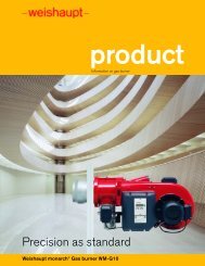
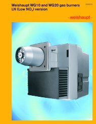
<strong>Weishaupt</strong> gas burners G1 to G7<br />
Version LN (Low NO x )<br />
1/2003 CA
Description<br />
The <strong>Weishaupt</strong> G1 to G7 version LN<br />
gas burners fulfil the requirements for<br />
operational safety, simple installation<br />
and reliability. They are energy<br />
efficient and environmentally friendly.<br />
The burners are in compliance with<br />
most applicable European and North<br />
American standards.<br />
The burners have numerous excellent<br />
features such as:<br />
■ Compliance with the most stringent<br />
requirements and NO x emission limits.<br />
■ Broad operating range; suitable for<br />
many applications<br />
■ Automatic sequence of operations<br />
■ Safe flame monitoring<br />
■ Stable fan reference line - good<br />
combustion characteristic<br />
■ Quiet operation<br />
■ Burner housing can be hinged open<br />
■ As with the standard burners - easy to<br />
install, set and service thanks to easily<br />
accessible components<br />
■ Automatic air shut off on burner shut<br />
down<br />
Construction<br />
All the components are brought together<br />
in a single unit. The burner motor’s axis is<br />
at right angles to the direction of the air<br />
flow and drives the fan wheel’s axle. All the<br />
fuel and air regulating components are<br />
clearly arranged and easily accessible.<br />
The burners can be hinged open to the<br />
left or right which facilitates easy access<br />
to the combustion head, diffuser and<br />
ignition electrodes.<br />
Fuels<br />
The gas burners have been tested for<br />
operation with natural gas.<br />
Application<br />
The burners can be used with heat<br />
exchangers such as hot water boilers,<br />
steam boilers and air heaters, and for<br />
various process applications. As the<br />
burners are capable of overcoming high<br />
combustion chamber resistances, they<br />
are used primarily on high efficiency<br />
boilers.<br />
Regulation<br />
Depending on fuel, burner size and<br />
requirements, the regulation of air and<br />
fuel is by:<br />
■ Sliding two stage Z<br />
■ Sliding two stage ZM<br />
■ Modulation (utilizing an appropriate<br />
controller, the sliding two stage ZM<br />
burner can modulate with a<br />
servomotor runtime of 42 s).<br />
Sliding two stage Z burners operate with<br />
a faster capacity regulation. They are<br />
equipped with a servomotor with a<br />
runtime of 8 s. The air damper and the<br />
gas butterfly valve are operated in<br />
compound connected to each other by a<br />
regulating cam. The proportional amount<br />
of gas and air prevents start-up or<br />
change-over impact in the combustion<br />
chamber or main gas.<br />
Sliding two stage ZM and modulating<br />
burners operate with a slower capacity<br />
regulation. The air damper and the gas<br />
butterfly valve are operated in compound<br />
by means of a regulating cam. The<br />
runtime from low fire to high fire<br />
depending on the servomotors can be a<br />
maximum of 20 or 42 s.<br />
For sliding two stage control, low and<br />
high fire are adjusted within the<br />
regulation range. The burner’s firing rate<br />
slides between the two load points,<br />
depending on the heat demand.<br />
Therefore there are no sudden large<br />
increases or decreases in the amount of<br />
fuel being burned.<br />
Modulating burners operate at any point<br />
within the regulation range, depending<br />
on the heat demand.<br />
Burner overview – rating in MBH<br />
G1/LN<br />
185–1,025<br />
Reduced capacity at start-up with gas<br />
operation<br />
The burners start at ignition position. In<br />
this way only a small amount of gas flows<br />
into the combustion chamber. After a<br />
short delay the gas for the main flame is<br />
released.<br />
Controlled shut downs from low fire.<br />
The controlled shut down of the burner<br />
always takes place from the low fire<br />
position, this prevents impact on the<br />
main gas line.<br />
Flame safeguard<br />
The burner flame safeguard sequences<br />
and controls the operation of the burner<br />
automatically. The flame safeguard can<br />
be located in either the remote control<br />
panel or mounted directly on the burner<br />
(ISG burner version).<br />
Gas trains<br />
As standard <strong>Weishaupt</strong> gas burners are<br />
always supplied with two (2) safety shut<br />
off valves in the gas train.<br />
Installation sites<br />
In standard version (materials, construction,<br />
protection), the burners are<br />
suitable only for use indoors at<br />
temperatures between 5°F and 100°F<br />
(-15°C and +40°C).<br />
G3/LN<br />
G5/LN<br />
270–1,900<br />
680–3,070<br />
G7/LN<br />
850–5,300<br />
2<br />
1,000 3,000 5,000
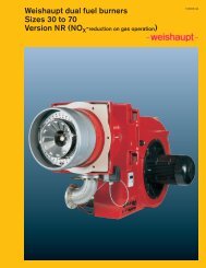
Exemplary emission figures with G1 to G7<br />
LN (LowNO x ) version gas burners<br />
ppm<br />
50<br />
40*<br />
30<br />
20<br />
10<br />
0<br />
NO x<br />
LN Version<br />
CO<br />
Notes and remarks<br />
The emission figures were achieved<br />
with test gas burners.<br />
Excellent emission figures are<br />
achievable depending on the<br />
dimensions of the combustion<br />
chamber, volume loading and design of<br />
the combustion system (3 pass or<br />
reverse flame).<br />
When stating information relating to<br />
guaranteed values, certain conditions<br />
for measurement and evaluation must<br />
be taken into account, such as<br />
combustion chamber loading, test<br />
tolerances, temperature, pressure,<br />
humidity.<br />
* According to German TA-<br />
Luft regulation<br />
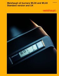
Typical flame formation for LN (LowNO x ) version gas burners<br />
3
G3/1-E gas burner, version Z-LN<br />
LN version gas burner: the mixing assembly is very good accessible.<br />
4
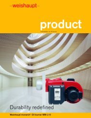
Burner rating dependent on combustion<br />
chamber resistance<br />
Depending on the altitude of the installation, reduction in<br />
capacity of approx. 1% for every 328 ft (100 m) above sea<br />
level should be taken into account.<br />
All ratings given are based on fuel with low calorific value,<br />
an air temperature of 68°F (20°C) and an installation<br />
altitude of 1,640 ft (500 m)<br />
“WC Burner model G1/1-E, version LN<br />
Combustion head type G1/3a-105 x 36<br />
Rating MBH 185 – 1,025<br />
2.0<br />
1.5<br />
1.0<br />
0.5<br />
0<br />
-0.5<br />
-1.0<br />
MBH 0 200 400 600 800 1,000<br />
“WC Burner model G3/1-E, version LN<br />
Combustion head type G3/3a-120 x 41<br />
Rating MBH 270 – 1,880<br />
3<br />
2<br />
1<br />
0<br />
-1.0<br />
MBH 0 200 400 600 800 1,000 1,200 1,400 1,600 1,800<br />
“WC Burner model G5/1-D, version ZM-LN<br />
Combustion head type G5/3a-162 x 50<br />
Rating MBH 680 – 3,075<br />
3.0<br />
2.0<br />
1.0<br />
0<br />
-1.0<br />
MBH 0 600 1,200 1,800 2,400 3,000<br />
“WC Burner model G7/1-D, version LN<br />
Combustion head type G7/3a-190 x 60<br />
Rating MBH 850 – 5,290<br />
5.0<br />
4.0<br />
3.0<br />
2.0<br />
1.0<br />
0.0<br />
-1.0<br />
-2.0<br />
MBH 0 1,000 2,000 3,000 4,000 5,000<br />
combust. head<br />
“Open”<br />
“Closed”<br />
“WC Burner model G1/1-E, version ZMA-LN<br />
Combustion head type G1/3a-105 x 36<br />
Rating MBH 100 – 1,025<br />
2.0<br />
1.5<br />
1.0<br />
0.5<br />
0<br />
-0.5<br />
-1.0<br />
MBH 0 200 400 600 800 1,000<br />
“WC Burner type G3/1-E, version ZMA-LN<br />
Combustion head type G3/3a-120 x 41<br />
Rating MBH 170 – 1,880<br />
3<br />
2<br />
1<br />
0<br />
-1.0<br />
MBH 0 200 400 600 800 1,000 1,200 1,400 1,600 1,800<br />
“WC Burner model G5/1-D, version ZMA-LN<br />
Combustion head type G5/3a-162 x 50<br />
Rating MBH 445 – 3,075<br />
3.0<br />
2.0<br />
1.0<br />
0<br />
-1.0<br />
MBH 0 600 1,200 1,800 2,400 3,000<br />
“WC Burner type G7/1-D, version ZMA-LN<br />
Combustion head type G7/3a-190 x 60<br />
Rating MBH 500 – 5,290<br />
5.0<br />
4.0<br />
3.0<br />
2.0<br />
1.0<br />
0.0<br />
-1.0<br />
-2.0<br />
MBH 0 1,000 2,000 3,000 4,000 5,000<br />
5
Special equipment<br />
Sizes 1 to 3<br />
No. Description G1-LN G3-LN<br />
Order No.<br />
Order No.<br />
1 Downward firing burner version standard standard<br />
2 Air intake flange for connection of an air duct 210 000 67 210 000 67<br />
3 Combustion head extension by 4” (100 mm) 250 002 83 250 002 86<br />
by 8” (200 mm) 250 002 84 250 002 87<br />
by 12” (300 mm) 250 002 85 250 002 88<br />
4 Integral switchgear (ISG) G, version ZE 250 000 02 250 000 06<br />
G, version ZD 250 000 04 250 000 08<br />
G, version ZME 250 001 31 250 001 29<br />
G, version ZMD 250 001 32 250 001 30<br />
5 Flame sensor (UV cell) instead of ionization electrode 250 002 95 250 002 95<br />
6 Potentiometer on servomotor ZM 220 Ohm 110 002 86 110 002 86<br />
ZM 1000 Ohm 110 003 03 110 003 03<br />
7 Solenoid valve for air pressure switch test<br />
for continuous run fan 250 000 54 250 000 54<br />
Sizes 5 to 7<br />
No. Description G5-LN G7-LN<br />
Order No.<br />
Order No.<br />
1 Downward firing burner version standard standard<br />
2 Air intake flange for connection of an air duct 110 001 05 110 001 06<br />
3 Combustion head extension by 4” (100 mm) 150 012 53 150 012 78<br />
by 8” (200 mm) 150 012 54 150 012 79<br />
by 12” (300 mm) 150 012 55 150 012 80<br />
4 Integral switchgear (ISG) G, version ZE – –<br />
G, version ZD 150 006 54 150 006 56<br />
G, version ZME – –<br />
G, version ZMD 150 010 22 150 010 93<br />
5 Flame sensor (UV cell) instead of ionization electrode 150 012 63 150 012 63<br />
6 Potentiometer on servomotor ZM 220 Ohm 110 002 86 110 002 86<br />
ZM 1000 Ohm 110 003 03 110 003 03<br />
7 Solenoid valve for air pressure switch test<br />
for continuous run fan 150 010 07 150 010 07<br />
6
Burner specifications and<br />
Standard scope of supply<br />
Description<br />
for burner<br />
G1 . . LN G3 . . LN G5 . . LN G7 . . LN<br />
Burner motor 1 120V, 60 Hz Model EC90/50-2 EC90/90-2 – –<br />
Nominal capacity HP 0.8 2 – –<br />
Full load current at 120V A 7.5 18 – –<br />
Speed 1/min 3450 3450 – –<br />
Capacitor µF 16 16+16 – –<br />
Burner motor 3 460V Model D90/50-2 D90/50-2 D90/90-2 D112/110-2/1<br />
Nominal capacity HP 1.14 1.14 2.1 4.8<br />
Full load current at 460V A 2.3 2.3 3.4 6.3<br />
Speed 1/min 3400 3400 3360 3500<br />
Fan wheel galvanized galvanized galvanized galvanized<br />
Ignition unit Model W-ZG02/2 W-ZG02/2 W-ZG02/1 W-ZG02/1<br />
Burner flame safeguard for<br />
– single and sliding two stage Z,<br />
sliding two stage ZM and<br />
modulating burners G and GL Model LFL 1.335 LFL 1.335 LFL 1.335 LFL 1.335<br />
Servomotor<br />
– single and sliding two stage Z (run time 8 s) Model -w- 1055/80 -w- 1055/80 -w- 1055/80 -w- 1055/80<br />
– sliding two stage ZM (run time 20 s) Model SQM 10.15561 SQM 10.15561 SQM 10.15561 SQM 10.15561<br />
– modulating burners (run time 42 s) Model SQM 10.16561 SQM 10.16561 SQM 10.16561 SQM 10.16561<br />
Weight<br />
Gas burner (without gas train) lbs/ kg (approx.) 86/ 39 95/ 43 121/ 55 167/ 76<br />
Standard burner motor version: Isolation Class F, type of protection IP54. Other motor voltages and frequencies are available upon request<br />
Burner model G1 to 3 G5 to 7<br />
version LN<br />
version LN<br />
Burner housing with integrated sound<br />
dampened air inlet<br />
●<br />
Burner housing, air control housing<br />
Hinged flange, housing with sight glass,<br />
<strong>Weishaupt</strong> burner motor, pressure side air regulation,<br />
fan wheel, air pressure switch, servomotor, gas/air compound<br />
regulation with regulating cam(s), ignition unit, terminal rails,<br />
flange gasket, fixing screws ● ●<br />
Mixing head for NO x reduction ● ●<br />
Limit switch on hinged flange ● ●<br />
Burner flame safeguard with flame sensor (ionization electrode)<br />
loose for installing in the control panel or mounted on burner (ISG) ● ●<br />
Double main gas valves<br />
Gas butterfly valve ● ●<br />
Gas pressure switch ● ●<br />
●<br />
9<br />
Legend<br />
1 Isolating ball valve<br />
2 Gas pressure regulator<br />
3 Low gas pressure switch<br />
4 Double main gas valves<br />
5 High gas pressure switch<br />
8 Integrated gas butterfly valve<br />
9 Gas burner<br />
P<br />
P<br />
2 3 4 1 5<br />
8<br />
7
Dimensions<br />
<strong>Weishaupt</strong> Corporation<br />
6280 Danville Road<br />
Mississauga, ON L5T 2H7<br />
Ph: (905) 564 0946, Fax: (905)564 0949<br />
www.weishaupt-corp.com<br />
Print No. 83012916, August 2001<br />
Printed in Germany. All rights reserved.<br />
Sizes 1 and 3 Sizes 5 and 7<br />
Flange connection<br />
Flange connection<br />
Drilling<br />
dimensions of the<br />
burner plate<br />
Drilling<br />
dimensions of the<br />
burner plate<br />
Size<br />
Dimensions in inches and (mm)<br />
l1 l2 l3 l4 l5 l6 l7 l8 l9 ➀ l9 ➁ l10 ➀ l10 ➁ b1 ➀ b1 ➁ b2 b3<br />
1 27.0 6.6 5.7 6.6 1.4 3.5 0.3<br />
–<br />
12.3 13.5 4.3 4.7 21.4 25.7 19.7 10.8<br />
(685) (168) (144) (168) (35) (88) (8)<br />
(312) (342) (110) (120) (543) (653) (501) (275)<br />
3 31.7 7.4 5.8 7.4 1.1 3.9 0.3<br />
–<br />
15.4 15.0 4.3 4.7 22.4 26.8 20.8 11.6<br />
(805) (188) (147) (188) (28) (98) (8)<br />
(392) (382) (110) (120) (570) (680) (529) (295)<br />
5 34.2 7.9 7.8 8.2 1.7 4.3 0.3 9.4 17.8 16.6 4.3 4.7 10.8 15.4 10.8 12.0<br />
(868) (200) (197) (208) (42) (108) (8) (238) (451) (421) (110) (120) (275) (390) (275) (305)<br />
7 38.0 8.9 10.9 9.0 2.0 4.6 0.3 9.9 20.2 19.1 4.3 4.7 12.0 16.3 12.8 13.0<br />
(965) (225) (277) (228) (52) (118) (8) (251) (514) (484) (110) (120) (305) (415) (326) (330)<br />
b4 b5 h1 h2 h3 h4 h5 d1 d2 d3 d4 d5 d6 d7 r1 r2<br />
1 9.8<br />
–<br />
15.3 11.4 5.9 6.9 5.1 7.7 5.1<br />
DN25<br />
5.0<br />
M8<br />
6.3-6.7 5.3 21.7 23.2<br />
(248)<br />
(388) (290) (150) (175) (130) (195) (129)<br />
(127) (160-170) (135) (550) (590)<br />
3 11.0<br />
–<br />
16.9 12.8 6.7 6.9 5.5 8.7 6.1<br />
DN40<br />
6.3<br />
M10<br />
7.3 6.5 25.6 26.4<br />
(280)<br />
(430) (325) (170) (175) (140) (220) (154)<br />
(160) (186) (165) (650) (670)<br />
5 12.3 7.9 19.4 14.7 8.7 7.7 6.4 10.2 7.7<br />
DN50<br />
7.9<br />
M10<br />
9.3 8.3 26.8 28.5<br />
(312) (200) (494) (373) (220) (195) (162) (260) (195)<br />
(200) (235) (210) (680) (725)<br />
7 14.0 9.0 22.0 16.3 9.6 7.7 7.2 13.0 9.3<br />
DN65<br />
9.8<br />
M12<br />
11.7 10.6 28.3 31.5<br />
(355) (229) (560) (415) (245) (195) (182) (330) (235)<br />
(250) (298) (270) (720) (800)<br />
➀<br />
➁<br />
Sliding two stage Z burner<br />
Sliding two stage ZM burner