CR1000 Manual - Campbell Scientific
CR1000 Manual - Campbell Scientific
CR1000 Manual - Campbell Scientific

You also want an ePaper? Increase the reach of your titles
YUMPU automatically turns print PDFs into web optimized ePapers that Google loves.
2.0<br />
2.1<br />
3.0<br />
10<br />
3.0.1<br />
3.2.1 3<br />
3.3<br />
3.3.1 ‐‐ 8 10<br />
4.0<br />
4.0.1 ‐‐ 10<br />
4.2 ‐‐ 8 10<br />
4.4<br />
3.5.0<br />
3.5.0a<br />
5.0<br />
5.1 ‐‐ 8 10<br />
5.2.1 9<br />
6.0<br />
6.0.1<br />
6.2<br />
6.3<br />
6.4<br />
6.4.1<br />
7.0<br />
7.0.1<br />
7.0<br />
7.0.1<br />
7.2<br />
LOW<br />
7.3<br />
HIGH<br />
7.4<br />
SWITCH‐CLOSURE<br />
7.5<br />
EDGE‐TIMING<br />
7.6<br />
OUTPUT<br />
7.7<br />
OUTPUT<br />
7.8<br />
INPUT<br />
7.9<br />
INPUT<br />
7.10<br />
7.12<br />
8.1<br />
9.0<br />
9.1<br />
9.2<br />
9.3<br />
9.5<br />
10.0<br />
10.1<br />
10.2<br />
10.3<br />
10.4<br />
11.0<br />
11.1<br />
11.2 ‐‐ 8 10<br />
11.3<br />
11.4<br />
12.0<br />
12.1<br />
12.2<br />
13.0<br />
13.1<br />
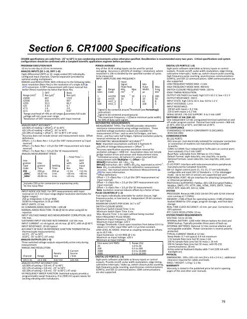
Section 6. <strong>CR1000</strong> Specifications<br />
1.1<br />
<strong>CR1000</strong> specifications are valid from ─25° to 50°C in non‐condensing environments unless otherwise specified. Recalibration is recommended every two years. Critical specifications and system<br />
configurations should be confirmed with a <strong>Campbell</strong> <strong>Scientific</strong> applications engineer before purchase.<br />
PROGRAM EXECUTION RATE<br />
ms to one day at 10 ms increments<br />
ANALOG INPUTS (SE 1–16, DIFF 1–8)<br />
Eight differential (DIFF) or 16 single‐ended (SE) individually<br />
configured input channels. Channel expansion provided by<br />
optional analog multiplexers.<br />
3.1.0<br />
RANGES and RESOLUTION: With reference to the following table,<br />
basic resolution (Basic Res) is the resolution of a single A/D (p.<br />
447) conversion. A DIFF measurement with input reversal has<br />
better (finer) resolution by twice than Basic Res.<br />
3.1.1 ‐‐ 8 10<br />
DIFF<br />
Basic<br />
Range (mV) 1<br />
±5000<br />
±2500<br />
±250<br />
±25<br />
±7.5<br />
±2.5<br />
Res (μV) 2<br />
667<br />
333<br />
33.3<br />
3.33<br />
1.0<br />
0.33<br />
Res (μV)<br />
1333<br />
667<br />
66.7<br />
6.7<br />
2.0<br />
0.67<br />
1 Range overhead of ≈9% on all ranges guarantees full‐scale<br />
voltage will not cause over‐range.<br />
2 Resolution of DIFF measurements with input reversal.<br />
3.2 ‐‐ 8 10<br />
ANALOG INPUT ACCURACY 3 :<br />
±(0.06% of reading + offset 3 ), 0° to 40°C<br />
±(0.12% of reading + offset 3 ), ‐25° to 50°C<br />
±(0.18% of reading + offset 3 ), ‐55° to 85°C (‐XT only)<br />
Accuracy does not include sensor and measurement noise. Offset<br />
definitions:<br />
Offset = 1.5 x Basic Res + 1.0 µV (for DIFF measurement w/ input<br />
reversal)<br />
Offset = 3 x Basic Res + 2.0 µV (for DIFF measurement w/o input<br />
reversal)<br />
Offset = 3 x Basic Res + 3.0 µV (for SE measurement)<br />
ANALOG MEASUREMENT SPEED:<br />
‐‐‐Total Time 4 ‐‐‐<br />
Integration<br />
Inte‐<br />
Type gration<br />
Code Time<br />
250 250 µs<br />
_60Hz 5 16.67 ms<br />
_50Hz 5 20.00 ms<br />
Settling<br />
Time<br />
450 µs<br />
3 ms<br />
3 ms<br />
SE<br />
with<br />
no<br />
Rev<br />
≈1 ms<br />
≈20 ms<br />
≈25 ms<br />
4 Includes 250 μs for conversion to engineering units.<br />
5 AC line noise filter<br />
DIFF<br />
with<br />
Input<br />
Rev<br />
≈12 ms<br />
≈40 ms<br />
≈50 ms<br />
3.4<br />
INPUT‐NOISE VOLTAGE: For DIFF measurements with input<br />
reversal on ±2.5 mV input range (digital resolution dominates for<br />
higher ranges):<br />
250 μs Integration: 0.34 μV RMS<br />
50/60 Hz Integration: 0.19 μV RMS<br />
INPUT LIMITS: ±5 Vdc<br />
DC COMMON‐MODE REJECTION: >100 dB<br />
NORMAL‐MODE REJECTION: 70 dB @ 60 Hz when using 60 Hz<br />
rejection<br />
INPUT VOLTAGE RANGE W/O MEASUREMENT CORRUPTION: ±8.6<br />
Vdc max.<br />
SUSTAINED‐INPUT VOLTAGE W/O DAMAGE: ±16 Vdc max.<br />
INPUT CURRENT: ±1 nA typical, ±6 nA max. @ 50°C; ±90 nA @ 85°C<br />
INPUT RESISTANCE: 20 GΩ typical<br />
ACCURACY OF BUILT‐IN REFERENCE JUNCTION THERMISTOR (for<br />
thermocouple measurements):<br />
±0.3°C, ‐25° to 50°C<br />
±0.8°C, ‐55° to 85°C (‐XT only)<br />
ANALOG OUTPUTS (VX 1–3)<br />
Three switched voltage outputs sequentially active only during<br />
measurement.<br />
4.0.2<br />
RANGES AND RESOLUTION:<br />
4.1 ‐‐ 8 10<br />
Channel<br />
Range<br />
Resolution<br />
Current<br />
Source<br />
/ Sink<br />
(VX 1–3) ±2.5 Vdc 0.67 mV ±25 mA<br />
ANALOG OUTPUT ACCURACY (VX):<br />
±(0.06% of setting + 0.8 mV, 0° to 40°C<br />
±(0.12% of setting + 0.8 mV, ‐25° to 50°C<br />
±(0.18% of setting + 0.8 mV, ‐55° to 85°C (‐XT only)<br />
VX FREQUENCY SWEEP FUNCTION: Switched outputs provide a<br />
programmable swept frequency, 0 to 2500 mV square waves for<br />
exciting vibrating wire transducers.<br />
PERIOD AVERAGE<br />
Any of the 16 SE analog inputs can be used for period<br />
averaging. Accuracy is ±(0.01% of reading + resolution), where<br />
resolution is 136 ns divided by the specified number of cycles<br />
to be measured.<br />
INPUT AMPLITUDE AND FREQUENCY:<br />
3.5.1 ‐‐ 8 10<br />
Input<br />
Signal<br />
Min<br />
Voltage<br />
Gain<br />
1<br />
10<br />
33<br />
100<br />
Range<br />
Code<br />
mV250<br />
mV25<br />
mV7_5<br />
mV2_5<br />
Peak‐Peak<br />
Min<br />
mV 6<br />
500<br />
10<br />
5<br />
2<br />
Max<br />
V 7<br />
10<br />
2<br />
2<br />
2<br />
Pulse<br />
Width<br />
µs<br />
2.5<br />
10<br />
62<br />
100<br />
Max<br />
Freq<br />
kHz 8<br />
200<br />
50<br />
8<br />
5<br />
6 Signal to be centered around Threshold (see PeriodAvg()<br />
instruction).<br />
7 Signal to be centered around ground.<br />
8 The maximum frequency = 1/(twice minimum pulse width)<br />
for 50% of duty cycle signals.<br />
RATIOMETRIC MEASUREMENTS<br />
MEASUREMENT TYPES: The <strong>CR1000</strong> provides ratiometric<br />
resistance measurements using voltage excitation. Three<br />
switched voltage excitation outputs are available for<br />
measurement of four‐ and six‐wire full bridges, and two‐,<br />
three‐, and four‐wire half bridges. Optional excitation polarity<br />
reversal minimizes dc errors.<br />
5.2 ‐‐ 8 10<br />
RATIOMETRIC MEASUREMENT ACCURACY 9,11<br />
Note Important assumptions outlined in footnote 9:<br />
±(0.04% of Voltage Measurement + Offset 12 )<br />
Accuracy specification assumes excitation reversal for<br />
excitation voltages < 1000 mV. Assumption does not include<br />
bridge resistor errors and sensor and measurement noise.<br />
11 Estimated accuracy, ∆X (where X is value returned from<br />
measurement with Multiplier =1, Offset = 0):<br />
BRHalf() Instruction: ∆X = ∆V1 / VX.<br />
BRFull() Instruction: ∆X = 1000 x ∆V1/VX, expressed as mV•V ‐1 .<br />
Note ∆V1 is calculated from the ratiometric measurement<br />
accuracy. See manual section Resistance Measurements (p.<br />
295) for more information.<br />
12 Offset definitions:<br />
Offset = 1.5 x Basic Res + 1.0 µV (for DIFF measurement w/<br />
input reversal)<br />
Offset = 3 x Basic Res + 2.0 µV (for DIFF measurement w/o<br />
input reversal)<br />
Offset = 3 x Basic Res + 3.0 µV (for SE measurement)<br />
Note Excitation reversal reduces offsets by a factor of two.<br />
PULSE COUNTERS (P 1–2)<br />
Two inputs individually selectable for switch closure, high<br />
frequency pulse, or low‐level ac. Independent 24‐bit counters<br />
for each input.<br />
6.1<br />
MAXIMUM COUNTS PER SCAN: 16.7 x 10 6<br />
SWITCH‐CLOSURE MODE:<br />
Minimum Switch Closed Time: 5 ms<br />
Minimum Switch Open Time: 6 ms<br />
Max. Bounce Time: 1 ms open without being counted<br />
HIGH‐FREQUENCY PULSE MODE:<br />
Maximum‐Input Frequency: 250 kHz<br />
Maximum‐Input Voltage: ±20 V<br />
Voltage Thresholds: Count upon transition from below 0.9 V to<br />
above 2.2 V after input filter with 1.2 μs time constant.<br />
LOW‐LEVEL AC MODE: Internal ac coupling removes dc offsets<br />
up to ±0.5 Vdc.<br />
Input Hysteresis: 12 mV RMS @ 1 Hz<br />
Maximum ac‐Input Voltage: ±20 V<br />
Minimum ac‐Input Voltage:<br />
DIGITAL I/O PORTS (C 1‐8)<br />
Eight ports software selectable as binary inputs or control<br />
outputs. Provide on/off, pulse width modulation, edge timing,<br />
subroutine interrupts / wake up, switch‐closure pulse counting,<br />
high‐frequency pulse counting, asynchronous communications<br />
(UARTs), and SDI‐12 communications. SDM communications are<br />
also supported.<br />
7.1<br />
FREQUENCY MODE MAX: