Expansion joints for HVAC systems, sound absorption ... - BOA Group
Expansion joints for HVAC systems, sound absorption ... - BOA Group
Expansion joints for HVAC systems, sound absorption ... - BOA Group

Create successful ePaper yourself
Turn your PDF publications into a flip-book with our unique Google optimized e-Paper software.
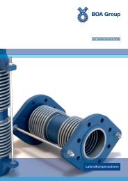
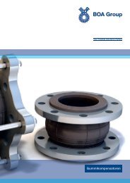
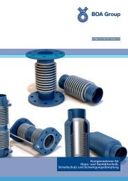
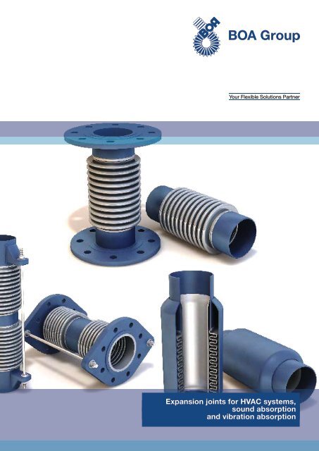
<strong>Expansion</strong> <strong>joints</strong> <strong>for</strong> <strong>HVAC</strong> <strong>systems</strong>,<br />
<strong>sound</strong> <strong>absorption</strong><br />
and vibration <strong>absorption</strong>
Table of<br />
Contents<br />
General<br />
<strong>Expansion</strong> <strong>joints</strong> 1<br />
Metal hoses 9<br />
Product portfolio overview<br />
Axial steel expansion <strong>joints</strong> 15<br />
Sound absorbing expansion <strong>joints</strong> 17<br />
Vibration absorbers 17<br />
Rubber expansion <strong>joints</strong> 19<br />
Metal hoses 24<br />
Technical data<br />
Axial steel expansion <strong>joints</strong> 25<br />
Sound absorbing expansion <strong>joints</strong> 44<br />
Vibration absorbers 45<br />
Rubber expansion <strong>joints</strong> 48<br />
Metal hoses 64<br />
Installation instructions<br />
Steel expansion <strong>joints</strong> 68<br />
Rubber expansion <strong>joints</strong> 78<br />
Metal hoses 86<br />
Application examples 92<br />
<strong>Expansion</strong> joint data sheet 95
General<br />
expansion <strong>joints</strong><br />
Depending on their physical properties,<br />
most materials expand when their temperature<br />
is increased and contract when the<br />
temperature falls.<br />
In pipe <strong>systems</strong>, this process is essentially<br />
made apparent by length changes in the<br />
individual pipe runs.<br />
As, in general, pipes are fixed at at least<br />
two connection points, reactions to inhibited<br />
thermal expansion inevitably occur, with<br />
a corresponding increase in stresses in the<br />
material and reaction <strong>for</strong>ces at the connection<br />
points.<br />
If the boundary conditions allow, in general<br />
an attempt is made to absorb the pipe<br />
expansion, i.e. to naturally compensate <strong>for</strong><br />
the expansion, by elastic (flexible) laying in<br />
the system.<br />
If all natural expansion compensation options<br />
have been exhausted, expansion <strong>joints</strong><br />
are provided to absorb length changes.<br />
In addition, if compressors, pumps, turbines<br />
or motors are operated, the resulting<br />
mechanical vibrations must be absorbed to<br />
prevent damage to the connected pipes,<br />
valves, fittings and supporting structures.<br />
Also, the allowable <strong>for</strong>ces and moments<br />
must not be exceeded at the nozzles of<br />
compressors, turbines, tanks and columns.<br />
<strong>Expansion</strong> <strong>joints</strong> are used <strong>for</strong> the application<br />
cases named above.<br />
The heart of each expansion joint is the<br />
metal bellows (*), which has a convoluted<br />
geometry and thin walled design that enable<br />
it to act as a spring, although it must fulfil<br />
the following basic conditions in order to<br />
be used as an expansion element:<br />
It must<br />
– withstand the operating and test conditions<br />
(pressure, temperature) of the pipe<br />
system,<br />
– be resistant to corrosion caused by internal<br />
and external influences,<br />
– be able to absorb expansions and possibly<br />
vibrations flexibly and achieve a<br />
required life expectancy,<br />
– have adequate buckling stability.<br />
<strong>Expansion</strong> compensation<br />
in pipes<br />
(*) Rubber expansion <strong>joints</strong> with their particular<br />
conditions of use constitute an exception.<br />
1
General<br />
expansion <strong>joints</strong><br />
Axial expansion <strong>joints</strong><br />
FP<br />
FL<br />
FL<br />
D<br />
9<br />
FP<br />
FL<br />
FL<br />
8<br />
7<br />
FP<br />
FL<br />
FP<br />
FL<br />
FP<br />
FL<br />
FL<br />
FL<br />
6<br />
5<br />
4<br />
3<br />
2<br />
1<br />
FP<br />
E<br />
FP<br />
Pump<br />
FP<br />
K<br />
Axial expansion <strong>joints</strong> are suitable <strong>for</strong> absorbing<br />
axial expansions (lengthening) in<br />
straight lengths of pipes.<br />
In addition, axial expansion <strong>joints</strong> are used<br />
Versatile and multi-purpose use of axial<br />
expansion <strong>joints</strong> requires appropriate fixed<br />
points and axial guide supports to be present.<br />
– to absorb vibrations and reduce structure-borne<br />
noise in pumps and compressors<br />
– as flexible gaskets at the end of jacketed<br />
pipes in district heating <strong>systems</strong><br />
– in flue gas conduits of boilers and<br />
motors, <strong>for</strong> thermal expansion and vibrations<br />
– as a disassembly joint at pumps, valves<br />
and plate heat exchangers<br />
– <strong>for</strong> gas-tight wall penetrations of pipes in<br />
nuclear reactor construction, shipbuilding<br />
2<br />
– in tank and apparatus construction <strong>for</strong><br />
absorbing differential expansion that<br />
occurs
General<br />
expansion <strong>joints</strong><br />
Anchor point Guide support Guide support Anchor point Guide support<br />
Anchor point Guide support Guide support Guide support Guide support Anchor point<br />
Anchor point Guide support Guide support Intermediate Guide support Guide support Anchor point<br />
anchor point<br />
Anchor point<br />
Guide support<br />
Guide support<br />
Guide support<br />
Anchor point<br />
Guide support<br />
Guide support<br />
Anchor point Guide support Guide support Guide support<br />
Anchor point<br />
3
General<br />
expansion <strong>joints</strong><br />
Inner sleeves<br />
If high-frequency vibrations, turbulence or<br />
high flow velocities are to be expected in<br />
the fluid, we recommend the installation of<br />
expansion <strong>joints</strong> with inner sleeve.<br />
The enclosed diagram: “Guideline <strong>for</strong> the<br />
use of an inner sleeve”, shows the limit curves<br />
<strong>for</strong> steam and gas and <strong>for</strong> liquids,<br />
above which use of inner sleeves is absolutely<br />
recommended.<br />
Use of inner sleeves helps to protect the bellows<br />
and reduces its flow-induced vibrational<br />
excitation and deposits and wear.<br />
Flow velocity v [m/s]<br />
10<br />
9<br />
8<br />
7<br />
6<br />
5<br />
4<br />
3<br />
2<br />
1<br />
Steam / gas<br />
Liquid<br />
0<br />
50 100 150 200 250 300<br />
Nominal size DN<br />
Determination<br />
of pipe expansion<br />
The expansion (movement) to be taken up<br />
by the individual expansion <strong>joints</strong> must be<br />
determined on the basis of the pipe layout,<br />
the pipe lengths and the operating temperature.<br />
Depending on the expansion joint type,<br />
axial or lateral movements can be absorbed.<br />
For precise determination of the movements<br />
that occur, especially if temperatureresistant<br />
and stainless pipe materials are<br />
used, it is recommended that the following<br />
<strong>for</strong>mula be used <strong>for</strong> the calculation:<br />
Ro = Lo · t · [mm]<br />
100<br />
Ro = calculated pipe movement (mm)<br />
L o = Length of pipe between the anchor<br />
points (m)<br />
t = temperature difference<br />
= temperature coefficient<br />
Temperature coefficient α<br />
For<br />
temperatures<br />
from<br />
[ o C]<br />
Temperature<br />
resistant pipe<br />
steels<br />
Austenite<br />
1.4541/1.4878<br />
Austenite<br />
1.4571<br />
–190 to 0 –0.88 –1.42 –1.46<br />
0 to 100 1.11 1.64 1.68<br />
0 to 200 1.21 1.71 1.75<br />
0 to 300 1.29 1.76 1.80<br />
0 to 400 1.35 1.80 1.84<br />
0 to 500 1.39 1.83 1.88<br />
0 to 600 1.43 1.86 1.91<br />
<strong>Expansion</strong> diagram<br />
<strong>for</strong> pipes made of<br />
mild steel<br />
220<br />
200<br />
Temperature difference [ C]<br />
50 100 150 200 250<br />
°<br />
300<br />
350<br />
400<br />
450<br />
500<br />
Length of the pipe [m]<br />
50<br />
40<br />
30<br />
20<br />
10<br />
4<br />
5<br />
10 20 30 40 50 100 200 300 400 500 800<br />
<strong>Expansion</strong> of the pipe [mm]
General<br />
expansion <strong>joints</strong><br />
The task of anchor points in pipes is to<br />
safely and reliably absorb the <strong>for</strong>ces that<br />
occur in the pipe and to assign the thermal<br />
expansion to the individual pipe sections.<br />
The main stresses and loads, which have<br />
to be absorbed by the anchor points if unrestrained<br />
expansion <strong>joints</strong> are:<br />
1. Pressure thrust F DR<br />
2. Bellows’ inherent resistance F E<br />
3. Frictional <strong>for</strong>ces F LR<br />
Re 1.<br />
The pressure thrust tries to pull the expansion<br />
joint bellows apart. As, in almost all<br />
cases, the pressure thrust is far larger than<br />
the bellows’ inherent resistance, it is not<br />
possible <strong>for</strong> equilibrium to be achieved between<br />
the bellows’ inherent resistance and<br />
the pressure thrust.<br />
Without appropriate anchor points, this<br />
would cause overstretching and there<strong>for</strong>e<br />
the destruction of the bellows. The pressure<br />
thrust (also called pressure reaction<br />
<strong>for</strong>ce) is calculated from the product of the<br />
bellows’ cross-sectional area and the pressure.<br />
Re 3.<br />
The pipe’s frictional <strong>for</strong>ces depend on the<br />
pipe weight including the fluid it carries,<br />
insulation and the coefficient of friction of<br />
the pipe support. Empirical values <strong>for</strong> pipe<br />
guide friction values μ LR:<br />
Steel/Steel 0.15–0.5<br />
Steel/PTFE 0.1 –0.25<br />
Roller bearing 0.03–0.1<br />
F LR = 9.81 · G LR · μ LR [N]<br />
The largest proportion of the <strong>for</strong>ce on the<br />
anchor point, where axial expansion <strong>joints</strong><br />
are used, comes from the pressure thrust.<br />
Axial expansion <strong>joints</strong> introduce an elastic<br />
or flexible interruption <strong>for</strong> the pipe, with<br />
which, as a result of the prevailing operating<br />
pressure in the pipe, the pressure<br />
thrust is released and has to be absorbed<br />
by suitable anchor points (Fig. 1).<br />
Anchor load<br />
F DR = 10 · p · A B [N]<br />
Re 2.<br />
The bellows’ own resistance is the <strong>for</strong>ce,<br />
which the bellows resist lengthening<br />
(extension) or shortening (compression).<br />
The specific inherent resistance of the bellows<br />
per + / - 1 mm extension is given in the<br />
technical tables as the spring characteristic<br />
c ax [N/mm].<br />
F E = c ax · ∆ ax [N]<br />
p<br />
p<br />
F H<br />
p<br />
F H<br />
Fig. 1<br />
5
General<br />
expansion <strong>joints</strong><br />
Anchor load<br />
A differentiation is made between the main<br />
anchors and intermediate anchors.<br />
Main anchors are always found at the start<br />
and end of the pipe and at bends (change of<br />
direction of the pipe) and branches, i.e.<br />
where the full reaction <strong>for</strong>ces occur (Fig. 2).<br />
F H = F DR + F E + F LR [N]<br />
F H p F ZW p F H<br />
Fig. 2<br />
The pressure thrust is practically removed<br />
from the intermediate anchors and axially<br />
these only absorb the inherent resistance<br />
of the expansion joint and the friction <strong>for</strong>ces<br />
from the pipe guides.<br />
Note:<br />
F ZW = F E + F LR [N]<br />
If, <strong>for</strong> structural or space reasons, it is not<br />
possible to set any anchors, restrained<br />
expansion <strong>joints</strong> must be used.<br />
A B = bellows effective area [cm 2 ]<br />
c ax = axial spring rate [N/mm]<br />
F DR = pressure thrust [N]<br />
F E = bellows’ inherent resistance [N]<br />
F LR = pipe friction <strong>for</strong>ce [N]<br />
F H = main anchor load [N]<br />
F ZW = intermediate anchor load [N]<br />
p = design or test overpressure<br />
[bar]<br />
= pipe movement that occurs [mm]<br />
G LR = pipe weight [kg]<br />
μ LR = coefficient of bearing friction [–]<br />
6
General<br />
expansion <strong>joints</strong><br />
In the context of <strong>sound</strong> insulation and vibration<br />
absorbers, mechanical vibrations are<br />
within the frequency range up to the audible<br />
limit (Fig. 1).<br />
Mechanical vibrations are generated in<br />
units and are transmitted through the fluid,<br />
but mainly through the pipe, in the entire<br />
pipe system.<br />
The vibrations propagated in this way are<br />
perceived on the one hand as annoying<br />
noise, and on the other hand they cause<br />
large stresses in the materials subjected to<br />
the vibrations.<br />
In the case of pipes laid without <strong>sound</strong> insulation<br />
and/or vibration absorbers, fractures<br />
and failures can very soon occur, which<br />
endanger the operating safety and economic<br />
efficiency of a plant or installation.<br />
Vibrations<br />
Range of mechanical vibrations<br />
Lower<br />
audible limit<br />
16 Hz<br />
Standard<br />
pitch<br />
440 Hz<br />
Upper<br />
audible limit<br />
20.000 Hz<br />
Earthquakes<br />
Ground<br />
vibrations<br />
Infra<strong>sound</strong><br />
Piano<br />
Audible <strong>sound</strong><br />
10 -2 10 -1 10 0 10 1 10 2 10 3 10 4 10 5 10 6 10 7<br />
Frequency in Hz<br />
Fig. 1<br />
Vibration absorbers / <strong>sound</strong> absorbing expansion<br />
<strong>joints</strong> are very flexible pipe elements,<br />
which thanks to their flexible structure, are<br />
able to remove part of the energy from a vibrating<br />
system. Fig. 2 shows the oscillogram of an<br />
absorbed vibration that has occurred in this<br />
way.<br />
Vibration absorbers /<br />
<strong>sound</strong> absorbing<br />
expansion <strong>joints</strong><br />
Use of austenitic steels and elastomers of<br />
different quality ideally fulfils the highest<br />
requirements with regard to:<br />
Fig. 2<br />
– Pressure<br />
– Temperature<br />
– Corrosion<br />
– Long life expectancy<br />
Operating temperatures from –10 °C to<br />
200°C and nominal pressures from PN 6 to<br />
PN 16 in the standard types can be easily<br />
covered.<br />
Special types are possible <strong>for</strong> higher pressures<br />
and temperatures.<br />
7
General<br />
expansion <strong>joints</strong><br />
Low-noise plant<br />
By choosing the right expansion joint and<br />
its optimum positioning see installation<br />
instructions), you have taken the most<br />
important measures to prevent the propagation<br />
of vibrations in the pipe system.<br />
However, to achieve the objective of lownoise<br />
plant, the following problem areas<br />
must also be solved:<br />
The vibration source<br />
When choosing the unit, attention must be<br />
paid to the most quietly and smoothly running<br />
appliance.<br />
Fig. 3<br />
Transfer to the building or engineering<br />
structure<br />
Units, which generate mechanical vibrations<br />
transfer them to the building as structure-borne<br />
<strong>sound</strong>. Flawless structure-borne<br />
<strong>sound</strong> insulation is indispensible <strong>for</strong> all<br />
these devices (see Fig. 3).<br />
If there is a high airborne <strong>sound</strong> level in the<br />
room, there is a risk of the pipes, vessels,<br />
tanks, boiler plants and even the building<br />
structure becoming excited. In this case,<br />
the unit must be clad, or the room must be<br />
clad with <strong>sound</strong>-absorbing materials (Fig.<br />
4).<br />
Fig. 4<br />
8
General metal<br />
hoses<br />
The range of metal hoses kept in stock<br />
includes all products in the standard diameters,<br />
dimensions and materials, which are<br />
used in<br />
Gas installation<br />
Heating installation<br />
Cooling <strong>systems</strong><br />
Sanitary installation<br />
Solar engineering<br />
Steam supply<br />
Fire safety engineering<br />
Air conditioning<br />
and similar industries.<br />
Application<br />
Allowable operating temperatur t B [°C]:<br />
Operating temperature of a hose assembly,<br />
which results from the max. allowable operating<br />
temperature of the weakest component<br />
or the weakest connection.<br />
Temperature factor t P:<br />
Factor <strong>for</strong> reduction of the allowable operating<br />
pressure. It corrects the allowable calculated<br />
strength of the metal hose material<br />
depending on the material used and the<br />
design temperature.<br />
Burst pressure p R [bar]:<br />
Maximum inner overpressure, which is reached<br />
be<strong>for</strong>e a component bursts.<br />
Nominal pressure PN:<br />
The nominal pressure level rounded down<br />
according to EN 1333, which results from<br />
the max. allowable design pressure.<br />
Dynamic design pressure p B dyn. [bar]:<br />
Allowable operating pressure of a metal<br />
hose made of the standard material 1.4571<br />
at 20 °C and a dynamic load of 50 000 load<br />
cycles according to ISO 10380 (see also<br />
“Life expectancy” section)<br />
Static design pressure p B [bar]:<br />
Allowable operating pressure of a metal<br />
hose made of the standard material 1.4571<br />
at 20 °C, <strong>for</strong> use without cyclical movements,<br />
calculated as 1/4 of the burst pressure<br />
Test pressure p P [bar]:<br />
Overpressure, which a hose assembly is<br />
exposed to in order to check its compressive<br />
strength.<br />
Allowable operating pressure p B [bar]:<br />
Operating pressure of a hose assembly,<br />
which results from the dynamic or static<br />
design pressure or the maximum allowable<br />
operating pressure of a hose fitting or its<br />
joining methods – whichever value is the<br />
lower – reduced by the temperature factor<br />
tP corresponding to the operating temperature<br />
and the reduction factor D P, which<br />
depends on the type of operation.<br />
Bend radius R [mm]:<br />
Radius of the circular arc of corrugated<br />
metal hose, relative to the hose axis.<br />
Minimum bend radius R min [mm]:<br />
Bend radius <strong>for</strong> one-off movement. The<br />
bend radius must not be below the specified<br />
minimum.<br />
Nominal bend radius R N [mm]:<br />
Dynamic bend radius <strong>for</strong> frequent movement<br />
according to ISO 10380. Undergoing<br />
the nominal bending radius reduces the life<br />
expectancy of the metal hose assembly.<br />
Torsion:<br />
Twisting of the corrugated metal hose around<br />
its own axis. Torsion results in premature<br />
failure of the metal hose assembly.<br />
Life expectancy:<br />
The life expectancy of a hose under dynamic,<br />
i.e. under constantly recurring movement<br />
is determined using the method<br />
described in the international “ISO 10380”<br />
standard. With this method, the hose<br />
assembly in the U-bend position nominal<br />
bend radius RN and vertical movement<br />
(see also page 12) under design pressure,<br />
must withstand 10000 load cycles without<br />
leaking.<br />
Metal hoses are tested using this method,<br />
and the dynamic bend radii given in column<br />
RN of the technical tables meet these<br />
requirements.<br />
In case of higher numbers of load cycles<br />
the allowable bend radius must be increased.<br />
Vice versa, a smaller bend radius<br />
reduces the expected number of load<br />
cycles.<br />
Pressure loss:<br />
Due to their convoluted (corrugated) profile,<br />
metal hose assemblies have a higher resistance<br />
to flow than smooth pipes. Here the<br />
nominal size, fluid and flow rate play a role.<br />
In the case of short hose assemblies, this<br />
pressure loss can be ignored; however, it<br />
should be checked <strong>for</strong> longer lengths.<br />
Definition of terms<br />
used<br />
9
General metal<br />
hoses<br />
Allowable operating<br />
pressure p B<br />
The design pressure given in the technical<br />
tables relates to a temperature of 20 °C. At<br />
higher operating temperatures, due to the<br />
drop in strength of the hose materials, the<br />
allowable operating pressure p B must be<br />
reduced by the respective temperature factor<br />
t P given in the following table.<br />
Effect of the operating<br />
temperature<br />
Temperature reduction factors t P<br />
Temp. 20 50 100 150 200 250 300 350 400 450 500 550 600 650<br />
[°C]<br />
1.4301<br />
ISO 11<br />
1 0.93 0.81 0.70 0.64 0.60 0.57 0.54 0.52 0.51 0.50 0.49 0.47 0.19<br />
1.4541<br />
ISO 15<br />
1 0.94 0.86 0.76 0.73 0.70 0.67 0.65 0.63 0.61 0.60 0.59 0.57 0.19<br />
1.4404<br />
ISO 19<br />
1 0.93 0.83 0.72 0.66 0.62 0.59 0.56 0.55 0.53 0.51 0.50 0.50<br />
1.4435<br />
ISO 19 a<br />
1 0.93 0.83 0.72 0.66 0.62 0.59 0.56 0.55 0.53 0.51 0.50 0.50<br />
1.4571<br />
ISO 21<br />
1 0.94 0.84 0.75 0.69 0.65 0.62 0.60 0.58 0.56 0.54 0.53 0.52<br />
Effect of the type of<br />
operation<br />
If hose assemblies are installed in operating<br />
<strong>systems</strong> in which pressure shocks,<br />
strong pressure pulsations or sudden<br />
movements occur, the allowable operating<br />
pressure must be adjusted by a further factor<br />
D P.<br />
Reduction factor D P<br />
allowable operating<br />
pressure p B<br />
p B = design pressure · t P · D P [bar]<br />
Uni<strong>for</strong>m, frequent Sudden movements,<br />
movements, vibrations vibrations with large<br />
with small amplitudes amplitudes<br />
Uni<strong>for</strong>m flow 1.0 0.8<br />
Pulsating,<br />
non-uni<strong>for</strong>m flow<br />
0.8 0.5<br />
Pressure shocks,<br />
pulsating flow<br />
0.5 0.35<br />
Determination of the<br />
Allowable test pressure:<br />
1.5 · design pressure<br />
10
General metal<br />
hoses<br />
Straight metal hose assembly <strong>for</strong> parallel displacement<br />
(Movements transversely to the hose plane are not allowed)<br />
Type of installation:<br />
Application:<br />
Formula:<br />
straight hose assembly<br />
lateral displacement<br />
Not suitable <strong>for</strong> recurring movements!<br />
cos α = 1 – a / (2 · R N)<br />
System calculations<br />
Installation <strong>for</strong> oneoff<br />
bending (to compensate<br />
<strong>for</strong> parallel<br />
pipe misalignments)<br />
cos α may not be 0.5, otherwise<br />
radius R > R N must be chosen.<br />
NL = 0.035 · R N · α + 2 · DN + 2 · l<br />
EL = 2 · R N · sin α + 2 · DN + 2 · l<br />
Straight metal hose assembly <strong>for</strong> lateral movements<br />
(Movements transversely to the hose plane are not allowed)<br />
Installation <strong>for</strong> lateral<br />
movement capacity<br />
Type of installation:<br />
straight hose assembly<br />
Application:<br />
Formula:<br />
lateral displacement<br />
– large amplitudes<br />
– low stroke frequency<br />
NL = 4.5 · √ R N · s + 2 · DN + 2 · l<br />
2s s<br />
EL = ≈ NL · (1 – 0.15 · s / NL)<br />
Minimum hose length NL min. = 7 · s + 2 · l<br />
R N = dyn. nominal bend radius of the chosen<br />
hose type [mm]<br />
DN = nominal size<br />
a = displacement from the axis [mm]<br />
s = lateral movement capacity [mm]<br />
I = length of the hose fitting<br />
α = bend angle [°]<br />
NL = nominal length [mm]<br />
EL = built-in length [mm]<br />
11
General metal<br />
hoses<br />
Installation<br />
<strong>for</strong> absorbing vertical<br />
stroke movements<br />
U bends <strong>for</strong> vertical movement<br />
(movements across the hose plane are not allowed)<br />
Type of installation:<br />
vertical 180° bend<br />
Type of movement:<br />
Formulae :<br />
vertical stroke movement<br />
– large amplitudes<br />
– low stroke frequency<br />
NL = (2.5 · R N + s) · 1.57 + 2 · DN + 2 · l<br />
h 1<br />
h 2<br />
= R N + 0.785 · s + DN + l<br />
= R N + s / 2 + DN + l<br />
Installation<br />
<strong>for</strong> absorbing horizontal<br />
stroke movements<br />
U bends <strong>for</strong> vertical movement<br />
(movements across the hose plane are not allowed)<br />
Type of installation:<br />
vertical 180° bend<br />
Type of movement:<br />
vertical stroke movement<br />
– large amplitudes<br />
– low stroke frequency<br />
Formulae :<br />
NL<br />
h 1 max<br />
h 2 min<br />
= R N · + s / 2 + 2 · DN + 2 · l<br />
= R N + s / 2 + DN + l<br />
= R N + DN + l<br />
12<br />
R N = dyn. nominal bend radius of the<br />
chose hose type [mm]<br />
DN = nominal size<br />
I = length of the hose fitting<br />
h 1 = maximum height of the 180° bend<br />
[mm]<br />
h 2 = minimum height of the 180° bend<br />
[mm]<br />
s = movement [mm]<br />
NL = nominal length [mm]
General metal<br />
hoses<br />
U bends <strong>for</strong> vertical and horizontal movement<br />
(movements across the hose plane are not allowed)<br />
Type of installation:<br />
vertical 180° bend<br />
Installation <strong>for</strong> absorbing<br />
vertical and horizontal<br />
stroke movements<br />
Type of movement:<br />
vertical and horizontal stroke movement<br />
– large amplitudes<br />
– low stroke frequency<br />
Formulae:<br />
NL<br />
h 1 max<br />
h 2 min<br />
= 1.57 · (2 · R N + s 1) + s 2 / 2 + 2 · DN + l<br />
= R N + 0.785 · s 1 + s 2 / 2 + DN + l<br />
= R N + s 1 / 2 + DN + l<br />
90° metal hose assembly <strong>for</strong> lateral movement capacity<br />
(Movements across the hose plane are not allowed)<br />
Type of installation:<br />
90° hose assembly<br />
Installation <strong>for</strong> absorbing<br />
thermal expansion<br />
from one direction<br />
Type of movement:<br />
Formulae:<br />
lateral movement capacity in 1 axis<br />
– low amplitudes<br />
– low stroke frequency<br />
cos α = 1 – s / (2 · R N)<br />
NL<br />
a<br />
b<br />
= R N · (1.57 + 0.035 · α) + 2 · DN + 2 · I<br />
= R N + 2 · R N · sin α + DN + l<br />
= R N + R N · (0.035 · α – 2 · sin α) + DN + I<br />
The angle α must not exceed 60°!<br />
cos α must be ≥ 0.5,<br />
otherwise R > RN must be chosen<br />
R N = dyn. nominal bend radius of the<br />
chose hose type [mm]<br />
DN = nominal size<br />
a = installation distance [mm]<br />
b = installation distance [mm]<br />
h 1 = maximum height of the 180° bend<br />
[mm]<br />
h 2 = minimum height of the 180° bend<br />
[mm]<br />
s = movement capacity [mm]<br />
s 1 = horizontal stroke [mm]<br />
s 2 = vertical stroke [mm]<br />
l = length of the hose fitting<br />
α = bend angle [°]<br />
NL = nominal length [mm]<br />
13
General<br />
metal hoses<br />
Installation<br />
<strong>for</strong> absorbing thermal<br />
expansion from two<br />
directions<br />
990° hose assembly <strong>for</strong> movement capacity in 2 axes<br />
(movements across the hose plane are not allowed)<br />
Type of installation:<br />
90° hose assembly<br />
Type of movement:<br />
Formula:<br />
lateral movement capacity in 2 axes<br />
– low amplitudes<br />
– low stroke frequency<br />
cos α = 1 – s 1 / (2 · R N)<br />
cos β = 1 – s 2 / (2 · R N)<br />
NL = R N · (1.57 + 0.035 · α + 0.035 · β) + 2 · DN + 2 · I<br />
a<br />
b<br />
= R N + R N · (2 · sin α + 0.035 · β – 2 · sin β) + DN + l<br />
= R N + R N · (2 · sin β + 0.035 · α – 2 · sin α) + DN + l<br />
The angle α must not exceed 60°! cos α and cos β must be ≥ 0.5,<br />
otherwise R > RN must be chosen<br />
Installation<br />
and calculation<br />
<strong>for</strong> <strong>absorption</strong> of<br />
vibrations<br />
90° bend <strong>for</strong> absorbing vibrations<br />
Type of installation:<br />
Application:<br />
90° hose bend or 90° dog-leg<br />
All-round vibrations<br />
– small amplitudes<br />
– high stroke frequency<br />
Formula:<br />
NL<br />
c<br />
= 2 · R N + 2 · I<br />
= 1.27 · R N + I<br />
14<br />
R N = dyn. nominal bending radius<br />
R N = of the chosen hose type [mm]<br />
DN = nominal size<br />
a = installation distance [mm]<br />
b = installation distance [mm]<br />
c = side length [mm]<br />
s 1 = movement capacity [mm]<br />
s 2 = movement capacity [mm]<br />
l = length of the hose fitting<br />
α = bend angle [°]<br />
β = bend angle [°]<br />
NL = nominal length [mm]
Product portfolio<br />
overview<br />
Axial steel expansion joint<br />
Bellows made of 1.4571 (up to DN 50) or<br />
1.4541 (from DN 65), weld ends attached<br />
both sides made of mild steel Type BKT-<br />
7110 000 (old: 307/210) DN ...., PN ..., ax<br />
+/– ...., Bl ....<br />
Axial steel expansion joint<br />
Bellows made of 1.4571 (up to DN 50) or<br />
1.4541 (from DN 65), weld ends attached<br />
both sides made of 1.4571 Type BKT-7110<br />
00S-KW DN ...., PN ..., ax +/– ...., Bl ....<br />
Steel expansion <strong>joints</strong><br />
with weld ends<br />
Axial steel expansion joint<br />
Bellows made of 1.4571 (up to 50) or<br />
1.4541 (from DN 65), weld ends attached<br />
both sides made of mild steel, with inner<br />
sleeve and protective tube made of mild<br />
steel, suitable <strong>for</strong> ax without prestressing<br />
Type BKT-7119 00X (old: 307/224)<br />
DN ...., PN ..., ax ...., Bl ....<br />
Axial steel expansion joint<br />
Bellows made of 1.4571, weld ends attached<br />
both sides made of 1.4571, with inner<br />
sleeve and protective tube made of 1.4571<br />
or 1.4404, suitable <strong>for</strong> ax without prestressing<br />
Type BKT-7119 00S-KW DN ....,<br />
PN ..., ax ...., Bl ....<br />
Axial steel expansion joint<br />
Bellows made of 1.4571 (up to DN 50) or<br />
1.4541 (from DN 65), flange connection both<br />
sides made of mild steel Type BKT-7120<br />
000 (old: 307/211) DN ...., PN ..., ax +/– ....,<br />
Bl ....<br />
Axial steel expansion joint<br />
Bellows made of 1.4571 (up to DN 50) or<br />
1.4541 (from DN 65), flange connections<br />
both sides made of 1.4571 Type BKT-7120<br />
00S-KW DN ...., PN ..., ax +/– ...., Bl ....<br />
Steel expansion<br />
<strong>joints</strong> with flange<br />
connection<br />
Axial steel expansion joint<br />
Bellows made of 1.4571 (up to 50) or<br />
1.4541 (from DN 65), flange connections<br />
both sides made of mild steel, with inner<br />
sleeve and protective tube made of mild<br />
steel, suitable <strong>for</strong> ax without prestressing<br />
Type BKT-7129 00X (old: 307/225)<br />
DN ...., PN ..., ax ...., Bl ....<br />
Axial steel expansion joint<br />
Bellows made of 1.4571, flange connection<br />
both sides made of 1.4571, with inner sleeve<br />
and protective tube made of 1.4571 or<br />
1.4404, suitable <strong>for</strong> ax without prestressing<br />
Type BKT-7129 00S-KW DN ...., PN<br />
..., ax ...., Bl ....<br />
15
Product portfolio<br />
overview<br />
Steel expansion <strong>joints</strong><br />
<strong>for</strong> Mannesmann<br />
press fitting system<br />
Axial steel expansion joint with Mannesmann<br />
press fitting connector, bellows made<br />
of 1.4571, weld ends attached both sides<br />
with connector made of mild steel with inner<br />
sleeve and protective tube made of mild<br />
steel, suitable <strong>for</strong> ax without prestressing<br />
Type BKT-7179 00X-MS DN ...., PN ...,<br />
ax +/– ...., Bl ....<br />
Axial steel expansion joint with Mannesmann<br />
press fitting connector, bellows made<br />
of 1.4571, weld ends attached both sides<br />
with connector made of 1.4571 or 1.4404,<br />
with inner sleeve and protective tube<br />
made of 1.4571 or 1.4404 Type BKT-7179<br />
00X-ME DN ...., PN ..., ax +/– ...., Bl ....<br />
Steel expansion <strong>joints</strong><br />
with threaded sockets<br />
or soldering ends<br />
Axial steel expansion joint<br />
Bellows made of 1.4571, threaded sockets on<br />
both sides with protective tube suitable <strong>for</strong> ax<br />
without prestressing Type BKT-7162 00S (old:<br />
307/245)<br />
Connection<br />
DN ...., PN ..., ax ...., Bl ....<br />
TI (malleable cast iron, female<br />
thread) or<br />
RI (gunmetal, female thread) or<br />
TA (malleable cast iron/male<br />
thread) or<br />
RA (gunmetal/male thread)<br />
EI (stainless steel/female<br />
thread)<br />
LF (soldering fitting)<br />
Axial steel expansion joint<br />
Bellows made of 1.4571, threaded sockets on<br />
both sides suitable <strong>for</strong> ax without prestressing<br />
Type BKT-7160 00S (old: 307/243)<br />
Connection TI (malleable cast iron, female<br />
thread) or<br />
RI (gunmetal, female thread)<br />
or<br />
TA (malleable cast iron/male<br />
thread) or<br />
RA (gunmetal/male thread)<br />
EI (stainless steel/female<br />
thread)<br />
LF (soldering fitting)<br />
DN ...., PN ..., ax ...., Bl ....<br />
Bellows made of bronze, soldering ends on<br />
both sides made of copper with external<br />
sleeve made of copper, prestressed<br />
Type <strong>BOA</strong>-I DN ...., PN ..., ax ...., Bl ....<br />
16
Product portfolio<br />
overview<br />
Axial steel expansion joint<br />
Bellows and collar made of 1.4571 (up to<br />
DN 50) or 1.4541 (from DN 65), loose flange<br />
both sides made of mild steel<br />
Type BKT-7150 000 (old: 307/241)<br />
DN ...., PN ..., ax +/– ...., Bl ....<br />
Steel expansion <strong>joints</strong><br />
with loose flanges<br />
Sound absorbing expansion joint<br />
Bellows and collar made of 1.4571 (up to<br />
DN 50) made of 1.4541 (from DN 65), loose<br />
flange both sides made of mild steel, with<br />
inner sleeve made of wire mesh (up to DN<br />
150)<br />
Type BKT-7951 00S (old: 303/445)<br />
DN ...., PN ..., ax +/– ...., Bl ....<br />
Sound absorbing<br />
expansion <strong>joints</strong> and<br />
vibration absorbers<br />
Sound absorbing expansion joint<br />
Bellows and collar made of 1.4571 (up to<br />
DN 50), made of 1.4541 (from DN 65),<br />
loose flange both sides. Loose flange made<br />
of mild steel, with tie rod restraint made of<br />
mild steel, with inner sleeve made of wire<br />
mesh (up to DN 150) only <strong>for</strong> vibration<br />
<strong>absorption</strong><br />
Type BKT-7951 DFS (old: 303/487)<br />
DN ...., PN ..., Bl ....<br />
Vibration absorbers<br />
Bellows and collar made of 1.4571, loose<br />
flange both sides made of mild steel<br />
Type <strong>BOA</strong>-ALPHA C<br />
DN ...., PN ..., Bl ....<br />
Vibration absorbers<br />
Bellows and collar made of 1.4571, loose<br />
flange both sides made of mild steel with<br />
tie-rod restraint made of mild steel<br />
Type <strong>BOA</strong>-EPSILON C<br />
DN ...., PN ..., Bl ....<br />
17
Product portfolio<br />
overview<br />
Vibration absorbers<br />
Vibration absorbers<br />
Pliable tubing made of CuSn 6, braid<br />
made of 1.4301, soldering ends made of<br />
copper<br />
Type <strong>BOA</strong>-OMIKRON<br />
DN . . . . , PN . . ., BI . . .<br />
Vibration absorbers<br />
Pliable tubing made of 1.4541, braid and<br />
end sleeves made of 1.4301, threaded<br />
coupling made of malleable cast iron<br />
Types <strong>BOA</strong>-JOTA and <strong>BOA</strong>-KAPPA<br />
DN . . . . , PN . . ., BI . . .<br />
Vibration absorbers<br />
Pliable tubing made of 1.4541, braid and<br />
end sleeves made of 1.4301, lapped pipe<br />
end made of 1.4571 Loose flanges made<br />
of St 37-2<br />
Types <strong>BOA</strong>-SIGMA and <strong>BOA</strong>-OMEGA<br />
DN . . . . , PN . . ., BI . . .<br />
18
Product portfolio<br />
overview<br />
Rubber expansion joint<br />
Bellows inner ply 1) , nylon cord rein<strong>for</strong>cement,<br />
threaded sockets on both sides<br />
made of GGG-40, zinc-plated<br />
Type BKT-3160 00S-B –. . . 1)<br />
DN . . . . , PN . . .<br />
Rubber expansion<br />
valves with threaded<br />
sockets<br />
1) EPDM<br />
Rubber expansion joint<br />
Bellows inner ply 1) , nylon cord rein<strong>for</strong>cement,<br />
threaded sockets on both sides<br />
made of GGG-40, zinc-plated<br />
Type BKT-3160 00S-A –. . . 1)<br />
DN . . . . , PN . . .<br />
1) EPDM<br />
EPDMT<br />
CHLOROPREN<br />
NITRIL<br />
EPDM-SAN<br />
Rubber expansion joint<br />
Bellows inner ply 1) , nylon cord rein<strong>for</strong>cement,<br />
threaded sockets on both sides<br />
made of GGG-40, zinc-plated<br />
Type BKT-3160 00S-D –. . . 1)<br />
DN . . . . , PN . . .<br />
1) EPDM<br />
EPDMT<br />
CHLOROPREN<br />
NITRIL<br />
EPDM-SAN<br />
19
Product portfolio<br />
overview<br />
Rubber expansion<br />
valves with flange<br />
connection<br />
Rubber expansion joint<br />
Bellows inner ply 1) , nylon cord rein<strong>for</strong>cement,<br />
loose flanges on both sides made of<br />
mild steel, zinc-plated<br />
Type BKT-3140 00S-B –. . . 1)<br />
(old: 303/441) DN . . . . , PN . . .<br />
1) EPDM<br />
Rubber expansion joint<br />
Bellows inner ply 1) , aramide rein<strong>for</strong>cement,<br />
loose flange on both sides made of mild<br />
steel, zinc plated, TÜV tested to DIN 4809<br />
Type BKT-3140 00S-S –. . . 1)<br />
DN . . . . , PN . . .<br />
1) EPDMT<br />
Rubber expansion joint<br />
Bellows inner ply 1) , nylon cord rein<strong>for</strong>cement,<br />
loose flanges on both sides made of mild<br />
steel, zinc-plated<br />
Type BKT-3140 00S-A –. . . 1) (old: 313/441)<br />
DN . . . . , PN . . .<br />
1) EPDM<br />
EPDMT<br />
CHLOROPREN<br />
NITRIL<br />
HYPALON<br />
EPDM-SAN<br />
Rubber expansion joint<br />
Bellows inner ply 1) , nylon cord rein<strong>for</strong>cement,<br />
loose flanges on both sides made of<br />
mild steel, zinc-plated<br />
Type BKT-3140 00S-D –. . . 1)<br />
DN . . . . , PN . . .<br />
1) EPDM<br />
EPDMT<br />
CHLOROPREN<br />
NITRIL<br />
HYPALON<br />
EPDM-SAN<br />
20
Product portfolio<br />
overview<br />
Rubber expansion joint<br />
Bellows inner ply 1) , nylon cord rein<strong>for</strong>cement,<br />
loose flanges on both sides made of<br />
mild steel, zinc-plated, with noise-insulated<br />
supported tie-rod restraint made of mild<br />
steel, zinc-plated<br />
Type BKT-3840 DFS-B –. . . 1)<br />
(old: 303/485)<br />
DN . . . . , PN . . .<br />
Rubber expansion<br />
<strong>joints</strong> with flange<br />
connection and tie-rod<br />
restraint<br />
1) EPDM<br />
Rubber expansion joint<br />
Bellows inner ply 1) , aramide rein<strong>for</strong>cement,<br />
loose flanges on both sides made of mild<br />
steel, zinc-plated, with noise-insulated supported<br />
tie-rod restraint made of mild steel,<br />
zinc-plated TÜV-tested to DIN 4809 Type<br />
BKT-3840 DFS-S –. . . 1)<br />
DN . . . . , PN . . .<br />
1) EPDMT<br />
Rubber expansion joint<br />
Bellows inner ply 1) , nylon cord rein<strong>for</strong>cement,<br />
loose flanges on both sides made of<br />
mild steel, zinc-plated, with noise-insulated<br />
supported tie-rod restraint made of mild<br />
steel, zinc-plated<br />
Type BKT-3840 DFS-A –. . . 1)<br />
(old: 313/485)<br />
DN . . . . , PN . . .<br />
1)<br />
EPDM<br />
EPDMT<br />
CHLOROPREN<br />
NITRIL<br />
HYPALON<br />
EPDM-SAN<br />
Rubber expansion joint<br />
Bellows inner ply 1) , nylon cord rein<strong>for</strong>cement,<br />
loose flanges on both sides made of<br />
mild steel, zinc-plated, with noise-insulated<br />
supported tie-rod restraint made of mild<br />
steel, zinc-plated<br />
Type BKT-3840 DFS-D –. . . 1)<br />
DN . . . . , PN . . .<br />
1)<br />
EPDM<br />
EPDMT<br />
CHLOROPREN<br />
NITRIL<br />
HYPALON<br />
EPDM-SAN<br />
Rubber/metal pipe joint<br />
Rubber body made of EPDM with vulcanised<br />
steel flanges made of<br />
St 37-2<br />
suitable <strong>for</strong> noise reduction<br />
Type IGMV<br />
DN . . . . , PN . . .<br />
21
Product portfolio<br />
overview<br />
Rubber expansion<br />
<strong>joints</strong><br />
Materials<br />
The bellows of the rubber expansion <strong>joints</strong><br />
are made of elastomers – inner and outer<br />
layer – with several continuous nylon cord<br />
mesh inlays.<br />
The nylon cord fabric inlays ensure high<br />
strength and resistance to the internal pressure<br />
and vacuum.<br />
The rubber expansion <strong>joints</strong> with bellows<br />
types A, B, D + S can be fitted with loose<br />
flanges, bellows types A, B + D can also be<br />
fitted with threaded sockets. In the type with<br />
loose flanges, the toric rims of the bellows,<br />
rein<strong>for</strong>ced by steel inlays, act as a gasket.<br />
Bellows A (313) + Bellows D (323)<br />
Type A (313)<br />
Type D (323)<br />
Colour<br />
marking<br />
black<br />
(dot)<br />
red<br />
(circle)<br />
red<br />
(dot)<br />
yellow/white<br />
(dot)<br />
red/blue<br />
(dot)<br />
green<br />
(dot)<br />
Fluid*) Structure Material<br />
– hot and cold water<br />
– water with low chemical<br />
additives<br />
– Hot water<br />
Type test to DIN 4809<br />
– Acidic water<br />
– Wastewater<br />
– Hot water<br />
– Oils<br />
– Fuels<br />
– Gases<br />
– Drinking water<br />
– Cold water<br />
– Chemicals<br />
Inner ply<br />
Rein<strong>for</strong>cement<br />
Outer ply<br />
Inner ply<br />
Rein<strong>for</strong>cement<br />
Outer ply<br />
Inner ply<br />
Rein<strong>for</strong>cement<br />
Outer ply<br />
Inner ply<br />
Rein<strong>for</strong>cement<br />
Outer ply<br />
Inner ply<br />
Rein<strong>for</strong>cement<br />
Outer ply<br />
Inner ply<br />
Rein<strong>for</strong>cement<br />
Outer ply<br />
*) Basic recommendation, in case of doubt refer to the list of resistances.<br />
Chloroprene<br />
Nylon cord<br />
Chloroprene<br />
EPDMT<br />
Nylon cord Spec.<br />
EPDMT<br />
EPDM<br />
Nylon cord<br />
EPDM<br />
Nitrile<br />
Nylon cord<br />
Chloroprene<br />
EPDM-SAN<br />
Nylon cord<br />
EPDM-SAN<br />
Hypalon<br />
Nylon cord<br />
Chloroprene<br />
Type S (333)<br />
Bellows S (333)<br />
Colour<br />
marking<br />
red<br />
(circle)<br />
Fluid Structure Material<br />
– Hot water<br />
Type test to DIN 4809<br />
Inner ply<br />
Rein<strong>for</strong>cement<br />
Outer ply<br />
EPDMT<br />
ARAMID<br />
EPDM<br />
22
Product portfolio<br />
overview<br />
Bellows B (303)<br />
Colour<br />
marking<br />
Fluid*) Structure Material<br />
Inner ply<br />
PTFE<br />
brown – universell<br />
Rein<strong>for</strong>cement Nylon cord<br />
Outer ply<br />
Chloroprene<br />
– Acidic water<br />
Inner ply<br />
EPDM<br />
red – Wastewater<br />
Rein<strong>for</strong>cement Nylon cord<br />
– Hot water<br />
Outer ply<br />
EPDM<br />
*) Basic recommendation, in case of doubt refer to the list of resistances.<br />
Rubber expansion<br />
<strong>joints</strong><br />
Materials<br />
Type B (303)<br />
Rubber / metal pipe joint – IGMV –<br />
Fluid*) Structure Material<br />
– Hot water<br />
Type test, TÜV Southern<br />
Germany<br />
– Hot and cold water<br />
Rubber body<br />
EPDM<br />
Steel flanges, St 37-2<br />
vulcanised<br />
Type IGMV<br />
Threaded sockets<br />
made of GGG 40 – zinc-plated<br />
Flanges<br />
made of carbon steel, zinc-plated, connection<br />
dimensions to DIN EN 1092-1 with<br />
threaded holes.<br />
Other materials and dimensions available on<br />
request.<br />
Restraint<br />
Hexagon bolts or threaded rods and clamping<br />
nuts made of mild steel, galvanised.<br />
The expansions (movements) listed in the<br />
table are either axial or lateral or angular<br />
movement capacity.<br />
If combined movements occur (e.g. axial<br />
and lateral), the sum of the percentage individual<br />
shares of the movements must not<br />
exceed 100 %.<br />
The following movement capacities are<br />
allowed in combination:<br />
– ax drawn with lateral or<br />
– ax drawn with angular movement.<br />
Δax (expanded)<br />
100 %<br />
80 %<br />
60 %<br />
40 %<br />
20 %<br />
Allowable movement<br />
20 % 40 % 60 % 80 % 100 %<br />
Δ lat. or Δ ang.<br />
Example:<br />
Type BKT-3140 00S-A –. . ., DN 200<br />
ax = 7 mm drawn ^= 35 %<br />
allowable lateral proportion there<strong>for</strong>e<br />
65 % ^= lat = ± 9.75 mm<br />
23
Product portfolio<br />
overview<br />
Metal hoses<br />
Metal hose assembly<br />
Corrugated metal hose made of 1.4541,<br />
Braid made of 1.4301<br />
Annularly corrugated hose assembly<br />
SP 10<br />
DN . . . . , PN . . .<br />
Metal hose assembly<br />
Corrugated metal hose made of 1.4541,<br />
Braid made of 1.4301<br />
Annularly corrugated hose assembly<br />
SP 20<br />
DN . . . . , PN . . .<br />
Metal hose assembly<br />
Corrugated metal hose made of 1.4541,<br />
Braid made of 1.4301<br />
Annularly corrugated hose assembly,<br />
mapress<br />
DN . . . . , PN . . .<br />
Rubber gasket<br />
Spacer ring<br />
Jaws<br />
Union nut<br />
Pliable annularly corrugated tubing<br />
Pliable tubing made of 1.4571,<br />
Inserts made of 1.4305<br />
Spacer ring made of 1.4301<br />
Union nut made of brass<br />
Gasket made of EPDM<br />
Pliable annularly corrugated tubing<br />
“MITUBE”<br />
DN . . . . , PN . . .<br />
incl. “MITUBE” connection kit<br />
24
Type BKT-7110 000 and BKT-7110 00S-KW<br />
Axial steel expansion joint with weld ends <strong>for</strong><br />
axial or lateral movement capacity or <strong>for</strong> removing<br />
vibrations.<br />
Axial expansion<br />
<strong>joints</strong><br />
Materials – Type BKT-7110 000<br />
Bellows: Stainless steel,<br />
up to DN 50 – Material type 1.4571<br />
from DN 65 – Material type 1.4541<br />
Weld ends: mild steel<br />
Materials – Type BKT-7110 00S-KW<br />
Bellows: Stainless steel,<br />
up to DN 50 – Material type 1.4571<br />
from DN 65 – Material type 1.4541<br />
Weld ends: 1.4571<br />
Ø Dr<br />
s<br />
Bl<br />
2Δ ax<br />
2Δlat.<br />
Ø Da<br />
Type BKT-7110 000<br />
old designation 307/210<br />
Type BKT-7110 00S-<br />
KW<br />
Nominal Weld end Bellows 7110 000 7110 00S-KW<br />
movement capacity ) Spring characteristic )<br />
DN<br />
PN<br />
axial<br />
lateral<br />
All-round<br />
vibration<br />
Overall length<br />
Weight<br />
Outer<br />
diameter<br />
Effective<br />
cross-section<br />
area<br />
± ax ± lat ± Bl. Ø Dr s Ø Da A B C ax. C lat.<br />
Item no.<br />
Item no.<br />
[mm] [mm] [mm] [mm] [kg] [mm] [mm] [mm] [cm 2 ] [N/mm] [N/mm]<br />
10 13 7 0.5 140 0.2 21.3 2.3 35 6.4 43 14 5142 0100 5142 2138<br />
10 18 13 0.9 152 0.2 21.3 2.3 34 6.0 52 11 5142 0101 5142 2139<br />
15<br />
16<br />
16<br />
10<br />
15<br />
4<br />
9<br />
0.3<br />
0.6<br />
126<br />
140<br />
0.2<br />
0.2<br />
21.3<br />
21.3<br />
2.3<br />
2.3<br />
35<br />
34<br />
6.4<br />
6.0<br />
57<br />
63<br />
33<br />
19<br />
5142 0144<br />
5142 0145<br />
5142 2184<br />
5142 2185<br />
25 10 4 0.3 122 0.2 21.3 2.3 34 6.0 94 59 5142 0161 5142 2201<br />
40 7 2 0.2 112 0.2 21.3 2.3 34 6.0 135 146 5142 0160 5142 2200<br />
10 13 7 0.5 140 0.2 26.9 2.3 35 6.4 43 14 5142 0102 5142 2140<br />
10 18 13 0.9 152 0.2 26.9 2.3 34 6.0 52 11 5142 0103 5142 2141<br />
20<br />
16<br />
16<br />
10<br />
15<br />
4<br />
9<br />
0.3<br />
0.6<br />
126<br />
140<br />
0.2<br />
0.2<br />
26.9<br />
26.9<br />
2.3<br />
2.3<br />
35<br />
34<br />
6.4<br />
6.0<br />
57<br />
63<br />
33<br />
19<br />
5142 0146<br />
5142 0147<br />
5142 2186<br />
5142 2187<br />
25 10 4 0.3 122 0.2 26.9 2.3 34 6.0 94 59 5142 0163 5142 2203<br />
40 7 2 0.2 112 0.2 26.9 2.3 34 6.0 135 146 5142 0162 5142 2202<br />
10 14 7 0.5 150 0.3 33.7 2.6 42 9.4 89 33 5142 0104 5142 2142<br />
10 19 10 0.7 148 0.3 33.7 2.6 41 9.1 54 20 5142 0105 5142 2143<br />
16 10 4 0.3 134 0.2 33.7 2.6 42 9.4 118 73 5142 0148 5142 2188<br />
25 16 14 10 0.7 162 0.4 33.7 2.6 41 8.8 151 37 5142 0149 5142 2189<br />
25 7 2 0.2 124 0.2 33.7 2.6 42 9.4 148 138 5142 0180 5142 2220<br />
25 12 7 0.5 152 0.3 33.7 2.6 41 8.8 171 54 5142 0164 5142 2204<br />
40 9 5 0.4 138 0.3 33.7 2.6 41 8.8 214 104 5142 0183 5142 2402<br />
10 15 8 0.6 162 0.4 42.4 2.6 51 15.0 84 36 5142 0106 5142 2144<br />
10 20 15 1.1 186 0.5 42.4 2.6 51 14.2 121 29 5142 0107 5142 2145<br />
16 11 4 0.3 142 0.3 42.4 2.6 51 15.0 112 85 5142 0150 5142 2190<br />
32 16 17 10 0.7 170 0.5 42.4 2.6 51 14.2 142 47 5142 0151 5142 2191<br />
25 8 2 0.2 128 0.3 42.4 2.6 51 15.0 153 193 5142 0165 5142 2205<br />
25 14 7 0.5 156 0.4 42.4 2.6 51 14.2 172 80 5142 0166 5142 2206<br />
40 10 3 0.3 136 0.4 42.4 2.6 51 14.2 241 207 5142 0184 5142 2403<br />
10 15 8 0.6 168 0.4 48.3 2.6 58 19.5 90 44 5142 0108 5142 2146<br />
10 22 16 1.1 198 0.7 48.3 2.6 57 18.5 125 32 5142 0109 5142 2147<br />
16 11 4 0.3 146 0.4 48.3 2.6 58 19.5 120 105 5142 0152 5142 2192<br />
40 16 18 11 0.8 182 0.6 48.3 2.6 57 18.5 145 50 5142 0153 5142 2193<br />
25 9 2 0.2 134 0.3 48.3 2.6 58 19.5 150 196 5142 0167 5142 2207<br />
25 14 7 0.5 160 0.5 48.3 2.6 57 18.5 187 104 5142 0168 5142 2208<br />
40 11 4 0.3 144 0.5 48.3 2.6 57 18.5 238 206 5142 0185 5142 2404<br />
10 20 9 0.6 180 0.7 60.3 2.9 74 31.8 99 62 5142 0110 5142 2148<br />
10 25 14 1.0 196 0.9 60.3 2.9 74 31.1 105 47 5142 0111 5142 2149<br />
16 15 5 0.4 156 0.6 60.3 2.9 74 31.8 132 142 5142 0154 5142 2194<br />
50 16 24 15 1.1 206 1.2 60.3 2.9 73 30.1 173 63 5142 0155 5142 2195<br />
25 12 4 0.3 156 0.7 60.3 2.9 74 31.6 228 243 5142 0169 5142 2209<br />
25 19 9 0.6 180 1.0 60.3 2.9 73 30.1 219 126 5142 0170 5142 2210<br />
40 14 5 0.4 156 0.8 60.3 2.9 73 30.1 299 298 5142 0186 5142 2405<br />
6 27 13 0.9 230 1.1 76.1 2.9 94 52.7 78 47 5142 0113 5142 2151<br />
6 35 19 1.3 246 1.4 76.1 2.9 94 51.7 84 40 5142 0114 5142 2152<br />
10 15 3 0.3 166 0.7 76.1 2.9 94 53.1 90 214 5142 0112 5142 2150<br />
10 28 15 1.1 244 1.7 76.1 2.9 93 51.1 161 77 5142 0128 5142 2168<br />
16 12 2 0.2 164 0.8 76.1 2.9 94 52.7 172 434 5142 0137 5142 2177<br />
65 16 22 10 0.7 226 1.2 76.1 2.9 94 52.4 133 86 5142 0127 5142 2167<br />
16 27 17 1.2 268 2.2 76.1 2.9 93 49.4 258 87 5142 0156 5142 2196<br />
25 17 8 0.6 228 1.4 76.1 2.9 94 51.7 310 192 5142 0172 5142 2212<br />
25 23 13 0.9 250 2.1 76.1 2.9 93 49.4 287 121 5142 0173 5142 2213<br />
40 7 1 0.1 166 0.9 76.1 2.9 94 51.7 688 1602 5142 0171 5142 2211<br />
40 16 6 0.5 210 1.6 76.1 2.9 93 49.4 398 313 5142 0187 5142 2406<br />
1) These figures are either axial or lateral or are vibrations Subject to change without notice 2)<br />
Deviation ± 30 %<br />
Reduction factors )<br />
f<strong>for</strong> pressure [K p] and<br />
movement capacity [K]<br />
Temperature K p K∆<br />
°C – –<br />
–10 … 20 1.00 1.00<br />
50 0.92 0.97<br />
100 0.87 0.94<br />
150 0.83 0.92<br />
200 0.79 0.90<br />
250 0.74 0.88<br />
300 0.67 0.86<br />
350 0.60 0.85<br />
400 0.53 0.84<br />
3) Intermediate values can<br />
be linearly interpolated.<br />
If the expansion <strong>joints</strong> Type BKT-7110 00S-KW are used <strong>for</strong><br />
applications to DIN 1988, the movement capacities given in<br />
the tables must be reduced as follows:<br />
PN 6 / PN 10 / PN 16 by 40 %,<br />
PN 25 / PN 40 by 50 %<br />
The expansion <strong>joints</strong> (up to PN 16) are tested by the DVGW<br />
to DIN 30 681 and are approved <strong>for</strong> gas plants. Marking with<br />
the relevant DIN DVGW Reg. No. possible <strong>for</strong> an additional<br />
charge.<br />
25
Axial expansion<br />
<strong>joints</strong><br />
Type BKT-7110 000 and BKT-7110 00S-KW<br />
Axial steel expansion joint with weld ends <strong>for</strong><br />
axial or lateral movement capacity or <strong>for</strong> removing<br />
vibrations.<br />
Type BKT-7110 000<br />
old designation<br />
307/210<br />
Type BKT-7110<br />
00S-KW<br />
Materials – Type BKT-7110 000<br />
Bellows: Stainless steel, Material type 1.4541<br />
Weld ends: mild steel<br />
Materials – Type BKT-7110 00S-KW<br />
Bellows: Stainless steel, Material type 1.4541<br />
Weld ends: 1.4571<br />
Ø Dr<br />
s<br />
2Δlat.<br />
Ø Da<br />
Bl<br />
2Δ ax<br />
Nominal Weld end Bellows 7110 000 7110 00S-KW<br />
movement capacity ) Spring characteristic 2)<br />
DN<br />
PN<br />
axial<br />
lateral<br />
All-round<br />
vibration<br />
Overall length<br />
Weight<br />
Outer<br />
diameter<br />
Effective<br />
cross-section<br />
area<br />
± ax ± lat ± Bl. Ø Dr s Ø Da A B C ax. C lat.<br />
Item no.<br />
Item no.<br />
[mm] [mm] [mm] [mm] [kg] [mm] [mm] [mm] [cm 2 ] [N/mm] [N/mm]<br />
6 28 12 0.8 230 1.3 88.9 3.2 105 67.9 85 67 5142 0116 5142 2154<br />
6 35 17 1.2 246 1.7 88.9 3.2 105 66.7 91 56 5142 0117 5142 2155<br />
10 15 3 0.2 166 0.9 88.9 3.2 105 68.2 98 301 5142 0115 5142 2153<br />
10 28 13 0.9 244 2.0 88.9 3.2 105 66.0 175 109 5142 0130 5142 2170<br />
16 12 2 0.2 164 1.0 88.9 3.2 105 67.9 188 614 5142 0138 5142 2178<br />
80 16 23 9 0.7 228 1.5 88.9 3.2 105 67.5 146 118 5142 0129 5142 2169<br />
16 27 15 1.1 268 2.6 88.9 3.2 104 64.1 278 122 5142 0157 5142 2197<br />
25 17 7 0.5 228 1.7 88.9 3.2 105 66.7 342 274 5142 0175 5142 2215<br />
25 23 12 0.8 250 2.4 88.9 3.2 104 64.1 308 170 5142 0181 5142 2221<br />
40 7 1 0.1 166 1.2 88.9 3.2 105 66.7 760 2291 5142 0174 5142 2214<br />
40 16 6 0.4 210 2.0 88.9 3.2 104 64.1 427 438 5142 0188 5142 2407<br />
6 38 16 1.1 268 2.3 114.3 3.6 136 115.0 90 72 5142 0119 5142 2159<br />
6 46 23 1.6 292 3.2 114.3 3.6 136 113.0 111 66 5142 0120 5142 2160<br />
10 20 4 0.3 188 1.5 114.3 3.6 136 115.0 119 348 5142 0118 5142 2158<br />
10 28 12 0.9 270 2.7 114.3 3.6 136 114.0 216 167 5142 0131 5142 2171<br />
10 38 19 1.3 292 3.6 114.3 3.6 136 112.0 187 111 5142 0132 5142 2172<br />
100 16 36 20 1.4 314 4.9 114.3 3.6 135 109.0 300 138 5142 0140 5142 2180<br />
25 12 2 0.2 184 1.8 114.3 3.6 136 114.0 479 1520 5142 0139 5142 2179<br />
25 23 10 0.7 272 3.2 114.3 3.6 136 113.0 415 311 5142 0158 5142 2198<br />
25 28 13 0.9 272 4.1 114.3 3.6 135 109.0 375 267 5142 0176 5142 2216<br />
40 10 2 0.2 186 2.0 114.3 3.6 136 113.0 922 2768 5142 0189 5142 2408<br />
40 20 6 0.5 228 3.4 114.3 3.6 135 109.0 500 643 5142 0190 5142 2409<br />
Reduction factors 3)<br />
<strong>for</strong> pressure [K p] and<br />
movement capacity [K]<br />
Temperature K p K<br />
°C – –<br />
–10 … 20 1.00 1.00<br />
50 0.92 0.97<br />
100 0.87 0.94<br />
150 0.83 0.92<br />
200 0.79 0.90<br />
250 0.74 0.88<br />
300 0.67 0.86<br />
350 0.60 0.85<br />
400 0.53 0.84<br />
3) Intermediate values can<br />
be linearly interpolated.<br />
6 38 14 1.0 270 2.9 139.7 4.0 158 159.0 103 112 5142 0122 5142 2162<br />
6 46 19 1.4 292 4.0 139.7 4.0 158 157.0 125 104 5142 0123 5142 2163<br />
10 20 3 0.3 188 2.0 139.7 4.0 158 160.0 135 548 5142 0121 5142 2161<br />
10 38 16 1.1 292 4.5 139.7 4.0 157 155.0 212 175 5142 0134 5142 2174<br />
16 28 10 0.7 270 3.4 139.7 4.0 158 158.0 246 265 5142 0133 5142 2173<br />
125 16 36 17 1.2 314 6.0 139.7 4.0 157 152.0 336 217 5142 0142 5142 2182<br />
25 12 2 0.2 184 2.3 139.7 4.0 158 158.0 546 2410 5142 0141 5142 2181<br />
25 23 9 0.6 272 4.0 139.7 4.0 158 157.0 476 497 5142 0177 5142 2217<br />
25 31 13 0.9 290 5.5 139.7 4.0 157 152.0 373 306 5142 0178 5142 2218<br />
40 10 2 0.1 186 2.5 139.7 4.0 158 157.0 1057 4418 5142 0191 5142 2410<br />
40 21 6 0.5 238 4.4 139.7 4.0 157 152.0 517 804 5142 0192 5142 2411<br />
6 38 12 0.8 270 3.7 168.3 4.5 186 228.0 119 185 5142 0125 5142 2165<br />
6 46 16 1.2 292 5.0 168.3 4.5 186 225.0 143 172 5142 0126 5142 2166<br />
10 20 3 0.2 188 2.6 168.3 4.5 186 228.0 155 903 5142 0124 5142 2164<br />
10 38 14 1.0 292 5.6 168.3 4.5 186 224.0 243 289 5142 0136 5142 2176<br />
16 29 9 0.6 270 4.3 168.3 4.5 186 226.0 285 440 5142 0135 5142 2175<br />
150 16 36 15 1.1 314 7.4 168.3 4.5 185 219.0 381 357 5142 0159 5142 2199<br />
25 12 2 0.1 184 3.0 168.3 4.5 186 226.0 632 4002 5142 0143 5142 2183<br />
25 23 7 0.5 272 5.0 168.3 4.5 186 225.0 554 831 5142 0179 5142 2219<br />
25 31 11 0.8 290 6.9 168.3 4.5 185 219.0 424 503 5142 0182 5142 2401<br />
40 10 1 0.1 186 3.3 168.3 4.5 186 225.0 1230 7389 5142 0193 5142 2412<br />
40 21 5 0.4 238 5.5 168.3 4.5 185 219.0 587 1319 5142 0194 5142 2413<br />
1) These figures are either axial or lateral or are vibrations Subject to change without notice<br />
2) Deviation ± 30 %<br />
26<br />
If the expansion <strong>joints</strong> Type BKT-7110 00S-KW are used <strong>for</strong><br />
applications to DIN 1988, the movement capacities given in<br />
the tables must be reduced as follows:<br />
PN 6 / PN 10 / PN 16 by 40 %,<br />
PN 25 / PN 40 by 50 %<br />
The expansion <strong>joints</strong> (up to PN 16) are tested by the DVGW<br />
to DIN 30 681 and are approved <strong>for</strong> gas plants. Marking with<br />
the relevant DIN DVGW Reg. No. possible <strong>for</strong> an additional<br />
charge.
Type BKT-7119 00X and BKT-7119 00S-KW<br />
Axial steel expansion joint, suitable <strong>for</strong> ax<br />
without prestressing during installation, with<br />
weld ends, inner sleeve and protective tube.<br />
Axial expansion<br />
<strong>joints</strong><br />
Materials – Type BKT-7119 00X<br />
Bellows: Stainless steel,<br />
up to DN 50 – Material type 1.4571<br />
from DN 65 – Material type 1.4541<br />
Weld ends: mild steel,<br />
Inner sleeve and protective tube: carbon steel<br />
Materials – Type BKT-7119 00S-KW<br />
Bellows: Stainless steel, material type 1.4571<br />
weld ends: 1.4571,<br />
inner sleeve and protective tube: 1.4571 or<br />
1.4404<br />
s Ø Dr<br />
Bl<br />
Δ ax<br />
Ø Da<br />
Ø D<br />
Type BKT-7119 00X<br />
old designation<br />
307/224<br />
Type BKT-7119<br />
00S-KW<br />
Weld end Bellows 7119 00X 7119 00S-KW<br />
DN<br />
PN<br />
Nominal axial<br />
movement<br />
capacity<br />
Overall length<br />
Outer<br />
diameter<br />
Weight<br />
Outer<br />
diameter<br />
Effective<br />
cross-section<br />
area<br />
Axial<br />
Spring<br />
characteristic 1)<br />
ax Bl. Ø D Ø Dr s Ø Da A B C ax.<br />
Item no.<br />
Item no.<br />
[mm] [mm] [mm] [kg] [mm] [mm] [mm] [cm 2 ] [N/mm]<br />
10 74 420 38 0.9 21.3 2.3 34 6.3 14 5142 0866<br />
16 25 220 38 0.5 21.3 2.3 35 6.4 43 5142 0864 5142 2534<br />
16 48 335 38 0.7 21.3 2.3 35 6.4 22 5142 0865 5142 2535<br />
15 16 74 440 38 1.0 21.3 2.3 34 6.0 24 5142 0882<br />
25 20 200 38 0.5 21.3 2.3 34 6.0 94 5142 0896<br />
25 38 290 38 0.7 21.3 2.3 34 6.0 47 5142 0897<br />
25 57 390 38 0.9 21.3 2.3 34 6.0 31 5142 0898<br />
10 74 410 38 0.9 26.9 2.3 34 6.3 14 5142 0869<br />
16 25 210 38 0.5 26.9 2.3 35 6.4 43 5142 0867 5142 2537<br />
16 48 325 38 0.7 26.9 2.3 35 6.4 22 5142 0868 5142 2538<br />
20 16 74 430 38 1.0 26.9 2.3 34 6.0 24 5142 0883<br />
25 20 190 38 0.5 26.9 2.3 34 6.0 94 5142 0899<br />
25 38 280 38 0.7 26.9 2.3 34 6.0 47 5142 0900<br />
25 57 380 38 0.9 26.9 2.3 34 6.0 31 5142 0901<br />
10 32 235 45 0.7 33.7 2.6 42 9.6 38 5142 0870 5142 2540<br />
10 60 385 45 1.1 33.7 2.6 42 9.6 19 5142 0871 5142 2541<br />
10 90 485 45 1.4 33.7 2.6 42 9.4 12 5142 0872 5142 2542<br />
25 16 72 420 45 1.3 33.7 2.6 41 9.1 27 5142 0886 5142 2556<br />
25 28 235 45 0.7 33.7 2.6 42 9.4 89 5142 0884 5142 2554<br />
25 50 380 45 1.2 33.7 2.6 42 9.4 44 5142 0885 5142 2555<br />
25 64 440 45 1.5 33.7 2.6 41 8.8 64 5142 0902<br />
10 38 265 56 1.1 42.4 2.6 51 15.2 36 5142 0873 5142 2543<br />
10 70 430 56 1.8 42.4 2.6 51 15.2 18 5142 0874 5142 2544<br />
10 106 555 56 2.3 42.4 2.6 51 15.0 12 5142 0875<br />
32 16 74 455 56 2.1 42.4 2.6 51 14.7 37 5142 0889<br />
25 28 260 56 1.1 42.4 2.6 51 15.0 84 5142 0887 5142 2557<br />
25 52 420 56 1.9 42.4 2.6 51 15.0 42 5142 0888 5142 2558<br />
25 74 480 56 2.4 42.4 2.6 51 14.2 60 5142 0903<br />
10 39 270 62 1.3 48.3 2.6 58 19.7 38 5142 0876 5142 2546<br />
10 72 440 62 2.1 48.3 2.6 58 19.7 19 5142 0877 5142 2547<br />
10 108 570 62 2.7 48.3 2.6 58 19.5 13 5142 0878 5142 2548<br />
40 16 75 510 62 2.7 48.3 2.6 57 19.1 40 5142 0892 5142 2562<br />
25 29 260 62 1.4 48.3 2.6 58 19.5 90 5142 0890 5142 2560<br />
25 53 425 62 2.2 48.3 2.6 58 19.5 45 5142 0891 5142 2561<br />
25 75 535 62 2.9 48.3 2.6 57 18.5 65 5142 0904<br />
10 48 310 80 2.2 60.3 2.9 74 32.0 52 5142 0879 5142 2549<br />
10 88 530 80 3.7 60.3 2.9 74 32.0 26 5142 0880 5142 2550<br />
10 120 635 80 4.6 60.3 2.9 74 31.6 23 5142 0881 5142 2551<br />
16 38 305 80 2.3 60.3 2.9 74 31.8 99 5142 0893 5142 2563<br />
50 16 72 465 80 3.5 60.3 2.9 74 31.8 50 5142 0894 5142 2564<br />
16 120 660 80 5.1 60.3 2.9 74 30.9 36 5142 0895 5142 2565<br />
25 32 305 80 2.3 60.3 2.9 74 31.6 171 5142 0905<br />
25 60 460 80 3.6 60.3 2.9 74 31.6 85 5142 0906<br />
25 92 600 80 5.2 60.3 2.9 73 30.1 82 5142 0907<br />
1) Deviation ± 30 % Subject to change without notice<br />
Reduction factors 2)<br />
<strong>for</strong> pressure [K p] and<br />
movement capacity [K]<br />
Temperature K p K<br />
°C – –<br />
–10 … 20 1.00 1.00<br />
50 0.92 0.97<br />
100 0.87 0.94<br />
150 0.83 0.92<br />
200 0.79 0.90<br />
250 0.74 0.88<br />
300 0.67 0.86<br />
350 0.60 0.85<br />
400 0.53 0.84<br />
2) Intermediate values can<br />
be linearly interpolated.<br />
If the expansion <strong>joints</strong> Type BKT-7119 00S-KW are used <strong>for</strong><br />
applications to DIN 1988, the movement capacities given in<br />
the tables must be reduced as follows:<br />
PN 10 / PN 16 by 40 %,<br />
PN 25 by 50 %<br />
The expansion <strong>joints</strong> (up to PN 16) are tested by the DVGW<br />
to DIN 30 681 and are approved <strong>for</strong> gas plants. Marking with<br />
the relevant DIN DVGW Reg. No. possible <strong>for</strong> an additional<br />
charge.<br />
27
Axial expansion<br />
<strong>joints</strong><br />
Type BKT-7119 00X and BKT-7119 00S-KW<br />
Axial steel expansion joint, suitable <strong>for</strong> ax<br />
without prestressing during installation, with<br />
weld ends, inner sleeve and protective tube.<br />
Type BKT-7119 00X<br />
old designation<br />
307/224<br />
Type BKT-7119<br />
00S-KW<br />
Materials – Type BKT-7119 00X<br />
Bellows: Stainless steel,<br />
up to DN 50 – Material type 1.4571<br />
from DN 65 – Material type 1.4541<br />
Weld ends: mild steel,<br />
Inner sleeve and protective tube: carbon steel<br />
Materials – Type BKT-7119 00S-KW<br />
Bellows: Stainless steel, Material type 1.4571<br />
Weld ends: 1.4571,<br />
Inner sleeve and protective tube: 1.4571 or<br />
1.4404<br />
s Ø Dr<br />
Bl<br />
Δ ax<br />
Ø Da<br />
Ø D<br />
Weld end Bellows 7119 00X 7119 00S-KW<br />
DN<br />
PN<br />
Nominal axial<br />
movement<br />
capacity<br />
Overall length<br />
Outer diameter<br />
Weight<br />
Outer<br />
diameter<br />
Effective<br />
cross-section<br />
area<br />
Axial<br />
Spring<br />
characteristic 1)<br />
ax Bl. Ø D Ø Dr s Ø Da A B C ax.<br />
Item no.<br />
Item no.<br />
[mm] [mm] [mm] [kg] [mm] [mm] [mm] [cm 2 ] [N/mm]<br />
10 55 375 100 3.8 76.1 2.9 94 52.7 78 5142 0908 5142 3147<br />
10 100 640 100 6.4 76.1 2.9 94 52.7 39 5142 0909 5142 3148<br />
10 165 840 100 8.2 76.1 2.9 94 52.4 18 5142 0910 5142 3149<br />
16 44 350 100 3.7 76.1 2.9 94 52.4 133 5142 0923 5142 3162<br />
65 16 82 590 100 6.2 76.1 2.9 94 52.4 67 5142 0924 5142 3163<br />
16 120 730 100 8.6 76.1 2.9 93 50.4 67 5142 0925<br />
25 35 345 100 3.9 76.1 2.9 94 51.7 310 5142 0938<br />
25 64 540 100 6.2 76.1 2.9 94 51.7 155 5142 0939<br />
25 98 710 100 9.2 76.1 2.9 93 49.4 129 5142 0940<br />
10 55 375 112 4.7 88.9 3.2 105 67.9 85 5142 0911 5142 3150<br />
10 100 640 112 7.6 88.9 3.2 105 67.9 42 5142 0912 5142 3151<br />
10 165 840 112 10.0 88.9 3.2 105 67.5 20 5142 0913 5142 3152<br />
16 46 350 112 4.5 88.9 3.2 105 67.5 146 5142 0926 5142 3165<br />
80 16 85 590 112 7.6 88.9 3.2 105 67.5 73 5142 0927 5142 3166<br />
16 120 730 112 11.0 88.9 3.2 104 65.2 71 5142 0928 5142 3167<br />
25 35 345 112 4.8 88.9 3.2 105 66.7 342 5142 0941<br />
25 64 540 112 7.5 88.9 3.2 105 66.7 171 5142 0942<br />
25 98 710 112 11.0 88.9 3.2 104 64.1 139 5142 0943<br />
10 75 475 144 8.4 114.3 3.6 136 115.0 90 5142 0914 5142 3153<br />
10 140 810 144 14.0 114.3 3.6 136 115.0 45 5142 0915 5142 3154<br />
10 200 1040 144 18.0 114.3 3.6 136 114.0 29 5142 0916 5142 3155<br />
16 57 405 144 7.6 114.3 3.6 136 114.0 216 5142 0929 5142 3168<br />
100 16 105 720 144 13.0 114.3 3.6 136 114.0 108 5142 0930 5142 3169<br />
16 160 950 144 20.0 114.3 3.6 135 110.0 87 5142 0931 5142 3170<br />
25 46 400 144 8.0 114.3 3.6 136 113.0 415 5142 0944<br />
25 85 680 144 14.0 114.3 3.6 136 113.0 207 5142 0945<br />
25 130 890 144 20.0 114.3 3.6 135 109.0 150 5142 0946<br />
Reduction factors 2)<br />
<strong>for</strong> pressure [K p] and<br />
movement capacity [K]<br />
Temperature K p K<br />
°C – –<br />
–10 … 20 1.00 1.00<br />
50 0.92 0.97<br />
100 0.87 0.94<br />
150 0.83 0.92<br />
200 0.79 0.90<br />
250 0.74 0.88<br />
300 0.67 0.86<br />
350 0.60 0.85<br />
400 0.53 0.84<br />
2) Intermediate values can<br />
be linearly interpolated.<br />
10 75 475 168 13.0 139.7 4.0 158 159.0 103 5142 0917 5142 3156<br />
10 140 810 168 22.0 139.7 4.0 158 159.0 51 5142 0918 5142 3157<br />
10 200 1040 168 28.0 139.7 4.0 158 158.0 32 5142 0919 5142 3158<br />
16 57 405 168 13.0 139.7 4.0 158 158.0 246 5142 0932 5142 3171<br />
125 16 105 720 168 20.0 139.7 4.0 158 158.0 123 5142 0933 5142 3172<br />
16 160 950 168 29.0 139.7 4.0 157 154.0 98 5142 0934 5142 3173<br />
25 46 400 168 12.0 139.7 4.0 158 157.0 476 5142 0947<br />
25 85 680 168 20.0 139.7 4.0 158 157.0 238 5142 0948<br />
25 130 890 168 29.0 139.7 4.0 157 152.0 168 5142 0949<br />
10 75 475 197 16.0 168.3 4.5 186 228.0 119 5142 0920 5142 3159<br />
10 140 810 197 27.0 168.3 4.5 186 228.0 59 5142 0921 5142 3160<br />
10 200 1040 197 35.0 168.3 4.5 186 226.0 37 5142 0922 5142 3161<br />
16 58 405 197 14.0 168.3 4.5 186 226.0 285 5142 0935 5142 3174<br />
150 16 107 720 197 25.0 168.3 4.5 186 226.0 142 5142 0936 5142 3175<br />
16 160 950 197 36.0 168.3 4.5 185 222.0 111 5142 0937 5142 3176<br />
25 46 400 197 15.0 168.3 4.5 186 225.0 554 5142 0950<br />
25 85 680 197 25.0 168.3 4.5 186 225.0 277 5142 0951<br />
25 130 890 197 36.0 168.3 4.5 185 219.0 191 5142 0952<br />
1) Deviation ± 30 % Subject to change without notice<br />
28<br />
If the expansion <strong>joints</strong> Type BKT-7119 00S-KW are used <strong>for</strong><br />
applications to DIN 1988, the movement capacities given in<br />
the tables must be reduced as follows:<br />
PN 10 / PN 16 by 40 %,<br />
PN 25 by 50 %<br />
The expansion <strong>joints</strong> (up to PN 16) are tested by the DVGW<br />
to DIN 30 681 and are approved <strong>for</strong> gas plants. Marking with<br />
the relevant DIN DVGW Reg. No. possible <strong>for</strong> an additional<br />
charge.
Type BKT-7120 000 and BKT-7120 00S-KW<br />
Axial steel expansion joint with flanges <strong>for</strong> axial<br />
or lateral movement capacity or <strong>for</strong> removing<br />
vibrations.<br />
Axial expansion<br />
<strong>joints</strong><br />
Materials – Type BKT-7120 000<br />
Bellows: Stainless steel,<br />
up to DN 50 – Material type 1.4571<br />
from DN 65 – Material type 1.4541<br />
Weld ends: mild steel, flanges: carbon steel<br />
Materials – Type BKT-7120 00S-KW<br />
Bellows: Stainless steel,<br />
up to DN 50 – Material type 1.4571<br />
from DN 65 – Material type 1.4541<br />
Weld ends: 1.4571, flanges: 1.4571<br />
Bl<br />
2Δ ax<br />
2Δlat<br />
Ø Da<br />
Type BKT-7120 000<br />
old designation<br />
307/211<br />
Type BKT-7120<br />
00S-KW<br />
Nominal Bellows 7120 000 7120 00S-KW<br />
movement capacity ) Spring characteristic 2)<br />
DN<br />
PN<br />
axial<br />
lateral<br />
All-round<br />
vibration<br />
Overall length<br />
Weight<br />
Flange<br />
connection<br />
dimension<br />
Outer<br />
diameter<br />
Effective<br />
cross-section<br />
area<br />
± ax ± lat ± Bl. Ø Da A B C ax. C lat.<br />
Item no.<br />
Item no.<br />
[mm] [mm] [mm] [mm] [kg] [mm] [cm 2 ] [N/mm] [N/mm]<br />
6 13 7 0.5 150 0.9 35 6.4 43 14 5142 0195 5142 2891<br />
6 18 13 0.9 162 0.9 34 6.0 52 11 5142 0196 5142 2892<br />
10 13 7 0.5 150 1.4 35 6.4 43 14 5142 0222 5142 2893<br />
15<br />
10<br />
16<br />
18<br />
10<br />
13<br />
4<br />
0.9<br />
0.3<br />
162<br />
136<br />
1.4<br />
1.4<br />
34<br />
35<br />
6.0<br />
6.4<br />
52<br />
57<br />
11<br />
33<br />
5142 0223<br />
5142 0249<br />
5142 2894<br />
5142 2895<br />
16 15 9 0.6 150 1.4 34 6.0 63 19 5142 0250 5142 2896<br />
25 10 4 0.3 132 1.6 34 6.0 94 59 5142 0273 5142 2897<br />
40 7 2 0.2 122 1.5 34 6.0 135 146 5142 0272 5142 2898<br />
6 13 7 0.5 150 1.2 35 6.4 43 14 5142 0197 5142 2899<br />
6 18 13 0.9 162 1.3 34 6.0 52 11 5142 0198 5142 2900<br />
10 13 7 0.5 150 1.9 35 6.4 43 14 5142 0224 5142 2901<br />
20<br />
10<br />
16<br />
18<br />
10<br />
13<br />
4<br />
0.9<br />
0.3<br />
162<br />
136<br />
1.9<br />
1.9<br />
34<br />
35<br />
6.0<br />
6.4<br />
52<br />
57<br />
11<br />
33<br />
5142 0225<br />
5142 0251<br />
5142 2902<br />
5142 2903<br />
16 15 9 0.6 150 1.9 34 6.0 63 19 5142 0252 5142 2904<br />
25 10 4 0.3 132 2.1 34 6.0 94 59 5142 0275 5142 2905<br />
40 7 2 0.2 122 2.1 34 6.0 135 146 5142 0274 5142 2906<br />
6 14 7 0.5 160 1.6 42 9.4 89 33 5142 0199 5142 2907<br />
6 19 10 0.7 158 1.6 41 9.1 54 20 5142 0200 5142 2908<br />
10 14 7 0.5 160 2.3 42 9.4 89 33 5142 0226 5142 2909<br />
10 19 10 0.7 158 2.3 41 9.1 54 20 5142 0227 5142 2910<br />
25 16 10 4 0.3 144 2.3 42 9.4 118 73 5142 0253 5142 2911<br />
16 14 10 0.7 172 2.4 41 8.8 151 37 5142 0254 5142 2912<br />
25 7 2 0.2 134 2.5 42 9.4 148 138 5142 0276 5142 2913<br />
25 12 7 0.5 162 2.7 41 8.8 171 54 5142 0277 5142 2914<br />
40 9 5 0.4 148 2.6 41 8.8 214 104 5142 0299 5142 2915<br />
6 15 8 0.6 172 2.2 51 15.0 84 36 5142 0201 5142 2916<br />
6 20 15 1.1 196 2.4 51 14.2 121 29 5142 0202 5142 2917<br />
10 15 8 0.6 172 3.3 51 15.0 84 36 5142 0228 5142 2918<br />
10 20 15 1.1 196 3.5 51 14.2 121 29 5142 0229 5142 2919<br />
32 16 11 4 0.3 152 3.3 51 15.0 112 85 5142 0255 5142 2920<br />
16 17 10 0.7 180 3.5 51 14.2 142 47 5142 0256 5142 2921<br />
25 8 2 0.2 138 3.7 51 15.0 153 193 5142 0278 5142 2922<br />
25 14 7 0.5 166 3.8 51 14.2 172 80 5142 0279 5142 2923<br />
40 10 3 0.3 146 3.7 51 14.2 241 207 5142 0300 5142 2924<br />
6 15 8 0.6 178 2.4 58 19.5 90 44 5142 0203 5142 2925<br />
6 22 16 1.1 208 2.7 57 18.5 125 32 5142 0204 5142 2926<br />
10 15 8 0.6 178 3.6 58 19.5 90 44 5142 0230 5142 2927<br />
10 22 16 1.1 208 3.9 57 18.5 125 32 5142 0231 5142 2928<br />
40 16 11 4 0.3 156 3.6 58 19.5 120 105 5142 0257 5142 2929<br />
16 18 11 0.8 192 3.8 57 18.5 145 50 5142 0258 5142 2930<br />
25 9 2 0.2 144 4.0 58 19.5 150 196 5142 0280 5142 2931<br />
25 14 7 0.5 170 4.2 57 18.5 187 104 5142 0281 5142 2932<br />
40 11 4 0.3 154 4.2 57 18.5 238 206 5142 0301 5142 2933<br />
DIN EN 1092-1<br />
1) These figures are either axial or lateral or are vibrations Subject to change without notice<br />
2) Deviation ± 30 %<br />
Reduction factors 3)<br />
<strong>for</strong> pressure [K p] and<br />
movement capacity [K]<br />
Temperature K p K<br />
°C – –<br />
–10 … 20 1.00 1.00<br />
50 0.92 0.97<br />
100 0.87 0.94<br />
150 0.83 0.92<br />
200 0.79 0.90<br />
250 0.74 0.88<br />
300 0.67 0.86<br />
350 0.60 0.85<br />
400 0.53 0.84<br />
3) Intermediate values can<br />
be linearly interpolated.<br />
If the expansion <strong>joints</strong> Type BKT-7120 00S-KW are used <strong>for</strong><br />
applications to DIN 1988, the movement capacities given in<br />
the tables must be reduced as follows:<br />
PN 6 / PN 10 / PN 16 by 40 %,<br />
PN 25 / PN 40 by 50 %<br />
The expansion <strong>joints</strong> (up to PN 16) are tested by the DVGW<br />
to DIN 30 681 and are approved <strong>for</strong> gas plants. Marking with<br />
the relevant DIN DVGW Reg. No. possible <strong>for</strong> an additional<br />
charge.<br />
29
Axial expansion<br />
<strong>joints</strong><br />
Type BKT-7120 000 and BKT-7120 00S-KW<br />
Axial steel expansion joint with flanges <strong>for</strong> axial<br />
or lateral movement capacity or <strong>for</strong> removing<br />
vibrations.<br />
Type BKT-7120 000<br />
old designation<br />
307/211<br />
Type BKT-7120<br />
00S-KW<br />
Materials – Type BKT-7120 000<br />
Bellows: Stainless steel,<br />
up to DN 50 – Material type 1.4571<br />
from DN 65 – Material type 1.4541<br />
Weld ends: carbon steel, flanges: carbon steel<br />
Materials – Type BKT-7120 00S-KW<br />
Bellows: Stainless steel,<br />
up to DN 50 – Material type 1.4571<br />
from DN 65 – Material type 1.4541<br />
Weld ends: 1.4571, flanges: 1.4571<br />
Bl<br />
2Δ ax<br />
2Δlat<br />
Ø Da<br />
Nominal Bellows 7120 000 7120 00S-KW<br />
movement capacity ) Spring characteristic 2)<br />
DN<br />
PN<br />
axial<br />
lateral<br />
All-round<br />
vibration<br />
Overall length<br />
Weight<br />
Flange<br />
connection<br />
dimension<br />
Outer<br />
diameter<br />
Effective<br />
cross-section<br />
area<br />
± ax ± lat ± Bl. Ø Da A B C ax. C lat.<br />
Item no.<br />
Item no.<br />
[mm] [mm] [mm] [mm] [kg] [mm] [cm 2 ] [N/mm] [N/mm]<br />
6 20 9 0.6 190 2.9 74 31.8 99 62 5142 0205 5142 2934<br />
6 25 14 1.0 206 3.2 74 31.1 105 47 5142 0206 5142 2935<br />
10 20 9 0.6 190 5.1 74 31.8 99 62 5142 0232 5142 2936<br />
10 25 14 1.0 206 5.3 74 31.1 105 47 5142 0233 5142 2937<br />
50 16 15 5 0.4 166 5.0 74 31.8 132 142 5142 0259 5142 2938<br />
16 24 15 1.1 216 5.6 73 30.1 173 63 5142 0260 5142 2939<br />
25 12 4 0.3 166 5.6 74 31.6 228 243 5142 0282 5142 2940<br />
25 19 9 0.6 190 5.9 73 30.1 219 126 5142 0283 5142 2941<br />
40 14 5 0.4 166 5.8 73 30.1 299 298 5142 0302 5142 2942<br />
Reduction factors 3)<br />
<strong>for</strong> pressure [K p] and<br />
movement capacity [K]<br />
Temperature K p K<br />
°C – –<br />
–10 … 20 1.00 1.00<br />
50 0.92 0.97<br />
100 0.87 0.94<br />
150 0.83 0.92<br />
200 0.79 0.90<br />
250 0.74 0.88<br />
300 0.67 0.86<br />
350 0.60 0.85<br />
400 0.53 0.84<br />
65<br />
80<br />
6 15 3 0.3 176 3.5 94 53.1 90 214 5142 0207 5142 2943<br />
6 27 13 0.9 240 3.9 94 52.7 78 47 5142 0208 5142 2944<br />
6 35 19 1.3 256 4.2 94 51.7 84 40 5142 0209 5142 2945<br />
10 15 3 0.3 176 6.1 94 53.1 90 214 5142 0234 5142 2946<br />
10 28 15 1.1 254 7.0 93 51.1 161 77 5142 0236 5142 2947<br />
16 12 2 0.2 174 6.1 94 52.7 172 434 5142 0261 5142 2948<br />
16 22 10 0.7 236 6.6 94 52.4 133 86 5142 0235 5142 2949<br />
16 27 17 1.2 278 7.6 93 49.4 258 87 5142 0262 5142 2950<br />
25 17 8 0.6 238 7.8 94 51.7 310 192 5142 0285 5142 2951<br />
25 23 13 0.9 260 8.4 93 49.4 287 121 5142 0286 5142 2952<br />
40 7 1 0.1 176 7.3 94 51.7 688 1602 5142 0284 5142 2953<br />
40 16 6 0.5 220 8.0 93 49.4 398 313 5142 0303 5142 2954<br />
6 15 3 0.2 176 5.5 105 68.2 98 301 5142 0210 5142 2955<br />
6 28 12 0.8 240 5.9 105 67.9 85 67 5142 0211 5142 2956<br />
6 35 17 1.2 256 6.3 105 66.7 91 56 5142 0212 5142 2957<br />
10 15 3 0.2 176 7.5 105 68.2 98 301 5142 0237 5142 2958<br />
10 28 13 0.9 254 8.6 105 66.0 175 109 5142 0239 5142 2959<br />
16 12 2 0.2 174 7.6 105 67.9 188 614 5142 0263 5142 2960<br />
16 23 9 0.7 238 8.0 105 67.5 146 118 5142 0238 5142 2961<br />
16 27 15 1.1 278 9.2 104 64.1 278 122 5142 0264 5142 2962<br />
25 17 7 0.5 238 10.0 105 66.7 342 274 5142 0288 5142 2963<br />
25 23 12 0.8 260 10.0 104 64.1 308 170 5142 0289 5142 2964<br />
40 7 1 0.1 176 9.0 105 66.7 760 2291 5142 0287 5142 2965<br />
40 16 6 0.4 220 10.0 104 64.1 427 438 5142 0304 5142 2966<br />
DIN EN 1092-1<br />
3) Intermediate values can<br />
be linearly interpolated.<br />
1) These figures are either axial or lateral or are vibrations Subject to change without notice<br />
2) Deviation ± 30 %<br />
30<br />
If the expansion <strong>joints</strong> Type BKT-7120 00S-KW are used <strong>for</strong><br />
applications to DIN 1988, the movement capacities given in<br />
the tables must be reduced as follows:<br />
PN 6 / PN 10 / PN 16 by 40 %,<br />
PN 25 / PN 40 by 50 %<br />
The expansion <strong>joints</strong> (up to PN 16) are tested by the DVGW<br />
to DIN 30 681 and are approved <strong>for</strong> gas plants. Marking with<br />
the relevant DIN DVGW Reg. No. possible <strong>for</strong> an additional<br />
charge.
Type BKT-7120 000 and BKT-7120 00S-KW<br />
Axial steel expansion joint with flanges <strong>for</strong> axial<br />
or lateral movement capacity or <strong>for</strong> removing<br />
vibrations.<br />
Axial expansion<br />
<strong>joints</strong><br />
Materials – Type BKT-7120 000<br />
Bellows: Stainless steel, material type 1.4541<br />
Weld ends: carbon steel, flanges: carbon steel<br />
Materials – Type BKT-7120 00S-KW<br />
Bellows: Stainless steel, material type 1.4541<br />
Weld ends: 1.4571, flanges: 1.4571<br />
2Δlat<br />
Ø Da<br />
Type BKT-7120 000<br />
old designation<br />
307/211<br />
Type BKT-7120<br />
00S-KW<br />
Bl<br />
2Δ ax<br />
Nominae Bellows 7120 000 7120 00S-KW<br />
movement capacity ) Spring characteristic 2)<br />
DN<br />
PN<br />
axial<br />
lateral<br />
All-round<br />
vibration<br />
Overall length<br />
Weight<br />
Flange<br />
connection<br />
dimension<br />
Outer<br />
diameter<br />
Effective<br />
cross-section<br />
area<br />
± ax ± lat ± Bl. Ø Da A B C ax. C lat.<br />
Item no.<br />
Item no.<br />
[mm] [mm] [mm] [mm] [kg] [mm] [cm 2 ] [N/mm] [N/mm]<br />
6 20 4 0.3 198 6.5 136 115.0 119 348 5142 0213 5142 2967<br />
6 38 16 1.1 278 7.4 136 115.0 90 72 5142 0214 5142 2968<br />
6 46 23 1.6 302 8.2 136 113.0 111 66 5142 0215 5142 2969<br />
10 20 4 0.3 198 9.0 136 115.0 119 348 5142 0240 5142 2970<br />
10 28 12 0.9 280 10.0 136 114.0 216 167 5142 0241 5142 2971<br />
10 38 19 1.3 302 11.0 136 112.0 187 111 5142 0242 5142 2972<br />
100<br />
16<br />
16<br />
12<br />
23<br />
2<br />
10<br />
0.2<br />
0.7<br />
194<br />
282<br />
9.0<br />
10.0<br />
136<br />
136<br />
114.0<br />
113.0<br />
479<br />
415<br />
1520<br />
311<br />
5142 0265<br />
5142 0266<br />
5142 2973<br />
5142 2974<br />
16 36 20 1.4 324 12.0 135 109.0 300 138 5142 0267 5142 2975<br />
25 12 2 0.2 194 12.0 136 114.0 479 1520 5142 0290 5142 2976<br />
25 23 10 0.7 282 14.0 136 113.0 415 311 5142 0291 5142 2977<br />
25 28 13 0.9 282 14.0 135 109.0 375 267 5142 0292 5142 2978<br />
40 10 2 0.2 196 12.0 136 113.0 922 2768 5142 0305 5142 2979<br />
40 20 6 0.5 238 14.0 135 109.0 500 643 5142 0306 5142 2980<br />
6 20 3 0.3 203 9.0 158 160.0 135 548 5142 0216 5142 2981<br />
6 38 14 1.0 285 10.0 158 159.0 103 112 5142 0217 5142 2982<br />
6 46 19 1.4 307 11.0 158 157.0 125 104 5142 0218 5142 2983<br />
10 20 3 0.3 203 12.0 158 160.0 135 548 5142 0243 5142 2984<br />
10 38 16 1.1 307 14.0 157 155.0 212 175 5142 0245 5142 2985<br />
16 12 2 0.2 199 12.0 158 158.0 546 2410 5142 0268 5142 2986<br />
125 16 28 10 0.7 285 13.0 158 158.0 246 265 5142 0244 5142 2987<br />
16 36 17 1.2 329 16.0 157 152.0 336 217 5142 0269 5142 2988<br />
25 12 2 0.2 199 16.0 158 158.0 546 2410 5142 0293 5142 2989<br />
25 23 9 0.6 287 18.0 158 157.0 476 497 5142 0294 5142 2990<br />
25 31 13 0.9 305 20.0 157 152.0 373 306 5142 0295 5142 2991<br />
40 10 2 0.1 201 17.0 158 157.0 1057 4418 5142 0307 5142 2992<br />
40 21 6 0.5 253 18.0 157 152.0 517 804 5142 0308 5142 2993<br />
6 20 3 0.2 203 10.0 186 228.0 155 903 5142 0219 5142 2994<br />
6 38 12 0.8 285 11.0 186 228.0 119 185 5142 0220 5142 2995<br />
6 46 16 1.2 307 13.0 186 225.0 143 172 5142 0221 5142 2996<br />
10 20 3 0.2 203 15.0 186 228.0 155 903 5142 0246 5142 2997<br />
10 38 14 1.0 307 18.0 186 224.0 243 289 5142 0248 5142 2998<br />
16 12 2 0.1 199 15.0 186 226.0 632 4002 5142 0270 5142 2999<br />
150 16 29 9 0.6 285 16.0 186 226.0 285 440 5142 0247 5142 3000<br />
16 36 15 1.1 329 19.0 185 219.0 381 357 5142 0271 5142 3001<br />
25 12 2 0.1 199 21.0 186 226.0 632 4002 5142 0296 5142 3002<br />
25 23 7 0.5 287 23.0 186 225.0 554 831 5142 0297 5142 3003<br />
25 31 11 0.8 305 25.0 185 219.0 424 503 5142 0298 5142 3004<br />
40 10 1 0.1 201 21.0 186 225.0 1230 7389 5142 0309 5142 3005<br />
40 21 5 0.4 253 23.0 185 219.0 587 1319 5142 0310 5142 3006<br />
DIN EN 1092-1<br />
1) These figures are either axial or lateral or are vibrations Subject to change without notice<br />
2) Deviation ± 30 %<br />
Reduction factors 3)<br />
<strong>for</strong> pressure [K p] and<br />
movement capacity [K]<br />
Temperature K p K<br />
°C – –<br />
–10 … 20 1.00 1.00<br />
50 0.92 0.97<br />
100 0.87 0.94<br />
150 0.83 0.92<br />
200 0.79 0.90<br />
250 0.74 0.88<br />
300 0.67 0.86<br />
350 0.60 0.85<br />
400 0.53 0.84<br />
3) Intermediate values can<br />
be linearly interpolated.<br />
If the expansion <strong>joints</strong> Type BKT-7120 00S-KW are used <strong>for</strong><br />
applications to DIN 1988, the movement capacities given in<br />
the tables must be reduced as follows:<br />
PN 6 / PN 10 / PN 16 by 40 %,<br />
PN 25 / PN 40 by 50 %<br />
The expansion <strong>joints</strong> (up to PN 16) are tested by the DVGW<br />
to DIN 30 681 and are approved <strong>for</strong> gas plants. Marking with<br />
the relevant DIN DVGW Reg. No. possible <strong>for</strong> an additional<br />
charge.<br />
31
Axial expansion<br />
<strong>joints</strong><br />
Type BKT-7129 00X and BKT-7129 00S-KW<br />
Axial steel expansion joint, suitable <strong>for</strong> ax<br />
without prestressing during installation,<br />
with flanges, inner sleeve and protective tube.<br />
Type BKT-7129 00X<br />
old designation<br />
307/225<br />
Type BKT-7129<br />
00S-KW<br />
Materials – Type BKT-7129 00X<br />
Bellows: Stainless steel,<br />
up to DN 50 – Material type 1.4571<br />
from DN 65 – Material type 1.4541<br />
Weld ends: carbon steel, flanges: carbon steel<br />
Inner sleeve and protective tube: carbon steel<br />
Materials – Type BKT-7129 00S-KW<br />
Bellows: Stainless steel, Material type 1.4571<br />
Weld ends: 1.4571, flanges: 1.4571<br />
Inner sleeve and protective tube: 1.4571 or<br />
1.4404<br />
Bl<br />
Δ ax<br />
Ø Da<br />
Ø D<br />
Bellows 7129 00X 7129 00S-KW<br />
DN<br />
PN<br />
Nominal axial<br />
movement<br />
capacity<br />
Overall length<br />
Outer diameter<br />
Weight<br />
Flange<br />
connection<br />
dimension<br />
Outer<br />
diameter<br />
Effective<br />
cross-section<br />
area<br />
axiale<br />
Spring characteristic<br />
1)<br />
∆ ax Bl. Ø D Ø Da A B C ax.<br />
Item no.<br />
Item no.<br />
[mm] [mm] [mm] [kg] [mm] [cm 2 ] [N/mm]<br />
Reduction factors 2)<br />
<strong>for</strong> pressure [K p] and<br />
movement capacity [K]<br />
Temperature K p K<br />
°C – –<br />
–10 … 20 1.00 1.00<br />
50 0.92 0.97<br />
100 0.87 0.94<br />
150 0.83 0.92<br />
200 0.79 0.90<br />
250 0.74 0.88<br />
300 0.67 0.86<br />
350 0.60 0.85<br />
400 0.53 0.84<br />
15<br />
20<br />
25<br />
32<br />
6 25 230 38 1.2 35 6.4 43 5142 1121 5142 3007<br />
6 48 345 38 1.4 35 6.4 21 5142 1122 5142 3008<br />
6 74 430 38 1.6 34 6.3 14 5142 1123<br />
10 74 430 38 2.1 34 6.3 14 5142 1156<br />
16 25 230 38 1.7 35 6.4 43 5142 1154 5142 3040<br />
16 48 345 38 1.9 35 6.4 22 5142 1155 5142 3041<br />
16 74 450 38 2.2 34 6.0 24 5142 1189<br />
25 20 210 38 1.9 34 6.0 94 5142 1220<br />
25 38 300 38 2.1 34 6.0 47 5142 1221<br />
25 57 400 38 2.3 34 6.0 31 5142 1222<br />
6 25 220 38 1.5 35 6.4 43 5142 1124 5142 3010<br />
6 48 335 38 1.7 35 6.4 22 5142 1125 5142 3011<br />
6 74 420 38 1.9 34 6.3 14 5142 1126<br />
10 74 420 38 2.6 34 6.3 14 5142 1159<br />
16 25 220 38 2.2 35 6.4 43 5142 1157 5142 3043<br />
16 48 335 38 2.4 35 6.4 22 5142 1158 5142 3044<br />
16 74 440 38 2.7 34 6.0 24 5142 1192<br />
25 20 200 38 2.5 34 6.0 94 5142 1223<br />
25 38 290 38 2.7 34 6.0 47 5142 1224<br />
25 57 390 38 2.9 34 6.0 31 5142 1225<br />
6 32 245 45 2.0 42 9.6 38 5142 1127 5142 3013<br />
6 60 395 45 2.4 42 9.6 19 5142 1128 5142 3014<br />
6 90 495 45 2.7 42 9.4 12 5142 1129 5142 3015<br />
10 32 245 45 2.7 42 9.6 38 5142 1160 5142 3046<br />
10 60 395 45 3.1 42 9.6 19 5142 1161 5142 3047<br />
10 90 495 45 3.4 42 9.4 12 5142 1162 5142 3048<br />
DIN EN 1092-1<br />
16 28 245 45 2.7 42 9.4 89 5142 1193 5142 3075<br />
16 50 390 45 3.2 42 9.4 44 5142 1194 5142 3076<br />
16 72 430 45 3.3 41 9.1 27 5142 1195 5142 3077<br />
25 28 245 45 3.1 42 9.4 89 5142 1226<br />
25 50 390 45 3.6 42 9.4 44 5142 1227<br />
25 64 450 45 3.9 41 8.8 64 5142 1228<br />
6 38 275 56 2.9 51 15.2 36 5142 1130 5142 3016<br />
6 70 440 56 3.6 51 15.2 18 5142 1131 5142 3017<br />
6 106 565 56 4.5 51 15.0 12 5142 1132<br />
10 38 275 56 4.1 51 15.2 36 5142 1163 5142 3049<br />
10 70 440 56 4.8 51 15.2 18 5142 1164 5142 3050<br />
10 106 565 56 5.3 51 15.0 12 5142 1165<br />
16 28 270 56 4.1 51 15.0 84 5142 1196 5142 3078<br />
16 52 430 56 4.9 51 15.0 42 5142 1197 5142 3079<br />
16 74 465 56 5.1 51 14.7 37 5142 1198<br />
25 28 270 56 4.5 51 15.0 84 5142 1229<br />
25 52 430 56 5.3 51 15.0 42 5142 1230<br />
25 74 490 56 5.8 51 14.2 60 5142 1231<br />
2) Intermediate values can<br />
be linearly interpolated<br />
1) Deviation ± 30 % Subject to change without notice<br />
32<br />
If the expansion <strong>joints</strong> Type BKT-7129 00S-KW are used <strong>for</strong><br />
applications to DIN 1988, the movement capacities given in<br />
the tables must be reduced as follows:<br />
PN 6 / PN 10 / PN 16 by 40 %,<br />
PN 25 by 50 %<br />
The expansion <strong>joints</strong> (up to PN 16) are tested by the DVGW<br />
to DIN 30 681 and are approved <strong>for</strong> gas plants. Marking with<br />
the relevant DIN DVGW Reg. No. possible <strong>for</strong> an additional<br />
charge.
Type BKT-7129 00X and BKT-7129 00S-KW<br />
Axial steel expansion joint, suitable <strong>for</strong> ax<br />
without prestressing during installation,<br />
with flanges, inner sleeve and protective tube.<br />
Axial expansion<br />
<strong>joints</strong><br />
Materials – Type BKT-7129 00X<br />
Bellows: Stainless steel,<br />
up to DN 50 – Material type 1.4571<br />
from DN 65 – Material type 1.4541<br />
Weld ends: carbon steel, flanges: carbon steel<br />
Inner sleeve and protective tube: carbon steel<br />
Materials – Type BKT-7129 00S-KW<br />
Bellows: Stainless steel, material type 1.4571<br />
Weld ends: 1.4571, flanges: 1.4571<br />
Inner sleeve and protective tube: 1.4571 or<br />
1.4404<br />
Bl<br />
Δ ax<br />
Ø Da<br />
Ø D<br />
Type BKT-7129 00X<br />
old designation<br />
307/225<br />
Type BKT-7129<br />
00S-KW<br />
Bellows 7129 00X 7129 00S-KW<br />
DN<br />
PN<br />
Nominal axial<br />
movement<br />
capacity<br />
Overall length<br />
Outer diameter<br />
Weight<br />
Flange<br />
connection<br />
dimension<br />
Outer<br />
diameter<br />
Effective<br />
cross-section<br />
area<br />
Axial<br />
Spring characteristic<br />
1)<br />
ax Bl. Ø D Ø Da A B C ax.<br />
Item no.<br />
Item no.<br />
[mm] [mm] [mm] [kg] [mm] [cm 2 ] [N/mm]<br />
40<br />
50<br />
65<br />
80<br />
6 39 280 62 3.3 58 19.7 38 5142 1133 5142 3019<br />
6 72 450 62 4.1 58 19.7 19 5142 1134 5142 3020<br />
6 108 580 62 4.7 58 19.5 13 5142 1135 5142 3021<br />
10 39 280 62 4.7 58 19.7 38 5142 1166 5142 3052<br />
10 72 450 62 5.5 58 19.7 19 5142 1167 5142 3053<br />
10 108 580 62 6.1 58 19.5 13 5142 1168 5142 3054<br />
16 29 270 62 4.8 58 19.5 90 5142 1199 5142 3081<br />
16 53 435 62 5.6 58 19.5 45 5142 1200 5142 3082<br />
16 75 520 62 6.1 57 19.1 40 5142 1201 5142 3083<br />
25 29 270 62 5.0 58 19.5 90 5142 1232<br />
25 53 435 62 5.8 58 19.5 45 5142 1233<br />
25 75 545 62 6.5 57 19.5 65 5142 1234<br />
6 48 320 80 4.4 74 32.0 52 5142 1136 5142 3022<br />
6 88 540 80 5.9 74 32.0 26 5142 1137 5142 3023<br />
6 120 645 80 6.8 74 31.6 23 5142 1138 5142 3024<br />
10 48 320 80 6.6 74 32.0 52 5142 1169 5142 3055<br />
10 88 540 80 8.1 74 32.0 26 5142 1170 5142 3056<br />
10 120 645 80 8.8 74 31.6 23 5142 1171 5142 3057<br />
16 38 315 80 6.7 74 31.8 99 5142 1202 5142 3084<br />
16 72 475 80 7.9 74 31.8 50 5142 1203 5142 3085<br />
16 120 670 80 9.5 74 30.9 36 5142 1204 5142 3086<br />
25 32 315 80 7.5 74 31.6 171 5142 1235<br />
25 60 470 80 8.8 74 31.6 85 5142 1236<br />
25 92 610 80 10.0 73 30.1 82 5142 1237<br />
6 55 385 100 6.6 94 52.7 78 5142 1139 5142 3025<br />
6 100 650 100 9.2 94 52.7 39 5142 1140 5142 3026<br />
6 165 850 100 11.0 94 52.4 18 5142 1141 5142 3027<br />
10 55 385 100 9.2 94 52.7 78 5142 1172 5142 3058<br />
DIN EN 1092-1<br />
10 100 650 100 12.0 94 52.7 39 5142 1173 5142 3059<br />
10 165 850 100 14.0 94 52.4 18 5142 1174 5142 3060<br />
16 44 360 100 9.1 94 52.4 133 5142 1205 5142 3087<br />
16 82 600 100 12.0 94 52.4 67 5142 1206 5142 3088<br />
16 120 740 100 14.0 93 50.4 67 5142 1207<br />
25 35 355 100 10.0 94 51.7 310 5142 1238<br />
25 64 550 100 13.0 94 51.7 155 5142 1239<br />
25 98 720 100 16.0 93 49.4 129 5142 1240<br />
6 55 385 112 9.3 105 67.9 85 5142 1142 5142 3028<br />
6 100 650 112 12.0 105 67.9 42 5142 1143 5142 3029<br />
6 165 850 112 15.0 105 67.5 20 5142 1144 5142 3030<br />
10 55 385 112 11.0 105 67.9 85 5142 1175 5142 3061<br />
10 100 650 112 14.0 105 67.9 42 5142 1176 5142 3062<br />
10 165 850 112 16.0 105 67.5 20 5142 1177 5142 3063<br />
16 46 360 112 11.0 105 67.5 146 5142 1208 5142 3090<br />
16 85 600 112 14.0 105 67.5 73 5142 1209 5142 3091<br />
16 120 740 112 18.0 104 65.2 71 5142 1210 5142 3092<br />
25 35 355 112 13.0 105 66.7 342 5142 1241<br />
25 64 550 112 16.0 105 66.7 171 5142 1242<br />
25 98 720 112 19.0 104 64.1 139 5142 1243<br />
Reduction factors 2)<br />
<strong>for</strong> pressure [K p] and<br />
movement capacity [K]<br />
Temperature K p K<br />
°C – –<br />
–10 … 20 1.00 1.00<br />
50 0.92 0.97<br />
100 0.87 0.94<br />
150 0.83 0.92<br />
200 0.79 0.90<br />
250 0.74 0.88<br />
300 0.67 0.86<br />
350 0.60 0.85<br />
400 0.53 0.84<br />
1) Deviation ± 30 % Subject to change without notice<br />
2) Intermediate values can<br />
be linearly interpolated.<br />
If the expansion <strong>joints</strong> Type BKT-7129 00S-KW are used <strong>for</strong><br />
applications to DIN 1988, the movement capacities given in<br />
the tables must be reduced as follows:<br />
PN 6 / PN 10 / PN 16 by 40 %,<br />
PN 25 by 50 %<br />
The expansion <strong>joints</strong> (up to PN 16) are tested by the DVGW<br />
to DIN 30 681 and are approved <strong>for</strong> gas plants. Marking with<br />
the relevant DIN DVGW Reg. No. possible <strong>for</strong> an additional<br />
charge.<br />
33
Axial expansion<br />
<strong>joints</strong><br />
Type BKT-7129 00X and BKT-7129 00S-KW<br />
Axial steel expansion joint, suitable <strong>for</strong> ax<br />
without prestressing during installation,<br />
with flanges, inner sleeve and protective tube.<br />
Type BKT-7129 00X<br />
old designation<br />
307/225<br />
Type BKT-7129<br />
00S-KW<br />
Materials – Type BKT-7129 00X<br />
Bellows: Stainless steel, Material type 1.4541<br />
Weld ends: carbon steel, flanges: carbon steel<br />
Inner sleeve and protective tube: carbon steel<br />
Materials – Type BKT-7129 00S-KW<br />
Bellows: Stainless steel, material type 1.4571<br />
Weld ends: 1.4571, flanges: 1.4571<br />
Inner sleeve and protective tube: 1.4571 or<br />
1.4404<br />
Bl<br />
Ø Da<br />
Ø D<br />
Δ ax<br />
Bellows 7129 00X 7129 00S-KW<br />
DN<br />
PN<br />
Nominal axial<br />
movement<br />
capacity<br />
Overall length<br />
Outer diameter<br />
Weight<br />
Flange<br />
connection<br />
dimension<br />
Outer<br />
diameter<br />
Effective<br />
cross-section<br />
area<br />
axiale<br />
Spring<br />
characteristic 1)<br />
ax Bl. Ø D Ø Da A B C ax.<br />
Item no.<br />
Item no.<br />
[mm] [mm] [mm] [kg] [mm] [cm 2 ] [N/mm]<br />
Reduction factors 2)<br />
<strong>for</strong> pressure [K p] and<br />
movement capacity [K]<br />
Temperature K p K<br />
°C – –<br />
–10 … 20 1.00 1.00<br />
50 0.92 0.97<br />
100 0.87 0.94<br />
150 0.83 0.92<br />
200 0.79 0.90<br />
250 0.74 0.88<br />
300 0.67 0.86<br />
350 0.60 0.85<br />
400 0.53 0.84<br />
100<br />
125<br />
150<br />
6 75 485 144 13.0 136 115.0 90 5142 1145 5142 3031<br />
6 140 820 144 19.0 136 115.0 45 5142 1146 5142 3032<br />
6 200 1050 144 23.0 136 114.0 29 5142 1147 5142 3033<br />
10 75 485 144 16.0 136 115.0 90 5142 1178 5142 3064<br />
10 140 820 144 21.0 136 115.0 45 5142 1179 5142 3065<br />
10 200 1050 144 25.0 136 114.0 29 5142 1180 5142 3066<br />
16 57 415 144 15.0 136 114.0 216 5142 1211 5142 3093<br />
16 105 730 144 20.0 136 114.0 108 5142 1212 5142 3094<br />
16 160 960 144 27.0 135 110.0 87 5142 1213 5142 3095<br />
25 46 410 144 18.0 136 113.0 415 5142 1244<br />
25 85 690 144 24.0 136 113.0 207 5142 1245<br />
25 130 900 144 30.0 135 109.0 150 5142 1246<br />
6 75 490 168 20.0 158 159.0 103 5142 1148 5142 3034<br />
6 140 825 168 29.0 158 159.0 51 5142 1149 5142 3035<br />
6 200 1055 168 35.0 158 158.0 32 5142 1150 5142 3036<br />
10 75 490 168 23.0 158 159.0 103 5142 1181 5142 3067<br />
10 140 825 168 32.0 158 159.0 51 5142 1182 5142 3068<br />
10 200 1055 168 38.0 158 158.0 32 5142 1183 5142 3069<br />
16 57 420 168 23.0 158 158.0 246 5142 1214 5142 3096<br />
16 105 735 168 30.0 158 158.0 123 5142 1215 5142 3097<br />
16 160 965 168 39.0 157 154.0 98 5142 1216 5142 3098<br />
25 46 415 168 26.0 158 157.0 476 5142 1247<br />
25 85 695 168 34.0 158 157.0 238 5142 1248<br />
25 130 905 168 43.0 157 152.0 168 5142 1249<br />
6 75 490 197 24.0 186 228.0 119 5142 1151 5142 3037<br />
6 140 825 197 35.0 186 228.0 59 5142 1152 5142 3038<br />
6 200 1055 197 43.0 186 226.0 37 5142 1153 5142 3039<br />
10 75 490 197 28.0 186 228.0 119 5142 1184 5142 3070<br />
10 140 825 197 39.0 186 228.0 59 5142 1185 5142 3071<br />
10 200 1055 197 47.0 186 226.0 37 5142 1186 5142 3072<br />
16 58 420 197 26.0 186 226.0 285 5142 1217 5142 3099<br />
16 107 735 197 37.0 186 226.0 142 5142 1218 5142 3100<br />
16 160 965 197 48.0 185 222.0 111 5142 1219 5142 3101<br />
25 46 415 197 33.0 186 225.0 554 5142 1250<br />
25 85 695 197 43.0 186 225.0 277 5142 1251<br />
25 130 905 197 54.0 185 219.0 191 5142 1252<br />
DIN EN 1092-1<br />
2) Intermediate values can<br />
be linearly interpolated.<br />
1) Deviation ± 30 % Subject to change without notice<br />
34<br />
If the expansion <strong>joints</strong> Type BKT-7129 00S-KW are used <strong>for</strong><br />
applications to DIN 1988, the movement capacities given in<br />
the tables must be reduced as follows:<br />
PN 6 / PN 10 / PN 16 by 40 %,<br />
PN 25 by 50 %<br />
The expansion <strong>joints</strong> (up to PN 16) are tested by the DVGW<br />
to DIN 30 681 and are approved <strong>for</strong> gas plants. Marking with<br />
the relevant DIN DVGW Reg. No. possible <strong>for</strong> an additional<br />
charge.
Type BKT-7179 00X-MS and BKT-7179 00X-ME<br />
Axial steel expansion joint, suitable <strong>for</strong> ax<br />
without prestressing during installation, with<br />
weld ends and Mannesmann press fitting<br />
connector, inner sleeve and protective tube.<br />
Materials – Type BKT-7179 00X-MS<br />
Bellows: Stainless steel, material type 1.4571<br />
Weld ends: carbon steel<br />
Inner sleeve and protective tube: carbon steel<br />
Fitting: carbon steel<br />
Materials – Type BKT-7179 00X-ME<br />
Bellows: Stainless steel, material type 1.4571<br />
Weld ends: 1.4571<br />
Inner sleeve and protective tube: 1.4571 or<br />
1.4404<br />
Fitting: 1.4404<br />
øDa<br />
øD<br />
Δ ax<br />
BI<br />
Bellows 7179 00X-MS 7179 00X-ME<br />
Axial expansion<br />
<strong>joints</strong><br />
Type BKT-7179<br />
00X-MS<br />
Type BKT-7179<br />
00X-ME<br />
For Mannesmann<br />
press fitting system<br />
DN<br />
PN<br />
Nominal axial<br />
movement<br />
capacity<br />
Overall<br />
Bl.<br />
length<br />
Outer<br />
diameter<br />
Ø D<br />
Weight<br />
Outer<br />
diameter<br />
Effective<br />
cross-section<br />
area<br />
axiale<br />
Spring<br />
characteristic 1)<br />
ax MS ME MS ME Ø Da A B C ax.<br />
[mm] [mm] [mm] [kg] [mm] [cm 2 ] [N/mm]<br />
Item no.<br />
Item no.<br />
16 25 323 38 0.6 35 6.4 43 5142 2118<br />
12 16 48 438 38 0.8 35 6.4 22 5142 2119<br />
16 74 543 38 1.1 34 6.0 24 5142 2120<br />
16 25 325 338 38 40 0.6 35 6.4 43 5142 2121 5140 3159<br />
15 16 48 440 453 38 40 0.8 35 6.4 22 5142 2122 5140 3160<br />
16 74 545 38 1.1 34 6.0 24 5142 2123<br />
16 25 278 334 38 40 0.6 35 6.4 43 5142 2100 5140 3162<br />
18 16 48 393 449 38 40 0.8 35 6.4 22 5142 2101 5140 3163<br />
16 74 498 38 1.1 34 6.0 24 5142 2102<br />
16 25 270 38 40 0.6 35 6.4 43 5142 2103 5140 3165<br />
22 16 48 385 38 40 0.8 35 6.4 22 5142 2104 5140 3166<br />
16 74 490 38 1.1 34 6.0 24 5142 2105<br />
16 28 301 45 48,3 0.8 42 9.4 89 5142 2106 5140 3168<br />
28 16 50 446 45 48,3 1.3 42 9.4 44 5142 2107 5140 3169<br />
16 72 486 45 48,3 1.4 41 9.1 27 5142 2108 5140 3170<br />
16 28 334 56 57 1.2 51 15.0 84 5142 2109 5140 3171<br />
35 16 52 494 56 57 2.0 51 15.0 42 5142 2110 5140 3172<br />
16 74 529 56 2.2 51 14.7 37 5142 2111<br />
16 29 342 62 63,5 1.5 58 19.5 90 5142 2112 5140 3174<br />
42 16 53 507 62 63,5 2.3 58 19.5 45 5142 2113 5140 3175<br />
16 75 592 62 63,5 2.8 57 19.1 40 5142 2114 5140 3176<br />
16 38 399 80 2.4 74 31.8 99 5142 2115 5140 3177<br />
54 16 72 559 80 3.6 74 31.8 50 5142 2116 5140 3178<br />
16 120 754 80 5.2 74 30.9 36 5142 2117 5140 3179<br />
65<br />
16<br />
16<br />
44<br />
82<br />
486<br />
726<br />
101,6<br />
101,6<br />
3.9<br />
6.4<br />
94<br />
94<br />
52.4<br />
52.4<br />
133<br />
67<br />
–<br />
–<br />
5140 3180<br />
5140 3181<br />
16 46 508 114,3 4.7 105 67.5 146 – 5140 3182<br />
80 16 85 748 114,3 7.8 105 67.5 73 – 5140 3183<br />
16 120 888 114,3 11.2 104 65.2 71 – 5140 3184<br />
16 57 595 144 8.0 136 114.0 216 – 5140 3185<br />
100 16 105 910 144 13.4 136 114.0 108 – 5140 3186<br />
16 160 1140 144 20.4 135 110.0 87 – 5140 3187<br />
1) Deviation ± 30 % Subject to change without notice<br />
DN ^= outer dimension of Mannesmann pipe<br />
Allowable operating conditions:<br />
“Heating” system:<br />
max. operating pressure 16 bar,<br />
max. temperature 110 °C<br />
“Sanitary” system: max. operating pressure 16 bar,<br />
max. temperature 85 °C<br />
(to DIN 1988)<br />
or 110 °C<br />
If the expansion <strong>joints</strong> Type BKT-7179 00X-KW are used <strong>for</strong> applications to DIN 1988, the movement capacities given in the<br />
tables must be reduced by 40%:<br />
The working and laying guidelines <strong>for</strong> pipes and press fittings<br />
issued by Mannesmann Pressfitting must be noted and followed<br />
at all times.<br />
35
Axial expansion<br />
<strong>joints</strong><br />
Type BKT-7160 00S-…<br />
Axial steel expansion joint with threaded sockets<br />
suitable <strong>for</strong> ax without prestressing or lateral<br />
movement capacity or <strong>for</strong> removing vibrations.<br />
Type BKT-7160 00S-TI<br />
Type BKT-7160 00S-RI<br />
Type BKT-7160 00S-EI<br />
Materials – Type BKT-7160 00S-TI<br />
Bellows: Stainless steel 1.4571<br />
Spacer sheets: Stainless steel 1.4301<br />
Threaded coupling: Malleable cast iron, zinc-plated<br />
Gasket: Klingersil C-4400<br />
Maximum operating temperature: 300 °C<br />
Materials – Type BKT-7160 00S-RI<br />
Bellows: Stainless steel 1.4571<br />
Spacer sheets: Stainless steel 1.4301<br />
Threaded coupling: Gunmetal 2.1096<br />
Gasket: Klingersil C-4400<br />
Maximum operating temperature: 225 °C<br />
DN<br />
BI ges.<br />
Δax<br />
BI<br />
2Δlat<br />
Materials – Type BKT-7160 00S-EI<br />
Bellows: Stainless steel 1.4571<br />
Spacer sheets: Stainless steel 1.4301<br />
Threaded coupling: Stainless steel 1.4571<br />
Gasket: Klingersil C-4400<br />
Maximum operating temperature: 300 °C<br />
36<br />
BKT-7160 00S-TI<br />
BKT-7160 00S-RI<br />
BKT-7160 00S-EI<br />
Reduction factors 3)<br />
<strong>for</strong> pressure [K p] and<br />
movement capacity [K]<br />
Temperature K p K<br />
°C – –<br />
–10 … 20 1.00 1.00<br />
50 0.92 0.97<br />
100 0.87 0.94<br />
150 0.83 0.92<br />
200 0.79 0.90<br />
225 0.76 0.89<br />
250 0.76 0.88<br />
300 0.67 0.86<br />
3) Intermediate values can<br />
be linearly interpolated.<br />
DN<br />
Female thread<br />
(DIN 2999)<br />
PN<br />
Nominal<br />
Bellows<br />
movement capacity 1) Spring characteristic 2)<br />
axial<br />
lateral<br />
All-round<br />
vibration<br />
<strong>Expansion</strong><br />
joint, overall<br />
length<br />
Built-in length,<br />
bellows<br />
∆ ax ± ∆ lat ± Bl. ges Bl. A B C ax. C lat.<br />
[mm] [mm] [mm] [mm] [mm] [kg] [cm 2 ] [N/mm] [N/mm]<br />
Weight<br />
Effective<br />
cross-section<br />
area<br />
Item no.<br />
15 Rp 1/2 10 16 4.5 0.35 109 56 0.3 5.5 42 19 5142 4581<br />
20 Rp 3/4 10 20 6.0 0.45 124 65 0.4 6.4 54 23 5142 4582<br />
25 Rp 1<br />
32 Rp 1 1/4<br />
40 Rp 1 1/2<br />
50 Rp 2<br />
6 28 8.5 0.65 148 83 0.6 9.5 45 16 5142 4577<br />
10 26 8.0 0.55 152 87 0.6 9.5 98 32 5142 4583<br />
6 32 8.5 0.70 158 89 0.9 15.0 42 21 5142 4578<br />
10 28 8.5 0.65 167 98 0.9 15.0 83 34 5142 4584<br />
6 33 8.5 0.70 170 95 1.2 19.5 45 25 5142 4579<br />
10 29 8.5 0.65 179 104 1.2 19.5 89 41 5142 4585<br />
6 41 10.0 0.80 201 114 1.8 32.0 61 38 5142 4580<br />
10 37 9.5 0.75 207 120 1.9 32.0 105 59 5142 4586<br />
15 Rp 1/2 10 10 3.0 0.25 94 45 0.2 2.6 56 12 5142 4561<br />
20 Rp 3/4 10 20 6.0 0.45 122 65 0.5 6.4 54 23 5142 4562<br />
25 Rp 1<br />
32 Rp 1 1/4<br />
40 Rp 1 1/2<br />
50 Rp 2<br />
6 28 8.5 0.65 146 83 0.7 9.5 45 16 5142 4557<br />
10 26 8.0 0.55 150 87 0.7 9.5 98 32 5142 4563<br />
6 32 8.5 0.70 156 89 1.0 15.0 42 21 5142 4558<br />
10 28 8.5 0.65 165 98 1.1 15.0 83 34 5142 4564<br />
6 33 8.5 0.70 168 95 1.4 19.5 45 25 5142 4559<br />
10 29 8.5 0.65 177 104 1.4 19.5 89 41 5142 4565<br />
6 41 10.0 0.80 199 114 2.1 32.0 61 38 5142 4560<br />
10 37 9.5 0.75 205 120 2.1 32.0 105 59 5142 4566<br />
15 Rp 1/2 10 16 4.5 0.35 109 56 0.3 5.5 42 19 5142 4872<br />
20 Rp 3/4 10 20 6.0 0.45 124 65 0.4 6.4 54 23 5142 4873<br />
25 Rp 1 10 26 8.0 0.55 152 87 0.6 9.5 98 32 5142 4874<br />
32 Rp 1 1/4 10 28 8.5 0.65 167 98 0.9 15.0 83 34 5142 4875<br />
40 Rp 1 1/2 10 29 8.5 0.65 179 104 1.2 19.5 89 41 5142 4876<br />
50 Rp 2 10 37 9.5 0.75 207 120 1.9 32.0 105 59 5142 4877<br />
1) These figures are either axial or lateral or are vibrations Subject to change without notice<br />
2) Deviation ± 30 %<br />
The expansion <strong>joints</strong> Type BKT-7160 00S-TI and EI<br />
are tested by the DVGW to DIN 30 681<br />
and are approved <strong>for</strong> gas plants.
Type BKT-7160 00S-TA and BKT-7160 00S-RA<br />
Axial steel expansion joint with threaded sockets<br />
suitable <strong>for</strong> ax without prestressing or lateral<br />
movement capacity or <strong>for</strong> removing vibrations.<br />
Axial expansion<br />
<strong>joints</strong><br />
Materials – Type BKT-7160 00S-TA<br />
Bellows: Stainless steel 1.4571<br />
Spacer sheets: Stainless steel 1.4301<br />
Threaded coupling: Malleable cast iron,<br />
zinc-plated<br />
Gasket: Klingersil C-4400<br />
Maximum operating temperature: 300 °C<br />
DN<br />
BI ges.<br />
2Δlat<br />
Type BKT-7160<br />
00S-TA<br />
Type BKT-7160<br />
00S-RA<br />
Materials – Type BKT-7160 00S-RA<br />
Bellows: Stainless steel 1.4571<br />
Spacer sheets: Stainless steel 1.4301<br />
Threaded coupling: Gunmetal 2.1096<br />
Gasket: Klingersil C-4400<br />
Maximum operating temperature: 225 °C<br />
Δ ax<br />
BI<br />
Nominal<br />
Bellows<br />
movement capacity 1) Spring characteristic 2)<br />
DN<br />
Male thread<br />
(DIN 2999)<br />
PN<br />
axial<br />
lateral<br />
All-round<br />
vibration<br />
<strong>Expansion</strong><br />
joint - overall<br />
length<br />
Built-in<br />
length,<br />
bellows<br />
ax ± lat ± Bl. ges Bl. A B C ax. C lat.<br />
[mm] [mm] [mm] [mm] [mm] [kg] [cm 2 ] [N/mm] [N/mm]<br />
Weight<br />
Effective<br />
cross-section<br />
area<br />
Item no.<br />
20 R 3/4 10 20 6.0 0.45 166 65 0.5 6.4 54 23 5142 4631<br />
25 R 1<br />
32 R 1 1/4<br />
40 R 1 1/2<br />
50 R 2<br />
6 28 8.5 0.65 194 83 0.7 9.5 45 16 5142 4627<br />
10 26 8.0 0.55 198 87 0.7 9.5 98 32 5142 4632<br />
6 32 8.5 0.70 208 89 1.1 15.0 42 21 5142 4628<br />
10 28 8.5 0.65 217 98 1.1 15.0 83 34 5142 4633<br />
6 33 8.5 0.70 222 95 1.4 19.5 45 25 5142 4629<br />
10 29 8.5 0.65 231 104 1.4 19.5 89 41 5142 4634<br />
6 41 10.0 0.80 259 114 2.0 32.0 61 38 5142 4630<br />
10 37 9.5 0.75 265 120 2.1 32.0 105 59 5142 4635<br />
20 R 3/4 10 20 6.0 0.45 154 65 0.5 6.4 54 23 5142 4904<br />
25 R 1<br />
32 R 1 1/4<br />
40 R 1 1/2<br />
50 R 2<br />
6 28 8.5 0.65 186 83 0.7 9.5 45 16 5142 4900<br />
10 26 8.0 0.55 190 87 0.7 9.5 98 32 5142 4905<br />
6 32 8.5 0.70 192 89 1.1 15.0 42 21 5142 4901<br />
10 28 8.5 0.65 201 98 1.1 15.0 83 34 5142 4906<br />
6 33 8.5 0.70 208 95 1.4 19.5 45 25 5142 4902<br />
10 29 8.5 0.65 217 104 1.4 19.5 89 41 5142 4907<br />
6 41 10.0 0.80 241 114 2.0 32.0 61 38 5142 4903<br />
10 37 9.5 0.75 247 120 2.1 32.0 105 59 5142 4908<br />
1) These figures are either axial or lateral or are vibrations Subject to change without notice<br />
2) Deviation ± 30 %<br />
BKT-7160 00S-TA<br />
BKT-7160 00S-RA<br />
Reduction factors 3)<br />
<strong>for</strong> pressure [K p] and<br />
movement capacity [K]<br />
Temperature K p K<br />
°C – –<br />
–10 … 20 1.00 1.00<br />
50 0.92 0.97<br />
100 0.87 0.94<br />
150 0.83 0.92<br />
200 0.79 0.90<br />
225 0.76 0.89<br />
250 0.74 0.88<br />
300 0.67 0.86<br />
3) Intermediate values can<br />
be linearly interpolated.<br />
The expansion <strong>joints</strong> Type BKT-7160 00S-TA and TA<br />
are tested by the DVGW to DIN 30 681<br />
and are approved <strong>for</strong> gas plants.<br />
37
Axial expansion<br />
<strong>joints</strong><br />
Type BKT-7162 00S-…<br />
Axial steel expansion joint with threaded sockets<br />
and protective tube, suitable <strong>for</strong> ax without prestressing<br />
or <strong>for</strong> removing vibrations.<br />
Type BKT-7162 00S-TI<br />
Type BKT-7162 00S-RI<br />
Type BKT-7162 00S-EI<br />
Materials – Type BKT-7162 00S-TI<br />
Bellows: Stainless steel 1.4571<br />
Spacer sheets: Stainless steel 1.4301<br />
Threaded coupling: Malleable cast iron, zinc-plated<br />
Gasket: Klingersil C-4400<br />
External sleeve: carbon steel, zinc-plated,<br />
soft soldered<br />
Maximum operating temperature: 180 °C<br />
DN<br />
BI ges.<br />
Materials – Type BKT-7162 00S-RI<br />
Bellows: Stainless steel 1.4571<br />
Spacer sheets: Stainless steel 1.4301<br />
Threaded coupling: Gunmetal 2.1096<br />
Gasket: Klingersil C-4400<br />
External sleeve: Brass, soft soldered<br />
Maximum operating temperature: 180 °C<br />
BI<br />
Δax<br />
Materials – Type BKT-7162 00S-EI<br />
Bellows: Stainless steel 1.4571<br />
Spacer sheets: Stainless steel 1.4301<br />
Threaded coupling: Stainless steel 1.4571<br />
Gasket: Klingersil C-4400<br />
External sleeve: stainless steel<br />
Maximum operating temperature: 300 °C<br />
38<br />
BKT-7162 00S-TI<br />
BKT-7162 00S-RI<br />
BKT-7162 00S-EI<br />
Reduction factors 3)<br />
<strong>for</strong> pressure [K p] and<br />
movement capacity [K]<br />
Temperature K p K<br />
°C – –<br />
–10 … 20 1.00 1.00<br />
50 0.92 0.97<br />
100 0.87 0.94<br />
150 0.83 0.92<br />
200 0.79 0.90<br />
225 0.76 0.89<br />
250 0.74 0.88<br />
300 0.67 0.86<br />
3) Intermediate values can<br />
be linearly interpolated.<br />
DN<br />
Female thread<br />
(DIN 2999)<br />
PN<br />
Nominal<br />
movement capacity 1)<br />
axial<br />
All-round<br />
vibration<br />
<strong>Expansion</strong><br />
joint - overall<br />
length<br />
Built-in<br />
length,<br />
bellows<br />
Bellows<br />
ax ± Bl. ges Bl. A B C ax.<br />
[mm] [mm] [mm] [mm] [kg] [cm 2 ] [N/mm]<br />
Weight<br />
Effective<br />
cross-section<br />
area<br />
Axial<br />
Spring<br />
characteristic 2)<br />
Item no.<br />
15 Rp 1/2 10 16 0.35 119 66 0.4 5.5 37 5142 4611<br />
20 Rp 3/4 10 20 0.45 129 70 0.5 6.4 48 5142 4612<br />
25 Rp 1 10 26 0.55 152 87 0.7 9.5 98 5142 4613<br />
32 Rp 1 1/4 10 28 0.65 167 98 1.0 15.0 83 5142 4614<br />
40 Rp 1 1/2 10 29 0.65 179 104 1.5 19.5 89 5142 4615<br />
50 Rp 2 10 37 0.75 207 120 2.4 32.0 105 5142 4616<br />
15 Rp 1/2 10 10 0.25 99 50 0.2 2.6 50 5142 4605<br />
20 Rp 3/4 10 20 0.45 127 70 0.6 6.4 48 5142 4606<br />
25 Rp 1 10 26 0.55 150 87 0.8 9.5 98 5142 4607<br />
32 Rp1 1/4 10 28 0.65 165 98 1.2 15.0 83 5142 4608<br />
40 Rp 1 1/2 10 29 0.65 177 104 1.5 19.5 89 5142 4609<br />
50 Rp 2 10 37 0.75 205 120 2.7 32.0 105 5142 4610<br />
15 Rp 1/2 10 16 0.35 119 66 0.4 5.5 37 5142 4928<br />
20 Rp 3/4 10 20 0.45 129 70 0.5 6.4 48 5142 4929<br />
25 Rp 1 10 26 0.55 152 87 0.7 9.5 98 5142 4930<br />
32 Rp 1 1/4 10 28 0.65 167 98 1.0 15.0 83 5142 4931<br />
40 Rp 1 1/2 10 29 0.65 179 104 1.5 19.5 89 5142 4932<br />
50 Rp 2 10 37 0.75 207 120 2.4 32.0 105 5142 4933<br />
1) These figures are either axial or are vibrations Subject to change without notice<br />
2) Deviation ± 30 %<br />
The expansion <strong>joints</strong> Type BKT-7162 00S-T1 and EI<br />
are tested by the DVGW to DIN 30 681<br />
and are approved <strong>for</strong> gas plants.
Type BKT-7162 00S-…<br />
Axial steel expansion joint with threaded<br />
sockets and protective tube, suitable <strong>for</strong> ax<br />
without prestressing or <strong>for</strong> removing vibrations.<br />
Materials – Type BKT-7162 00S-TA<br />
Bellows: Stainless steel 1.4571<br />
Spacer sheets: Stainless steel 1.4301<br />
Threaded coupling: Malleable cast iron,<br />
zinc-plated<br />
Gasket: Klingersil C-4400<br />
External sleeve: Mild steel, zinc-plated,<br />
soft soldered<br />
Maximum operating temperature: 180 °C<br />
Materials – Type BKT-7162 00S-RA<br />
Bellows: Stainless steel 1.4571<br />
Spacer sheets: Stainless steel 1.4301<br />
Threaded coupling: Gunmetal 2.1096<br />
Gasket: Klingersil C-4400<br />
External sleeve: Brass, soft soldered<br />
Maximum operating temperature: 180 °C<br />
DN<br />
BI ges.<br />
BI<br />
Δ ax<br />
Axial expansion<br />
<strong>joints</strong><br />
Type BKT-7162<br />
00S-TA<br />
Type BKT-7162<br />
00S-RA<br />
Nominal<br />
movement capacity 1)<br />
Bellows<br />
DN<br />
Male thread<br />
(DIN 2999)<br />
PN<br />
axial<br />
All-round<br />
vibration<br />
<strong>Expansion</strong><br />
joint - overall<br />
length<br />
Built-in<br />
length,<br />
bellows<br />
ax ± Bl. ges Bl. A B C ax.<br />
[mm] [mm] [mm] [mm] [kg] [cm 2 ] [N/mm]<br />
Weight<br />
Effective<br />
cross-section<br />
area<br />
Axial<br />
Spring<br />
characteristic 2)<br />
Item no.<br />
20 R 3/4 10 20 0.45 171 70 0.6 6.4 48 5142 4622<br />
25 R 1 10 26 0.55 198 87 0.8 9.5 98 5142 4623<br />
32 R 1 1/4 10 28 0.65 217 98 1.3 15.0 83 5142 4624<br />
40 R1 1/2 10 29 0.65 231 104 1.7 19.5 89 5142 4625<br />
50 R 2 10 37 0.75 265 120 2.6 32.0 105 5142 4626<br />
20 R 3/4 10 20 0.45 159 70 0.6 6.4 48 5142 4910<br />
25 R 1 10 26 0.55 190 87 0.8 9.5 98 5142 4911<br />
32 R 1 1/4 10 28 0.65 201 98 1.3 15.0 83 5142 4912<br />
40 R 1 1/2 10 29 0.65 217 104 1.7 19.5 89 5142 4913<br />
50 R 2 10 37 0.75 247 120 2.6 32.0 105 5142 4914<br />
1) These figures are either axial or are vibrations Subject to change without notice<br />
2) Deviation ± 30 %<br />
BKT-7162 00S-TA<br />
BKT-7162 00S-RA<br />
Reduction factors 3)<br />
<strong>for</strong> pressure [K p] and<br />
movement capacity [K]<br />
Temperature K p K<br />
°C – –<br />
–10 … 20 1.00 1.00<br />
50 0.92 0.97<br />
100 0.87 0.94<br />
150 0.83 0.92<br />
180 0.81 0.91<br />
3) Intermediate values can<br />
be linearly interpolated.<br />
39
Axial expansion<br />
<strong>joints</strong><br />
Type BKT-7160 00S-<br />
LF<br />
Type BKT-7162 00S-<br />
LF<br />
Type BKT-7160 00S-LF (gunmetal)<br />
Axial steel expansion joint with soldering fitting<br />
suitable <strong>for</strong> ax without prestressing or<br />
lateral movement capacity or <strong>for</strong> removing<br />
vibrations.<br />
Materials – Type BKT-7160 00S-LF<br />
Bellows: Stainless steel 1.4571<br />
Spacer sheets: Stainless steel 1.4301<br />
Soldering fitting: Gunmetal 2.1096<br />
Gasket: Klingersil C-4400<br />
Maximum operating temperature: 225 °C<br />
BI ges.<br />
2Δlat<br />
Δ ax<br />
BI<br />
Type BKT-7162 00S-LF (gunmetal)<br />
Axial steel expansion <strong>joints</strong> with soldering fitting<br />
and protective tube, suitable <strong>for</strong> ax without<br />
prestressing or <strong>for</strong> removing vibrations.<br />
Materials – Type BKT-7162 00S-LF<br />
Bellows: Stainless steel 1.4571<br />
Spacer sheets: Stainless steel 1.4301<br />
Soldering fitting: Gunmetal 2.1096<br />
Gasket: Klingersil C-4400<br />
External sleeve: Brass, soft soldered<br />
Maximum operating temperature: 180 °C<br />
DN<br />
BI ges.<br />
BI<br />
Δ ax<br />
Nominal<br />
Bellows<br />
movement capacity 1) Spring characteristic 2)<br />
BKT-7160 00S-LF<br />
BKT-7162 00S-LF<br />
Reduction factors 3)<br />
<strong>for</strong> pressure [K p] and<br />
movement capacity [K]<br />
Temperature K p K<br />
°C – –<br />
–10 … 20 1.00 1.00<br />
50 0.92 0.97<br />
100 0.87 0.94<br />
150 0.83 0.92<br />
180 0.81 0.92<br />
200 0.79 0.90<br />
225 0.76 0.89<br />
DN<br />
PN<br />
axial<br />
lateral<br />
All-round<br />
vibration<br />
<strong>Expansion</strong><br />
joint - overall<br />
length<br />
Built-in<br />
length,<br />
bellows<br />
∆ ax ± ∆ lat ± Bl. ges Bl. A B C ax. C lat.<br />
[mm] [mm] [mm] [mm] [mm] [kg] [cm 2 ] [N/mm] [N/mm]<br />
Weight<br />
Effective<br />
cross-section<br />
area<br />
Item no.<br />
15 10 10 3.0 0.25 98 45 0.2 2.6 56 12 5142 4915<br />
18 10 10 3.0 0.25 98 45 0.2 2.6 56 12 5142 4916<br />
22 10 20 6.0 0.45 122 65 0.5 6.4 54 23 5142 4917<br />
28 10 20 6.0 0.45 124 65 0.5 6.4 54 23 5142 4918<br />
35 10 26 8.0 0.55 150 87 0.7 9.5 98 32 5142 4919<br />
15 10 10 – 0.25 103 50 0.2 2.6 50 – 5142 4922<br />
18 10 10 – 0.25 103 50 0.2 2.6 50 – 5142 4923<br />
22 10 20 – 0.45 127 70 0.6 6.4 48 – 5142 4924<br />
28 10 20 – 0.45 129 70 0.6 6.4 48 – 5142 4925<br />
35 10 26 – 0.55 156 87 0.8 9.5 98 – 5142 4926<br />
1) These figures are either axial or lateral or are vibrations Subject to change without notice<br />
2) Deviation ± 30 %<br />
Important:<br />
The bellows must be removed be<strong>for</strong>e starting<br />
soldering in order to prevent thermal over-loading<br />
of the bellows.<br />
3) Intermediate values can<br />
be linearly interpolated.<br />
40
Type <strong>BOA</strong>-I<br />
Axial expansion joint with soldering ends made<br />
of copper, drinking water resistant,<br />
prestressed.<br />
Axial expansion<br />
<strong>joints</strong><br />
Materials<br />
Bellows: Bronze<br />
Soldering ends: Copper<br />
External sleeve: Copper<br />
Type <strong>BOA</strong>-I<br />
Allowable operating conditions<br />
max. temperature 180 °C<br />
Operating pressure PN 16<br />
5000 life cycles<br />
F<br />
C<br />
øE<br />
F<br />
ød<br />
øD<br />
A<br />
DN<br />
PN<br />
<strong>Expansion</strong><br />
joint - overall<br />
length<br />
Nominal<br />
movement<br />
capacity<br />
Dimensions<br />
Diameter<br />
A ax C F d D E<br />
Bellows<br />
[mm] [mm] [mm] [mm] [mm] [mm] [mm] [kg] [N] [cm 2 ]<br />
Weight<br />
Inherent<br />
resistance 1)<br />
Effective area<br />
Item no.<br />
15 16 164 18 35 12 15 18 26 0.31 106 3.1 5142 4426<br />
18 16 168 18 39 14 18 21 30 0.39 139 4.1 5142 4427<br />
22 16 178 18 42 17 22 25 35 0.43 227 5.7 5142 4428<br />
28 16 183 18 45 20 28 31 43 1.71 261 8.8 5142 4429<br />
35 16 290 25 65 25 35 40 70 1.93 110 17.2 5142 4430<br />
42 16 305 25 71 29 42 47 80 2.45 170 25.3 5142 4431<br />
1) Inherent resistance <strong>for</strong> 18 and 25 mm compression Subject to change without notice<br />
Reduction factors 2)<br />
<strong>for</strong> pressure [K p] and<br />
movement capacity [K]<br />
Temperature K p K<br />
°C – –<br />
–10 … 20 1.00 1.00<br />
50 0.92 0.97<br />
100 0.87 0.94<br />
150 0.83 0.92<br />
180 0.77 0.90<br />
2) Intermediate values can<br />
be linearly interpolated.<br />
41
Axial expansion<br />
<strong>joints</strong><br />
Type BKT-7150 000<br />
old designation<br />
307/241<br />
Type BKT-7150 000<br />
Axial steel expansion joint with loose flanges<br />
and rim <strong>for</strong> axial or lateral movement capacity<br />
or <strong>for</strong> removing vibrations.<br />
The expansion <strong>joints</strong> are supplied with suitable<br />
gaskets.<br />
Materials<br />
Bellows: Stainless steel,<br />
up to DN 50 – Material type 1.4571<br />
from DN 65 – Material type 1.4541<br />
Rims:<br />
up to DN 50 – Material type 1.4571<br />
from DN 65 – Material type 1.4541<br />
BI<br />
Flanges: Carbon steel, zinc-plated 2Δ ax<br />
2Δ lat<br />
øDa<br />
Nominal<br />
Bellows<br />
movement capacity 1) Spring characteristic 2)<br />
DN<br />
PN<br />
axial<br />
lateral<br />
All-round<br />
vibration<br />
Overall length<br />
Weight<br />
Flange<br />
connection<br />
dimension<br />
Outer<br />
diameter<br />
Effective<br />
cross-section<br />
area<br />
± ax ± lat ± Bl. Ø Da A B C ax. C lat.<br />
Item no.<br />
[mm] [mm] [mm] [mm] [kg] [mm] [cm 2 ] [N/mm] [N/mm]<br />
6 13 7 0.5 90 1.2 35 6.4 43 14 5142 2019<br />
20 10 13 7 0.5 94 1.9 35 6.4 43 14 5142 2044<br />
16 10 4 0.3 80 1.8 35 6.4 57 33 5142 2069<br />
6 14 7 0.5 100 1.5 42 9.4 89 33 5142 2021<br />
25 10 14 7 0.5 104 2.3 42 9.4 89 33 5142 2046<br />
16 10 4 0.3 88 2.2 42 9.4 118 73 5142 2071<br />
Reduction factors 3)<br />
<strong>for</strong> pressure [K p] and<br />
movement capacity [K]<br />
Temperature K p K<br />
°C – –<br />
–10 … 20 1.00 1.00<br />
50 0.92 0.97<br />
100 0.87 0.94<br />
150 0.83 0.92<br />
200 0.79 0.90<br />
250 0.74 0.88<br />
300 0.67 0.86<br />
350 0.60 0.85<br />
400 0.53 0.84<br />
3) Intermediate values can<br />
be linearly interpolated.<br />
6 15 8 0.6 112 2.1 51 15.0 84 36 5142 2023<br />
32 10 15 8 0.6 116 3.3 51 15.0 84 36 5142 2048<br />
16 11 4 0.3 96 3.2 51 15.0 112 85 5142 2073<br />
6 15 8 0.6 118 2.4 58 19.5 90 44 5142 2025<br />
40 10 15 8 0.6 122 3.7 58 19.5 90 44 5142 2050<br />
16 11 4 0.3 100 3.6 58 19.5 120 105 5142 2075<br />
6 20 9 0.6 130 2.8 74 31.8 99 62 5142 2027<br />
6 25 14 1.0 146 3.1 74 31.1 105 47 5142 2028<br />
50<br />
10<br />
10<br />
20<br />
25<br />
9<br />
14<br />
0.6<br />
1.0<br />
138<br />
154<br />
5.1<br />
5.4<br />
74<br />
74<br />
31.8<br />
31.1<br />
99<br />
105<br />
62<br />
47<br />
5142 2052<br />
5142 2053<br />
16 15 5 0.4 114 5.0 74 31.8 132 142 5142 2077<br />
16 24 15 1.1 166 5.6 73 30.1 173 63 5142 2078<br />
6 15 3 0.3 96 3.3 94 53.1 90 214 5142 2029<br />
6 27 13 0.9 160 3.7 94 52.7 78 47 5142 2030<br />
6 35 19 1.3 176 4.0 94 51.7 84 40 5142 2031<br />
65<br />
10<br />
10<br />
15<br />
28<br />
3<br />
15<br />
0.3<br />
1.1<br />
104<br />
182<br />
6.0<br />
7.0<br />
94<br />
93<br />
53.1<br />
51.1<br />
90<br />
161<br />
214<br />
77<br />
5142 2054<br />
5142 2056<br />
16 12 2 0.2 102 6.1 94 52.7 172 434 5142 2079<br />
16 22 10 0.7 164 6.5 94 52.4 133 86 5142 2055<br />
16 27 17 1.2 208 7.6 93 49.4 258 87 5142 2080<br />
1) These figures are either axial or lateral or are vibrations Subject to change without notice<br />
2) Deviation ± 30 %<br />
DIN EN 1092-1<br />
42<br />
The expansion <strong>joints</strong> are tested by the DVGW to DIN 30 681<br />
and are approved <strong>for</strong> gas plants.<br />
Marking with the relevant DIN DVGW Reg. No. possible <strong>for</strong><br />
an additional charge.
Type BKT-7150 000<br />
Axial steel expansion joint with loose flanges<br />
and rim <strong>for</strong> axial or lateral movement capacity<br />
or <strong>for</strong> removing vibrations.<br />
The expansion <strong>joints</strong> are supplied with suitable<br />
gaskets.<br />
Materials<br />
Bellows: Stainless steel,<br />
up to DN 50 – Material type 1.4571<br />
from DN 65 – Material type 1.4541<br />
Rims:<br />
up to DN 50 – Material type 1.4571<br />
from DN 65 – Material type 1.4541<br />
BI<br />
Flanges: Carbon steel, zinc-plated 2Δ ax<br />
2Δ lat<br />
øDa<br />
Axial expansion<br />
<strong>joints</strong><br />
Type BKT-7150 000<br />
old designation<br />
307/241<br />
Nominal<br />
Bellows<br />
movement capacity 1) Spring characteristic 2)<br />
DN<br />
PN<br />
axial<br />
lateral<br />
All-round<br />
vibration<br />
Overall length<br />
Weight<br />
Flange<br />
connection<br />
dimension<br />
Outer<br />
diameter<br />
Effective<br />
cross-section<br />
area<br />
± ax ± lat ± Bl. Ø Da A B C ax. C lat.<br />
Item no.<br />
[mm] [mm] [mm] [mm] [kg] [mm] [cm 2 ] [N/mm] [N/mm]<br />
6 15 3 0.2 100 5.3 105 68.2 98 301 5142 2032<br />
6 28 12 0.8 164 5.8 105 67.9 85 67 5142 2033<br />
6 35 17 1.2 180 6.2 105 66.7 91 56 5142 2034<br />
80<br />
10<br />
10<br />
15<br />
28<br />
3<br />
13<br />
0.2<br />
0.9<br />
108<br />
186<br />
7.4<br />
8.6<br />
105<br />
105<br />
68.2<br />
66.0<br />
98<br />
175<br />
301<br />
109<br />
5142 2057<br />
5142 2059<br />
16 12 2 0.2 106 7.4 105 67.9 188 614 5142 2081<br />
16 23 9 0.7 170 8.0 105 67.5 146 118 5142 2058<br />
16 27 15 1.1 212 9.2 104 64.1 278 122 5142 2082<br />
6 20 4 0.3 122 6.2 136 115.0 119 348 5142 2035<br />
6 38 16 1.1 202 7.0 136 115.0 90 72 5142 2036<br />
6 46 23 1.6 226 7.9 136 113.0 111 66 5142 2037<br />
10 20 4 0.3 130 8.6 136 115.0 119 348 5142 2060<br />
100 10 28 12 0.9 212 9.9 136 114.0 216 167 5142 2061<br />
10 38 19 1.3 236 11.0 136 112.0 187 111 5142 2062<br />
16 12 2 0.2 126 8.9 136 114.0 479 1520 5142 2083<br />
16 23 10 0.7 214 10.0 136 113.0 415 311 5142 2084<br />
16 36 20 1.4 258 12.0 135 109.0 300 138 5142 2085<br />
6 20 3 0.3 126 8.6 158 160.0 135 548 5142 2038<br />
6 38 14 1.0 208 9.6 158 159.0 103 112 5142 2039<br />
6 46 19 1.4 230 11.0 158 157.0 125 104 5142 2040<br />
125<br />
10<br />
10<br />
20<br />
38<br />
3<br />
16<br />
0.3<br />
1.1<br />
134<br />
240<br />
12.0<br />
15.0<br />
158<br />
157<br />
160.0<br />
155.0<br />
135<br />
212<br />
548<br />
175<br />
5142 2063<br />
5142 2065<br />
16 12 2 0.2 130 12.0 158 158.0 546 2410 5142 2086<br />
16 28 10 0.7 216 14.0 158 158.0 246 265 5142 2064<br />
16 36 17 1.2 262 16.0 157 152.0 336 217 5142 2087<br />
6 20 3 0.2 126 9.7 186 228.0 155 903 5142 2041<br />
6 38 12 0.8 208 11.0 186 228.0 119 185 5142 2042<br />
6 46 16 1.2 230 12.0 186 225.0 143 172 5142 2043<br />
150<br />
10<br />
10<br />
20<br />
38<br />
3<br />
14<br />
0.2<br />
1.0<br />
134<br />
240<br />
14.0<br />
18.0<br />
186<br />
186<br />
228.0<br />
224.0<br />
155<br />
243<br />
903<br />
289<br />
5142 2066<br />
5142 2068<br />
16 12 2 0.1 130 15.0 186 226.0 632 4002 5142 2088<br />
16 29 9 0.6 216 16.0 186 226.0 285 440 5142 2067<br />
16 36 15 1.1 262 20.0 185 219.0 381 357 5142 2089<br />
1) These figures are either axial or lateral or are vibrations Subject to change without notice<br />
2) Deviation ± 30 %<br />
DIN EN 1092-1<br />
Reduction factors 3)<br />
<strong>for</strong> pressure [K p] and<br />
movement capacity [K<br />
Temperature K p K<br />
°C – –<br />
–10 … 20 1.00 1.00<br />
50 0.92 0.97<br />
100 0.87 0.94<br />
150 0.83 0.92<br />
200 0.79 0.90<br />
250 0.74 0.88<br />
300 0.67 0.86<br />
350 0.60 0.85<br />
400 0.53 0.84<br />
3) Intermediate values can<br />
be linearly interpolated.<br />
The expansion <strong>joints</strong> are tested by the DVGW to DIN 30 681<br />
and are approved <strong>for</strong> gas plants.<br />
Marking with the relevant DIN DVGW Reg. No. possible <strong>for</strong><br />
an additional charge.<br />
43
Sound absorbing<br />
expansion <strong>joints</strong><br />
Type BKT-7951 00S<br />
old designation<br />
303/445<br />
Type BKT-7951<br />
DFS<br />
old designation<br />
303/487<br />
Type BKT-7951 00S<br />
Sound-absorbing expansion joint with loose<br />
flanges and rim <strong>for</strong> axial movement capacity or<br />
<strong>for</strong> absorbing all-round vibrations. With external<br />
wrapping <strong>for</strong> structure-borne <strong>sound</strong> insulation<br />
Type BKT-7951 DFS<br />
Sound-absorbing expansion joint with loose<br />
flanges and rim <strong>for</strong> absorbing vibrations in circular<br />
plane. With external wrapping <strong>for</strong> structural-borne<br />
<strong>sound</strong> insulation and <strong>sound</strong> insulating<br />
supported external restraint.<br />
The expansion <strong>joints</strong> are supplied with suitable<br />
gaskets.<br />
BI<br />
L<br />
2Δ ax<br />
øDa<br />
Materials<br />
Bellows and rims: up to DN 50 – 1.4571<br />
from DN 65 – 1.4541<br />
Inner tube:1.4301 wire mesh<br />
(only up to DN 150)<br />
Flanges and restraint: Carbon steel, zinc-plated<br />
Wrapping: Special rubber<br />
Maximum operating temperature: 200 °C<br />
D1<br />
øDa<br />
BI<br />
DN<br />
PN<br />
Nominal axial<br />
movement capacity<br />
All-round<br />
vibration 1)<br />
Flange<br />
connection<br />
dimension<br />
Outer<br />
diameter<br />
Bellows 7951 00S 7951 DFS<br />
Only <strong>for</strong> vibration <strong>absorption</strong><br />
Effective<br />
cross-section<br />
area<br />
Axial<br />
Spring characteristic<br />
2)<br />
± ax ± Ø Da A B C ax. Bl. Item no. D1 L<br />
[mm] [mm] [mm] [cm 2 ] [N/mm] [mm] [kg] [mm] [mm] [kg]<br />
Overall length<br />
Weight<br />
Largest<br />
height<br />
Longest<br />
length<br />
Mass<br />
Item no.<br />
6 13 0.7 34 6.3 45 130 1.3 113 0141 170 160 2.1 113 0167<br />
20 10 13 0.7 34 6.3 45 135 1.9 113 0142 185 160 2.8 113 0168<br />
16 10 0.4 34 6.3 55 120 1.9 113 0143 185 150 2.8 113 0169<br />
6 14 0.7 42 9.5 80 140 1.8 113 0144 180 170 2.7 113 0170<br />
25 10 14 0.7 42 9.5 80 145 2.4 113 0145 195 170 3.3 113 0171<br />
16 10 0.4 42 9.5 110 125 2.4 113 0146 195 150 3.3 113 0172<br />
Reduction factors 3)<br />
<strong>for</strong> pressure [K p] and<br />
movement capacity [K]<br />
Temperature K p K<br />
°C – –<br />
–10 … 120 1.00 1.11<br />
150 0.96 1.07<br />
200 0.88 1.00<br />
6 15 0.7 51 15.0 75 150 2.2 113 0147 200 180 3.1 113 0173<br />
32 10 15 0.7 51 15.0 75 155 3.4 113 0148 220 180 4.3 113 0174<br />
16 11 0.5 51 15.0 95 135 3.4 113 0149 220 160 4.3 113 0175<br />
6 15 0.8 58 20.0 100 155 2.5 113 0150 210 180 3.4 113 0176<br />
40 10 15 0.8 58 20.0 100 160 3.9 113 0151 230 190 4.8 113 0177<br />
16 11 0.4 58 20.0 110 140 3.9 113 0152 230 170 4.8 113 0178<br />
6 20 1.1 74 32.0 95 180 2.8 113 0153 240 210 4.4 113 0179<br />
50 10 20 1.1 74 32.0 95 185 5.4 113 0154 265 220 7.1 113 0180<br />
16 15 0.6 74 32.0 120 160 5.2 113 0155 265 190 6.8 113 0181<br />
65<br />
80<br />
100<br />
125<br />
150<br />
DIN EN 1092-1<br />
6 20 1.1 93 53.0 130 200 4.5 113 0156 260 230 5.8 113 0182<br />
16 20 1.1 93 53.0 130 205 6.4 113 0157 285 240 9.1 113 0183<br />
6 22 1.1 105 68.0 140 200 6.0 113 0158 290 230 8.3 113 0184<br />
16 22 1.1 105 68.0 140 210 8.0 113 0159 300 240 11.7 113 0185<br />
6 22 0.8 130 110.0 160 200 6.6 113 0161 310 230 8.8 113 0187<br />
16 22 0.8 130 110.0 160 210 8.8 113 0162 320 240 12.5 113 0188<br />
6 25 1.1 158 160.0 220 250 10.2 113 0163 340 290 15.0 113 0189<br />
16 25 1.1 158 160.0 220 260 13.2 113 0164 350 300 20.6 113 0190<br />
6 28 1.0 187 230.0 250 250 11.4 113 0165 365 290 16.2 113 0191<br />
16 28 1.0 187 230.0 250 260 15.8 113 0166 385 300 24.1 113 0192<br />
3) Intermediate values can<br />
be linearly interpolated.<br />
1) These figures are either axial or are vibrations Subject to change without notice<br />
2) Deviation ± 30 %<br />
44<br />
The expansion <strong>joints</strong> are tested by the DVGW to DIN 30 681<br />
and are approved <strong>for</strong> gas plants.<br />
Marking with the relevant DIN DVGW Reg. No. possible <strong>for</strong><br />
an additional charge (up to DN 150).
Type <strong>BOA</strong>-ALPHA-C<br />
Vibration absorber with loose flanges and rim<br />
<strong>for</strong> absorbing all-round vibrations.<br />
Type <strong>BOA</strong>-EPSILON-C<br />
Vibration absorber with loose flanges and rim<br />
<strong>for</strong> absorbing vibrations in circular plane, with<br />
<strong>sound</strong> insulating supported external restraint.<br />
Materials<br />
Multi-layer bellows and rim: 1.4571<br />
Flanges: Carbon steel, zinc-plated<br />
Restraint: Carbon steel, zinc-plated<br />
Absorber discs: Elastomer<br />
(above 120 °C steel cushions)<br />
Allowable working temperature: max 200 °C<br />
(higher temperature available on request)<br />
Bl<br />
L<br />
Bl<br />
Vibration<br />
absorbers<br />
Type <strong>BOA</strong>-ALPHA-C<br />
Type <strong>BOA</strong>-EPSILON-C<br />
D1<br />
Bellows <strong>BOA</strong>-ALPHA-C<br />
<strong>BOA</strong>-EPSILON-C<br />
DN<br />
PN<br />
Flange<br />
connection<br />
dimension<br />
Effective<br />
cross-section<br />
area<br />
Overall length<br />
Weight<br />
Largest<br />
height<br />
Longest<br />
length<br />
Overall<br />
length<br />
up to higher than<br />
120 °C 120 °C<br />
A B Bl. Item no. D1 L Bl. Item no. Item no.<br />
Weight<br />
[cm 2 ] [mm] [kg] [mm] [mm] [mm] [kg]<br />
40<br />
50<br />
65<br />
80<br />
100<br />
125<br />
150<br />
6 27.4 130 2.1 60000 17300 211 188 130 3.5 60000 17325 60000 13625<br />
16 29.8 130 4.3 60000 17301 231 188 130 5.8 60000 17326 60000 13626<br />
6 40.7 130 2.6 60000 17302 221 188 130 3.7 60000 17327 60000 13627<br />
16 42.0 130 5.9 60000 17303 246 188 130 7.3 60000 17328 60000 13628<br />
6 68.5 130 3.0 60000 17304 241 188 130 4.5 60000 17329 60000 13629<br />
16 70.3 130 7.1 60000 17305 266 188 130 8.4 60000 17330 60000 13630<br />
6 86.6 130 5.1 60000 17306 271 188 130 6.5 60000 17331 60000 13631<br />
16 88.6 130 8.5 60000 17307 281 188 130 11.1 60000 17332 60000 13632<br />
DIN EN 1092-1<br />
6 129.4 130 6.1 60000 17308 291 188 130 7.6 60000 17333 60000 13633<br />
16 131.9 130 9.6 60000 17309 347 210 130 13.7 60000 17334 60000 13634<br />
6 188.6 130 8.0 60000 17310 323 188 130 9.7 60000 17335 60000 13635<br />
16 191.6 130 13.2 60000 17311 377 210 130 18.2 60000 17336 60000 13636<br />
6 266.0 130 11.4 60000 17312 390 210 130 14.4 60000 17337 60000 13637<br />
16 269.3 130 16.1 60000 17313 349 210 130 23.3 60000 17338 60000 13638<br />
175<br />
6<br />
16<br />
347.0<br />
354.3<br />
130<br />
130<br />
13.5<br />
21.6<br />
5140 3202<br />
5140 3203<br />
420<br />
379<br />
200<br />
200<br />
130<br />
130<br />
18.0<br />
30.0<br />
5140 3227<br />
5140 3228<br />
on request<br />
on request<br />
6 437.4 130 15.0 5140 3204 445 200 130 19.7 5140 3229 on request<br />
200 10 441.8 130 22.6 5140 3205 403 200 130 30.8 5140 3230 on request<br />
16 445.6 130 23.2 5140 3206 469 200 130 36.9 5140 3231 on request<br />
6 662.3 130 19.8 5140 3207 438 200 130 28.7 5140 3232 on request<br />
250 10 672.4 130 29.0 5140 3208 530 200 130 43.0 5140 3233 on request<br />
16 672.4 130 30.7 5140 3209 532 200 130 70.4 5140 3234 on request<br />
6 928.3 130 27.4 5140 3210 503 200 130 35.9 5140 3235 on request<br />
300 10 928.3 130 32.7 5140 3211 570 200 130 73.2 5140 3236 on request<br />
16 928.3 130 41.5 5140 3212 587 200 130 95.1 5140 3237 on request<br />
Reduction factors 1)<br />
<strong>for</strong> pressure [K p] and<br />
movement capacity [K]<br />
Temperature K p K<br />
°C – –<br />
–10 … 20 1.00 1.00<br />
50 0.92 0.97<br />
100 0.87 0.94<br />
150 0.83 0.92<br />
200 0.77 0.90<br />
Subject to change without notice<br />
1) Intermediate values can<br />
be linearly interpolated.<br />
45
Vibration<br />
absorbers<br />
Type <strong>BOA</strong>-OMIKRON<br />
Vibration absorber <strong>for</strong> absorbing noises and<br />
vibrations. Special type <strong>for</strong> refrigerating compressors<br />
Type <strong>BOA</strong>-OMIKRON<br />
Type <strong>BOA</strong>-JOTA<br />
Type <strong>BOA</strong>-KAPPA<br />
Materials<br />
Pliable tubing: CuSn 6, double-walled<br />
Braid: 1.4301<br />
Soldering ends: Copper<br />
Type <strong>BOA</strong>-JOTA<br />
Vibration absorber with threaded couplings <strong>for</strong><br />
absorbing low-frequency machine vibrations.<br />
Ø e<br />
Ø a<br />
L<br />
<strong>BOA</strong>-OMIKRON<br />
Type <strong>BOA</strong>-KAPPA<br />
Vibration absorber with threaded couplings <strong>for</strong><br />
absorbing high-frequency vibrations.<br />
Materials<br />
Pliable tubing: CuSn 1.4541, double-walled<br />
Braid: 1.4301<br />
End sleeves: 1.4301<br />
Threaded coupling: Malleable cast iron,<br />
flat sealing<br />
(special stainless steel type)<br />
Allowable operating conditions:<br />
Operating temperature:<br />
max. 300 °C with threaded malleable cast iron<br />
coupling<br />
max. 450 °C with threaded stainless steel<br />
coupling (special type)<br />
L<br />
Ø a<br />
DN G<br />
<strong>BOA</strong>-JOTA, <strong>BOA</strong>-KAPPA<br />
DN<br />
Type <strong>BOA</strong>-OMIKRON<br />
Soldering Outer Ø Nominal Operating- Burst- Item no. Weight<br />
end inner Ø hose length pressure pressure ± 10 %<br />
e a L<br />
[mm] [mm] [mm] [bar] [bar] [kg/m]<br />
8 6.45 12.5 180 80 240 1229110 0.05<br />
10 9.65 15.0 200 65 195 1229111 0.08<br />
15 12.85 19.5 230 65 195 1229112 0.10<br />
15 16.0 22.8 250 65 195 1229113 0.16<br />
20 19.2 27.5 254 60 180 1229114 0.19<br />
20 22.35 27.5 292 60 180 1229115 0.23<br />
25 28.7 35.0 330 55 165 1229116 0.40<br />
32 35.1 43.0 375 45 135 1229117 0.55<br />
40 41.55 50.0 435 35 105 1229118 0.80<br />
50 54.3 64.0 508 30 90 1229119 1.50<br />
65 67.0 79.0 610 30 90 1229120 2.25<br />
Subject to change without notice<br />
Type <strong>BOA</strong>-JOTA<br />
Type <strong>BOA</strong>-KAPPA<br />
Outer - Thread Nominal- Nominal Item no. Weight Nominal- Item no. Weight<br />
DN Ø pressure length length ± 10 %<br />
[mm] [mm] [kg] [mm] [kg]<br />
10 15,6 G 3/8 25 250 1229124 0,25 170 1229131 0,21<br />
15 22,5 G 1/2 25 280 1229125 0,46 190 1229132 0,39<br />
20 27,9 G 3/4 25 310 1229126 0,68 210 1229133 0,57<br />
25 33,4 G 1 25 340 1229127 0,96 230 1229134 0,79<br />
32 42,7 G 11/4 25 400 1229128 1,60 270 1229135 1,29<br />
40 50,7 G 11/2 16 450 1229129 2,12 300 1229136 1,70<br />
50 63,0 G 2 16 500 1229130 3,36 340 1229137 2,65<br />
Subject to change without notice<br />
46
Type <strong>BOA</strong>-SIGMA<br />
Vibration absorber with loose flanges <strong>for</strong> absorbing<br />
low-frequency machine vibrations.<br />
Type <strong>BOA</strong>-OMEGA<br />
Vibration absorber with loose flanges <strong>for</strong> absorbing<br />
high-frequency vibrations.<br />
Materials:<br />
Pliable tubing: CuSn 1.4541, double-walled<br />
Braid: 1.4301<br />
End sleeves: 1.4301<br />
Lapped pipe end: 1.4571<br />
Loose flanges: St 37-2,<br />
drilled to PN 16,<br />
from DN 200 PN 10<br />
(special stainless steel type)<br />
Allowable operating conditions:<br />
Operating temperature:<br />
max. 350 °C with loose flanges made of steel<br />
max. 450 °C with loose stainless steel flanges<br />
(special type)<br />
L<br />
Ø a<br />
Ø m<br />
DN<br />
<strong>BOA</strong>-SIGMA, <strong>BOA</strong>-OMEGA<br />
Vibration<br />
absorbers<br />
Type <strong>BOA</strong>-SIGMA<br />
Type <strong>BOA</strong>-OMEGA<br />
Type <strong>BOA</strong>-SIGMA<br />
Type <strong>BOA</strong>-OMEGA<br />
Outer flange allowable Nominal Item no. Weight Nominal Item no. Weight<br />
DN Ø bore nominal length length ± 10 %<br />
[mm] PN pressure [mm] [kg] [mm] [kg]<br />
40 50.7 16 16 400 1229138 4.3 200 1229147 4.0<br />
50 63.0 16 16 450 1229139 6.1 240 1229148 5.5<br />
65 78.0 16 16 500 1229140 7.8 270 1229149 7.0<br />
80 95.5 16 16 600 1229141 9.8 320 1229150 8.5<br />
100 115.6 16 16 650 1229142 11.7 350 1229151 9.5<br />
125 146.0 16 16 750 1229143 17.1 400 1229152 14.0<br />
150 171.5 16 10 850 1229144 22.0 450 1229153 17.5<br />
200 222.0 10 10 1000 1229146 35.0 520 1229155 27.0<br />
250 281.0 10 6 –0 550 1229156 35.0<br />
300 331.0 10 6 –0 600 1229157 40.0<br />
Subject to change without notice<br />
47
Rubber expansion<br />
<strong>joints</strong><br />
with threaded<br />
sockets (to DIN 4809)<br />
Type BKT-3160<br />
00S-A-EPDMT<br />
Type BKT-3160<br />
00S-D-EPDMT<br />
Type BKT-3160 00S-A-EPDMT and<br />
Type BKT-3160 00S-D-EPDMT<br />
Rubber expansion <strong>joints</strong> with threaded sockets<br />
(female thread) <strong>for</strong> axial or lateral movement<br />
capacity or <strong>for</strong> removing vibrations.<br />
Materials<br />
Bellows:Inner layer EPDM<br />
(Special) nylon cord rein<strong>for</strong>cement<br />
Outer layer EPDM<br />
Threaded coupling:GGG-40 (zinc-plated)<br />
Allowable operating conditions<br />
Operating pressure:<br />
Overpressure 10 bar<br />
Negative pressure on request<br />
Temperature –10 °C to 110 °C<br />
Test pressure 1.5 times operating pressure<br />
Rp (DIN 2999)<br />
BløW<br />
3160 00S-…-EPDMT<br />
Type A<br />
SW2<br />
SW1<br />
In heating <strong>systems</strong> to<br />
DIN 4809: 10 bar – max. 100 °C<br />
6 bar – max. 110 °C<br />
Rp (DIN 2999)<br />
øW<br />
Bl<br />
SW1<br />
SW2<br />
3160 00S-…-EPDMT<br />
Type B<br />
BKT-3160 00S-A-EPDMT<br />
Nominal<br />
movement capacity<br />
Female thread<br />
DIN 2999<br />
DN DN PN ∆ axial ∆ lateral<br />
Bellows<br />
expanded<br />
compressed<br />
Overall<br />
length<br />
+ / – Bl. W SW 1 SW 2<br />
Type<br />
Item no.<br />
[mm] [mm] [mm] [mm] [mm] [mm] [mm]<br />
15 Rp 1/2 40 10 10 25 15 228 75 81 36 B 5142 3809<br />
20 Rp 3/4 40 10 10 25 15 228 75 81 36 B 5142 3810<br />
25 Rp 1 40 10 10 25 15 200 75 81 60 A 5142 3811<br />
32 Rp 11/4 40 10 10 25 15 200 75 81 60 A 5142 3812<br />
40 Rp 11/2 40 10 10 25 15 200 75 81 60 A 5142 3813<br />
50 Rp 2 50 10 10 25 15 200 95 102 72 A 5142 3814<br />
BKT-3160 00S-D-EPDMT<br />
15 Rp 1/2 40 10 12 25 25 248 75 81 36 B 5142 3976<br />
20 Rp 3/4 40 10 12 25 25 248 75 81 36 B 5142 3977<br />
25 Rp 1 40 10 12 25 25 220 75 81 60 A 5142 3978<br />
32 Rp 11/4 40 10 12 25 25 220 75 81 60 A 5142 3979<br />
40 Rp 11/2 40 10 12 25 25 220 75 81 60 A 5142 3980<br />
50 Rp 2 50 10 12 25 25 220 96 102 72 A 5142 3981<br />
Subject to change without notice<br />
Bellows colour marking: red – (circle)<br />
Basic recommendation Table on page 22<br />
48
Type BKT-3160 00S-A-… and<br />
Type BKT-3160 00S-D-…<br />
Rubber expansion <strong>joints</strong> with threaded sockets<br />
(female thread) <strong>for</strong> axial or lateral movement<br />
capacity or <strong>for</strong> removing vibrations.<br />
Materials<br />
Bellows:Inner layer EPDM/outer layer EPDM<br />
Inner layer chloroprene/outer layer<br />
chloroprene<br />
Inner layer nitrile/outer layer chloroprene<br />
Nylon cord rein<strong>for</strong>cement<br />
Threaded coupling: GGG-40 (zinc-plated)<br />
Allowable operating conditions<br />
Operating pressure:<br />
Overpressure 10 bar<br />
Negative pressure on request<br />
Temperature –10 °C to 110 °C – EPDM<br />
–10 °C to 90 °C – nitrile<br />
–10 °C to 70 °C – chloroprene<br />
Test pressure 1.5 times operating pressure<br />
Pressure reduction factors<br />
up to 70 °C: 100 % PN<br />
from 70 °C to 110 °C: 70 % PN<br />
Rp (DIN 2999)<br />
Rp (DIN 2999)<br />
BløW<br />
3160 00S-…-…<br />
Type A<br />
BløW<br />
3160 00S-…-…<br />
Type B<br />
SW2<br />
SW1<br />
SW2<br />
SW1<br />
Rubber expansion<br />
<strong>joints</strong><br />
with threaded<br />
sockets<br />
Type BKT-3160 00S-<br />
A-…<br />
Type BKT-3160 00S-<br />
D-…<br />
Female thread<br />
DIN 2999<br />
Nominal<br />
Movement capacity<br />
DN DN PN ∆ axial ∆ lateral<br />
Bellows<br />
expanded<br />
compressed<br />
Overall<br />
length<br />
+ / – Bl. W SW 1 SW 2<br />
Type<br />
EPDM<br />
Chloroprene<br />
Nitril<br />
Item no. Item no. Item no.<br />
BKT-3160 00S-A-EPDM<br />
BKT-3160 00S-A-Chloroprene<br />
BKT-3160 00S-A-Nitrile<br />
[mm] [mm] [mm] [mm] [mm] [mm] [mm]<br />
15 Rp 1/2 40 10 10 25 15 228 75 81 36 B 5142 3785 5142 3793 5142 3801<br />
20 Rp 3/4 40 10 10 25 15 228 75 81 36 B 5142 3786 5142 3794 5142 3802<br />
25 Rp 1 40 10 10 25 15 200 75 81 60 A 5142 3787 5142 3795 5142 3803<br />
32 Rp 11/4 40 10 10 25 15 200 75 81 60 A 5142 3788 5142 3796 5142 3804<br />
40 Rp 11/2 40 10 10 25 15 200 75 81 60 A 5142 3789 5142 3797 5142 3805<br />
50 Rp 2 50 10 10 25 15 200 95 102 72 A 5142 3790 5142 3798 5142 3806<br />
65 Rp 21/2 65 10 10 25 15 200 120 124 88 A 5142 3791 5142 3799 5142 3807<br />
80 Rp 3 80 10 10 25 15 200 130 135 102 A 5142 3792 5142 3800 5142 3808<br />
15 Rp 1/2 40 10 12 25 25 248 75 81 36 B 5142 3968 5142 3982 5142 3990<br />
20 Rp 3/4 40 10 12 25 25 248 75 81 36 B 5142 3969 5142 3983 5142 3991<br />
25 Rp 1 40 10 12 25 25 220 75 81 60 A 5142 3970 5142 3984 5142 3992<br />
32 Rp 11/4 40 10 12 25 25 220 75 81 60 A 5142 3971 5142 3985 5142 3993<br />
40 Rp 11/2 40 10 12 25 25 220 75 81 60 A 5142 3972 5142 3986 5142 3994<br />
50 Rp 2 50 10 12 25 25 220 96 102 72 A 5142 3973 5142 3987 5142 3995<br />
65 Rp 21/2 65 10 12 25 25 220 115 124 88 A 5142 3974 5142 3988 5142 3996<br />
80 Rp 3 80 10 12 25 25 220 130 135 102 A 5142 3975 5142 3989 5142 3997<br />
BKT-3160 00S-D-EPDM<br />
BKT-3160 00S-D-Chloroprene<br />
BKT-3160 00S-D-Nitrile<br />
Subject to change without notice<br />
EPDM bellows: Colour marking: red – (dot)<br />
Chloroprene bellows: Colour marking: black – (dot)<br />
Nitrile bellows: Colour marking: yellow – (dot)<br />
Basic recommendation Table on page 22<br />
49
Rubber expansion<br />
<strong>joints</strong><br />
Type BKT-3160 00S-B-EPDM<br />
Rubber expansion <strong>joints</strong> with threaded sockets<br />
(female thread) <strong>for</strong> axial or lateral movement<br />
capacity or <strong>for</strong> removing vibrations.<br />
with threaded<br />
sockets<br />
Type BKT-3160<br />
00S-B-EPDM<br />
Materials<br />
Bellows: Inner layer EPDM<br />
Nylon cord rein<strong>for</strong>cement<br />
Outer layer EPDM<br />
Threaded coupling:GGG-40 (zinc-plated)<br />
Allowable operating conditions<br />
Operating pressure:<br />
Overpressure 10 bar<br />
Negative pressure on request<br />
Temperature –10 °C to 110 °C – EPDM<br />
Test pressure 1.5 times operating pressure<br />
Rp (DIN 2999)<br />
BløW<br />
3160 00S-B-EPDM<br />
Type A<br />
SW2<br />
SW1<br />
Pressure reduction factors<br />
up to 70 °C: 100 % PN<br />
from 70 °C to 110 °C: 70 % PN<br />
Rp (DIN 2999)<br />
BløW<br />
SW2<br />
SW1<br />
3160 00S-B-EPDM<br />
Type B<br />
Female thread<br />
DIN 2999<br />
Nominal<br />
Movement capacity<br />
DN DN PN ∆ axial ∆ lateral<br />
Bellows<br />
expanded<br />
compressed<br />
Overall<br />
length<br />
+ / – Bl. W SW 1 SW 2<br />
[mm] [mm] [mm] [mm] [mm] [mm] [mm]<br />
Type<br />
Item no.<br />
15 Rp 1/2 40 10 5 8 8 193 70 81 36 B 5142 3777<br />
20 Rp 3/4 40 10 5 8 8 193 70 81 36 B 5142 3778<br />
25 Rp 1 40 10 5 8 8 165 70 81 60 A 5142 3779<br />
32 Rp 11/4 40 10 5 8 8 165 70 81 60 A 5142 3780<br />
40 Rp 11/2 40 10 5 8 8 165 70 81 60 A 5142 3781<br />
50 Rp 2 50 10 5 8 8 175 92 102 72 A 5142 3782<br />
65 Rp 21/2 65 10 6 12 10 190 112 124 88 A 5142 3783<br />
80 Rp 3 80 10 6 12 10 200 124 135 102 A 5142 3784<br />
Subject to change without notice<br />
EPDM bellows: Colour marking: red<br />
Basic recommendation Table on page 23<br />
50
Type BKT-3140 00S-S-EPDMT<br />
Rubber expansion <strong>joints</strong> with loose flanges, <strong>for</strong><br />
axial or lateral movement capacity or <strong>for</strong> removing<br />
vibrations.<br />
Rubber expansion<br />
<strong>joints</strong><br />
Materials<br />
Bellows:<br />
Inner layer EPDMT<br />
Aramide rein<strong>for</strong>cement<br />
Outer layer EPDM<br />
Flanges: Carbon steel, zinc-plated<br />
Allowable operating conditions<br />
Operating pressure:<br />
Overpressure max. 16 bar<br />
Negative pressure on request<br />
Temperature –10 °C to +110 °C<br />
Test pressure 1.5 times operating pressure<br />
øD<br />
ød<br />
BLøW<br />
with loose flanges<br />
Type BKT-3140<br />
00S-S-EPDMT<br />
to DIN 4809<br />
In heating <strong>systems</strong> to DIN 4809:<br />
10 bar – max. 100 °C<br />
16 bar – max. 110 °C<br />
TÜV By Test No. BB6/6611-00<br />
DIN Reg. No. 3 E 015<br />
nominal movement capacity<br />
Flange Δ axial Δ lateral<br />
DN to PN BI expanded compressed +/- Ø W Ø d Ø D Item no.<br />
[mm] [mm] [mm] [mm] [mm] [mm] [mm]<br />
25 16 100 10 25 ±5<br />
32<br />
40<br />
50<br />
65<br />
80<br />
100<br />
125<br />
110 40 69<br />
110 40 69<br />
6000002384<br />
6 100 10 25 ±5 110 40 69 6000002385<br />
16 100 10 25 ±5 110 40 69 6000002386<br />
6 100 10 25 ±5 110 40 69 6000002358<br />
16 100 10 25 ±5 110 40 69 6000002359<br />
6 100 10 25 ±5 120 50 87 6000002360<br />
16 100 10 25 ±5 120 50 87 6000002361<br />
6 100 10 25 ±5 141 65 109 6000002362<br />
16 100 10 25 ±5 141 65 109 6000002363<br />
6 100 10 25 ±5 150 80 118 6000002364<br />
16 100 10 25 ±5 150 80 118 6000002365<br />
6 100 10 25 ±5 176 100 147 6000002366<br />
16 100 10 25 ±5 176 100 147 6000002367<br />
6 100 10 25 ±5 205 125 177 6000002368<br />
16 100 10 25 ±5 205 125 177 6000002369<br />
150 16 100 10 25 ±5 233 150 202 6000002370<br />
200<br />
10 100 10 25 ±5 290 200 263 6000002371<br />
16 100 10 25 ±5 290 200 263 6000002372<br />
Subject to change without notice<br />
EPDMT bellows: Colour marking: red Basic recommendation Table on page 22<br />
51
Rubber expansion<br />
<strong>joints</strong><br />
Type BKT-3140 00S-A-EPDMT<br />
Rubber expansion joint with loose flanges, <strong>for</strong><br />
axial or lateral movement capacity or <strong>for</strong> removing<br />
vibrations.<br />
with flanges<br />
(to DIN 4809)<br />
Type BKT-3140<br />
00S-A-EPDMT<br />
Materials<br />
Bellows:<br />
Flanges:<br />
Inner layer EPDM<br />
(Special) nylon cord<br />
rein<strong>for</strong>cement<br />
Outer layer EPDM<br />
Carbon steel, zinc-plated<br />
Allowable operating conditions<br />
Operating pressure:<br />
Overpressure max. 16 bar<br />
Negative pressure on request<br />
Temperature –10 °C to 110 °C<br />
Test pressure 1.5 times operating pressure<br />
øD<br />
ød<br />
A<br />
BløW<br />
In heating <strong>systems</strong> to<br />
DIN 4809: 10 bar – max. 100 °C<br />
6 bar – max. 110 °C<br />
TÜV By Test No. MP4/3827<br />
DIN Reg No. 3 E 010<br />
Nominal<br />
movement capacity<br />
DN ∆ axial ∆ lateral<br />
Flange to PN<br />
Overall length<br />
expanded<br />
compressed<br />
Bl. + / – A Ø W Ø d Ø D<br />
[mm] [mm] [mm] [mm] [mm] [mm] [mm] [mm]<br />
Item no.<br />
25<br />
32<br />
40<br />
50<br />
65<br />
80<br />
100<br />
125<br />
6 130 10 25 15 6.5 70 29 64 5142 3720<br />
10/16 130 10 25 15 6.5 70 29 64 5142 3721<br />
6 130 10 25 15 6.5 70 29 64 5142 3722<br />
10/16 130 10 25 15 6.5 70 29 64 5142 3723<br />
6 130 10 25 15 8 75 36 69 5142 3724<br />
10/16 130 10 25 15 8 75 36 69 5142 3725<br />
6 130 10 25 15 8.5 95 47.5 87 5142 3726<br />
10/16 130 10 25 15 8.5 95 47.5 87 5142 3727<br />
6 130 10 25 15 9 120 60 109 5142 3728<br />
10/16 130 10 25 15 9 120 60 109 5142 3729<br />
6 130 10 25 15 8.5 130 75 118 5142 3730<br />
10/16 130 10 25 15 8.5 130 75 118 5142 3731<br />
6 130 15 25 15 11.5 150 96 147 5142 3732<br />
10/16 130 15 25 15 11.5 150 96 147 5142 3733<br />
6 130 15 25 15 12.5 180 120 177 5142 3734<br />
10/16 130 15 25 15 12.5 180 120 177 5142 3735<br />
150 10/16 130 15 25 15 13 204 143 202 5142 3736<br />
200<br />
250<br />
10 130 15 25 15 15.5 256 191 263 5142 3737<br />
16 130 15 25 15 15.5 256 191 263 5142 3738<br />
10 130 15 15 15 16.5 310 243.5 323 5142 3739<br />
16 130 15 15 15 16.5 310 243.5 323 5142 3740<br />
Subject to change without notice<br />
EPDMT bellows: Colour marking: red – (circle) Basic recommendation Table on page 22<br />
52
Type BKT-3140 00S-D-EPDMT<br />
Rubber expansion joint with loose flanges, <strong>for</strong><br />
axial or lateral movement capacity or <strong>for</strong> removing<br />
vibrations.<br />
Rubber expansion<br />
<strong>joints</strong><br />
Materials<br />
Bellows:<br />
Flanges:<br />
Inner layer EPDM<br />
(Special) nylon cord<br />
rein<strong>for</strong>cement<br />
Outer layer EPDM<br />
Carbon steel, zinc-plated<br />
Allowable operating conditions<br />
Operating pressure:<br />
Overpressure max. 16 bar<br />
Negative pressure on request<br />
Temperature –10 °C to 110 °C<br />
Test pressure 1.5 times operating pressure<br />
øD<br />
ød<br />
A<br />
øW<br />
Bl<br />
with flanges<br />
(to DIN 4809)<br />
Type BKT-3140<br />
00S-D-EPDMT<br />
In heating <strong>systems</strong> to<br />
DIN 4809: 10 bar – max. 100 °C<br />
6 bar – max. 110 °C<br />
TÜV By Test No. MP4/3827<br />
DIN Reg No. 3 E 010<br />
Nominal<br />
movement capacity<br />
DN ∆ axial ∆ lateral<br />
Flange to PN<br />
Overall length<br />
expanded<br />
compressed<br />
Bl. + / – A Ø W Ø d Ø D<br />
[mm] [mm] [mm] [mm] [mm] [mm] [mm] [mm]<br />
Item no.<br />
40<br />
50<br />
65<br />
80<br />
100<br />
125<br />
6 150 12 25 25 6.5 75 34.5 69 5142 3910<br />
10/16 150 12 25 25 6.5 75 34.5 69 5142 3911<br />
6 150 12 25 25 7 96 46 87 5142 3912<br />
10/16 150 12 25 25 7 96 46 87 5142 3913<br />
6 150 12 25 25 7.5 115 66 109 5142 3914<br />
10/16 150 12 25 25 7.5 115 66 109 5142 3915<br />
6 150 12 25 25 7 130 73.5 118 5142 3916<br />
10/16 150 12 25 25 7 130 73.5 118 5142 3917<br />
6 150 12 25 25 8.5 154 99 147 5142 3918<br />
10/16 150 12 25 25 8.5 154 99 147 5142 3919<br />
6 150 12 25 25 11 176 124 177 5142 3920<br />
10/16 150 12 25 25 11 176 124 177 5142 3921<br />
150 10/16 150 12 25 25 11.5 200 142 202 5142 3923<br />
200<br />
250<br />
10 150 12 25 25 14 252 195 263 5142 3924<br />
16 150 12 25 25 14 252 195 263 5142 3925<br />
10 200 12 25 25 15 317 246 323 5142 3926<br />
16 200 12 25 25 15 317 246 323 5142 3927<br />
Subject to change without notice<br />
EPDMT bellows: Colour marking: red – (circle) Basic recommendation Table on page 22<br />
53
Rubber expansion<br />
<strong>joints</strong><br />
Type BKT-3140 00S-A-…<br />
Rubber expansion joint with loose flanges, <strong>for</strong> axial or<br />
lateral movement capacity or <strong>for</strong> removing vibrations.<br />
with flanges<br />
Type BKT-3140<br />
00S-A-…<br />
Materials<br />
Bellows:<br />
Inner layer EPDM/outer layer EPDM<br />
Inner layer EPDM-SAN/outer layer EPDM-SAN<br />
Inner layer chloroprene/outer layer chloroprene<br />
Inner layer nitrile/outer layer chloroprene<br />
Nylon cord rein<strong>for</strong>cement<br />
Flanges: Carbon steel, zinc-plated<br />
Allowable operating conditions<br />
Operating pressure:<br />
Overpressure max. 16 bar<br />
Negative pressure on request<br />
Temperature –10 °C to 110 °C – EPDM<br />
–10 °C to 90 °C – nitrile<br />
–10 °C to 70 °C – chloroprene<br />
Test pressure 1.5 times operating pressure<br />
øD<br />
ød<br />
A<br />
BløW<br />
Pressure reduction factors<br />
up to 70 °C: 100 % PN<br />
from 70 °C to 110 °C: 70 % PN<br />
BKT-3140 00S-A-EPDM<br />
BKT-3140 00S-A-Nitrile<br />
BKT-3140 00S-A-<br />
Chloroprene<br />
BKT-3140 00S-A-EPDM-<br />
SAN<br />
Nominal<br />
movement capacity<br />
DN ∆ axial ∆ lateral<br />
Flange to PN<br />
Overall length<br />
expanded<br />
compressed<br />
Bl. + / – A Ø W Ø d Ø D<br />
[mm] [mm] [mm] [mm] [mm] [mm] [mm] [mm]<br />
EPDM<br />
EPDM/SAN<br />
Nitrile<br />
Chloroprene<br />
Item no. Item no. Item no. Item no.<br />
25<br />
32<br />
40<br />
50<br />
65<br />
80<br />
100<br />
125<br />
6 130 10 25 15 6.5 70 29 64 5142 3566 5142 3568 5142 3567<br />
10/16 130 10 25 15 6.5 70 29 64 5142 3595 5142 3564 5142 3563<br />
6 130 10 25 15 6.5 70 29 64 5142 4119 5142 4163 5142 4141<br />
10/16 130 10 25 15 6.5 70 29 64 5142 4120 5142 4164 5142 4142<br />
6 130 10 25 15 8 75 36 69 5142 4121 5142 4165 5142 4143<br />
10/16 130 10 25 15 8 75 36 69 5142 4122 5142 4166 5142 4144<br />
6 130 10 25 15 8.5 95 47.5 87 5142 4123 5142 4167 5142 4145<br />
10/16 130 10 25 15 8.5 95 47.5 87 5142 4124 5142 4168 5142 4146<br />
6 130 10 25 15 9 120 60 109 5142 4125 5142 4169 5142 4147<br />
10/16 130 10 25 15 9 120 60 109 5142 4126 5142 4170 5142 4148<br />
6 130 10 25 15 8.5 130 75 118 5142 4127 5142 4171 5142 4149<br />
10/16 130 10 25 15 8.5 130 75 118 5142 4128 5142 4172 5142 4150<br />
6 130 10 25 15 11.5 150 96 147 5142 4129 5142 4173 5142 4151<br />
10/16 130 10 25 15 11.5 150 96 147 5142 4130 5142 4174 5142 4152<br />
6 130 15 25 15 12.5 180 120 177 5142 4131 5142 4175 5142 4153<br />
10/16 130 15 25 15 12.5 180 120 177 5142 4132 5142 4176 5142 4154<br />
150 10/16 130 15 20 15 13 204 143 202 5142 4133 5142 4177 5142 4155<br />
On request<br />
200<br />
250<br />
300<br />
350<br />
400<br />
450<br />
500<br />
10 130 15 25 15 15.5 256 191 263 5142 4134 5142 4178 5142 4156<br />
16 130 15 25 15 15.5 256 191 263 5142 3650 5142 3656 5142 3653<br />
10 130 15 15 15 16.5 310 243.5 323 5142 4135 5142 4179 5142 4157<br />
16 130 15 15 15 16.5 310 243.5 323 5142 3651 5142 3657 5142 3654<br />
10 130 15 15 15 15.5 357 290.5 372 5142 4136 5142 4180 5142 4158<br />
16 130 15 15 15 15.5 357 290.5 372 5142 3652 5142 3658 5142 3655<br />
10 200 25 35 15 16 425 338 422 5142 4137 5142 4181 5142 4159<br />
16 200 25 35 15 16 425 338 422 5142 3831 5142 3835 5142 3839<br />
10 200 25 35 15 16.5 474 388 479 5142 4138 5142 4182 5142 4160<br />
16 200 25 35 15 16.5 474 388 479 5142 3832 5142 3836 5142 3840<br />
10 200 25 35 15 17.5 521 438 525 5142 4139 5142 4183 5142 4161<br />
16 200 25 35 15 17.5 521 438 525 5142 3833 5142 3837 5142 3841<br />
10 200 25 35 15 17.5 569 484 576 5142 4140 5142 4184 5142 4162<br />
16 200 25 35 15 17.5 569 484 576 5142 3834 5142 3838 5142 3842<br />
Subject to change without notice<br />
54<br />
EPDM bellows: Colour marking: red – (dot)<br />
Chloropren bellows: Colour marking: black – (dot)<br />
Nitrile bellows: Colour marking: yellow/white – (dot)<br />
EPDM-SAN bellows: Colour marking: red/blue – (dot)<br />
Basic recommendation Table on page 22
Type BKT-3140 00S-D-…<br />
Rubber expansion joint with loose flanges, <strong>for</strong> axial or<br />
lateral movement capacity or <strong>for</strong> removing vibrations.<br />
Rubber expansion<br />
<strong>joints</strong><br />
Materials<br />
Bellows:<br />
Inner layer EPDM/outer layer EPDM<br />
Inner layer EPDM-SAN/outer layer<br />
EPDM-SAN<br />
Inner layer chloroprene/outer layer<br />
chloroprene<br />
Inner layer nitrile/outer layer chloroprene<br />
Nylon cord rein<strong>for</strong>cement<br />
Flanges: Carbon steel, zinc-plated<br />
Restraint: Carbon steel, zinc-plated<br />
(with rubber mount)<br />
øD<br />
ød<br />
A<br />
øW<br />
with flanges<br />
Type BKT-3140<br />
00S-D-…<br />
Allowable operating conditions<br />
Operating pressure:<br />
Overpressure max. 16 bar<br />
Negative pressure on request<br />
Temperature –10 °C to 110 °C – EPDM<br />
–10 °C to 90 °C – nitrile<br />
–10 °C to 70 °C – chloroprene<br />
Test pressure 1.5 times operating pressure<br />
Bl<br />
Pressure reduction factors<br />
up to 70 °C: 100 % PN<br />
from 70 °C to 110 °C: 70 % PN<br />
Nominal<br />
Movement capacity<br />
DN ∆ axial ∆ lateral<br />
Flange to PN<br />
Overall length<br />
expanded<br />
compressed<br />
Bl. + / – A Ø W Ø d Ø D<br />
[mm] [mm] [mm] [mm] [mm] [mm] [mm] [mm]<br />
EPDM<br />
EPDM/SAN<br />
Nitrile<br />
Chloroprene<br />
Item no. Item no. Item no. Item no.<br />
BKT-3140 00S-D-EPDM<br />
BKT-3140 00S-D-Nitrile<br />
BKT-3140 00S-D-Chloroprene<br />
BKT-3140 00S-D-EPDM-<br />
SAN<br />
40<br />
50<br />
65<br />
80<br />
100<br />
125<br />
6 150 12 25 25 6.5 75 34.5 69 5142 3890 5154 0500 5154 0519<br />
10/16 150 12 25 25 6.5 75 34.5 69 5142 3891 5154 0501 5154.0520<br />
6 150 12 25 25 7 96 46 87 5142 3892 5154 0502 5154 0521<br />
10/16 150 12 25 25 7 96 46 87 5142 3893 5154 0503 5154 0522<br />
6 150 12 25 25 7.5 115 66 109 5142 3894 5154 0504 5154 0523<br />
10/16 150 12 25 25 7.5 115 66 109 5142 3895 5154 0505 5154 0524<br />
6 150 12 25 25 7 130 73.5 118 5142 3896 5154 0506 5154 0525<br />
10/16 150 12 25 25 7 130 73.5 118 5142 3897 5154 0507 5154 0526<br />
6 150 12 25 25 8.5 154 99 147 5142 3898 5154 0508 5154 0527<br />
10/16 150 12 25 25 8.5 154 99 147 5142 3899 5154 0509 5154 0528<br />
6 150 12 25 25 11 176 124 177 5142 3900 5154 0510 5154 0529<br />
10/16 150 12 25 25 11 176 124 177 5142 3901 5154 0511 5154 0530<br />
On request<br />
150 10/16 150 12 25 25 11.5 200 142 202 5142 3903 5154 0512 5154 0531<br />
200<br />
250<br />
300<br />
10 150 12 25 25 14 252 195 263 5142 3904 5154 0513 5154 0532<br />
16 150 12 25 25 14 252 195 263 5142 3905 5154 0514 5154 0533<br />
10 200 12 25 25 15 317 246 323 5142 3906 5154 0515 5154 0534<br />
16 200 12 25 25 15 317 246 323 5142 3907 5154 0516 5154 0535<br />
10 200 12 25 25 14 366 295 372 5142 3908 5154 0517 5154 0536<br />
16 200 12 25 25 14 366 295 372 5142 3909 5154 0518 5154 0537<br />
Subject to change without notice<br />
EPDM bellows: Colour marking: red – (dot)<br />
Chloropren bellows: Colour marking: black<br />
– (dot)<br />
Nitrile bellows: Colour marking: yellow/white – (dot)<br />
EPDM-SAN bellows: Colour marking: red/blue<br />
– (dot)<br />
Basic recommendation Table on page 22<br />
55
Rubber expansion<br />
<strong>joints</strong><br />
Type BKT-3140 00S-B-EPDM<br />
Rubber expansion joint with loose flanges, <strong>for</strong><br />
axial or lateral movement capacity or <strong>for</strong> removing<br />
vibrations.<br />
with flanges<br />
Type BKT-3140<br />
00S-B-EPDM<br />
Materials<br />
Bellows:<br />
Flanges:<br />
Inner layer EPDM<br />
Nylon cord rein<strong>for</strong>cement<br />
Outer layer EPDM<br />
Carbon steel, zinc-plated<br />
Allowable operating conditions<br />
Operating pressure:<br />
Overpressure max. 16 bar up to DN 300<br />
max. 10 bar from DN 350<br />
Negative pressure on request<br />
Temperature –10 °C to 110 °C<br />
Test pressure 1.5 times operating pressure<br />
øD<br />
ød<br />
A<br />
øW<br />
Bl<br />
Pressure reduction factors<br />
up to 70 °C: 100 % PN<br />
from 70 °C to 110 °C: 70 % PN<br />
Nominal<br />
movement capacity<br />
DN ∆ axial ∆ lateral<br />
Flange to PN<br />
Overall length<br />
expanded<br />
compressed<br />
Bl. + / – A Ø W Ø d Ø D<br />
[mm] [mm] [mm] [mm] [mm] [mm] [mm] [mm]<br />
Item no.<br />
32<br />
40<br />
50<br />
65<br />
80<br />
100<br />
125<br />
6 95 5 8 8 8 70 33 69 5142 4075<br />
10/16 95 5 8 8 8 70 33 69 5142 4076<br />
6 95 5 8 8 8 70 33 69 5142 4077<br />
10/16 95 5 8 8 8 70 33 69 5142 4078<br />
6 105 5 8 8 8.5 92 44.5 87 5142 4079<br />
10/16 105 5 8 8 8.5 92 44.5 87 5142 4080<br />
6 115 6 12 10 9 112 65 109 5142 4081<br />
10/16 115 6 12 10 9 112 65 109 5142 4082<br />
6 130 6 12 10 8.5 124 75 118 5142 4083<br />
10/16 130 6 12 10 8.5 124 75 118 5142 4084<br />
6 135 10 18 12 11.5 149 94 147 5142 4085<br />
10/16 135 10 18 12 11.5 149 94 147 5142 4086<br />
6 170 10 18 12 12.5 185 119 177 5142 4087<br />
10/16 170 10 18 12 12.5 185 119 177 5142 4088<br />
150 10/16 180 10 18 12 13 209 140 202 5142 4089<br />
200<br />
250<br />
300<br />
10 205 14 25 22 15.5 252 188 263 5142 4090<br />
16 205 14 25 22 15.5 252 188 263 5142 4414<br />
10 240 14 25 22 16.5 318 236 323 5142 4091<br />
16 240 14 25 22 16.5 318 236 323 5142 4415<br />
10 260 14 25 22 15.5 364 287 372 5142 4092<br />
16 260 14 25 22 15.5 364 287 372 5142 4416<br />
350 10 295 16 25 22 13 422 335 422 5142 4093<br />
400 10 310 16 25 22 15 474 385 479 5142 4094<br />
450 10 335 16 25 22 16 525 435 525 5142 4095<br />
500 10 350 16 25 22 17 576 480 576 5142 4096<br />
Subject to change without notice<br />
EPDM bellows: Colour marking: red Basic recommendation Table on page 23<br />
56
Type BKT-3840 DFS-S-EPDMT<br />
Rubber expansion joint with loose flanges and<br />
noise-insulating, supported external restraint,<br />
<strong>for</strong> lateral movement capacity or <strong>for</strong> removing<br />
vibrations.<br />
Materials<br />
Bellows:<br />
Inner layer EPDMT<br />
ARAMIDE rein<strong>for</strong>cement<br />
Outer layer EPDM<br />
Flanges: Carbon steel, zinc-plated<br />
Restraint: Carbon steel, zinc-plated<br />
d 1<br />
ØD<br />
Ød<br />
øW<br />
Rubber expansion<br />
<strong>joints</strong><br />
with loose flanges<br />
Type BKT-3840<br />
DFS-S-EPDMT<br />
Allowable operating conditions<br />
Operating pressure:<br />
Overpressure max. 16 bar<br />
Negative pressure on request<br />
Temperature –10 °C to +110 °C<br />
Test pressure 1.5 times operating pressure<br />
L 1<br />
BI<br />
In heating <strong>systems</strong> to DIN 4809:<br />
10 bar – max. 100 °C<br />
16 bar – max. 110 °C<br />
TÜV By Test No. BB6/6611-00<br />
DIN Reg. No. 3 E 015<br />
nominal movement capacity<br />
Flange Δ lateral with restraint<br />
DN to PN BI +/- Ø W Ø d Ø D L 1 Ø d 1 Item no.<br />
25 16 100<br />
32<br />
40<br />
50<br />
65<br />
80<br />
100<br />
125<br />
[mm] [mm] [mm] [mm] [mm] [mm] [mm]<br />
±5<br />
±5<br />
215 6000002389<br />
6 100 ±5 110 40 69 138 205 6000002390<br />
16 100 ±5 110 40 69 138 220 6000002391<br />
6 100 ±5 110 40 69 138 225 6000002392<br />
16 100 ±5 110 40 69 138 245 6000002393<br />
6 100 ±5 120 50 87 138 225 6000002394<br />
16 100 ±5 120 50 87 138 270 6000002395<br />
6 100 ±5 141 65 109 138 265 6000002396<br />
16 100 ±5 141 65 109 138 290 6000002397<br />
6 100 ±5 150 80 118 138 295 6000002398<br />
16 100 ±5 150 80 118 138 305 6000002399<br />
6 100 ±5 176 100 147 138 315 6000002400<br />
16 100 ±5 176 100 147 138 325 6000002401<br />
6 100 ±5 205 125 177 138 345 6000002402<br />
16 100 ±5 205 125 177 170 375 6000002403<br />
150 16 100 ±5 233 150 202 170 410 6000002404<br />
200<br />
10 100 ±5 290 200 263 170 465 6000002405<br />
16 100 ±5 290 200 263 170 465 6000002406<br />
Subject to change without notice<br />
EPDMT bellows: Colour marking: red Basic recommendation Table on page 22<br />
57
Rubber expansion<br />
<strong>joints</strong><br />
with flanges and<br />
tie-rod restraint<br />
(to DIN 4809)<br />
Type BKT-3840<br />
DFS-A-EPDMT<br />
Type BKT-3840 DFS-A-EPDMT<br />
Rubber expansion joint with loose flanges and<br />
noise-insulating, supported tie-rod restraint, <strong>for</strong><br />
lateral movement capacity or <strong>for</strong> removing<br />
vibrations.<br />
Materials<br />
Bellows:<br />
Flanges:<br />
Restraint:<br />
Inner layer EPDM<br />
(Special) nylon cord<br />
rein<strong>for</strong>cement<br />
Outer layer EPDM<br />
Carbon steel, zinc-plated<br />
Carbon steel, zinc-plated<br />
(with rubber bedding)<br />
Allowable operating conditions<br />
Operating pressure:<br />
Overpressure max. 16 bar<br />
Negative pressure on request<br />
Temperature –10 °C to 110 °C<br />
Test pressure 1.5 times operating pressure<br />
ød1<br />
øD<br />
ød<br />
A<br />
øW<br />
L 1<br />
Bl<br />
In heating <strong>systems</strong> to<br />
DIN 4809: 10 bar – max. 100 °C<br />
6 bar – max. 110 °C<br />
TÜV By Test No. MP4/3827<br />
DIN Reg No. 3 E 010<br />
DN<br />
Flange to PN<br />
Overall length<br />
Nominal<br />
movement<br />
capacity<br />
Bl. + / – A Ø W Ø d Ø D L 1 Ø d 1<br />
Item no.<br />
[mm] [mm] [mm] [mm] [mm] [mm] [mm] [mm]<br />
25<br />
32<br />
40<br />
50<br />
65<br />
80<br />
100<br />
125<br />
6 130 15 6.5 70 29 64 168 200 5142 3741<br />
10/16 130 15 6.5 70 29 64 168 215 5142 3742<br />
6 130 15 6.5 70 29 64 168 220 5142 3743<br />
10/16 130 15 6.5 70 29 64 168 240 5142 3744<br />
6 130 15 8 75 36 69 168 230 5142 3745<br />
10/16 130 15 8 75 36 69 168 250 5142 3746<br />
6 130 15 8.5 95 47.5 87 168 240 5142 3747<br />
10/16 130 15 8.5 95 47.5 87 168 265 5142 3748<br />
6 130 15 9 120 60 109 168 260 5142 3749<br />
10/16 130 15 9 120 60 109 168 285 5142 3750<br />
6 130 15 8.5 130 75 118 168 290 5142 3751<br />
10/16 130 15 8.5 130 75 118 168 300 5142 3752<br />
6 130 15 11.5 150 96 147 168 310 5142 3753<br />
10/16 130 15 11.5 150 96 147 168 320 5142 3754<br />
6 130 15 12.5 180 120 177 168 340 5142 3755<br />
10/16 130 15 12.5 180 120 177 170 370 5142 3756<br />
150 10/16 130 15 13 204 143 202 170 405 5142 3757<br />
200<br />
250<br />
10 130 15 15.5 256 191 263 170 460 5142 3758<br />
16 130 15 15.5 256 191 263 170 460 5142 3759<br />
10 130 15 16.5 310 243.5 323 170 545 5142 3760<br />
16 130 15 16.5 310 243.5 323 170 555 5142 3761<br />
Subject to change without notice<br />
EPDMT bellows: Colour marking: red – (circle) Basic recommendation Table on page 22<br />
58
Type BKT-3840 DFS-D-EPDMT<br />
Rubber expansion joint with loose flanges and<br />
noise-insulating, supported tie-rod restraint, <strong>for</strong><br />
lateral movement capacity or <strong>for</strong> removing<br />
vibrations.<br />
Materials<br />
Bellows:<br />
Flanges:<br />
Restraint:<br />
Inner layer EPDM<br />
(Special) nylon cord<br />
rein<strong>for</strong>cement<br />
Outer layer EPDM<br />
Carbon steel, zinc-plated<br />
Carbon steel, zinc-plated<br />
(with rubber bedding)<br />
Allowable operating conditions<br />
Operating pressure:<br />
Overpressure max. 16 bar<br />
Negative pressure on request<br />
Temperature –10 °C to 110 °C<br />
Test pressure 1.5 times operating pressure<br />
ød1<br />
øD<br />
ød<br />
A<br />
øW<br />
L 1<br />
Bl<br />
Rubber expansion<br />
<strong>joints</strong><br />
with flanges and<br />
tie-rod restraint<br />
(to DIN 4809)<br />
Type BKT-3840<br />
DFS-D-EPDMT<br />
In heating <strong>systems</strong> to<br />
DIN 4809: 10 bar – max. 100 °C<br />
6 bar – max. 110 °C<br />
TÜV By Test No. MP4/3827<br />
DIN Reg No. 3 E 010<br />
DN<br />
Flange to PN<br />
Overall length<br />
Nominal<br />
movement<br />
capacity<br />
Bl. + / – A Ø W Ø d Ø D L 1 Ø d 1<br />
Item no.<br />
[mm] [mm] [mm] [mm] [mm] [mm] [mm] [mm]<br />
40<br />
50<br />
65<br />
80<br />
100<br />
125<br />
6 150 25 6.5 75 34.5 69 188 230 5142 3948<br />
10/16 150 25 6.5 75 34.5 69 188 250 5142 3949<br />
6 150 25 7 96 46 87 188 240 5142 3950<br />
10/16 150 25 7 96 46 87 188 265 5142 3951<br />
6 150 25 7.5 115 66 109 188 260 5142 3952<br />
10/16 150 25 7.5 115 66 109 188 285 5142 3953<br />
6 150 25 7 130 73.5 118 188 290 5142 3954<br />
10/16 150 25 7 130 73.5 118 188 300 5142 3955<br />
6 150 25 8.5 154 99 147 188 310 5142 3956<br />
10/16 150 25 8.5 154 99 147 188 320 5142 3957<br />
6 150 25 11 176 124 177 188 340 5142 3958<br />
10/16 150 25 11 176 124 177 190 370 5142 3959<br />
150 10/16 150 25 11.5 200 142 202 190 405 5142 3961<br />
200<br />
250<br />
10 150 25 14 252 195 263 190 460 5142 3962<br />
16 150 25 14 252 195 263 190 460 5142 3963<br />
10 200 25 15 317 246 323 250 545 5142 3964<br />
16 200 25 15 317 246 323 250 555 5142 3965<br />
Subject to change without notice<br />
EPDMT bellows: Colour marking: red – (circle) Basic recommendation Table on page 22<br />
59
Rubber expansion<br />
<strong>joints</strong><br />
Typ BKT-3840 DFS-A-…<br />
Rubber expansion joint with loose flanges and noiseinsulating,<br />
supported tie-rod restraint, <strong>for</strong> lateral movement<br />
capacity or <strong>for</strong> removing vibrations.<br />
A<br />
with flanges and<br />
tie-rod restraint<br />
Type BKT-3840<br />
DFS-A-…<br />
Materials<br />
Bellows:<br />
Inner layer EPDM/outer layer EPDM<br />
Inner layer EPDM-SAN/outer layer<br />
EPDM-SAN<br />
Inner layer chloroprene/outer layer<br />
chloroprene<br />
Inner layer nitrile/outer layer chloroprene<br />
Nylon cord rein<strong>for</strong>cement<br />
Flanges: Carbon steel, zinc-plated<br />
Restraint: Carbon steel, zinc-plated<br />
(with rubber mount)<br />
Allowable operating conditions<br />
Operating pressure:<br />
Overpressure max. 16 bar<br />
Negative pressure on request<br />
Temperature –10 °C to 110 °C – EPDM<br />
–10 °C to 90 °C – nitrile<br />
–10 °C to 70 °C – chloroprene<br />
Test pressure 1.5 times operating pressure<br />
ød1<br />
øD<br />
ød<br />
øW<br />
L 1<br />
Bl<br />
Pressure reduction factors<br />
up to 70 °C: 100 % PN<br />
from 70 °C to 110 °C: 70 % PN<br />
BKT-3840 DFS-A-EPDM<br />
BKT-3840 DFS-A-Nitrile<br />
BKT-3840 DFS-A-<br />
Chloroprene<br />
BKT-3140 00S-A-EPDM-<br />
SAN<br />
DN<br />
Flange to PN<br />
Overall length<br />
Nominal<br />
movement<br />
capacity lateral<br />
Bl. + / – A Ø W Ø d Ø D L 1 Ø d 1<br />
[mm] [mm] [mm] [mm] [mm] [mm] [mm] [mm]<br />
EPDM<br />
EPDM-SAN<br />
Nitrile<br />
Chloroprene<br />
Item no. Item no. Item no. Item no.<br />
25<br />
32<br />
40<br />
50<br />
65<br />
80<br />
100<br />
125<br />
6 130 15 6.5 70 29 64 168 200 5142 3574 5142 3576 5142 3575<br />
10/16 130 15 6.5 70 29 64 168 215 5142 3570 5142 3572 5142 3571<br />
6 130 15 6.5 70 29 64 168 220 5142 4263 5142 4319 5142 4291<br />
10/16 130 15 6.5 70 29 64 168 240 5142 4264 5142 4320 5142 4292<br />
6 130 15 8 75 36 69 168 230 5142 4265 5142 4321 5142 4293<br />
10/16 130 15 8 75 36 69 168 250 5142 4266 5142 4322 5142 4294<br />
6 130 15 8.5 95 47.5 87 168 240 5142 4267 5142 4323 5142 4295<br />
10/16 130 15 8.5 95 47.5 87 168 265 5142 4269 5142 4325 5142 4297<br />
6 130 15 9 120 60 109 168 260 5142 4270 5142 4326 5142 4298<br />
10/16 130 15 9 120 60 109 168 285 5142 4272 5142 4328 5142 4300<br />
6 130 15 8.5 130 75 118 168 290 5142 4273 5142 4329 5142 4301<br />
10/16 130 15 8.5 130 75 118 168 300 5142 4275 5142 4331 5142 4303<br />
6 130 15 11.5 150 96 147 168 310 5142 4276 5142 4332 5142 4304<br />
10/16 130 15 11.5 150 96 147 168 320 5142 4278 5142 4334 5142 4306<br />
6 130 15 12.5 180 120 177 168 340 5142 4279 5142 4335 5142 4307<br />
10/16 130 15 12.5 180 120 177 170 370 5142 4281 5142 4337 5142 4309<br />
150 10/16 130 15 13 204 143 202 170 405 5142 4283 5142 4339 5142 4311<br />
On request<br />
200<br />
250<br />
300<br />
350<br />
400<br />
450<br />
500<br />
10 130 15 15.5 256 191 263 170 460 5142 4284 5142 4340 5142 4312<br />
16 130 15 15.5 256 191 263 170 460 5142 3662 5142 3668 5142 3665<br />
10 130 15 16.5 310 243.5 323 170 545 5142 4285 5142 4341 5142 4313<br />
16 130 15 16.5 310 243.5 323 170 555 5142 3663 5142 3669 5142 3666<br />
10 130 15 15.5 357 290.5 372 170 595 5142 4286 5142 4342 5142 4314<br />
16 130 15 15.5 357 290.5 372 183 620 5142 3664 5142 3670 5142 3667<br />
10 200 15 16 425 338 422 253 665 5142 4287 5142 4343 5142 4315<br />
16 200 15 16 425 338 422 263 680 5142 3847 5142 3851 5142 3855<br />
10 200 15 16.5 474 388 479 253 725 5142 4288 5142 4344 5142 4316<br />
16 200 15 16.5 474 388 479 253 740 5142 3848 5142 3852 5142 3856<br />
10 200 15 17.5 521 438 525 253 775 5142 4289 5142 4345 5142 4317<br />
16 200 15 17.5 521 438 525 253 800 5142 3849 5142 3853 5142 3857<br />
10 200 15 17.5 569 484 576 253 830 5142 4290 5142 4346 5142 4318<br />
16 200 15 17.5 569 484 576 253 875 5142 3850 5142 3854 5142 3858<br />
Subject to change without notice<br />
60<br />
EPDM bellows: Colour marking: red – (dot)<br />
Chloropren bellows: Colour marking: black – (dot)<br />
Nitrile bellows: Colour marking: yellow/white – (dot)<br />
EPDM-SAN bellows: Colour marking: red/blue – (dot)<br />
Basic recommendation Table on page 22
Type BKT-3840 DFS-D-…<br />
Rubber expansion joint with loose flanges and<br />
noise-insulating, supported tie-rod restraint, <strong>for</strong> lateral<br />
movement capacity or <strong>for</strong> removing vibrations.<br />
A<br />
Rubber expansion<br />
<strong>joints</strong><br />
Materials<br />
Bellows: Inner layer EPDM/outer layer EPDM<br />
Inner layer EPDM-SAN/outer layer<br />
EPDM-SAN<br />
Inner layer chloroprene/outer layer<br />
chloroprene<br />
Inner layer nitrile/outer layer chloroprene<br />
Nylon cord rein<strong>for</strong>cement<br />
Flanges:<br />
Restraint:<br />
Carbon steel, zinc-plated<br />
Carbon steel, zinc-plated<br />
(with rubber mount)<br />
Allowable operating conditions<br />
Operating pressure:<br />
Overpressure max. 16 bar<br />
Negative pressure on request<br />
Temperature –10 °C to 110 °C – EPDM<br />
–10 °C to 90 °C – nitrile<br />
–10 °C to 70 °C – chloroprene<br />
Test pressure 1.5 times operating pressure<br />
ød1<br />
øD<br />
ød<br />
øW<br />
L 1<br />
Bl<br />
Pressure reduction factors<br />
up to 70 °C: 100 % PN<br />
from 70 °C to 110 °C: 70 % PN<br />
with flanges and<br />
tie-rod restraint<br />
Type BKT-3840<br />
DFS-D-…<br />
DN<br />
Flange to PN<br />
Overall length<br />
Nominal<br />
movement<br />
capacity lateral<br />
Bl. + / – A Ø W Ø d Ø D L 1 Ø d 1<br />
[mm] [mm] [mm] [mm] [mm] [mm] [mm] [mm]<br />
EPDM<br />
EPDM-SAN<br />
nitrile<br />
chloroprene<br />
Item no. Item no. Item no. Item no.<br />
BKT-3840 DFS-D-EPDM<br />
BKT-3840 DFS-D-Nitrile<br />
BKT-3840 DFS-D-<br />
Chloroprene<br />
BKT-3140 00S-D-EPDM-<br />
SAN<br />
40<br />
50<br />
65<br />
80<br />
100<br />
125<br />
6 150 25 6.5 75 34.5 69 188 230 5142 3928 5154 0538 5154 0557<br />
10/16 150 25 6.5 75 34.5 69 188 250 5142 3929 5154 0539 5154 0558<br />
6 150 25 7 96 46 87 188 240 5142 3930 5154 0540 5154 0559<br />
10/16 150 25 7 96 46 87 188 265 5142 3931 5154 0541 5154 0560<br />
6 150 25 7.5 115 66 109 188 260 5142 3932 5154 0542 5154 0561<br />
10/16 150 25 7.5 115 66 109 188 285 5142 3933 5154 0543 5154 0562<br />
6 150 25 7 130 73.5 118 188 290 5142 3934 5154 0544 5154 0563<br />
10/16 150 25 7 130 73.5 118 188 300 5142 3935 5154 0545 5154 0564<br />
6 150 25 8.5 154 99 147 188 310 5142 3936 5154 0546 5154 0565<br />
10/16 150 25 8.5 154 99 147 188 320 5142 3937 5154 0547 5154 0566<br />
6 150 25 11 176 124 177 188 340 5142 3938 5154 0548 5154 0567<br />
10/16 150 25 11 176 124 177 190 370 5142 3939 5154 0549 5154 0568<br />
On request<br />
150 10/16 150 25 11.5 200 142 202 190 405 5142 3941 5154 0550 5154 0569<br />
200<br />
250<br />
300<br />
10 150 25 14 252 195 263 190 460 5142 3942 5154 0551 5154 0570<br />
16 150 25 14 252 195 263 190 460 5142 3943 5154 0552 5154 0571<br />
10 200 25 15 317 246 323 250 545 5142 3944 5154 0553 5154 0572<br />
16 200 25 15 317 246 323 250 555 5142 3945 5154 0554 5154 0573<br />
10 200 25 14 366 295 372 250 595 5142 3946 5154 0555 5154 0574<br />
16 200 25 14 366 295 372 253 620 5142 3947 5154 0556 5154 0575<br />
Subject to change without notice<br />
EPDM bellows: Colour marking: red – (dot)<br />
Chloroprene bellows: Colour marking: black – (dot)<br />
Nitrile bellows: Colour marking: yellow/white – (dot)<br />
EPDM-SAN bellows: Colour marking: red/blue – (dot)<br />
Basic recommendation Table on page 22<br />
61
Rubber expansion<br />
<strong>joints</strong><br />
with flanges and<br />
tie-rod restraint<br />
Type BKT-3840<br />
DFS-B-EPDM<br />
Type BKT-3840 DFS-B-EPDM<br />
Rubber expansion joint with loose flanges and<br />
noise-insulating, supported tie-rod restraint, <strong>for</strong><br />
lateral movement capacity or <strong>for</strong> removing<br />
vibrations.<br />
Materials<br />
Bellows:<br />
Flanges:<br />
Restraint:<br />
Inner layer EPDM<br />
Nylon cord rein<strong>for</strong>cement<br />
Outer layer EPDM<br />
Carbon steel, zinc-plated<br />
Carbon steel, zinc-plated<br />
(with rubber mount)<br />
Allowable operating conditions<br />
Operating pressure:<br />
Overpressure max. 16 bar up to DN 300<br />
max. 10 bar from DN 350<br />
Negative pressure on request<br />
Temperature –10 °C to 110 °C<br />
Test pressure 1.5 times operating pressure<br />
ød1<br />
øD<br />
ød<br />
A<br />
øW<br />
L 1<br />
Bl<br />
Pressure reduction factors<br />
up to 70 °C: 100 % PN<br />
from 70 °C to 110 °C: 70 % PN<br />
DN<br />
Flange to PN<br />
Overall length<br />
Nominal<br />
movement<br />
capacity lateral<br />
Bl. + / – A Ø W Ø d Ø D L 1 Ø d 1<br />
Item no.<br />
[mm] [mm] [mm] [mm] [mm] [mm] [mm] [mm]<br />
32<br />
40<br />
50<br />
65<br />
80<br />
100<br />
125<br />
6 95 8 8 70 33 69 128 220 5142 4207<br />
10/16 95 8 8 70 33 69 128 240 5142 4208<br />
6 95 8 8 70 33 69 128 230 5142 4209<br />
10/16 95 8 8 70 33 69 128 250 5142 4210<br />
6 105 8 8.5 92 44.5 87 148 240 5142 4211<br />
10/16 105 8 8.5 92 44.5 87 148 265 5142 4213<br />
6 115 10 9 112 65 109 148 260 5142 4214<br />
10/16 115 10 9 112 65 109 148 285 5142 4216<br />
6 130 10 8.5 124 75 118 168 290 5142 4217<br />
10/16 130 10 8.5 124 75 118 168 300 5142 4219<br />
6 135 12 11.5 149 94 147 168 310 5142 4220<br />
10/16 135 12 11.5 149 94 147 168 320 5142 4222<br />
6 170 12 12.5 185 119 177 208 340 5142 4223<br />
10/16 170 12 12.5 185 119 177 210 370 5142 4225<br />
150 10/16 180 12 13 209 140 202 220 405 5142 4227<br />
200<br />
250<br />
300<br />
10 205 22 15.5 252 188 263 250 460 5142 4228<br />
16 205 22 15.5 252 188 263 250 460 5142 4405<br />
10 240 22 16.5 318 236 323 280 545 5142 4229<br />
16 240 22 16.5 318 236 323 280 555 5142 4406<br />
10 260 22 15.5 364 287 372 300 595 5142 4230<br />
16 260 22 15.5 364 287 372 313 620 5142 4407<br />
350 10 295 22 13 422 335 422 363 665 5142 4231<br />
400 10 310 122 15 474 385 479 363 725 5142 4232<br />
450 10 335 22 16 525 435 525 403 775 5142 4233<br />
500 10 350 22 17 576 480 576 403 830 5142 4234<br />
Subject to change without notice<br />
EPDM bellows: Colour marking: red Basic recommendation Table on page 23<br />
62
Type IGMV<br />
Rubber / metal pipe joint with vulcanised steel<br />
flanges, suitable <strong>for</strong> noise reduction.<br />
b Bl<br />
Rubber/metal<br />
pipe joint<br />
Materials<br />
Rubber body: EPDM<br />
Steel flange: St 37-2<br />
Allowable operating conditions<br />
Operating pressure: max. 10 bar<br />
Temperature: 100 °C<br />
D<br />
Lk<br />
d E<br />
n x<br />
d2<br />
with vulcanised<br />
steel flanges<br />
TÜV test No. BB6/6612-00<br />
Type IGMV<br />
DN<br />
Flange to PN<br />
Overall length<br />
Bolt hole circle Ø<br />
Number<br />
of threaded<br />
holes<br />
Thread<br />
Bl. b Ø E Ø d Ø D (LK) (n) (d 2)<br />
Item no.<br />
[mm] [mm] [mm] [mm] [mm] [mm] [mm] [mm]<br />
20<br />
25<br />
32<br />
40<br />
50<br />
65<br />
80<br />
100<br />
125<br />
150<br />
200<br />
6 70 10 47 20 90 65 4 M 10 6000010614<br />
10 70 14 55 20 105 75 4 M 12 6000002603<br />
6 70 12 57 25 100 75 4 M 10 6000010615<br />
10 70 14 65 25 115 85 4 M 12 6000002604<br />
6 70 12 70 32 120 90 4 M 12 6000010616<br />
10 70 14 76 32 140 100 4 M 16 6000002605<br />
6 70 12 80 40 130 100 4 M 12 6000010617<br />
10 70 16 86 40 150 110 4 M 16 6000002606<br />
6 70 12 90 50 140 110 4 M 12 6000010618<br />
10 70 16 101 50 165 125 4 M 16 6000002607<br />
6 70 12 110 65 160 130 4 M 12 6000010619<br />
10 70 16 121 65 185 145 4 M 16 6000002608<br />
6 70 14 126 80 190 150 4 M 16 6000010620<br />
10 70 18 136 80 200 160 8 M 16 6000002609<br />
6 70 14 144 100 210 170 4 M 16 6000010621<br />
10 70 18 154 100 220 180 8 M 16 6000002610<br />
6 70 14 174 125 240 200 8 M 16 6000010622<br />
10 70 18 184 125 250 210 8 M 16 6000002611<br />
6 70 14 199 150 265 225 8 M 16 6000010623<br />
10 70 18 210 150 285 240 8 M 20 6000002612<br />
6 70 16 254 200 320 280 8 M 16 6000010624<br />
10 70 20 265 200 340 295 8 M 20 6000002613<br />
Subject to change without notice<br />
63
Metal hoses<br />
Type SP 10<br />
Type SP 10<br />
Annularly corrugated hose <strong>for</strong> use in sprinkler<br />
<strong>systems</strong> or as vibration absorber <strong>for</strong> pumps and<br />
compressors, use in gas, sanitary and heating<br />
installation, in fire safety and solar engineering<br />
and in air conditioning.<br />
Materials<br />
Corrugated metal hose: 1.4541<br />
Braid: 1.4301<br />
Nipple with male thread to DIN 2999/1:<br />
Malleable cast iron<br />
Threaded coupling with female thread<br />
to DIN / ISO 228/1: Malleable cast iron<br />
R<br />
DN<br />
Nominal length NL [mm]<br />
G<br />
Allowable operating conditions<br />
Operating temperature: max. 300 °C<br />
DIN DVGW test mark,<br />
VdS approved<br />
Size Thread Nominal pressure Nominal length Weight Item no.<br />
DN PN *) [mm] [kg]<br />
10<br />
12<br />
20<br />
25<br />
32<br />
40<br />
50<br />
R 3 / 8 A<br />
25<br />
300*<br />
500*<br />
0.20<br />
0.26<br />
1 228 013<br />
1 228 014<br />
G 3 / 8 1000* 0.41 1 228 015<br />
R 1 / 2 A<br />
25<br />
300*<br />
500*<br />
0.25<br />
0.31<br />
1 228 004<br />
1 228 005<br />
G 1 / 2 1000* 0.47 1 228 006<br />
R 3 / 4 A<br />
25<br />
500*<br />
750*<br />
0.55<br />
0.67<br />
1 228 016<br />
1 228 017<br />
G 3 / 4 1000* 0.79 1 228 018<br />
500* 0.80 1 228 007<br />
R 1 A<br />
25 750* 0.95 1 228 019<br />
G 1<br />
1000* 1.10 1 228 008<br />
R 1 1 / 4 A<br />
25<br />
500*<br />
750*<br />
1.30<br />
1.52<br />
1 228 020<br />
1 228 021<br />
G 1 1 / 4 1000* 1.75 1 228 022<br />
R 1 1 / 2 A<br />
25<br />
500*<br />
750*<br />
1.45<br />
1.75<br />
1 228 009<br />
1 228 023<br />
G 1 1 / 2 1000* 2.03 1 228 010<br />
R 2 A<br />
G 2<br />
500* 2.40 1 228 011<br />
25 750* 2.90 1 228 024<br />
1000* 3.35 1 228 012<br />
* available from stock, other lengths available at short notice<br />
*) <strong>for</strong> gas applications, allowable operating pressure to DIN 3384<br />
Subject to change without notice<br />
64
Type SP 20<br />
Annularly corrugated hose <strong>for</strong> use in sprinkler<br />
<strong>systems</strong>, as a vibration absorber <strong>for</strong> pumps and<br />
compressors, use in gas, sanitary and heating<br />
installation, in fire safety and solar engineering<br />
and in air conditioning.<br />
Materials<br />
Corrugated metal hose: 1.4541<br />
Braid: 1.4301<br />
Loose flange PN 16: St 37<br />
Allowable operating conditions<br />
Operating temperature: max. 300 °C<br />
DIN DVGW test mark,<br />
VdS approved<br />
DN<br />
Nominal length NL [mm]<br />
Metal hoses<br />
Type SP 20<br />
Size Nominal pressure Nominal length Weight Item no.<br />
DN PN [mm] [kg]<br />
500* 1.85 1 228 110<br />
20 16 750* 2.00 1 228 111<br />
1000* 2.10 1 228 112<br />
500* 2.70 1 228 102<br />
25 16 750* 2.85 1 228 113<br />
1000* 3.00 1 228 103<br />
500* 3.55 1 228 114<br />
32 16 750* 3.80 1 228 115<br />
1000* 4.00 1 228 116<br />
600* 4.20 1 228 118<br />
40 16 1000* 4.60 1 228 119<br />
1500* 5.25 1 228 105<br />
600* 5.40 1 228 120<br />
50 16 1000* 6.10 1 228 121<br />
1500* 7.05 1 228 122<br />
750* 7.20 1 228 123<br />
65 16 1000* 7.80 1 228 124<br />
1500* 8.95 1 228 107<br />
750* 9.00 1 228 125<br />
80 16 1000* 9.90 1 228 126<br />
1500* 11.70 1 228 107<br />
750* 9.95 1 228 128<br />
100 16 1000* 11.15 1 228 129<br />
1500* 13.50 1 228 130<br />
* available from stock, other lengths available at short notice Subject to change without notice<br />
65
Metal hoses<br />
Type mapress<br />
Annularly corrugated hose <strong>for</strong> use in sanitary<br />
installation.<br />
Type mapress<br />
Type “Sanitär”<br />
Materials<br />
Corrugated metal hose: 1.4541<br />
Braid: 1.4301<br />
Mannesmann press fittings: “Sanitary” type<br />
made of stainless steel<br />
Size ø<br />
DN<br />
Nominal length NL [mm]<br />
Allowable operating conditions<br />
Operating temperature: max. 110 °C<br />
Size Pipe dimension, Nominal pressure Nominal length Weight Item no.<br />
DN outer Ø x s [mm] PN [mm] [kg]<br />
10 12 x 1.2 16<br />
300* 0.20<br />
not<br />
500* 0.25<br />
available<br />
750* 0.34<br />
300* 0.20 1 228 081<br />
12 15 x 1.2 16 500* 0.28 1 228 082<br />
750* 0.38 1 228 083<br />
300* 0.20 1 228 084<br />
15 18 x 1.2 16 500* 0.30 1 228 085<br />
750* 0.40 1 228 086<br />
300* 0.25 1 228 087<br />
20 22 x 1.5 16 500* 0.35 1 228 088<br />
750* 0.45 1 228 089<br />
300* 0.30 1 228 090<br />
25 28 x 1.5 16<br />
500*<br />
750*<br />
0.50<br />
0.70<br />
1 228 091<br />
1 228 092<br />
1000 0.90 1 228 093<br />
300* 0.40 1 228 094<br />
32 35 x 1.5 16<br />
500*<br />
750*<br />
0.65<br />
0.90<br />
1 228 095<br />
1 228 096<br />
1000* 1.20 1 228 097<br />
300* 0.70<br />
500* 1.10<br />
made to<br />
40 42 x 1.5 16<br />
750* 1.50<br />
order only<br />
1000* 1.90<br />
300* 0.90<br />
500* 1.40<br />
made to<br />
50 54 x 1.5 16<br />
750* 1.90<br />
order only<br />
1000* 2.50<br />
* available from stock, other lengths available at short notice Subject to change without notice<br />
66
Type: annularly corrugated tubing “MITUBE”<br />
Pliable installation pipe, lightweight, parallel corrugation,<br />
available in lengths up to 40 m, with<br />
threaded couplings easy to install without additional<br />
tools, consisting of: Inserts, gasket, union<br />
nut.<br />
Materials<br />
Pliable tubing: 1.4571<br />
Inserts: 1.4305<br />
Union nut: Brass<br />
Gasket: EPDM<br />
Rubber gasket<br />
Spacer ring<br />
Jaws<br />
Union nut<br />
Metal hoses<br />
Type: annularly<br />
corrugated tubing<br />
“MITUBE”<br />
Nominal<br />
size DN<br />
[mm]<br />
Inner Ø<br />
D 1<br />
[mm]<br />
Outer Ø<br />
D 2<br />
[mm]<br />
Bend radius<br />
[mm]<br />
Union nut<br />
[ – ]<br />
Design<br />
pressure<br />
[bar]<br />
Weight<br />
per<br />
metre<br />
[kg/m]<br />
8 7.7 10.7 45 G 3 / 8 10 0.09<br />
12 11.6 14.8 30 G 1 / 2 10 0.12<br />
15 14.7 18.8 30 G 3 / 4 10 0.15<br />
16 16.5 20.2 30 G 3 / 4 10 0.17<br />
20 21.3 25.4 90 G 1 10 0.26<br />
*)* Minimum purchase 100 m of each nominal size, available within 5 working days.<br />
**) The installation set contains 10 complete connection kits, consisting of:<br />
10 union nuts<br />
20 inserts<br />
10 spacer rings<br />
10 gaskets<br />
Item no.<br />
Q 1 229 100*<br />
Installation set**<br />
Q 1 229 102*<br />
Installation set**<br />
Q 1 229 104*<br />
Installation set**<br />
Q 1 229 106*<br />
Installation set**<br />
Q 1 229 108*<br />
Installation set**<br />
Subject to change without notice<br />
67
Installation instructions<br />
Steel expansion <strong>joints</strong><br />
Safety instructions<br />
• Fix anchor points and pipe guide supports<br />
be<strong>for</strong>e filling and pressure testing<br />
the plant or system.<br />
• The expansion joint must not be subjected<br />
to twisting (torsion). This is especially applicable<br />
to the installation of expansion <strong>joints</strong><br />
with socket connection.<br />
• This does not apply to types BKT-7918 …<br />
and BKT-7928 …, which have built-in torsion<br />
protection as a standard feature.<br />
• Protect the steel bellows from damage<br />
and dirt (e.g. weld splatter, gypsum and<br />
mortar splashes).<br />
• Lay steam pipes so that water hammers<br />
cannot occur. – This can be achieved<br />
through adequate drainage, insulation<br />
and by avoiding water pockets and by laying<br />
the pipes with a gradient.<br />
• In the case of expansion <strong>joints</strong> with inner<br />
sleeves, note the flow direction.<br />
• The installation of expansion <strong>joints</strong> in the<br />
immediate vicinity of pressure reducers,<br />
superheated steam coolers and shut-down<br />
valves should be avoided, if turbulenceinduced<br />
high-frequency vibrations are to<br />
be expected, or special measures must be<br />
taken (e.g. installation of thick-walled inner<br />
sleeves, per<strong>for</strong>ated discs, steadying<br />
zones).<br />
• If high-frequency vibrations, turbulence or<br />
high flow velocities are to be expected in<br />
the fluid, we recommend the installation of<br />
expansion <strong>joints</strong> with inner sleeve.<br />
• If DN 150, we recommend the installation<br />
of expansion <strong>joints</strong> with inner sleeve<br />
if the flow velocity of air gas or steam<br />
exceeds 8 m/s and the flow velocity of<br />
liquid exceeds 3 m/s.<br />
Flow velocity v [m/s]<br />
10<br />
9<br />
8<br />
7<br />
6<br />
5<br />
4<br />
3<br />
2<br />
1<br />
Steam / gas<br />
Liquid<br />
0<br />
50 100 150 200 250 300<br />
Nominal size DN<br />
• Installation of expansion <strong>joints</strong> with<br />
sockets in gas pipes:<br />
– Due to the bolted connection, an operating<br />
pressure of only 4 bar maximum<br />
is allowed <strong>for</strong> installation in gas pipes.<br />
– Rubber gaskets must not be oiled or<br />
greased.<br />
– Oxygen pipes must not be allowed to<br />
come into contact with oil or grease. –<br />
Otherwise there is a risk of explosion!<br />
68
Installation instructions<br />
Steel expansion <strong>joints</strong><br />
• Provide gradient <strong>for</strong> drainage.<br />
• Align pipe on all sides along the centre<br />
line: note the spacing of the pipe guide<br />
supports.<br />
NOTE<br />
Sliding or roller bearings to protect against<br />
buckling and lifting up of the pipe are the<br />
safest means of pipe support.<br />
IMPORTANT<br />
Cradle-mounted suspension anchors are<br />
not allowed in the area of expansion <strong>joints</strong>!<br />
Pipe guide,<br />
pipe support<br />
L 3<br />
L 3 L 2 L 1 L 1 L 3<br />
0.5 x Delta<br />
Anchor point<br />
Guide support<br />
Guide support<br />
Guide support<br />
L 2 L 3<br />
69<br />
Guide support<br />
Anchor point<br />
L 1 = max. 2 · DN + 2<br />
[mm]<br />
L 2 = 0.7 · L 3 [mm]<br />
L 3 = 400 √ DN [mm] (guide value)<br />
∆ = movement capacity of the expansion joint [mm]<br />
L 3 equals the support spacing according to the <strong>for</strong>mula above. If buckling of the pipe is<br />
to be expected, L3 must be reduced as shown in the following diagram.<br />
DN L 1 L 2 L 3<br />
mm mm mm<br />
15 30 + /2 1050 1550<br />
20 40 + /2 1200 1750<br />
25 50 + /2 1400 2000<br />
32 64 + /2 1550 2250<br />
40 80 + /2 1750 2500<br />
50 100 + /2 1950 2800<br />
65 130 + /2 2250 3200<br />
80 160 + /2 2500 3550<br />
100 200 + /2 2800 4000<br />
125 250 + /2 3100 4450<br />
150 300 + /2 3450 4900<br />
DN L 1 L 2 L 3<br />
mm mm mm<br />
200 400 + /2 3950 5650<br />
250 500 + /2 4400 6300<br />
300 600 + /2 4850 6900<br />
350 700 + /2 5200 7450<br />
400 800 + /2 5600 8000<br />
450 900 + /2 5900 8450<br />
500 1000 + /2 6250 8900<br />
600 1200 + /2 6850 9800<br />
700 1400 + /2 7450 10600<br />
800 1600 + /2 7900 11300<br />
(Only applies to steel pipes)
Installation instructions<br />
Steel expansion <strong>joints</strong><br />
Max. guide support spacing <strong>for</strong> steel pipes 1)<br />
40<br />
30<br />
20<br />
L3 in m<br />
10<br />
PN<br />
6<br />
10<br />
16<br />
25<br />
40<br />
1<br />
21.3 33.7 60.3 114.3 219.1 406.4<br />
Nominal size DN<br />
1) with standard wall thickness to DIN 2458<br />
Anchor points<br />
• Install main anchor points at the pipe<br />
bend (angular deflection).<br />
• Use anchor point to limit each pipe length<br />
to be counterbalanced.<br />
– Only one expansion joint may be installed<br />
between two anchor points.<br />
– Misalignments in the pipes are fitted with<br />
main anchor points. These must absorb<br />
the reaction <strong>for</strong>ces of the expansion<br />
<strong>joints</strong> and the frictional <strong>for</strong>ces of the<br />
guide supports.<br />
– Intermediate anchor points are required<br />
if the installation of an axial expansion<br />
joint in long pipe runs is no longer<br />
sufficient to take up the pipe expansion<br />
that occurs and several axial expansion<br />
<strong>joints</strong> have to be provided.<br />
– In case of vacuum operation, the<br />
anchor points must be suitable <strong>for</strong><br />
absorbing tension and compression<br />
<strong>for</strong>ces.<br />
Anchor point<br />
Guide support<br />
Guide support<br />
Guide support<br />
Guide support<br />
Anchor point<br />
Guide support<br />
Anchor point Guide support Guide support Guide support<br />
Anchor point<br />
70
Installation instructions<br />
Steel expansion <strong>joints</strong><br />
Anchor point Guide support Guide support Anchor point Guide support<br />
Anchor point Guide support Guide support Guide support Guide support Anchor point<br />
Anchor point Guide support Guide support Intermediate Guide support Guide support Anchor point<br />
anchor point<br />
• Wherever possible, mount the expansion<br />
joint directly on the vibrating unit.<br />
• Position an anchor point directly behind<br />
the expansion joint. Install without prestressing.<br />
FP<br />
Anchor point<br />
Vibration<br />
compensation<br />
IMPORTANT<br />
If using unrestrained vibration absorbers<br />
the reaction <strong>for</strong>ce must also be taken into<br />
account.<br />
All-round<br />
vibrations<br />
Unit<br />
NOTE<br />
The max. allowable movement capacity is<br />
given on the expansion joint. It is based on<br />
1000 life cycles. For larger numbers of cycles<br />
until failure the movement capacity must be<br />
reduced by the duty cycle factor KL given in<br />
the table.<br />
Duty cycles<br />
Nzul<br />
Number of cycles<br />
to failure KL<br />
1000 1.00<br />
2000 0.82<br />
3000 0.73<br />
5000 0.63<br />
10000 0.51<br />
30000 0.37<br />
50000 0.32<br />
100000 0.26<br />
200000 0.22<br />
1000000 0.14<br />
25000000 0.05<br />
Movement capacity<br />
K L = (1000 / N zul ) 0.29<br />
HINWEIS<br />
The allowable operating pressure results<br />
from the nominal pressure taking into<br />
account the reduction factors given in the<br />
“axial expansion <strong>joints</strong>, technical data” brochure.<br />
• At higher temperatures, reduce the nominal<br />
pressure according to the reduction<br />
factors.<br />
Operating pressure<br />
71
Installation instructions<br />
Steel expansion <strong>joints</strong><br />
Prestressing<br />
All standard expansion <strong>joints</strong> must be installed<br />
prestressed with 50 % of the movement<br />
capacity (<strong>for</strong> heat-carrying pipes, overall<br />
length plus 50 % and <strong>for</strong> cold-carrying pipes,<br />
overall length minus 50 % expansion).<br />
If heat-carrying pipes are not installed at their<br />
lowest operating temperature and cold-carrying<br />
pipes are not installed at their highest<br />
operating temperature (e.g. repair on a still<br />
hot pipe), individual prestressing must be<br />
carried out. (See prestress diagram)<br />
Total stroke<br />
+<br />
Prestressing *<br />
Bl<br />
* not applicable to prestressed expansion <strong>joints</strong><br />
<strong>Expansion</strong> <strong>joints</strong><br />
delivered prestressed<br />
The following expansion <strong>joints</strong> are already 50 %<br />
prestressed and are suitable <strong>for</strong> movement<br />
capacity without prestressing:<br />
50 % prestressed<br />
BKT-7114 00X<br />
BKT-7124 00X<br />
BKT-7117 00X<br />
BKT-7127 00X<br />
suitable <strong>for</strong> ax without prestressing<br />
BKT-7112 00X<br />
BKT-7122 00X<br />
BKT-7119 00X<br />
BKT-7129 00X<br />
BKT-7179 00X-ME<br />
BKT-7179 00X-MS<br />
BKT-7170 00X-ME<br />
BKT-7918 00X<br />
BKT-7928 00X<br />
BKT-7160 00S<br />
BKT-7162 00S<br />
IMPORTANT<br />
The anchor points of the pipe must be<br />
securely anchored be<strong>for</strong>e the metal prestressing<br />
plate is unlocked.<br />
Prestressing<br />
• Following installation and commissioning,<br />
remove the metal prestressing plate<br />
(locking of the prestressing). – Ensure that<br />
– the expansion joint does not become<br />
damaged<br />
– no separating or abrasive particles<br />
come into contact with the bellows<br />
72
Installation instructions<br />
Steel expansion <strong>joints</strong><br />
Temperature difference in °C between<br />
the installation and the lowest temperature<br />
Prestress diagram<br />
0<br />
0<br />
0<br />
10 20 30 35 40 50<br />
0<br />
16<br />
25<br />
50<br />
100<br />
10<br />
10<br />
20<br />
50<br />
75<br />
100<br />
125<br />
150<br />
175<br />
200<br />
225<br />
150<br />
200<br />
250<br />
300<br />
350<br />
400<br />
450<br />
500<br />
550<br />
600<br />
<strong>Expansion</strong> of the pipe at installation temperature in mm<br />
20<br />
30<br />
40<br />
50<br />
60<br />
70<br />
80<br />
30<br />
40<br />
50<br />
60<br />
70<br />
80<br />
90<br />
100<br />
110<br />
120<br />
130<br />
140<br />
Length of the pipe in m<br />
250<br />
275<br />
90<br />
100<br />
Total resilience of the expansion joint in mm<br />
150<br />
160<br />
Prestressing of the expansion joint in mm<br />
Applicable to pipes made of St 35<br />
An axial expansion joint is ordered <strong>for</strong> a 22<br />
m long pipe. Lowest temperature –15 oC.<br />
Highest temperature +165 oC. Largest<br />
expansion at 180 oC, heating = 50 mm. The<br />
expansion joint should be prestressed by<br />
50 % of this expansion = 25 mm, i.e. pulled<br />
apart. During operation it is pressed<br />
together by the remaining 50 % = 25 mm.<br />
During installation particular attention must<br />
be paid to the prestressing. The temperature<br />
at the time of installation is not –15 oC,<br />
but +20 oC. This results in a corresponding<br />
expansion of the pipe of 9 mm, by which the<br />
expansion joint is to be less prestressed:<br />
25–9 = 16 mm.<br />
The prestress diagram <strong>for</strong> determining the<br />
prestressing enables this value to be determined<br />
immediately without intermediate calculation:<br />
1. Temperature difference between installation<br />
temperature and lowest temperature<br />
–15 o C +20 o C = 35 o C.<br />
2. Length of the pipe run to be compensated<br />
= 22 m.<br />
3. Draw a straight line from the point “22 m<br />
pipe length” in the direction of the point<br />
“0 oC”.<br />
4. Draw a perpendicular line from the point<br />
“35 oC” up to the ray starting from “22 m”.<br />
5. Draw a horizontal line from this point of<br />
intersection to the line of “expansion of<br />
the pipe in mm”, as given above, the<br />
resulting dimension is 9 mm.<br />
6. Connect “9 mm” point with “total resilience”<br />
= 50 mm and extend the connecting<br />
straight line up to where it intersects the<br />
line of “expansion joint prestressing in<br />
mm”.<br />
The prestressing is 16 mm. The axial expansion<br />
joint must be pulled apart by this amount<br />
during installation.<br />
Example of use of the<br />
diagram<br />
73
Installation instructions<br />
Steel expansion <strong>joints</strong><br />
Installing expansion<br />
joint with flange<br />
• Install pipe axes and flange holes aligned<br />
with each other<br />
– Flanges must be parallel<br />
– The gasket must sit centrally<br />
– Tighten bolts crosswise.<br />
• Ensure that the expansion joint is not subjected<br />
to torsion during installation.<br />
• Following installation, check that the convolutions<br />
of the bellows do not contain dirt.<br />
BI<br />
FP<br />
F<br />
right<br />
right<br />
BI<br />
< DN 100 : 1 - 2 mm<br />
> DN 100 : 2 - 3 mm<br />
FP<br />
wrong<br />
F<br />
wrong<br />
wrong<br />
BI<br />
Installing Mapress<br />
expansion <strong>joints</strong><br />
Axial expansion <strong>joints</strong> Type BKT-7179 00X<br />
and BKT-7170 00S are suitable <strong>for</strong> absorbing<br />
axial expansions in straight pipes and have<br />
been especially developed <strong>for</strong> the Mapress<br />
system.<br />
Connection fittings welded on on both sides<br />
enable fast and clean installation on site.<br />
The connection fittings are welded on in<br />
compliance with the strict specifications of<br />
Mapress.<br />
The Mapress working and laying guidelines<br />
<strong>for</strong> pipes and press fittings made of<br />
unalloyed steel / heating and stainless<br />
steel / sanitary must always be noted and<br />
followed.<br />
74
Installation instructions<br />
Steel expansion <strong>joints</strong><br />
• Install pipe axes in alignment with each<br />
other.<br />
• Ensure that the expansion joint is not<br />
subjected to torsion during installation.<br />
• Following installation, check that the convolutions<br />
of the bellows do not contain<br />
dirt.<br />
Installation of<br />
expansion <strong>joints</strong> with<br />
sockets (prestressed)<br />
1 3 2 4 3 5 3 2 1 4 3<br />
7160 00S -TI, -RI, -EI, -TA, -RA, -LF 7162 00S -TI, -RI, -EI, -TA, -RA, -LF<br />
1 Bellows: Stainless steel,<br />
Material type 1.4571<br />
2 Retaining rings: Stainless steel,<br />
Material type 1.4301<br />
3 Threaded<br />
coupling: Type T: Malleable cast<br />
iron, zinc-plated<br />
Type R:<br />
Type E:<br />
Typ LF:<br />
Gunmetal<br />
Stainless<br />
steel,<br />
Material<br />
type<br />
1.4571<br />
Soldering<br />
fitting<br />
4 Gasket: Klinger C-4400<br />
5 Outer sleeve: Type T: Carbon steel,<br />
zinc-plated,<br />
soft soldered<br />
Type R: Brass,<br />
soft soldered<br />
Type E: Stainless steel<br />
Type L: Brass,<br />
soft soldered<br />
Type BKT-7160 00S + BKT-7162 00S –<br />
Connection:<br />
TI – (malleable cast iron, female thread)<br />
TA – (malleable cast iron, male thread)<br />
RI – (gunmetal, female thread)<br />
RA– (gunmetal, male thread)<br />
EI – (stainless steel, female thread)<br />
LF – (soldering fitting)<br />
75
Installation instructions<br />
Steel expansion <strong>joints</strong><br />
Type BKT-7160 00S<br />
Guide support<br />
Guide support<br />
Built-in length<br />
FL Fixed FP bearing<br />
Built-in<br />
(anchor)<br />
length<br />
and 2 gaskets<br />
Fixed FP bearing<br />
(anchor)<br />
Type BKT-7162 00S<br />
Guide support<br />
FL<br />
Fixed FP bearing<br />
(anchor)<br />
Guide support<br />
Built-in length<br />
Built-in<br />
länge<br />
and 2 gaskets<br />
Fixed FP bearing<br />
(anchor)<br />
Installation of <strong>BOA</strong><br />
disassembly joint<br />
NOTE<br />
The built-in length EL of the disassembly<br />
joint, depending on the nominal size,<br />
should be max. 20–30 mm longer than the<br />
unrestrained total length TL ung.<br />
• Install anchor points at the start and at<br />
the end:<br />
If an unrestrained type is used the reaction<br />
<strong>for</strong>ce must be able to be absorbed in<br />
the anchor points.<br />
Installation<br />
• Flange mount the disassembly joint onto<br />
one side of the pipe end. On the other<br />
side, tighten onto the components (valve,<br />
shut-off gate, pumps, etc.) either using<br />
extra-long bolts (unrestrained) or the<br />
threaded rods provided (restrained).<br />
When installed the disassembly joint is<br />
tightly clamped.<br />
X<br />
EL<br />
TL ung.<br />
Removing<br />
• Undo the extra-long bolts or threaded<br />
rods. – The disassembly joint springs<br />
back and this creates a gap, which is<br />
necessary <strong>for</strong> convenient dismantling and<br />
subsequent re-installation of the components.<br />
76
Installation instructions<br />
Steel expansion <strong>joints</strong><br />
Be<strong>for</strong>e commissioning, check whether<br />
– the pipes have been laid with a gradient, to<br />
prevent water pockets.<br />
– adequate drainage is provided.<br />
– anchor points and pipe guide supports<br />
are fixed be<strong>for</strong>e filling and pressure<br />
testing the plant or system.<br />
– the expansion joint is not subjected to torsion<br />
(with the exception of Types BKT-<br />
7918… and BKT-7928…, which have<br />
built-in torsion protection as a standard<br />
feature).<br />
– This is particularly applicable in the case<br />
of expansion <strong>joints</strong> with socket connection.<br />
– in the case of expansion <strong>joints</strong> with inner<br />
sleeves, the flow direction is noted.<br />
– the steel bellows is free of dirt, welding<br />
spatter, gypsum and mortar splashes or<br />
other contamination. – If necessary clean.<br />
– all bolted connections are tightened.<br />
– the general duty of care to prevent corrosion<br />
damage is fulfilled, e.g. water treatment,<br />
preventing electrolytes from <strong>for</strong>ming<br />
in copper or zinc-plated pipes.<br />
Checking<br />
Insulation<br />
The axial expansion <strong>joints</strong> can be insulated<br />
in precisely the same way as the pipe run.<br />
• In the case of expansion <strong>joints</strong> without<br />
outer sleeve, place a slidable sheet-metal<br />
sleeve around the expansion joint so that<br />
the insulation material does not sit in the<br />
troughs of the convolutions or the <strong>joints</strong>.<br />
• If the axial expansion joint is to be laid<br />
under mortar plaster, an expansion joint<br />
with outer sleeve is absolutely necessary.<br />
This ensures the function of the joint, protects<br />
it from dirt and contact with the construction<br />
materials.<br />
Insulation<br />
– The limits given in the “axial expansion<br />
<strong>joints</strong>, technical data” brochure must not<br />
be exceeded.<br />
– Cradle-mounted suspension anchors are<br />
not allowed in the area of the expansion<br />
<strong>joints</strong>!<br />
– New pipes laid must not be cleaned by<br />
blowing them out with steam, as there is a<br />
risk of water hammers and impermissible<br />
vibration excitation of the bellows.<br />
Impermissible<br />
operation<br />
IMPORTANT<br />
• When pressure testing and during operation<br />
the allowable test pressure or operating<br />
pressure of the expansion joint must<br />
not be exceeded.<br />
• Excessive pressure surges as a result of<br />
wrong operation, water hammers, etc. are<br />
not allowed.<br />
• Avoid inrush of aggressive fluids.<br />
• Steam pipes must be started up so that<br />
any condensation arising can flow away.<br />
Starting up<br />
Maintenance<br />
The axial expansion <strong>joints</strong> are maintenance-free.<br />
• Be<strong>for</strong>e any dismantling and maintenance<br />
work is carried out, the plant or system<br />
must be<br />
– depressurised,<br />
– cooled down and<br />
– emptied.<br />
Otherwise there is a risk of accidents!<br />
Maintenance<br />
77
Installation instructions<br />
Rubber expansion <strong>joints</strong><br />
Safety instructions<br />
• Fix anchor points and pipe guide supports<br />
be<strong>for</strong>e filling and pressure testing<br />
the plant or system.<br />
• The expansion <strong>joints</strong> must not be subjected<br />
to twisting (torsion).<br />
• During installation, ensure that the<br />
expansion <strong>joints</strong> are not loaded with the<br />
weight of the pipe. Do not exceed the<br />
expansion values in the axial and lateral<br />
direction and the angular rotation given in<br />
the tables (see “rubber expansion <strong>joints</strong><br />
technical data” brochure).<br />
• Protect the expansion <strong>joints</strong> from damage<br />
and dirt (e.g. weld splatter, gypsum<br />
and mortar splashes).<br />
• During welding work, protect the expansion<br />
<strong>joints</strong> from heating and weld sputter.<br />
• Do not paint or insulate the expansion<br />
<strong>joints</strong>.<br />
• Do not coat the sealing strips of the<br />
expansion <strong>joints</strong> with grease, oil, graphite<br />
grease, Molykote or similar.<br />
• Install the expansion <strong>joints</strong> so that they<br />
can be monitored and easily replaced at<br />
any time.<br />
Installation<br />
instructions<br />
Allowable overall<br />
lengths/operating<br />
lengths<br />
The allowable built-in length range <strong>for</strong> the<br />
neutral position must lie between the supplied<br />
length (BL) and the supplied length<br />
minus A/2 (BL*).<br />
The movement data given in the “rubber<br />
expansion <strong>joints</strong>, technical data” brochure<br />
(tables on pages 2, 3, 4) apply to this builtin<br />
length range.<br />
• Prestress the expansion <strong>joints</strong>, taking into<br />
account the allowable operating lengths,<br />
so that they work virtually free of stresses<br />
in all operating conditions.<br />
expanded neutral compressed<br />
BL + Δax<br />
between BL<br />
and BL*<br />
BL * – Δax<br />
BL = Supplied length<br />
BL* = BL – A/2<br />
ax = allowable movement capacity (A, BL, BL*, ax see “rubber expansion <strong>joints</strong>,<br />
technical data” brochure, pages 2–4)<br />
Correct pairing of the<br />
sealing faces<br />
The flanges of the rubber expansion <strong>joints</strong><br />
have threaded holes.<br />
• Note the following figure <strong>for</strong> use of the<br />
bolts.<br />
ø DN<br />
Nenmaß<br />
ø DN<br />
( ! )<br />
ø DN<br />
( ! )<br />
ø DN<br />
right wrong wrong<br />
Remedy:Weld pipe flush,resurface Remedy:Intermediate<br />
(grind) sealing surface<br />
ring and gasket<br />
78
A<br />
Installation instructions<br />
Rubber expansion <strong>joints</strong><br />
The sealing function is achieved by uni<strong>for</strong>m<br />
compression of the sealing rim, there<strong>for</strong>e,<br />
install in the following order:<br />
• Tighten 4 bolts crosswise against 4 spaces<br />
(thickness A / 2).<br />
• Tighten the remaining bolts without applying<br />
excessive <strong>for</strong>ce.<br />
• Remove spacers,<br />
• After installing the expansion joint<br />
(3840 DFS-A-…, 3840 DFS-B-…,<br />
3840 DFS-D-…) check the hexagonal<br />
bolts by turning them.<br />
• Check all tie bars <strong>for</strong> uni<strong>for</strong>m sluggishness<br />
and if necessary re-tighten.<br />
Position and tightening<br />
of the bolts<br />
DN 25 – DN 500<br />
Type A (313)<br />
Type D (323)<br />
Type B (303)<br />
A/2<br />
max.A<br />
Flanges with<br />
threaded hole<br />
The following sketches must be noted and<br />
followed <strong>for</strong> use of the bolts and nuts <strong>for</strong><br />
flanges with through hole. Installation preferably<br />
as shown in diagram ❿.<br />
If installed as shown in ❡, a flat side of the<br />
nut must face the bellows. The height of the<br />
nut must not be larger than 0.8 x bolt diameter<br />
or use nuts to DIN 439-AM 04-04.<br />
❿<br />
❡<br />
Flanges with<br />
through hole<br />
Type A (313) Type D (323) Type B (303)<br />
DN mm Nm mm Nm mm Nm<br />
25 6.5 30 – – – –<br />
32 6.5 30 – – 8 30<br />
40 8 30 6.5 30 8 30<br />
50 8.5 40 7 40 8.5 40<br />
65 9 40 7.5 40 9 40<br />
80 8.5 40 7 40 8.5 40<br />
100 11.5 40 8.5 40 11.5 40<br />
125 12.5 60 11 60 12.5 60<br />
150 13 60 11.5 60 13 60<br />
200 15.5 100 14 100 15.5 100<br />
250 16.5 100 15 100 16.5 100<br />
300 15.5 100 14 100 15.5 100<br />
350 16 100 – – 13 100<br />
400 16.5 120 – – 15 120<br />
450 17.5 120 – – 16 120<br />
500 17.5 120 – – 17 120<br />
Table<br />
"A" dimensions (mm),<br />
torques (Nm)<br />
79
Installation instructions<br />
Rubber expansion <strong>joints</strong><br />
Position and tightening<br />
of the bolts<br />
DN 25 – DN 200<br />
Type S (333)<br />
Tightening torque <strong>for</strong> installation<br />
of the types 3140 00S-S-EPDMT<br />
der Typen 3840 00S-S-EPDMT<br />
DN<br />
Torque<br />
25/32/40 27 Nm<br />
50 31 Nm<br />
65 38 Nm<br />
80 23 Nm<br />
100 28 Nm<br />
125 31 Nm<br />
150 47 Nm<br />
200 60 Nm<br />
The sealing function is achieved by uni<strong>for</strong>m<br />
compression of the sealing rim. There<strong>for</strong>e,<br />
install with the tightening torques given in<br />
the table.<br />
• After installing the expansion joint<br />
(3840 DFS-S- …), check the hexagonal<br />
bolts by turning them.<br />
• Check all tie bars <strong>for</strong> uni<strong>for</strong>m sluggishness<br />
and if necessary re-tighten.<br />
Position and tightening<br />
of the bolts<br />
DN 600 – DN 1000<br />
Type C<br />
Table of “A”<br />
dimensions<br />
DN<br />
Type C<br />
600 15<br />
700 15<br />
800 20<br />
900 20<br />
1000 20<br />
1200 25<br />
1400 30<br />
1600 30<br />
1800 30<br />
2000 30<br />
A<br />
A<br />
2<br />
Pipe support,<br />
pipe guide supports<br />
L 3 L 3 L 1 L 1 L 2 L 3 L 3<br />
Guide support<br />
Guide support<br />
Anchor point Guide support Guide support<br />
Anchor point<br />
L 3 L 3 L 2 L 1 L 1 L 2 L 3 L 3<br />
Anchor point Guide support<br />
Guide support Guide support<br />
Guide support Anchor point<br />
L 1<br />
L 2<br />
L 3<br />
= max. 2 x DN + / 2 (mm)<br />
= 0,7 x L 3 (mm)<br />
= 400 x √ DN (mm) (guide vale)<br />
= Movement capacity of the expansion joint (mm)<br />
80
Installation instructions<br />
Rubber expansion <strong>joints</strong><br />
40<br />
Diagram<br />
30<br />
20<br />
10<br />
L 3 in m<br />
PN<br />
6<br />
10<br />
16<br />
25<br />
40<br />
1<br />
21.3 33.7 60.3 114.3 219.1 406.4<br />
Nominal size DN<br />
1) with standard wall thickness to DIN 2458<br />
The suggested safety factor is: S = 3.<br />
According to Euler, the length factor β depends on the type of pipe support:<br />
X X X X<br />
X X X = Fixed bearing<br />
(anchor)<br />
X<br />
β = 1 β = 0.7 β = 0.5<br />
= Loose bearing<br />
For fast determination of the maximum<br />
guide spacing, we recommend you use the<br />
diagram, which is based on the following<br />
assumptions:<br />
– β = 1, “Pinned” support of the pipe in the<br />
guide supports, i.e. no moment transfer,<br />
– E = 210 000 N/mm 2 , <strong>for</strong> steel pipes,<br />
– D a and s of welded standard pipes to DIN<br />
2458 with standard wall thickness,<br />
– p = p T<br />
= 1.43 x PN, as the max. test pressure<br />
according to the EC Pressure<br />
Equipment Directive,<br />
– F c = 0; i.e. axial expansion <strong>joints</strong> in neutral<br />
position during the pressure test.<br />
This assumption is conservative, as prestressed<br />
expansion <strong>joints</strong> would reduce the<br />
buckling tendency. Regardless of this, tests<br />
have shown that in very small nominal<br />
sizes, comparatively high displacement <strong>for</strong>ces<br />
on expansion <strong>joints</strong> compressed by the<br />
maximum allowable amount cause higher<br />
buckling <strong>for</strong>ces to occur in practice than<br />
during the pressure test.<br />
81
Installation instructions<br />
Rubber expansion <strong>joints</strong><br />
Anchor points<br />
Axial expansion <strong>joints</strong><br />
• Use anchor point to limit each pipe length<br />
to be counterbalanced.<br />
– Only one expansion joint may be<br />
installed between two anchor points.<br />
– Misalignments in the pipes are also fitted<br />
with anchor points. These must<br />
absorb the axial reaction <strong>for</strong>ces of the<br />
expansion <strong>joints</strong> and the frictional <strong>for</strong>ces<br />
of the guide supports.<br />
NOTE<br />
The axial pressure thrusts can be determined<br />
using the diagrams on pages 14, 15 +<br />
16 of the brochure: “Rubber expansion joint<br />
technical data”.<br />
Restrained expansion <strong>joints</strong><br />
Restrained rubber expansion <strong>joints</strong> have<br />
external restraint with noise-absorbing support,<br />
which is dimensioned to absorb the<br />
pressure thrust.<br />
• Dimension the anchor points so that if the<br />
expansion joint is used as a<br />
– vibration absorber, they prevent swinging<br />
up.<br />
– hinged expansion joint they can absorb<br />
the pipe frictional <strong>for</strong>ces and the very<br />
small displacement <strong>for</strong>ces.<br />
Vibration<br />
compensation<br />
• Wherever possible, the rubber expansion<br />
joint used as a vibration absorbing and<br />
noise reducing element must be mounted<br />
directly on the vibrating unit.<br />
• Position an anchor point directly behind<br />
the expansion joint which, if unrestrained<br />
expansion <strong>joints</strong> are used, can absorb<br />
the full pressure thrust.<br />
• If restrained expansion <strong>joints</strong> are used,<br />
provide a guide, in order to prevent the<br />
subsequent pipe system from swinging<br />
up.<br />
NOTE<br />
• If expansion <strong>joints</strong> are used as vibration<br />
absorbers, install expansion <strong>joints</strong> without<br />
prestressing.<br />
FP<br />
All-round<br />
vibrations<br />
Guide<br />
Vibrations in<br />
circular plane<br />
Guide<br />
Unit<br />
Unit<br />
Filling the plant<br />
• Fix anchor points and pipe guide supports<br />
be<strong>for</strong>e filling and pressure testing<br />
the plant or system.<br />
• When pressure testing the pipe, the allowable<br />
test pressure of the expansion joint<br />
must not be exceeded. – The pressure<br />
should rise slowly.<br />
Ship technology<br />
Fire sleeve required <strong>for</strong>:<br />
petrol, lubricating oil, hydraulic oil, bilge,<br />
ballast and salt water cooling <strong>systems</strong><br />
Fire sleeve not required <strong>for</strong>:<br />
freshwater cooling <strong>systems</strong>, sanitary <strong>systems</strong><br />
without connection to the hull, ballast pipes<br />
outside of machine rooms, compressed air<br />
<strong>systems</strong><br />
82
Installation instructions<br />
Rubber expansion <strong>joints</strong><br />
Type<br />
3160 00S-A – …<br />
<strong>Expansion</strong> <strong>joints</strong> with<br />
threaded nuts<br />
Type<br />
3160 00S-B – …<br />
Type<br />
3160 00S-D – …<br />
The expansion <strong>joints</strong> are delivered preassembled.<br />
A lubricant is applied to the<br />
sealing surfaces in the factory.<br />
• When installing, screw in the screw parts<br />
by hand until they sit against the rubber<br />
sealing rim. Then use suitable tools to<br />
tighten an additional 1 to 2 turns to ensure<br />
leak-tightness of the bolted connection.<br />
Subject to change without notice<br />
83
Installation instructions<br />
Rubber expansion <strong>joints</strong><br />
Rubber/metal pipe<br />
joint IGMV<br />
Rubber/metal pipe <strong>joints</strong> can be used to<br />
insulate noises, e.g.<br />
in pipes,<br />
at pumps,<br />
at valves,<br />
at compressors<br />
and other units.<br />
The smooth cylindrical rubber body has good<br />
elasticity. The steel flanges are fully vulcanised<br />
in the rubber body. The fluid can there<strong>for</strong>e<br />
not come into contact with the steel parts.<br />
They cannot be used <strong>for</strong><br />
– vibration <strong>absorption</strong><br />
– compensation of expansions<br />
– removal of stresses.<br />
Pipe guide/<br />
anchor points<br />
Rubber/metal pipe <strong>joints</strong> must be installed to<br />
enable perfect routing of the pipe.<br />
In particular, adequately dimensioned<br />
anchor points must be provided to prevent<br />
pulling apart.<br />
Nominal bolt length<br />
The length of the bolts to be used must be<br />
calculated taking into account the flange<br />
thickness and max. allowable engagement<br />
length (see table on page 63, dimension “b”).<br />
See also installation instructions, which are<br />
enclosed with each rubber/metal pipe joint.<br />
84
Installation instructions<br />
Rubber expansion <strong>joints</strong><br />
Be<strong>for</strong>e commissioning, check whether<br />
– the pipes have been laid with a gradient, to<br />
prevent water pockets.<br />
– adequate drainage is provided.<br />
– anchor points and pipe guide supports<br />
are fixed be<strong>for</strong>e filling and pressure<br />
testing the plant or system.<br />
– unrestrained expansion <strong>joints</strong> are protected<br />
against impermissible expansion,<br />
caused by internal pressure, by adequately<br />
dimensioned anchor points.<br />
– the expansion joint is not subjected to twisting<br />
(torsion).<br />
– the expansion <strong>joints</strong> are free of dirt, welding<br />
spatter, gypsum and mortar splashes<br />
or other contamination. – If necessary<br />
clean.<br />
– all bolted connections are tightened.<br />
Checking<br />
The limits given in the brochure “rubber<br />
expansion <strong>joints</strong>, technical data” must not<br />
be exceeded.<br />
Impermissible<br />
operation<br />
IMPORTANT<br />
• When pressure testing and during operation<br />
the allowable test pressure or operating<br />
pressure of the expansion joint must<br />
not be exceeded.<br />
• Excessive pressure surges as a result of<br />
wrong operation, water hammers, etc. are<br />
not allowed.<br />
• Avoid inrush of aggressive fluids.<br />
• Steam pipes must be started up so that<br />
any condensation arising can flow away.<br />
Starting up<br />
Maintenance<br />
The rubber expansion <strong>joints</strong> are maintenance-free.<br />
• Be<strong>for</strong>e any dismantling and maintenance<br />
work is carried out, the plant or system<br />
must be<br />
– depressurised,<br />
– cooled down and<br />
– emptied.<br />
Otherwise there is a risk of accidents!<br />
Maintenance<br />
85
Installation instructions<br />
Metal hoses<br />
Handling<br />
and installation<br />
The metal hose assembly must be protected<br />
against mechanical damage (e.g. cutting<br />
through braid wires, severe kinking or<br />
buckling, pulling the metal hose assembly<br />
along the floor or over sharp edges). Torsion<br />
results in premature failure. If extreme<br />
mechanical loads occur, fit the metal hose<br />
with an external protective hose or protective<br />
coils.<br />
Lay the metal hose assembly straight and<br />
unroll. This prevents from underrunning the<br />
minimum bend radius and avoids torsion.<br />
Use of a saddle or roller avoids buckling<br />
and there<strong>for</strong>e radii smaller than the minimum<br />
bending radius.<br />
Install the metal hose assembly without<br />
stresses. Torsion results in premature failure.<br />
There<strong>for</strong>e, always fit the metal hose with<br />
a movable connection on one side (threaded<br />
coupling, loose flange).<br />
Uni<strong>for</strong>m crosswise tightening of the bolts, to<br />
achieve improved leak tightness.<br />
If installing the metal hose assembly by<br />
welding or soldering, ensure that the soldered<br />
joint between the hose fitting and the<br />
corrugated metal hose is protected and<br />
cooled. The naked flame must always be<br />
kept away from the metal hose assembly.<br />
Cover<br />
possibly<br />
additionally<br />
cooled<br />
86<br />
Subject to change without notice
Installation instructions<br />
Metal hoses<br />
During manual use the hose connection<br />
must be protected against bending stresses.<br />
Do not misuse the hose as a pipe<br />
bend.<br />
Handling<br />
and installation<br />
Do not install the metal hose assembly in<br />
compressed position. The braid must not<br />
detach from the metal hose.<br />
Install metal hose assembly with lateral<br />
prestressing to make use of the allowable<br />
expansion (maximum ±100 mm). Avoid<br />
compression.<br />
Installation to absorb<br />
thermal expansions<br />
The metal hose assembly must be installed<br />
at right angles to the movement direction.<br />
The hose must only take up lateral movements,<br />
not axial ones.<br />
Subject to change without notice<br />
87
Installation instructions<br />
Metal hoses<br />
Installation to absorb<br />
thermal expansions<br />
If the lateral movements are large, install in<br />
90° bends.<br />
Compensation of expansion is only allowed<br />
in the hose plane. Strictly avoid torsion.<br />
In case of large axial expansions, the hose<br />
must be installed in the <strong>for</strong>m of a U bend, to<br />
protect it from buckling. The U bend is the<br />
preferred <strong>for</strong>m of installation <strong>for</strong> large<br />
movements.<br />
Installation to compensate<br />
<strong>for</strong> parallel pipe<br />
misalignments<br />
It is necessary to calculate the precise hose<br />
lengths, to avoid overlength or short<br />
length, which may cause buckling of metal<br />
hoses.<br />
88<br />
Subject to change without notice
Installation instructions<br />
Metal hoses<br />
Calculate the precise nominal length, so<br />
that the radius is not smaller than the nominal<br />
(dynamic) bend radius. A bend radius<br />
smaller than the nominal bending radius<br />
reduces life expectancy.<br />
Installation to absorb<br />
stroke movements<br />
Use rigid pipe elbows <strong>for</strong> the connection to<br />
protect the metal hose assembly from overbending.<br />
Movement is only allowed in the hose<br />
plane. Torsion results in premature failure.<br />
Install in the <strong>for</strong>m of a U bend, as compression<br />
or over-bending occurs in case of large<br />
movements.<br />
In case of horizontal installation, the dead<br />
weight of the metal hose filled with fluid<br />
must be supported <strong>for</strong> horizontal installation.<br />
This can be achieved using a roller or<br />
other support.<br />
Subject to change without notice<br />
89
Installation instructions<br />
Metal hoses<br />
Installation to absorb<br />
vibrations<br />
The metal hose assembly must be installed<br />
at right-angles to the direction of vibration,<br />
to prevent compression of the metal hose<br />
during operation.<br />
If vibrations occur in two directions, install<br />
the metal hose assembly in 90° bends.<br />
If large nominal sizes are used (PARNOR<br />
from DN 100, PARRAP from DN 125), two<br />
metal hoses must be installed by connecting<br />
them with rigid angle brackets.<br />
The total length of the metal hose assembly<br />
must be adequately calculated <strong>for</strong> the<br />
installation case. If you have any questions,<br />
please contact <strong>BOA</strong> BKT GmbH, D-76288<br />
Stutensee, or contact the factory’s office or<br />
representatives.<br />
90
Notes<br />
91
Application<br />
examples<br />
Rubber expansion<br />
<strong>joints</strong> in central<br />
heating plants<br />
Rubber expansion<br />
<strong>joints</strong> at pumps<br />
92
Application<br />
examples<br />
Vibration absorbers<br />
at pumps<br />
93
Application<br />
examples<br />
Sound absorbing<br />
expansion <strong>joints</strong> in<br />
building substations<br />
Axial expansion<br />
<strong>joints</strong> in heating<br />
distribution pipes<br />
94
<strong>Expansion</strong> joint<br />
data sheet<br />
<strong>Expansion</strong> joint type:<br />
Nominal size DN:<br />
Design conditions<br />
Design pressure<br />
bar<br />
Design temperature<br />
o C<br />
Absorption capacity<br />
1 axial +/– mm<br />
2 angular +/– grd<br />
3 lateral +/– mm<br />
Vibrations, frequency<br />
Hz<br />
Amplitude<br />
mm<br />
Vibration mode:<br />
Number of life cycles<br />
Fluid<br />
Flow velocity<br />
Attachments:<br />
Internal sleeve yes no<br />
Protective tube yes no<br />
Other parts<br />
Dimension/<br />
Type of connection: material:<br />
Weld ends<br />
Fixed flange<br />
Loose flange<br />
Other:<br />
Allowable technological values:<br />
Axial spring rate<br />
N/mm<br />
Lateral spring rate<br />
N/mm<br />
Angular spring rate<br />
Nm/grd<br />
Axial <strong>for</strong>ce<br />
N<br />
Lateral <strong>for</strong>ce<br />
N<br />
Angular moment<br />
Nm<br />
Pressure thrust<br />
N<br />
Available space:<br />
Maximum length:<br />
Max. diameter:<br />
mm<br />
mm<br />
Quality controls:<br />
Hydraulic test yes no<br />
Leak-tightness test<br />
with air yes no<br />
with helium yes no<br />
Leakage rate<br />
mbar l/s<br />
Additional individual tests BL RL BRR RR Other<br />
X-ray %<br />
Dye penetration test %<br />
Ultra<strong>sound</strong> %<br />
Magnetic particle crack test %<br />
BL = bellows, longitudinal welds<br />
BRR = bellows, circumferential pipe welds<br />
RL = pipe, longitudinal welds<br />
RR = circumferential pipe welds<br />
Acceptance conditions<br />
Rules and standards<br />
Special specifications<br />
Inspection certificate, factory test certificate<br />
Acceptance by<br />
95
<strong>BOA</strong> Balg- und Kompensatoren-<br />
Technologie GmbH<br />
Lorenzstraße 2-6<br />
D-76297 Stutensee<br />
Postfach 11 62<br />
D-76288 Stutensee<br />
Phone: +49 (0)7244 99-0<br />
Fax: +49 (0)7244 99-372<br />
E-mail: kompensatoren@boa-bkt.com<br />
Internet: www.boagroup.com<br />
60 000 80510<br />
BK.1012.1.1.en.Sto.2244