Chapter 9 The I/O Terminal Block - GeoVision
Chapter 9 The I/O Terminal Block - GeoVision
Chapter 9 The I/O Terminal Block - GeoVision

You also want an ePaper? Increase the reach of your titles
YUMPU automatically turns print PDFs into web optimized ePapers that Google loves.
GV-IPCam H.264 1.3M/VGA<br />
User's Manual<br />
Before attempting to connect or operate this product,<br />
please read these instructions carefully and save this manual for future use.
© 2009 <strong>GeoVision</strong>, Inc. All rights reserved.<br />
Under the copyright laws, this manual may not be copied, in whole or in<br />
part, without the written consent of <strong>GeoVision</strong>.<br />
Every effort has been made to ensure that the information in this manual is<br />
accurate. <strong>GeoVision</strong> is not responsible for printing or clerical errors.<br />
<strong>GeoVision</strong>, Inc.<br />
9F, No. 246, Sec. 1, Neihu Rd.,<br />
Neihu District, Taipei, Taiwan<br />
Tel: +886-2-8797-8377<br />
Fax: +886-2-8797-8335<br />
http://www.geovision.com.tw<br />
Trademarks used in this manual: <strong>GeoVision</strong>, the <strong>GeoVision</strong> logo and GV<br />
series products are trademarks of <strong>GeoVision</strong>, Inc. Windows and Windows<br />
XP are registered trademarks of Microsoft Corporation.<br />
November 2009
Contents<br />
Note for Recording ........................................................... 1<br />
<strong>Chapter</strong> 1 Introduction ................................................. 2<br />
1.1 Key Features............................................................................ 2<br />
1.2 Models ..................................................................................... 3<br />
1.3 Packing List.............................................................................. 3<br />
1.4 System Requirement ............................................................... 4<br />
1.5 Options..................................................................................... 4<br />
1.6 Overview .................................................................................. 5<br />
1.6.1 Wired Model.....................................................................5<br />
1.6.2 Wireless Model ................................................................6<br />
1.6.3 Status LED.......................................................................7<br />
1.7 Focus Adjustment .................................................................... 8<br />
1.8 Optional Installation ................................................................. 9<br />
1.8.1 C-Mount Lenses ..............................................................9<br />
1.8.2 Auto Iris Lenses ...............................................................9<br />
1.8.3 Infrared Illuminators .......................................................10<br />
<strong>Chapter</strong> 2 Getting Started .......................................... 11<br />
2.1 Installing on a Network........................................................... 11<br />
2.2 Assigning an IP Address........................................................ 12<br />
2.3 Configuration Basics.............................................................. 14<br />
<strong>Chapter</strong> 3 Accessing the Camera.............................. 15<br />
3.1 Accessing Your Surveillance Images..................................... 15<br />
3.2 Functions Featured on the Main Page................................... 16<br />
3.2.1 <strong>The</strong> Live View Window...................................................17<br />
3.2.2 <strong>The</strong> Control Panel of the Live View Window ..................19<br />
I
3.2.3 Snapshot of Live Video..................................................22<br />
3.2.4 Video Recording ............................................................22<br />
3.2.5 Picture-in-Picture and Picture-and-Picture View ............23<br />
3.2.6 Alarm Notification...........................................................25<br />
3.2.7 Video and Audio Configuration ......................................26<br />
3.2.8 Remote Configuration....................................................27<br />
3.2.9 Camera Name Display...................................................27<br />
3.2.10 Image Enhancement......................................................27<br />
3.2.11 I/O Control .....................................................................28<br />
3.2.12 Visual Automation..........................................................29<br />
3.2.13 Network Status ..............................................................30<br />
<strong>Chapter</strong> 4 Administrator Mode .................................. 31<br />
4.1 Video and Motion................................................................... 32<br />
4.1.1 Video Settings................................................................33<br />
4.1.2 Motion Detection............................................................37<br />
4.1.3 Privacy Mask .................................................................38<br />
4.1.4 Tampering Alarm ...........................................................39<br />
4.1.5 Visual Automation..........................................................41<br />
4.2 Digital I/O Settings ................................................................. 42<br />
4.2.1 Input Settings.................................................................42<br />
4.2.2 Output Settings ..............................................................43<br />
4.3 Events and Alerts................................................................... 44<br />
4.3.1 E-mail.............................................................................45<br />
4.3.2 FTP................................................................................46<br />
4.3.3 Center V2.......................................................................49<br />
4.3.4 VSM ...............................................................................51<br />
4.3.5 ViewLog Server .............................................................53<br />
4.3.6 3GPP .............................................................................54<br />
4.4 Monitoring .............................................................................. 55<br />
4.5 Recording Schedule............................................................... 57<br />
II
4.5.1 Recording Schedule Settings.........................................57<br />
4.5.2 I/O Monitoring Settings ..................................................58<br />
4.6 Remote ViewLog................................................................... 59<br />
4.7 Network.................................................................................. 60<br />
4.7.1 LAN................................................................................60<br />
4.7.2 Wireless-Client Mode.....................................................62<br />
4.7.3 Advanced TCP/IP ..........................................................64<br />
4.7.4 IP Filter Settings ............................................................66<br />
4.8 Management ......................................................................... 67<br />
4.8.1 Date & Time Settings.....................................................67<br />
4.8.2 GPS Maps Settings........................................................69<br />
4.8.3 Storage Settings ............................................................71<br />
4.8.5 User Account .................................................................73<br />
4.8.6 Log Information..............................................................74<br />
4.8.7 Tools..............................................................................75<br />
<strong>Chapter</strong> 5 Recording and Playback .......................... 76<br />
5.1 Recording............................................................................... 76<br />
5.2 Playback ................................................................................ 77<br />
5.2.1 Playback Using the Memory Card..................................77<br />
5.2.2 Playback over Network ..................................................79<br />
5.2.3 Access to the Recorded Files through FTP Server........80<br />
5.2.4 Playback of Daylight Saving Time Events......................80<br />
<strong>Chapter</strong> 6 Advanced Applications ............................ 82<br />
6.1 Upgrading System Firmware ................................................. 82<br />
6.1.1 Using the Web Configuration Interface ..........................83<br />
6.1.2 Using the IP Device Utility..............................................84<br />
6.2 Backing Up and Restoring Settings ....................................... 86<br />
6.3 Restoring to Factory Default Settings .................................... 88<br />
III
<strong>Chapter</strong> 7 DVR Configurations .................................. 89<br />
7.1 Setting up an IP Camera........................................................ 90<br />
7.1.1 Previewing Video and Setting Audio..............................93<br />
7.2 Remote Monitoring with Multi View........................................ 96<br />
7.2.1 Connecting to the IP Camera.........................................96<br />
7.3 Remote Monitoring with E-Map.............................................. 97<br />
7.3.1 Creating an E-Map for the IP Camera............................97<br />
7.3.2 Connecting to the IP Camera.........................................98<br />
<strong>Chapter</strong> 8 CMS Configurations.................................. 99<br />
8.1 Center V2............................................................................... 99<br />
8.2 VSM ..................................................................................... 102<br />
8.3 Dispatch Server ................................................................... 103<br />
<strong>Chapter</strong> 9 <strong>The</strong> I/O <strong>Terminal</strong> <strong>Block</strong> ........................... 105<br />
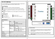
9.1 Pin Assignment.................................................................... 105<br />
<strong>Chapter</strong> 10 Mobile Phone Connection...................... 106<br />
10.1 PDA...................................................................................... 107<br />
10.1.1 Installing GView V2......................................................107<br />
10.1.2 Activating the GView Function .....................................108<br />
10.1.3 Connecting to the IP Camera.......................................108<br />
10.1.4 Playing Back the Recordings from the IP Camera.......109<br />
10.1.5 Other Functions ...........................................................110<br />
10.2 Windows Smartphone.......................................................... 116<br />
10.2.1 Installing MSView V2 / V3............................................116<br />
10.2.2 Activating the MSView V2 / V3 Function......................116<br />
10.2.3 Connecting to the IP Camera.......................................117<br />
10.2.4 Playing Back the Recordings from the IP Camera.......119<br />
10.2.5 Other Functions ...........................................................120<br />
IV
10.3 Symbian Smartphone .......................................................... 121<br />
10.3.1 Installing SSView V3....................................................121<br />
10.3.2 Activating the SSView V3 Function..............................122<br />
10.3.3 Connecting to the IP Camera.......................................122<br />
10.3.4 Quick Connection ........................................................123<br />
10.3.5 Playing Back the Recordings from the IP Camera.......123<br />
10.3.6 Other Functions ...........................................................124<br />
10.4 3G Mobile Phone ................................................................. 125<br />
10.4.1 Activating the 3G Mobile Phone Function....................125<br />
10.4.2 Connecting to the IP Camera.......................................125<br />
Specifications................................................................ 127<br />
A. GV-IPCAM H.264 .................................................................... 127<br />
B. Supplied Fixed Focal Lens ...................................................... 130<br />
C. Optional DC Iris Lens .............................................................. 130<br />
Appendix….. .................................................................. 131<br />
V
1<br />
Introduction<br />
Note for Recording<br />
<strong>The</strong> GV-IPCAM H.264 is designed to work with GV-System/GV-NVR, a<br />
hybrid or digital video management system. Normally, the images are<br />
recorded to the memory card inserted in the camera. Once the camera is<br />
connected to GV-System/GV-NVR for video management or its Live View<br />
(Figure 3-3) is accessed through the browser, the recording to the memory<br />
card will be stopped and the recording will be taken control by GV-<br />
System/GV-NVR. When the connection between the camera and GV-<br />
System/GV-NVR is interrupted, the recording to the memory card will be<br />
resumed to back up the images on the camera.<br />
1
<strong>Chapter</strong> 1 Introduction<br />
1.1 Key Features<br />
• 1.3 Micron Progressive Scan CMOS<br />
• Built-in Web server for monitoring through IE browser<br />
• Dual video streams from two of H.264, MJPEG and MPEG4<br />
• Up to 15 frames per second in megapixel resolution (1280 x 1024)<br />
• Built-in microphone<br />
• 2-way audio communication<br />
• One sensor input and one alarm output<br />
• TV-out support<br />
• Motion detection triggering actions like image upload and output<br />
trigger<br />
• Privacy mask allowing the concealment of parts of the image that<br />
should not be viewable<br />
• IP address filtering<br />
• 3GPP/ISMA<br />
• PoE (Power over Ethernet)<br />
• Day/Night function<br />
• Megapixel and IR lens included<br />
2
1<br />
Introduction<br />
1.2 Models<br />
<strong>The</strong> GV-IPCAM H.264 has the following models. <strong>The</strong>se models can be<br />
divided into two categories: Wired models (GV-BX110D / GV-BX010D)<br />
and Wireless models (GV-BX010DW / GV-BX110DW).<br />
GV-BX110D<br />
GV-BX110DW<br />
GV-BX010D<br />
GV-BX010DW<br />
GV-IPCAM, 1.3 M, H.264, D/N<br />
GV-IPCAM, 1.3 M, H.264, D/N, Wireless<br />
GV-IPCAM, VGA, H.264, D/N<br />
GV-IPCAM, VGA, H.264, D/N, Wireless<br />
SD Card Slot: Each model also comes with the option of a mini or micro<br />
SD card slot. <strong>The</strong> SD card slot only supports the mini or micro SD/SDHC<br />
card of Class 6 or above which transfers data at 6 MB or above per<br />
second.<br />
For Supported Lenses, see Appendix.<br />
1.3 Packing List<br />
<strong>The</strong> GV-IPCAM H.264 package includes the following items:<br />
• GV-IPCAM H.264<br />
• 5-Pin <strong>Terminal</strong> <strong>Block</strong><br />
• Fixed Focal Lens (Megapixel, IR, CS Lens)<br />
• C Mount Lens Adaptor<br />
• Security Torx<br />
• Power Adaptor<br />
• Antenna (Only for Wireless models)<br />
• GV-IPCAM H.264 User’s Manual<br />
• GV-IPCAM H.264 Software CD<br />
3
1.4 System Requirement<br />
To perform the GV-IPCAM H.264 operations via web browser, ensure your<br />
PC is in good network connection, and meet this system requirement:<br />
• Microsoft Internet Explorer 6.x or later<br />
1.5 Options<br />
Optional devices can expand your GV-IPCAM H.264’s capabilities and<br />
versatility. Contact your dealer for more information.<br />
DC Iris Lens<br />
See DC Iris Lens Specifications later in this manual.<br />
GV-IR Lamp<br />
An infrared illuminator.<br />
4
1<br />
Introduction<br />
1.6 Overview<br />
1.6.1 Wired Model<br />
1 2<br />
4<br />
9<br />
7<br />
10<br />
3<br />
8<br />
5 6<br />
11<br />
Figure 1-1<br />
No. Name Description<br />
1 Audio Out Connects a speaker for audio output.<br />
2 Audio In Connects a microphone for audio input.<br />
3 I/O <strong>Terminal</strong> <strong>Block</strong><br />
For details, see <strong>Chapter</strong> 9 <strong>The</strong> I/O<br />
<strong>Terminal</strong> <strong>Block</strong>.<br />
4 Default<br />
Resets all configurations of the GV-IPCAM<br />
H.264 to the default factory settings. See<br />
6.3 Restoring to Factory Default Settings.<br />
5 SD Card Slot<br />
Inserts a mini or micro SD/SDHC memory<br />
card to store recording data. <strong>The</strong> figure<br />
shown here is an example of a miniSD<br />
Card slot.<br />
6 LAN / PoE Connects to a 10/100 Ethernet or PoE.<br />
7 Video Out<br />
Connects to a portable monitor for setting<br />
the focus and angle of GV-IPCAM H.264<br />
during initial installation.<br />
8 DC 12V Connector Connects to power.<br />
5
9 Status LED See 1.6.3 Status LED.<br />
10 Microphone Records the sounds.<br />
11 Auto Iris Connector<br />
If the auto iris lens is in use, plug the iris<br />
control cable to the connector.<br />
1.6.2 Wireless Model<br />
1 2 4 5<br />
10<br />
8<br />
11<br />
3<br />
9<br />
6 7<br />
12<br />
Figure 1-2<br />
No. Name Description<br />
1 Audio Out Connects a speaker for audio output.<br />
2 Audio In Connects a microphone for audio input.<br />
3 I/O <strong>Terminal</strong> <strong>Block</strong><br />
For details, see <strong>Chapter</strong> 9 <strong>The</strong> I/O<br />
<strong>Terminal</strong> <strong>Block</strong>.<br />
4 Antenna<br />
Plugs the antenna for the Wireless WLAN<br />
function<br />
5 Default<br />
Resets all configurations of the GV-<br />
IPCAM H.264 to the default factory<br />
settings. See 6.3 Restoring to Factory<br />
Default Settings.<br />
6
1<br />
Introduction<br />
6 SD Card Slot<br />
Inserts a mini or micro SD/SDHC memory<br />
card to store recording data. <strong>The</strong> figure<br />
shown here is an example of a miniSD<br />
Card slot.<br />
7 LAN / PoE Connects to a 10/100 Ethernet or PoE.<br />
8 Video Out<br />
Connects to a portable monitor for setting<br />
the focus and angle of GV-IPCAM H.264<br />
during initial installation.<br />
9 DC 12V Connector Connects to power.<br />
10 Status LED See 1.6.3 Status LED.<br />
11 Microphone Records the sounds.<br />
12 Auto Iris Connector<br />
If the auto iris lens is in use, plug the iris<br />
control cable to the connector.<br />
1.6.3 Status LED<br />
<strong>The</strong> status LED is used to reflect the system status of the camera.<br />
Status LED<br />
Red Light ON<br />
Flashing Red and<br />
Orange Lights<br />
Green Light ON<br />
Description<br />
<strong>The</strong> system powers on and succeeds to boot up.<br />
<strong>The</strong> camera is ready for use with network<br />
connectivity.<br />
Error occurs on the system.<br />
7
1.7 Focus Adjustment<br />
To adjust the focus or image clarity during the initial installation of the GV-<br />
IPCAM H.264, it is suggested to print out the diagram of radiating lines<br />
included on Software CD and hang up the diagram at the surveillance area<br />
for focus adjustment.<br />
In the following examples, the left diagram has a good focus with clear<br />
radiating lines; the right diagram has a poor focus with blurred lines.<br />
Good focus<br />
Poor focus<br />
8
1<br />
Introduction<br />
1.8 Optional Installation<br />
1.8.1 C-Mount Lenses<br />
If you use the C-mount lens, it requires a certain distance from the<br />
camera’s imaging chip; otherwise it will not be possible to focus the lens.<br />
Mount the supplied C mount adaptor to the camera, and then attach the<br />
lens onto the C mount adaptor.<br />
C Mount Adapter<br />
Completion<br />
1.8.2 Auto Iris Lenses<br />
If you use the auto iris lens, follow the steps below to install and adjust the<br />
lens.<br />
1. Plug the iris control cable to the Auto Iris Connector on the camera<br />
(No. 11, Figure 1-1 or No. 12, Figure 1-2).<br />
2. Access the Web interface of the camera to see the live view. See 3.1<br />
Accessing Your Surveillance Images.<br />
3. Adjust the camera view based on the following notes:<br />
• Point the camera to a bright area of the surveillance scene.<br />
• Avoid objects moving in the camera view during the adjustment.<br />
• Mount the camera on a stable location.<br />
• Adjust the focus until the camera view is as clear as possible.<br />
9
4. Select Video and Motion from the Web interface, select Video<br />
Settings, select Streaming 1, set the D/N option to be Color, and set<br />
the Auto Iris option to be Disable.<br />
5. Click Apply.<br />
6. On the same Video Settings page, click Start for Auto Adjustment.<br />
7. After adjustment is complete, set the D/N option to be Auto and set<br />
the Auto Iris option be Enable.<br />
8. Click Apply.<br />
9. Re-log on to the camera.<br />
1.8.3 Infrared Illuminators<br />
If you use the infrared (IR) illuminator with I/O function, follow the steps<br />
below to install it.<br />
1. Connect the infrared illuminator to the terminal block on the camera.<br />
See <strong>Chapter</strong> 9 <strong>The</strong> I/O <strong>Terminal</strong> <strong>Block</strong>.<br />
2. Access the Web interface of the camera.<br />
3. Select Video and Motion, select Video Settings, select Streaming 1<br />
and set the IR Check Function option to be Trigger by Input.<br />
4. Click Apply.<br />
For the Trigger by Input function, see 4.1.1 Video Settings.<br />
10
<strong>Chapter</strong> 2 Getting Started<br />
This section provides basic information to get the GV-IPCAM H.264<br />
working on the network.<br />
2.1 Installing on a Network<br />
<strong>The</strong>se instructions describe the basic connections to install the GV-IPCAM<br />
H.264 on the network.<br />
1. Using a standard network cable, connect the camera to your network.<br />
2. Optionally connect a speaker and a microphone for two-way audio<br />
communication.<br />
3. Connect power using one of the methods:<br />
• Using the supplied power adaptor, connect to power.<br />
• Use the Power over Ethernet (PoE) function. <strong>The</strong> power will be<br />
provided over the network cable.<br />
4. Check if the status LED on the front of the unit is on, and then you<br />
can set the IP address for the unit.<br />
Note: See “Power over Ethernet” in Specifications later in this manual<br />
before purchasing a PoE adaptor.<br />
16
2<br />
Getting Started<br />
2.2 Assigning an IP Address<br />
Designed for use on the network, the GV-IPCAM H.264 must be assigned<br />
an IP address to make it accessible.<br />
Note: <strong>The</strong> camera has a default IP address of 192.168.0.10. <strong>The</strong><br />
computer used to set the IP address must be under the same network<br />
assigned to the unit.<br />
1. Open your web browser, and type the default IP address<br />
http://192.168.0.10.<br />
2. In both Login and Password fields, type the default value admin. Click<br />
Apply.<br />
3. In the left menu, select Network and then LAN to begin the network<br />
settings.<br />
Figure 2-1<br />
17
4. Select Static IP address. Type IP Address, Subnet Mask,<br />
Router/Gateway, Primary DNS and Secondary DNS in the Configure<br />
connection parameters section.<br />
5. Click Apply. <strong>The</strong> camera is now accessible by entering the assigned<br />
IP address on the web browser.<br />
Important:<br />
• Dynamic IP Address and PPPoE should only be enabled if you know<br />
which IP address the camera will get from the DHCP server or ISP.<br />
Otherwise you must use the Dynamic DNS service to obtain a domain<br />
name linked to the camera’s changing IP address first.<br />
For details on Dynamic IP Address and PPPoE, see 5.6.3 Advanced<br />
TCP/IP.<br />
• If Dynamic IP Address and PPPoE is enabled and you cannot access<br />
the camera, you may have to reset it to the factory default and then<br />
perform the network settings again.<br />
To restore the factory settings, see the Default button in 1.6 Overview.<br />
18
2<br />
Getting Started<br />
2.3 Configuration Basics<br />
Once the camera is properly installed, the following important features can<br />
be configured using the browser-based configuration page and are<br />
discussed in the following sections in this manual:<br />
• Date and time adjustment: see 4.7.1 Date & Time Setting.<br />
• Login and privileged passwords: see 4.7.5 User Account.<br />
• Network gateway: see 4.6 Network.<br />
• Camera image adjustment: see 3.2.2 <strong>The</strong> Control Panel of the Live<br />
View Window.<br />
• Video format, resolution and frame rate: see 4.1.1 Video Settings.<br />
19
<strong>Chapter</strong> 3 Accessing the Camera<br />
Two types of users are allowed to log on to the GV-IPCAM H.264:<br />
Administrator and Guest. <strong>The</strong> Administrator has unrestricted access to all<br />
system configurations, while the Guest has the access to live view and<br />
network status only.<br />
3.1 Accessing Your Surveillance Images<br />
Once installed, your GV-IPCAM H.264 is accessible on a network. Follow<br />
these steps to access your surveillance images:<br />
1. Start the Internet Explorer browser.<br />
2. Enter the IP address or the domain name of the camera in the<br />
Location/Address field of your browser.<br />
Figure 3-1<br />
3. Enter the login name and password.<br />
• <strong>The</strong> default login name and password for Administrator are<br />
admin.<br />
• <strong>The</strong> default login name and password for Guest are guest.<br />
20
3<br />
Accessing the Camera<br />
4. Click Apply. A video image, similar to the example on Figure 3-2, is<br />
now displayed in your browser.<br />
Note: To enable the updating of images in Internet Explorer, you must<br />
set your browser to allow ActiveX Controls and perform a once-only<br />
installation of <strong>GeoVision</strong>’s ActiveX component onto your computer.<br />
3.2 Functions Featured on the Main Page<br />
This section introduces the features of the Live View window and Network<br />
Status on the main page. <strong>The</strong> two features are accessible by both<br />
Administrator and Guest.<br />
Main Page of Guest Mode<br />
▼ Video and Motion<br />
► Live View<br />
► Streaming 1<br />
► Streaming 2<br />
▼ Network<br />
► Status<br />
Figure 3-2<br />
<strong>The</strong> GV-IPCAM H.264 can process one video stream in two different codec<br />
and image settings. When you access the live view, click Streaming 1 or<br />
Streaming 2 in the left menu.<br />
21
3.2.1 <strong>The</strong> Live View Window<br />
9<br />
8<br />
1 2 3 4 5 6 7<br />
Figure 3-3<br />
No. Name<br />
Function<br />
1 Play Plays live video.<br />
2 Stop Stops playing video.<br />
3 Microphone<br />
Talks to the surveillance area from the local<br />
computer.<br />
4 Speaker Listens to the audio around the camera.<br />
5 Snapshot<br />
Takes a snapshot of live video.<br />
--- See 3.2.3 Snapshot of Live Video.<br />
6 File Save<br />
Records live video to the local computer.<br />
--- See 3.2.4 Video Recording.<br />
22
3<br />
Accessing the Camera<br />
7 Full Screen<br />
8 I/O Control<br />
Show System<br />
9<br />
Menu<br />
Switches to full screen view. Right-click the<br />
image to have these options: Snapshot, PIP,<br />
PAP, Resolution and Google Maps.<br />
--- See 3.2.5 Picture-in-Picture and Picture-and-<br />
Picture View for PIP and PAP views,<br />
4.7.2 GPS Maps Settings.<br />
Starts the I/O Control Panel or the Visual<br />
Automation.<br />
--- See 3.2.11 I/O Control.<br />
Brings up these functions: Alarm Notify, Video<br />
and Audio Configuration, Remote Config,<br />
Show Camera Name and Image Enhance.<br />
--- See 3.2.6 Alarm Notification,<br />
3.2.7 Video and Audio Configuration,<br />
3.2.8 Remote Configuration,<br />
3.2.9 Camera Name Display, and<br />
3.2.10. Image Enhancement.<br />
23
3.2.2 <strong>The</strong> Control Panel of the Live View Window<br />
To open the control panel of the Live View window, click the arrow button<br />
on top of the window. You can access the following functions by using the<br />
right and left arrow buttons on the control panel.<br />
Figure 3-4<br />
[Information] Displays the version of the camera, local time of the local<br />
computer, host time of the camera and the number of users logging in the<br />
camera.<br />
[Video] Displays the current video codec, resolution and data rate.<br />
[Audio] Displays the audio data rates when the microphone and speaker<br />
devices are enabled.<br />
[I/O Control] Provides a real-time graphic display of the input and output<br />
status. You can force the output to be triggered by double-clicking its icon.<br />
24
3<br />
Accessing the Camera<br />
[Alarm Notify] Displays the captured images by sensor triggers and<br />
motion detection. For this function to work, you have to configure the Alarm<br />
Notify settings first. See 3.2.6 Alarm Notification.<br />
[GPS] For details 4.7.2 GPS Map Settings.<br />
[Download] Allows you to install the programs from the hard drive.<br />
[Camera Adjustment] Allows you to adjust the image quality settings.<br />
Figure 3-5<br />
25
• Brightness: Adjusts the brightness of the image.<br />
• Contrast: Adjusts the relative differences between one pixel and the<br />
next.<br />
• Saturation: Adjusts the saturation of the image.<br />
• Sharpness: Adjusts the sharpness of the image<br />
• Gamma: Adjusts the relative proportions of bright and dark areas<br />
• White balance: <strong>The</strong> camera automatically adjusts the color to be<br />
closest to the image you are viewing. You can choose one of the three<br />
presets: Indoor, Tungsten Lamp and Outdoor. You can also choose<br />
Manual to adjust the white balance manually.<br />
• Flicker less: <strong>The</strong> camera automatically matches the frequency of your<br />
camera’s imager to the frequency of indoor light sources, e.g.<br />
fluorescent lighting. You can also select 50 Hz or 60 Hz manually. If<br />
these don’t match, faint light and dark bars may appear in your images.<br />
Check the power utility to determine which frequency is used.<br />
• Image Orientation: Changes the image orientation on the Live View<br />
window.<br />
• Shutter Speed: Determines how long the image sensor is exposed to<br />
light. <strong>The</strong> range of shutter speed is from 1/5 to 1/4000 sec. In low light<br />
conditions, fast shutter speed will lower color quality and image clarity.<br />
In such conditions, you can choose one of these presets: Auto (Low<br />
Light, Balanced) to find a balance between shutter speed and image<br />
quality, Auto (Low Light, Speed) to have smooth images at the cost of<br />
image quality, or Auto (Low Light, Quality) to get the image in best<br />
quality possible but no smoothness .<br />
Shutter Speed Balanced Quality<br />
Image Brightness Poor Good Excellent<br />
Image Clarity Poor Good Excellent<br />
Image Smoothness Excellent Good Poor<br />
26
3<br />
Accessing the Camera<br />
3.2.3 Snapshot of Live Video<br />
To take a snapshot of live video, follow these steps:<br />
1. Click the Snapshot button (No. 5, Figure 3-3). <strong>The</strong> Save As dialog<br />
box appears.<br />
2. Specify Save in, type the File name, and select JPEG or BMP as<br />
Save as Type. You may also choose whether to display the name<br />
and date stamps on the image.<br />
3. Click the Save button to save the image in the local computer.<br />
3.2.4 Video Recording<br />
You can record live video for a certain period of time to your local computer.<br />
1. Click the File Save button (No. 6, Figure 3-3). <strong>The</strong> Save As dialog<br />
box appears.<br />
2. Specify Save in, type the File name, and move the Time Period<br />
slider to specify the time length of the video clip from 1 to 5 minutes.<br />
3. Click the Save button to start recording.<br />
4. To stop recording, click the Stop button (No. 2, Figure 3-3).<br />
27
3.2.5 Picture-in-Picture and Picture-and-Picture View<br />
<strong>The</strong> full screen mode provides two types of close-up views: Picture-in-<br />
Picture (PIP) and Picture-and Picture (PAP). <strong>The</strong> two views are useful to<br />
provide clear and detailed images of the surveillance area.<br />
To access this feature:<br />
• Click the Full Screen button (No. 7, Figure 3-3). Right-click the full<br />
screen to have the options of PIP and PAP.<br />
• Right-click the live view to have the options of PIP and PAP.<br />
28
3<br />
Accessing the Camera<br />
Picture-in-Picture View<br />
With the Picture in Picture (PIP) view, you can crop the video to get a<br />
close-up view or zoom in on the video.<br />
Navigation box<br />
Inset window<br />
Figure 3-6<br />
1. Select PIP. An inset window appears.<br />
2. Click the insert window. A navigation box appears.<br />
3. Move the navigation box around in the inset window to have a closeup<br />
view of the selected area.<br />
4. To adjust the navigation box size, move the cursor to any of the box<br />
corners, and enlarge or diminish the box.<br />
5. To exit the PIP view, right-click the image and click PIP again.<br />
29
Picture-and-Picture View<br />
With the Picture and Picture (PAP) view, you can create a split video effect<br />
with multiple close-up views on the image. A total of 7 close-up views can<br />
be defined.<br />
Figure 3-7<br />
1. Select PAP. A row of three inset windows appears at the bottom.<br />
2. Draw a navigation box on the image, and this selected area is<br />
immediately reflected in one inset window. Up to seven navigation<br />
boxes can be drawn on the image.<br />
3. To adjust a navigation box size, move the cursor to any of the box<br />
corners, and enlarge or diminish the box.<br />
4. To move a navigation box to another area on the image, drag it to that<br />
area.<br />
30
3<br />
Accessing the Camera<br />
5. To change the frame color of the navigation box or hide the box, rightclick<br />
the image, select Mega Pixel Setting and click one of these<br />
options:<br />
• Display Focus Area of PAP Mode: Displays or hides the<br />
navigation boxes on the image<br />
• Set Color of Focus Area: Changes the color of the box frames.<br />
6. To delete a navigation box, right-click the desired box, select Focus<br />
Area of PAP Mode and click Delete.<br />
7. To exit the PAP view, right-click the image and click PAP again.<br />
3.2.6 Alarm Notification<br />
After input triggers and motion detection, you can be alerted by a pop-up<br />
live video and view up to four captured images.<br />
Pop-up live<br />
video<br />
Captured<br />
images video<br />
Figure 3-8<br />
31
To configure this function, click the Show System Menu button (No. 9,<br />
Figure 3-3), and select Alarm Notify. This dialog box appears.<br />
Figure 3-9<br />
• Motion Notify: Once motion is detected, the captured images are<br />
displayed on the control panel of the Live View window.<br />
• I/O Alarm Notify: Once the input device is triggered, the captured<br />
images are displayed on the control panel of the Live View window.<br />
For this function to work, the Administrator needs to install the input<br />
device properly. See 4.2.1 Input Setting.<br />
• Alert Sound: Activates the computer alarm on motion and inputtriggered<br />
detection.<br />
• IE Window Pops up: <strong>The</strong> minimized Live View window pops up on<br />
motion and input-triggered detection.<br />
• Auto Snapshot: <strong>The</strong> snapshot of live video is taken every 5 seconds<br />
on motion and input-triggered detection.<br />
• File Path: Assigns a file path to save the snapshots.<br />
32
3<br />
Accessing the Camera<br />
3.2.7 Video and Audio Configuration<br />
You can enable the microphone and speaker for two-way audio<br />
communication and adjust the audio volume. To change audio<br />
configuration, click the Show System Menu button (No. 9, Figure 3-3), and<br />
select Video and Audio Configuration.<br />
Figure 3-10<br />
3.2.8 Remote Configuration<br />
You can view the connection status of the central monitoring stations and<br />
upgrade firmware over the Internet. Click the Show System Menu button<br />
(No. 9, Figure 3-3), and select Remote Config. <strong>The</strong> Remote Config dialog<br />
box will appear.<br />
[Status] In this tab, you can see the current status of the connection to<br />
Center V2 and VSM.<br />
[Firmware Upgrade] In this tab, you can upgrade the firmware over the<br />
Internet. For details, see <strong>Chapter</strong> 5 Advanced Applications.<br />
33
3.2.9 Camera Name Display<br />
To display the streaming name on the image, click the Show System<br />
Menu button (No. 9, Figure 3-3), and select Show Camera Name.<br />
3.2.10 Image Enhancement<br />
To enhance the image quality of live video, click the Show System Menu<br />
button (No. 9, Figure 3-3), and select Image Enhance. This dialog box<br />
appears.<br />
Figure 3-11<br />
• De-Interlace: Coverts the interlaced video into non-interlaced video.<br />
• De-<strong>Block</strong>: Removes the block-like artifacts from low-quality and<br />
highly compressed video.<br />
• Enable DirectDraw: Activates the DirectDraw function.<br />
34
3<br />
Accessing the Camera<br />
3.2.11 I/O Control<br />
<strong>The</strong> I/O Control window provides a real-time graphic display of camera<br />
status, I/O status, and alarm events. Additionally, you can remotely force<br />
output to be triggered.<br />
Figure 3-12<br />
• To display the I/O control window, click the I/O Control button (No. 8,<br />
Figure 3-3).<br />
• <strong>The</strong> Alarm List is displayed in three levels. <strong>The</strong> first level indicates date,<br />
the second indicates time, and the third indicates alarm ID. Clicking the<br />
Reset button will clear the list.<br />
• To trigger an output device, highlight an output and then click the<br />
Output button.<br />
35
3.2.12 Visual Automation<br />
<strong>The</strong> Visual Automation allows you to change the current state of the<br />
electronic device by simply clicking on its image, e.g. turning the light ON.<br />
This feature is only available when the Visual Automation is set ahead by<br />
the Administrator. For details, see 4.1.4 Visual Automation.<br />
Figure 3-13<br />
• To access this feature, click the I/O Control button (No. 9, Figure 3-3)<br />
and select Visual Automation.<br />
• To change the style of the set areas, click the green I/O button on the<br />
top left corner. You will have these options:<br />
• Show All: Displays all set areas.<br />
• Rect Float: Embosses all set areas.<br />
• Set Color: Changes the frame color of all set areas<br />
36
3<br />
Accessing the Camera<br />
3.2.13 Network Status<br />
To view the network status, in the left menu, click Network and select<br />
Status.<br />
Figure 3-14<br />
37
4<br />
Administrator Mode<br />
<strong>Chapter</strong> 4 Administrator Mode<br />
<strong>The</strong> Administrator can access the system configuration through the<br />
network. Eight categories of configurations are involved in the system<br />
configuration: Video and Motion, I/O Control, Events and Alerts,<br />
Monitoring, Recording Schedule, Remote ViewLog, Network and<br />
Management.<br />
▼ Video and Motion<br />
► Live View<br />
► Video Settings<br />
► Motion Detection<br />
► Privacy Mask<br />
► Tampering Alarm<br />
► Visual Automation<br />
▼ I/O Control<br />
► Input Setting<br />
► Output Setting<br />
▼ Events and Alerts<br />
► Email<br />
► FTP<br />
► Center V2<br />
► VSM<br />
► ViewLog<br />
► 3GPP<br />
▼ Monitoring<br />
▼ Recording Schedule<br />
►Camera<br />
►I/O Monitor<br />
▼Remote ViewLog<br />
▼ Network<br />
► Status<br />
► LAN<br />
► Wireless<br />
► Advanced TCP/IP<br />
► IP Filtering<br />
▼ Management<br />
► Date and Time<br />
► GPS Map Settings<br />
► Storage Settings<br />
► User Account<br />
► Log Information<br />
► Tools<br />
Figure 4-1<br />
31
4.1 Video and Motion<br />
<strong>The</strong> GV-IPCAM H.264 can process one video stream in two different codec<br />
and image settings. Two setting pages Streaming 1 and Streaming 2 are<br />
provided for separate setup.<br />
This section includes the video image settings and how the images can be<br />
managed by using Motion Detection, Privacy Mask, Tampering Alarm and<br />
Visual Automation.<br />
32
4<br />
Administrator Mode<br />
4.1.1 Video Settings<br />
Figure 4-2<br />
33
[Name] Rename the video stream. To display the name of video stream on<br />
the Live View window, see 3.2.9 Camera Name Display.<br />
[Connection Template] Select the type of your network connection.<br />
Unless you select Customized, this option will automatically bring up the<br />
recommended video resolution, frame rate, bandwidth and GOP size.<br />
[Video Signal Type] <strong>The</strong> GV-IPCAM H.264 provides three codec options:<br />
MPEG4, H.264 and MJPEG. And there are several options for selecting<br />
image resolutions: 1280 x 1024, 640 x 480, 360 x 240 and 176 x 144. <strong>The</strong><br />
frame rate to transmit images can reach 30 fps for all kinds of resolutions,<br />
except the resolution of 1280 x 1024.<br />
Most 3GPP mobile phone supports video streaming with MPEG4 video.<br />
Due to the limitation of the bandwidth for 3GPP, only 176 x 144 and 360 x<br />
240 video resolutions will be supported for mobile phone setting. To<br />
change 3GPP port settings, see 4.3.5 3GPP.<br />
[Bandwidth Management] When using H.264 or MPEG4 it is possible to<br />
control the bitrate, which in turn allows the amount of bandwidth usage to<br />
be controlled.<br />
• VBR (Variable Bitrate): <strong>The</strong> quality of the video stream is kept as<br />
constant as possible at the cost of a varying bitrate. <strong>The</strong> bandwidth is<br />
much more efficiently used than a comparable CBR.<br />
Set the image quality to one of the 3 standards: Fair, Good, and<br />
Excellent.<br />
• CBR (Constant Bitrate): CBR is used to achieve a specific bitrate by<br />
varying the quality of the H.264 or MPEG4 stream. Select one of the<br />
bitrates from the drop-down list.<br />
[GOP Structure and Length] Set the maximum number of frames in a<br />
GOP structure (the GOP size limit).<br />
34
4<br />
Administrator Mode<br />
[Alarm Settings] <strong>The</strong> alarm settings allow you to capture images before<br />
and/or after the motion or I/O events happen.<br />
• Pre-alarm recording time: Activates video recording before an event<br />
occurs. Set the recording time to 1 or 2 seconds. <strong>The</strong> recording is<br />
saved in the butter of the camera.<br />
• Post-alarm recording time: Activates video recording onto the<br />
inserted memory card after an event occurs. Set the recording time<br />
from 1 to 30 seconds.<br />
• Split-interval: Sets the time length between each event file from 1 to<br />
5 minutes.<br />
• Record audio: Activates audio recording when an event occurs.<br />
• Overlaid with camera name: Includes streaming names on live and<br />
recorded videos.<br />
• Overlaid with date stamps: Includes date stamps on live and<br />
recorded videos.<br />
• Overlaid with time stamps: Includes time stamps on live and<br />
recorded videos.<br />
• Overlaid with digital input description: Includes the name of the<br />
selected input on live and recorded videos.<br />
[Audio In Source]<br />
• Built-in Microphone: Enable the built-in microphone to record<br />
sounds.<br />
• External Microphone: Enable the externally connected microphone<br />
to record sounds.<br />
[TVOut] Select the signal format of the Video Output (No. 7, Figure 1-1, No.<br />
8, Figure 1-2) on the camera in either NTSC or PAL.<br />
35
[Mechanical Iris Adjustment]<br />
• Auto adjustment: <strong>The</strong> option is designed for auto iris lens (DC drive).<br />
Click Start to automatically adjust the auto iris lens and bring<br />
exposure to optimum. For the user of auto iris lens, you must enable<br />
this option to make adjustment for the lens and re-log on to the<br />
camera for the first time.<br />
[Special View Setting]<br />
• D/N: Select Auto that will let the camera switch automatically to<br />
monochrome images in a poorly-lit scene. You can also switch either<br />
Black and White or Color images manually.<br />
• IR Check Function: <strong>The</strong> option is designed to determine if the<br />
surveillance area is illuminated by the infrared light (from an infrared<br />
illuminator) or by sunlight. By the checking mechanism, the built-in IR<br />
cut filter can then work correctly with the D/N function. At night, the IR<br />
cut filter turns on to filter the infrared light and the image is switched to<br />
monochrome to produce better images. At day time, the IR cut filter<br />
turns off and the image is switched to color.<br />
Indoor: <strong>The</strong> default setting. <strong>The</strong> IR Check Function is enabled in<br />
this setting.<br />
Outdoor: <strong>The</strong> IR Check Function is disabled. It is suggested to<br />
enable this option when the color temperature of outdoor lighting is<br />
6000 K or above.<br />
Triggered by Input: <strong>The</strong> D/N and IR Check functions are<br />
controlled by an input device connected to the camera, such as an<br />
infrared illuminator or timer.<br />
Note: If an infrared illuminator is installed for outdoor surveillance, it is<br />
suggested to use the Triggered by Input function to avoid the wrong<br />
judgment of lighting and the incorrect action of the IR cut filter. See 1.7.3<br />
Infrared Illuminators.<br />
• Auto Iris: <strong>The</strong> option is designed for auto iris lens (DC drive). Enable<br />
or disable the auto iris function.<br />
36
4<br />
Administrator Mode<br />
4.1.2 Motion Detection<br />
Motion detection is used to generate an alarm whenever movement occurs<br />
in the video image. You can configure up to 8 areas with different<br />
sensitivity values for motion detection.<br />
Figure 4-3<br />
1. <strong>The</strong> default sensitivity value for the whole area is 2. To define a<br />
different sensitivity value, click Reset.<br />
2. Select the desired sensitivity by moving the slider. <strong>The</strong>re are three<br />
values. <strong>The</strong> higher the value, the more sensitive the camera is to<br />
motion.<br />
3. Drag an area on the image. Click Add when you are prompted to<br />
confirm the setting.<br />
4. To create several areas with different sensitivity values, repeat Steps<br />
2 and 3.<br />
5. Click Save to save the above settings.<br />
6. If you want to trigger the alarm output when motion is detected, select<br />
Output 1 and click the Apply button. To activate the output settings,<br />
you must also start Input monitoring manually or by schedule. For<br />
related settings, see 4.4 Monitoring.<br />
37
4.1.3 Privacy Mask<br />
<strong>The</strong> Privacy Mask can block out sensitive areas from view, covering the<br />
areas with dark boxes in both live view and recorded clips. This feature is<br />
ideal for locations with displays, keyboard sequences (e.g. passwords),<br />
and for anywhere else you don’t want sensitive information visible.<br />
Figure 4-4<br />
1. Select the Enable option.<br />
2. Drag the area(s) where you want to block out on the image. Click Add<br />
when you are prompted to confirm the setting.<br />
3. Click the Save button to save all the settings.<br />
38
4<br />
Administrator Mode<br />
4.1.4 Tampering Alarm<br />
<strong>The</strong> Tampering Alarm is used to detect when a camera is being physically<br />
tampered. An alarm can be generated when the camera is moved, covered<br />
up, or out of focus. <strong>The</strong> alarm approaches include the triggered output<br />
device and e-mail alert. To have the tampering alarm, first set up these<br />
alarm approaches properly:<br />
• To trigger the output device when a tampering event occurs, enable<br />
the output setting and select Tampering Alarm. See 4.2.2 Output<br />
Settings.<br />
• To trigger the e-mail alert when a tampering event occurs, enable the<br />
e-mail setting and select Tampering Alarm. See 4.3.1 E-Mail.<br />
Figure 4-5<br />
39
To configure the tampering alarm:<br />
1. Select the Enable option.<br />
2. If you want the camera to ignore any movement or scene change in<br />
certain areas, click the button to drag areas on the camera view.<br />
3. Select the desired detection sensitivity by moving the slider. <strong>The</strong><br />
higher the value, the more sensitive the camera is to scene changes.<br />
4. In the Tolerance Time of Alarm field, specify the time length allowed<br />
for scene changes before an alarm is generated.<br />
5. In the Duration of Alarm field, specify the duration of the alarm after<br />
which the triggered output device will be turned off.<br />
6. To trigger an alarm when the scene turns dark, e.g. the lens<br />
of camera has been covered, select Alarm for Dark Images.<br />
7. Click Apply to save all the settings.<br />
8. Start monitoring to enable the function. To have output alarm, it is<br />
required to start Input monitoring. See 4.4 Monitoring.<br />
When the camera has been tampered, the output device can be activated.<br />
To turn off the output device immediately, return to this setting page, and<br />
click Restart Detection.<br />
40
4<br />
Administrator Mode<br />
4.1.5 Visual Automation<br />
This intuitive feature helps you automate any electronic device by<br />
triggering the connected output device. When you click on the image of the<br />
electronic device, you can simply change its current state, e.g. light ON.<br />
Figure 4-6<br />
1. Select the Enable option.<br />
2. Drag an area on the image of the electronic device. This dialog box<br />
appears.<br />
Figure 4-7<br />
3. Assign the connected module and output device. In the Note field,<br />
type a note to help you manage the device. Click OK to save the<br />
settings.<br />
4. To change the frame color of the set area, click the Set Color button.<br />
5. To emboss the set area, select Float Up; or keep it flat by selecting<br />
Normal.<br />
6. Click the Save Set button to apply the settings.<br />
7. To perform the function, see 3.2.12 Visual Automation.<br />
41
4.2 Digital I/O Settings<br />
<strong>The</strong> I/O terminal block, on the rear of the camera, provides the interface for<br />
one external alarm and sensor device. For details on the I/O terminal block,<br />
see <strong>Chapter</strong> 9 I/O <strong>Terminal</strong> <strong>Block</strong>.<br />
4.2.1 Input Settings<br />
To activate the sensor input, select Enable.<br />
Figure 4-8<br />
• Normal State: You can set the input state to trigger actions by<br />
selecting Open Circuit (N/O) or Grounded Circuit (N/C).<br />
• Latch Mode: Enable this option to have a momentary output alarm.<br />
• Trigger digital output relay: When this option is enabled, the output<br />
will be triggered once the input is activated.<br />
• Record: Enable this option to start recording when the input is<br />
triggered.<br />
• Send Video to Center V2: Enable this option to send the images to<br />
Center V2 when the input is triggered.<br />
Note: <strong>The</strong> functions of triggering the output, the recording and sending<br />
video to Center V2 only work after you start Input monitoring manually<br />
or by schedule. To configure the input monitoring, see 4.4 Monitoring.<br />
42
4<br />
Administrator Mode<br />
4.2.2 Output Settings<br />
Select Enable to start the output device. Choose the output signal that<br />
mostly suits the device you are using: N/O (Open Circuit), N/C (Grounded<br />
Circuit), N/O Toggle, N/C Toggle, N/O Pulse or N/C Pulse. For Toggle<br />
output type, the output continues to be triggered until a new input trigger<br />
ends the output. For Pulse output type, the output is triggered for the<br />
amount of time you specify in the Trigger Pulse Mode for x Seconds field.<br />
[Alarm Settings] You can choose to automatically trigger the digital output<br />
under these conditions: tampering alarm, disk write error (Rec Error) and<br />
hard disk full (HD Full).<br />
Figure 4-9<br />
43
4.3 Events and Alerts<br />
For the events of motion detection or I/O trigger, the Administrator can set<br />
up the two trigger actions:<br />
1. Send a captured still image by E-mail or FTP.<br />
2. Notify Center Monitoring Station, Center V2 or VSM, by video or text<br />
alerts.<br />
To have above trigger actions, you must set the following functions in<br />
advance:<br />
• Motion Detection (See 4.1.2 Motion Detection)---Optional<br />
• Input Setting (See 4.2.1 Input Setting)<br />
• For e-mail and FTP alerts, it is required to start monitoring (See 4.4<br />
Monitoring).<br />
Note: <strong>The</strong> Motion Detection function is an optional setting since it is<br />
activated by default.<br />
44
4<br />
Administrator Mode<br />
4.3.1 E-mail<br />
After a trigger event, the camera can send the e-mail to a remote user<br />
containing a captured still image.<br />
Figure 4-10<br />
[Enable] Select to enable the e-mail function.<br />
• Sever URL/IP Address: Type the URL address or IP address of the<br />
SMTP Server.<br />
• Server Port: Modify the port number of the SMTP Server. Or keep<br />
the default value 25.<br />
• From email address: Type the sender’s e-mail address.<br />
• Send to: Type the e-mail address(s) you want to send alerts to.<br />
• Alerts Interval Time: Specify the interval between e-mail alerts. <strong>The</strong><br />
interval is between 0 and 60 minutes. <strong>The</strong> option is useful for the<br />
frequent event occurrence, by which any event triggers during the<br />
interval period will be ignored.<br />
45
[Need authentication to login] If the SMTP Server needs authentication,<br />
enable this option and type a valid username and password to log in the<br />
SMTP server.<br />
[E-Mail Alarm Settings] You can choose to automatically send an e-mail<br />
alert under these conditions: tampering alarm, disk write error (Rec Error)<br />
and hard disk full (HD Full).<br />
For the related settings to send e-mail alerts, see 4.1.2 Motion Detection,<br />
4.2.1 Input Setting and 4.4 Monitoring.<br />
4.3.2 FTP<br />
You can also send the captured still image to a remote FTP server for<br />
alerts.<br />
Figure 4-11<br />
46
4<br />
Administrator Mode<br />
[Enable] Select to enable the FTP function.<br />
• Server URL/IP Address: Type the URL address or IP address of the<br />
FTP Server.<br />
• Server Port: Type the port number of the FTP Server. Or keep the<br />
default value 21.<br />
• User Name: Type a valid user name to log into the FTP Server.<br />
• Password: Type a valid password to log into the FTP Server.<br />
• Remote Directory: Type the name of the storage folder on the FTP<br />
Server.<br />
• Alerts Interval time in minute: Specify the interval between FTP<br />
alerts. <strong>The</strong> interval can be between 0 and 60 minutes. <strong>The</strong> option is<br />
useful for the frequent event occurrence by which any event triggers<br />
during the interval period will be ignored.<br />
[Alarm Settings]<br />
• Motion Detection: Once the motion is detected on the camera, a still<br />
image will be sent to the FTP Server.<br />
<br />
Continuously send images upon trigger events (motion): A<br />
sequence of snapshots is uploaded to the FTP Server when<br />
motion is detected on the camera.<br />
• Digital Input: Once the input is triggered, a still image will be sent to<br />
the FTP Server.<br />
<br />
Continuously send images upon trigger events (input): A<br />
sequence of snapshots is uploaded to the FTP Server when the<br />
input is triggered.<br />
[Act as FTP Server]<br />
• Enable FTP access to the GV-IP Cam: <strong>The</strong> camera acts as a FTP<br />
server, enabling users to download AVI files.<br />
• Use alternative port: <strong>The</strong> default port is set to 21.<br />
47
To access the internal FTP server through a web browser, enter the IP<br />
address or the domain name of the camera in your browser like this:<br />
ftp://192.168.0.10<br />
When you are prompted for Username and Password, enter the default<br />
value ftpuser in both fields. <strong>The</strong>n you should find the AVI files recorded<br />
after trigger events.<br />
To change login information of the internal FTP server, see 4.7.5 User<br />
Account. For the related settings to send FTP alerts, see 4.1.2 Motion<br />
Detection, 4.2.1 Input Settings and 4.4 Monitoring.<br />
48
4<br />
Administrator Mode<br />
4.3.3 Center V2<br />
After a motion or an I/O triggered event, the central monitoring station<br />
Center V2 can get notified by live videos and text alerts. For the live<br />
monitoring through Center V2, you must already have a subscriber account<br />
on Center V2.<br />
Figure 4-12<br />
49
To enable the Center V2 connection:<br />
1. Activate Link: Enable the monitoring through Center V2.<br />
2. Host Name or IP Address: Type the host name or IP address of<br />
Center V2.<br />
3. Port Number: Match the port to the Port 2 value on Center V2. Or<br />
keep the default value 5551.<br />
4. User Name: Type a valid user name to log into Center V2.<br />
5. Password: Type a valid password to log into Center V2.<br />
6. Click Apply. <strong>The</strong> Connection Status should display “Connected” and<br />
connected time.<br />
<strong>The</strong>se options you can also find on this Center V2 setting page:<br />
• Cease motion detection messages from: Stops notifying Center V2<br />
of motion-triggered events.<br />
• Cease input trigger messages from: Stops notifying Center V2 of<br />
input-triggered events.<br />
• Enable schedule mode: Starts the monitoring through Center V2<br />
based on the schedule you set in the Select Schedule Time section.<br />
Refer to 5.5 Schedule for the same settings.<br />
For related settings to activate the monitoring through Center V2, see 4.1.2<br />
Motion Detection, 4.2.1 Input Setting, and 7.1 Center V2.<br />
50
4<br />
Administrator Mode<br />
4.3.4 VSM<br />
After a motion or an I/O triggered event, the central monitoring station VSM<br />
can get notified by text alerts. For the monitoring through VSM, you must<br />
already have a subscriber account on VSM.<br />
Figure 4-13<br />
To enable the VSM connection:<br />
1. Activate Link: Enable the monitoring through VSM.<br />
2. Host Name or IP Address: Type the host name or IP address of<br />
VSM.<br />
3. Port Number: Match the port to the Port 2 value on VSM. Or keep<br />
the default value 5609.<br />
51
4. User Name: Type a valid user name to log into VSM.<br />
5. Password: Type a valid password to log into VSM.<br />
6. Click Apply. <strong>The</strong> Connection Status should display “Connected” and<br />
connected time.<br />
<strong>The</strong>se options you can also find on this VSM setting page:<br />
• Cease motion detection messages from: Stops notifying VSM of<br />
motion-triggered events.<br />
• Cease input trigger messages from: Stops notifying VSM of inputtriggered<br />
events.<br />
• Enable schedule mode: Starts the monitoring through VSM based<br />
on the schedule you set in the Select Schedule Time section. Refer<br />
to 5.5 Schedule for the same settings.<br />
For related settings to activate the monitoring through VSM, see 4.1.2<br />
Motion Detection and 4.2.1 Input Settings, and 7.2 VSM.<br />
52
4<br />
Administrator Mode<br />
4.3.5 ViewLog Server<br />
<strong>The</strong> ViewLog Server is designed for remote playback function. This server<br />
allows you to remotely access the recorded files saved at the GV-IPCAM<br />
H.264 and play back video with the player ViewLog.<br />
Select Enable to activate the built-in server. Keep the default port 5552 or<br />
modify it if necessary. For details on the remote playback, see 5.2.2<br />
Playback Using Remote ViewLog.<br />
Figure 4-14<br />
53
4.3.6 3GPP<br />
<strong>The</strong> 3GPP Server enables video and audio streaming to your 3G-enabled<br />
mobile phone.<br />
Figure 4-15<br />
• Activate Link: Enable the 3GPP service.<br />
• RTSP/TCP Port: Keep the default value 8554, or modify it if<br />
necessary.<br />
• RTP/UDP Port: Keep the default range from 17300 to 17319, or<br />
modify it if necessary. <strong>The</strong> number of ports for use is limited to 20.<br />
• Max Connection: Set the maximum number of connections to the<br />
GV-IPCAM H.264. <strong>The</strong> maximum value is 20.<br />
For details on remote monitoring with mobile phones, see <strong>Chapter</strong> 10<br />
Remote Monitoring with Mobile Phones.<br />
54
4<br />
Administrator Mode<br />
4.4 Monitoring<br />
You can start monitoring manually, by schedule or by input trigger.<br />
Note: See Note for Recording at the beginning of the manual.<br />
Figure 4-16<br />
[Manual] Manually activates motion detection and I/O monitoring. Select<br />
one of the following options and then click the Start button.<br />
• Select all: Manually starts both motion detection and I/O monitoring.<br />
• Camera: Manually starts recording. Select the desired recording<br />
mode for recording.<br />
• Input: Manually starts I/O monitoring. When the sensor input is<br />
triggered, its associated camera and output will be activated for<br />
recording and alerting. For this setting, see 4.2.1 Input Setting.<br />
[Schedule] <strong>The</strong> system starts motion detection and I/O monitoring<br />
according to the schedule you have set. For schedule settings, see 4.5<br />
Schedule.<br />
55
[Camera Status Icon]<br />
: On standby<br />
: Enabled for motion detection and input trigger<br />
56
4<br />
Administrator Mode<br />
4.5 Recording Schedule<br />
<strong>The</strong> schedule is provided to activate recording and I/O monitoring on a<br />
specific time each day.<br />
4.5.1 Recording Schedule Settings<br />
You can set the schedule for recording.<br />
Figure 4-17<br />
• Span 1- Span 3: Set a different recording mode for each time frame<br />
during the day. Each day can be divided into 3 time frames,<br />
represented by Span 1 to Span 3.<br />
• Weekend: Enable this option to start monitoring all day on the<br />
weekend and select the recording mode to be used. Define whether<br />
your weekend includes Saturday and Sunday or Only Sunday.<br />
• Special Day: Set the recording mode on a specified day.<br />
57
4.5.2 I/O Monitoring Settings<br />
You can set the schedule for I/O monitoring to start.<br />
Figure 4-18<br />
• Span 1- Span 3: Set different time frames during the day to enable<br />
I/O monitoring. Each day can be divided into 3 time frames,<br />
represented by Span 1 to Span 3.<br />
• Weekend: Enable this option to start I/O monitoring all day on the<br />
weekend and define whether your weekend includes Saturday and<br />
Sunday or Only Sunday.<br />
• Special Day: Enable I/O monitoring on a specified day.<br />
Note: In Recording Schedule and I/O Monitoring Schedule, if the<br />
settings for Special Day conflict with those for Span 1-3 or Weekend,<br />
the Special Day settings will get priority.<br />
58
4<br />
Administrator Mode<br />
4.6 Remote ViewLog<br />
With the Remote ViewLog function, you can play back the files recorded at<br />
the GV-IPCAM H.264 over TCP/IP network.<br />
For the first-time user, you need to install the Remote ViewLog program<br />
from the Software DVD. For remote access to the camera, the ViewLog<br />
Server built in the unit must be enabled. See 4.3.5 ViewLog Server.<br />
For details on connecting to the camera for playback , see 5.2.2 Playback<br />
Using Remote ViewLog.<br />
59
4.7 Network<br />
<strong>The</strong> Network section includes some basic but important network<br />
configurations that enable the camera to be connected to a TCP/IP<br />
network.<br />
4.7.1 LAN<br />
According to your network environment, select among Static IP, DHCP and<br />
PPPoE.<br />
Figure 4-19<br />
60
4<br />
Administrator Mode<br />
[LAN Configuration]<br />
• Dynamic IP address: <strong>The</strong> network environment has a DHCP server.<br />
This option should only be enabled if you know which IP address the<br />
camera will get from the DHCP server, or you have obtained a domain<br />
name from the DDNS service provider that always links to the<br />
camera’s changing IP address.<br />
• Static IP address: Assign a static IP or fixed IP to the camera. Type<br />
the camera’s TCP/IP and DNS parameters in the Configure<br />
connection parameters section.<br />
• PPPoE: <strong>The</strong> network environment is xDSL connection. Type the<br />
Username and Password provided by ISP to establish the connection.<br />
If you use the xDSL connection with dynamic IP addresses, first use<br />
the DDNS function to obtain a domain name linking to the camera’s<br />
changing IP address.<br />
[Configure connection parameters]<br />
Type the camera’s IP address, Subnet Mask, Router/Gateway, Primary<br />
DNS server and Secondary DNS server.<br />
Parameters<br />
Default<br />
IP address 192.168.0.10<br />
Subnet Mask 255.255.255.0<br />
Router/Gateway 192.168.0.1<br />
Primary DNS server 192.168.0.1<br />
Secondary DNS server 192.168.0.2<br />
For details on Dynamic DNS Server Settings, see 4.6.3 Advanced TCP/IP.<br />
61
4.7.2 Wireless-Client Mode<br />
<strong>The</strong> wireless function is available on the models: GV-BX010DW and GV-<br />
BX110DW.<br />
Figure 4-20<br />
• Network type: Select the network mode Ad Hoc or Infrastructure.<br />
<br />
<br />
Infrastructure: Via the Access Point to connect to the Internet.<br />
This mode further gives wireless access to the Internet or data<br />
sharing under a previously wired environment.<br />
Ad-Hoc: A Peer-to-Peer mode. This mode connects to other<br />
computer with the WLAN card, and does not need the Access<br />
Point to connect to each other.<br />
• Network name (SSID): <strong>The</strong> SSID (Service Set Identify) is a unique<br />
name that identifies a particular wireless network. Type SSID of the<br />
Wireless LAN group or Access Point you are going to connect to.<br />
<br />
Access Point Survey: Click this button to search all the available<br />
Access Points (Infrastructure mode) and wireless stations (AD-<br />
Hoc mode) within the range of your WLAN card.<br />
62
4<br />
Administrator Mode<br />
• Authentication Type: Select one of these network authentications<br />
and data encryptions: Disable, WEP, WPAPSK-TKIP, WPAPSK-<br />
AES, WPA2PSK-TKIP or WPA2PSK-AES.<br />
<br />
<br />
<br />
<br />
Disabled: No authentication is needed within the wireless<br />
network.<br />
WEP (Wired Equivalent Privacy): A type of data encryption.<br />
Type up to four WEP Keys in HEX or ASCII format. Note that if<br />
you use HEX format, only digits 0-9 and letters A-F, a-f are valid.<br />
WPAPSK-TKIP and WPA2PSK-TKIP: Type WPA-PSK (Pre-<br />
Shared Key) for data encryption.<br />
WPAPSK-AES and WPA2PSK-AES: Type WPA-PSK (Pre-<br />
Shared Key) for data encryption.<br />
Note: Your encryption settings must match those used by the Access<br />
Points or wireless stations with which you want to associate.<br />
63
4.7.3 Advanced TCP/IP<br />
This section introduces the advanced TCP/IP settings, including DDNS<br />
Server, HTTP port, streaming port and UPnP.<br />
Figure 4-21<br />
[Dynamic DNS Server Settings] DDNS (Dynamic Domain Name System)<br />
provides a convenient way of accessing the camera when using a dynamic<br />
IP. DDNS assigns a domain name to the camera, so that the Administrator<br />
does not need to go through the trouble of checking if the IP address<br />
assigned by DHCP Server or ISP (in xDSL connection) has changed.<br />
Before enabling the following DDNS function, the Administrator should<br />
have applied for a Host Name from the DDNS service provider’s website.<br />
<strong>The</strong>re are 2 providers listed in the camera: <strong>GeoVision</strong> DDNS Server and<br />
DynDNS.org.<br />
64
4<br />
Administrator Mode<br />
To enable the DDNS function:<br />
1. Enable: Enable the DDNS function.<br />
2. Service Provider: Select the DDNS service provider you have<br />
registered with.<br />
3. Host Name: Type the host name used to link to the camera. For the<br />
users of <strong>GeoVision</strong> DDNS Server, it is unnecessary to fill the field<br />
because the host name will be detected and brought up automatically.<br />
4. User Name: Type the user name used to enable the service from the<br />
DDNS.<br />
5. Password: Type the password used to enable the service from the<br />
DDNS.<br />
6. Click Apply.<br />
[HTTP Port Settings] <strong>The</strong> HTTP port enables connecting the camera to<br />
the web. For security integration, the Administrator can hide the server<br />
from the general HTTP port by changing the default HTTP port of 80 to a<br />
different port number within the range of 1024 through 65535.<br />
[GV-IP Camera Streaming Port Settings] <strong>The</strong> VSS port enables<br />
connecting the camera to the GV-System. <strong>The</strong> default setting is 10000.<br />
[UPnP Settings] UPnP (Universal Plug & Play) is a networking<br />
architecture that provides compatibility among networking equipment,<br />
software and peripherals of the 400+ vendors that are part of the Universal<br />
Plug and Play Forum. It means that they are listed in the network devices<br />
table for the operating system (such as Windows XP) supported by this<br />
function. Enabling this function, you can connect to the camera directly by<br />
clicking on the camera listed in the network devices table.<br />
65
4.7.4 IP Filter Settings<br />
<strong>The</strong> Administrator can set IP filtering to restrict access to the camera.<br />
Figure 4-22<br />
To enable the IP Filter function:<br />
1. Enable IP Filtering: Enable the IP Filter function.<br />
2. Filtered IP: Type one IP address or a range of IP addresses you want<br />
to restrict the access.<br />
3. Action to take: Select the action of Allow or Deny to be taken for<br />
the IP address(es) you have specified.<br />
4. Click Apply.<br />
66
4<br />
Administrator Mode<br />
4.8 Management<br />
<strong>The</strong> Management section includes the settings of data and time and user<br />
account. You can also view the firmware version and execute certain<br />
system operations.<br />
4.8.1 Date & Time Settings<br />
<strong>The</strong> date and time settings are used for date and time stamps on the image.<br />
Figure 4-23<br />
67
[Date & Time on GV-IP Camera] Displays the current date and time on<br />
the camera.<br />
[Time Zone] Sets the time zone for local settings. Select Enable Daylight<br />
Saving Time to automatically adjust the camera for daylight saving time.<br />
Type the Start Time and End Time to enable the daylight saving function.<br />
Also see 5.2.3 Playback of Daylight Saving Time Events.<br />
[Synchronized with a Network Time Server] By default, the camera uses<br />
the timeserver of time.windows.com to automatically update its internal<br />
clock every 24 hours. You can also change the host name or IP setting to<br />
the timeserver of interest.<br />
[Synchronized with your computer or modify manually] Manually<br />
changes the camera’s date and time. Or, synchronize the camera’s date<br />
and time with those of the local computer.<br />
[Overlaid Date and Time Settings] Select the display format of date and<br />
time stamps on the image. For this function to work, you must also enable<br />
the Overlaid with date stamps and Overlaid with time stamps options in<br />
Figure 4-2.<br />
68
4<br />
Administrator Mode<br />
4.8.2 GPS Maps Settings<br />
<strong>The</strong> Maps Settings allows you to see the location of your GV-IPCAM H.264<br />
on Google maps, without a GPS device.<br />
To see the location of your camera on maps:<br />
1. It is required to sign up for a Google Maps API key before using the<br />
Google Maps. Click Link to the Google Maps API.<br />
Figure 4-24<br />
2. Enter the registered Maps API Key, the longitude and latitude of your<br />
camera, and location name. Click Apply to enable this function.<br />
3. Open the control panel of the Live View window.<br />
Figure 4-25<br />
69
4. Click Open. A warning message appears.<br />
Figure 4-26<br />
5. Right-click the warning message and select Allow <strong>Block</strong>ed Content.<br />
<strong>The</strong> map will be displayed. <strong>The</strong> icon indicates the location of your<br />
camera. At the upper right corner you have options to view different<br />
map formats, such as Satellite and Hybrid.<br />
Figure 4-27<br />
70
4<br />
Administrator Mode<br />
4.8.3 Storage Settings<br />
Based on Linux ext3 file system, the GV-IPCAM H.264 supports external<br />
storage devices, memory cards, for video and audio recording. Before<br />
using storage devices, you need to format them by using the following<br />
Storage Settings. After being formatted, the storage devices will be ready<br />
to use by Linux OS of the camera.<br />
Figure 4-28<br />
[Storage Settings]<br />
If Enable recycling is selected, when the space of the storage device is<br />
lower than the specified space, the system will overwrite the oldest<br />
recorded files.<br />
If Enable recycling is not selected, the system will stop recording when<br />
the specified space is reached.<br />
[Keep days (1-255)] Specify the number of days to keep the files from 1<br />
day to 255 days. When both Keep days and Enable recycling are<br />
selected, the system applies whichever condition comes first. For example,<br />
if the specified smallest amount of storage space comes earlier than the<br />
designated keep days, then recycle is applied first.<br />
71
[Disk Information]<br />
This section shows the details of the attached storage device.<br />
[Partition Information]<br />
This section shows the partition details of the attached storage device.<br />
To add a memory card:<br />
1. Insert the memory card to the camera.<br />
2. Click the Format button.<br />
3. After the format is complete, the partition information will display. <strong>The</strong><br />
maximum space for one partition is 200 GB.<br />
To remove a memory card:<br />
1. Click the Remove button.<br />
2. When you are prompted to ensure the action, click Yes. <strong>The</strong> page will<br />
be refreshed and the partition information will be cleaned.<br />
3. Remove the memory card from the camera.<br />
Note:<br />
1. If Enable Recycle is selected, the available space of the storage<br />
device must be higher than the space you specified at the Stop<br />
recording or recycle disk when free space of disk is smaller<br />
than x option. Otherwise no video will be recoded.<br />
2. <strong>The</strong> recording data may be lost if you remove the USB mass storage<br />
device during recording.<br />
3. If you do not remove the storage device properly, the data cannot be<br />
read in another computer. In this case, re-plug the storage device<br />
back to the camera. <strong>The</strong> system will repair the data automatically.<br />
When the system is repairing the data, the Remove field will display<br />
“Repairing”.<br />
72
4<br />
Administrator Mode<br />
4.8.5 User Account<br />
You can change the login name and password of Administrator and Guest.<br />
<strong>The</strong> default Administrator login name and password are admin; the default<br />
Guest login name and password are guest. To allow a Guest user log in<br />
without entering name and password, select Disable authentication for<br />
guest account.<br />
Figure 4-29<br />
73
4.8.6 Log Information<br />
<strong>The</strong> log information contains dump data that is used by service personnel<br />
for analyzing problems.<br />
Figure 4-30<br />
74
4<br />
Administrator Mode<br />
4.8.7 Tools<br />
You can execute certain system operations and view the firmware version.<br />
Figure 4-31<br />
[Host Settings] Enter a descriptive name for the camera.<br />
[Firmware Update] This field displays the firmware version of the camera.<br />
[System Settings] Clicking the Load Default button will make the camera<br />
restore factory default settings.<br />
Note: After applying the default function, you need to configure the<br />
camera’s network setting again.<br />
[Reboot] Clicking the Reboot button will make the camera perform<br />
software reset.<br />
75
<strong>Chapter</strong> 5 Recording and Playback<br />
<strong>The</strong> GV-IPCAM H.264 can record video and audio directly to the memory<br />
card. You can play back the recorded files on the GV-System or over the<br />
TCP/IP network.<br />
Note: See Note for Recording at the beginning of the manual.<br />
5.1 Recording<br />
To enable the recording function:<br />
1. Insert the memory card to the camera. See “To add a memory card”,<br />
4.8.3 Storage Settings.<br />
2. If you like to set up the pre-recording, post-recording or audio<br />
recording, see 4.1.1 Video Settings.<br />
3. If you like to set up the schedule for video recording or I/O monitoring,<br />
see 4.5 Recording Schedule.<br />
4. If you like to configure the areas and sensitivity values for motion<br />
detection, see 4.1.2 Motion Detection.<br />
5. If you want the recording to be triggered by input device, configure the<br />
operation of input device. See 4.2.1 Input Settings.<br />
6. To start recording and I/O monitoring, see 4.4 Monitoring.<br />
<strong>The</strong> camera will start recording in case of motion detection, I/O trigger, or<br />
during the scheduled time.<br />
76
5<br />
Recording and Playback<br />
5.2 Playback<br />
<strong>The</strong>se methods are available to play back the video files recorded at the<br />
GV-IPCAM H.264:<br />
• Playback by using the memory card by connecting it directly to the<br />
GV-System through a memory card reader<br />
• Playback by using the Remote ViewLog function over the TCP/IP<br />
network<br />
• Playback by using the recorded files downloaded from built-in FTP<br />
Server<br />
5.2.1 Playback Using the Memory Card<br />
You can play back the files recorded at the GV-IPCAM H.264 by<br />
connecting the memory card to GV-System through a memory card reader.<br />
However, GV-System is run on Windows system while the files recorded at<br />
the GV-IPCAM H.264 is of Linux file system. To enable Windows to<br />
recognize the files, you need to install the program Ext2 Installable File<br />
System included on the Software CD.<br />
1. Insert the Software CD, select IFS Drives and follow the onscreen<br />
instructions for installation.<br />
2. Run IFS Drives from Control Panel, and assign the drive name(s) to<br />
each available partition in the storage device.<br />
Figure 5-1<br />
77
3. Run ViewLog.<br />
4. Click the Advanced button , select Reload Database and click<br />
Video Server/Compact DVR. This dialog box appears.<br />
Figure 5-2<br />
5. Click Add to assign the hard drive.<br />
6. Click OK to load the data to the ViewLog for playback.<br />
78
5<br />
Recording and Playback<br />
5.2.2 Playback over Network<br />
With the Remote ViewLog function, you can play back the files recorded at<br />
the GV-IPCAM H.264 over TCP/IP network.<br />
1. <strong>The</strong> camera needs to allow the remote access with ViewLog Server<br />
activated. See 4.3.5 ViewLog Server.<br />
2. For the first time user, run the Remote ViewLog program from the<br />
Software DVD. Next time whenever you like to use this function,<br />
access this option from the camera’s Web interface.<br />
3. When this dialog box appears, type the camera’s IP address, login ID<br />
and password. Keep the default port 5552 or modify it if necessary.<br />
Figure 5-3<br />
3. In the Host Type field, select GV-IP Device.<br />
4. Click Connect to access the files of the camera for playback.<br />
79
5.2.3 Access to the Recorded Files through FTP Server<br />
<strong>The</strong> built-in FTP Server allows you to download the recorded files saved on<br />
the memory card. You can play back the downloaded files of AVI format<br />
with any multimedia player. For details to download files, see [Act as FTP<br />
Server], 4.3.2 FTP.<br />
5.2.4 Playback of Daylight Saving Time Events<br />
On GV-System, you can retrieve the events recorded during the Daylight<br />
Saving Time (DST) period from the GV-IPCAM H.264 for playback. You<br />
can also connect the memory card to GV-System for playback.<br />
<strong>The</strong> following instructions describe how to retrieve the recorded files from<br />
the GV-IPCAM H.264 over network. If you like to use the memory card for<br />
playback, first follow the instructions in 5.2.1 Playback Using the Memory<br />
Card to load the recorded files to ViewLog, and then follow Steps 4-7<br />
below to play back DST events.<br />
1. <strong>The</strong> camera must allow the remote access with ViewLog Server<br />
activated. See 4.3.5 ViewLog Server.<br />
2. To remotely connect to the camera from GV-System, click the Tools<br />
button and select Remote ViewLog Service. <strong>The</strong> Connect to Remote<br />
ViewLog Service dialog box appears.<br />
3. Enter the connection information of the camera, and click Connect.<br />
Once the connection is established, the video events will be displayed<br />
on the Video Event list.<br />
80
5<br />
Recording and Playback<br />
4. On the Date Tree, select the date of Daylight Saving Time. A separate<br />
DST subfolder will be displayed as illustrated below.<br />
Figure 5-4<br />
5. On the Video Event list, select desired events, and click the Play<br />
button to start.<br />
Note:<br />
1. <strong>The</strong> playback function is only compatible with the GV-System of<br />
version 8.3 or later.<br />
2. <strong>The</strong> AVI file recorded during the DST period is named with the<br />
prefix “GvDST”, e.g. GvDST20081022xxxxxxxxx.avi, to<br />
differentiate from the regular AVI file named with the prefix “Event”,<br />
e.g. Event20081022xxxxxxxxx.avi.<br />
81
<strong>Chapter</strong> 6 Advanced Applications<br />
This chapter introduces more advanced applications.<br />
6.1 Upgrading System Firmware<br />
<strong>GeoVision</strong> will periodically release the updated firmware on the website.<br />
<strong>The</strong> new firmware can be simply loaded into the GV-IPCAM H.264 by<br />
using the Web interface or IP Device Utility included in the Software CD.<br />
Important Notes before You Start<br />
Before you start updating the firmware, please read these important notes:<br />
1. While the firmware is being updated,<br />
A) the power supply must not be interrupted, and<br />
B) do not unplug the Ethernet cable if the cable is the source of<br />
power supply (Power over Ethernet or PoE supported).<br />
2. Do not turn the power off in 10 minutes after the firmware is updated.<br />
3. If you use the IP Device Utility for firmware upgrade, the computer<br />
used to upgrade firmware must be under the same network of the<br />
camera.<br />
WARNING: <strong>The</strong> interruption of power supply during updating causes not<br />
only update failures but also damages to the camera. In this case, please<br />
contact your sales representative and send your device back to <strong>GeoVision</strong><br />
for repair.<br />
82
6<br />
Advanced Applications<br />
6.1.1 Using the Web Configuration Interface<br />
1. In the Live View window, click the Show System Menu button (No. 9,<br />
Figure 3-3), select Remote Config, and then click the Firmware<br />
Upgrade tab. This dialog box appears.<br />
Figure 6-1<br />
2. Click the Browser button to locate the firmware file (.img) saved at<br />
your local computer.<br />
3. Click the Firmware Upgrade button to start the upgrade.<br />
83
6.1.2 Using the IP Device Utility<br />
<strong>The</strong> IP Device Utility provides a direct way to upgrade the firmware to<br />
multiple units of GV-IPCAM H.264. Note the computer used to upgrade<br />
firmware must be under the same network of the camera.<br />
1. Insert the Software CD, select IP Device Utility, and follow the<br />
onscreen instructions to install the program.<br />
2. Double-click the IP Device Utility icon created on your desktop. This<br />
dialog box appears.<br />
Figure 6-2<br />
3. Click the Search button to locate available cameras on the same LAN.<br />
Or click the New button and assign the IP address to locate the<br />
camera over the Internet. Or highlight one camera in the list and click<br />
the Delete button to remove it.<br />
84
6<br />
Advanced Applications<br />
4. Double-click one camera in the list. This dialog box appears.<br />
Figure 6-3<br />
5. Click the Firmware Upgrade tab. This dialog box appears.<br />
Figure 6-4<br />
85
6. Click the Browse button to locate the firmware file (.img) saved at<br />
your local computer.<br />
7. If you like to upgrade all the cameras in the list, select Upgrade all<br />
devices.<br />
8. Type Password, and click Upgrade to start the upgrade.<br />
6.2 Backing Up and Restoring Settings<br />
With the IP Device Utility included in the Software CD, you can back up the<br />
configurations in the GV-IPCAM H.264, and restore the backup data to the<br />
current camera or import it to another camera.<br />
To back up the settings:<br />
1. Run IP Device Utility and locate the desired camera. See Steps 1-3<br />
in 6.1.2 Using the IP Device Utility.<br />
2. Double-click the camera in the list. Figure 6-3 appears.<br />
3. Click the Export Settings button. This dialog box appears.<br />
Figure 6-5<br />
86
6<br />
Advanced Applications<br />
4. Click the Browse button to assign a file path.<br />
5. Type Password, and click the Export Settings button to save the<br />
backup file.<br />
To restore the settings:<br />
1. In Figure 6-3, click the Import Settings tab. This dialog box appears.<br />
Figure 6-6<br />
2. Click the Browse button to locate the backup file (.dat).<br />
3. Click the Update Settings button to start restoring.<br />
87
6.3 Restoring to Factory Default Settings<br />
To restore to default settings, follow the steps below.<br />
1. Unplug the power cable and the network cable to start.<br />
2. Press and hold the Default button on the back panel of the camera.<br />
3. Plug the power cable. <strong>The</strong> status LED on the front panel of the<br />
camera turns red.<br />
4. Wait until the status LED turns off. This may take about 10 seconds.<br />
5. Soon after the status LED turns off, it turns red again and a clicking<br />
sound appears. <strong>The</strong>n you can release the Default button and the<br />
process of loading default values is complete.<br />
88
7<br />
DVR Configurations<br />
<strong>Chapter</strong> 7 DVR Configurations<br />
<strong>The</strong> GV-System provides hybrid solution, integrating the digital videos from<br />
IP cameras with other analog videos. For the digital videos, the GV-System<br />
provides the complete video management, such as video viewing,<br />
recording, playback, alert settings and almost every feature of the system.<br />
Following is the integration specifications:<br />
• GV-System Version 8.3.2.0 or later is required.<br />
• <strong>The</strong> maximum number of connections to the GV-IPCAM H.264 is 20.<br />
When one GV-System connects to one GV-IPCAM H.264, it takes up<br />
to 4 connections. When the user connects to one GV-IPCAM H.264<br />
via browser, it takes up to 2 connections. When the user operates the<br />
Camera/Audio Control on Center V2, it takes 1 connection.<br />
• <strong>The</strong> codec and resolution of digital videos are set up on the GV-<br />
IPCAM H.264 instead of on the GV-System.<br />
• <strong>The</strong> hardware compression and the “Pre-Recording Using RAM”<br />
feature cannot work on the videos from GV-IPCAM H.264.<br />
Figure 7-1<br />
89
7.1 Setting up an IP Camera<br />
To set up the GV-IPCAM H.264 on the GV-System, follow these steps:<br />
1. On the main screen, click the Configure button, select General<br />
Setting, select Camera / Audio Install and click IP Camera Install.<br />
This dialog box appears.<br />
Figure 7-2<br />
2. Select Install IP Camera, select the number of the IP cameras you<br />
want to link to, and click Configure. This dialog box appears.<br />
Figure 7-3<br />
• To automatically set up the IP camera, click Scan Camera to<br />
detect any GV IP devices on the LAN.<br />
• To manually set up the IP camera, click Add Camera.<br />
<strong>The</strong> following steps are the example of manual setup.<br />
90
7<br />
DVR Configurations<br />
3. Click Add Camera. This dialog box appears.<br />
Figure 7-4<br />
4. Type the IP address, username and password of the IP camera.<br />
Modify the default HTTP port if necessary. Select <strong>GeoVision</strong> from the<br />
Brand drop-down list and select GV-IPCAM H.264 1.3M/VGA from<br />
the Device drop-down list. This dialog box appears.<br />
Figure 7-5<br />
91
5. Click Query to acquire the information from the IP camera, and have<br />
these settings available:<br />
• Port: Video streaming port number.<br />
• Stream number: You have the option of single or dual<br />
streaming.<br />
• Codec Type: If you select Dual Stream, the preview codec and<br />
recording codec can be set differently.<br />
6. Click Apply. <strong>The</strong> IP camera is added to the connection list.<br />
7. Click the listed camera and select Display position to map the IP<br />
camera to a channel on the GV-System.<br />
Figure 7-6<br />
8. <strong>The</strong> Status column now should display “Connected”. Click OK.<br />
92
7<br />
DVR Configurations<br />
7.1.1 Previewing Video and Setting Audio<br />
To preview video and activate audio, click the desired IP camera (see<br />
Figure 7-6) on the connection list and select Preview & Audio Setting.<br />
This dialog box appears.<br />
Figure 7-7<br />
[Preview selected camera]<br />
• Drop-down List: Select the desired camera for live preview.<br />
• Preview dual stream record channel: <strong>The</strong> option is only available<br />
when the dual stream is selected, i.e. the cameras for live view and<br />
recording are configured differently (see Figure 7-5). Select this option<br />
for recording preview.<br />
[Audio Setting]<br />
• Monitor Sensitivity: Adjust the sensitivity of the audio that will be<br />
detected. <strong>The</strong> higher the value, the more sensitive the system is to<br />
the surrounding sound.<br />
• Gain Control: Increase or decrease the gain of the microphone.<br />
93
• Wave Out: Select this option to listen to live audio from the IP camera.<br />
• Rec Audio: Select this option to activate the audio recording.<br />
[Hardware compressed data control]<br />
Hardware-compressed data from the video IP device, such as IP Camera,<br />
Video Server and Compact DVR, can be transmitted directly to remote<br />
servers instead of being compressed again on GV-System. <strong>The</strong> remote<br />
servers include Center V2, Control Center and WebCam. This function is<br />
useful when many remote servers access GV-System at one time. It can<br />
reduce the system load on GV-System, and provide more frame rates and<br />
better image quality for each remote server.<br />
Note: It is highly recommended to enable this function on a LAN<br />
environment because it requires a lot of bandwidth.<br />
[Record frame rate control] Set the recording frame rate to meet your<br />
storage requirements.<br />
• Maximum recording frame rate: This option is available when the<br />
recording codec of the IP camera is set to JEPG. Select the frame<br />
rate from 1 to 30 fps.<br />
• Record key frame only: This option is available when the recording<br />
codec of the IP camera is set to MPEG4 or H.264. You can choose to<br />
record key frames instead of all frames. This option is related to the<br />
GOP setting of the IP camera. For example, if the GOP value is set to<br />
30, there is only one key frame among 30 frames. For the GOP<br />
setting, see 4.1.1 Video Settings.<br />
[Live-view frame rate control] Set the frame rate of live view which can<br />
reduce the CPU usage.<br />
• Maximum live-view frame rate: This option is available when the<br />
video codec of the IP camera is set to JEPG. Select the frame rate of<br />
live view from 1 to 30 fps.<br />
94
7<br />
DVR Configurations<br />
• Live-view key frame only: This option is available when the video<br />
codec of the IP camera is set to MPEG4 or H.264. You can choose to<br />
view the video of key frames instead of all frames on the live view.<br />
This option is related to the GOP setting of the IP camera. For<br />
example, if the GOP value is set to 30, there is only one key frame<br />
among 30 frames. For the GOP setting, see 4.1.1 Video Settings.<br />
[Prerecording with GOP] Enable video recording before an event occurs.<br />
<strong>The</strong> GV-System can prerecord video for up to 120 frames which is totally<br />
as much as 4 MB in buffer size. To enable this function, the three<br />
requirements must be met: D1 or CIF resolution, the number of frames in<br />
GOP set to 60 or less than 60 frames, MPEG4 or H.264 codec.<br />
[GV-GIS Setting] Receive the GPS data from the IP device. To receive the<br />
GPS data, remember to also enable the GIS function of the GV-System<br />
(Configure button < Accessories < Enable Local GIS).<br />
95
7.2 Remote Monitoring with Multi View<br />
You can use the Multi View to monitor and manage the GV-IPCAM H.264.<br />
7.2.1 Connecting to the IP Camera<br />
1. On the Multi View window, click the Edit Host button. <strong>The</strong> Edit Host<br />
window appears.<br />
2. To create a host, click the New button. You need to create a group<br />
before creating a host.<br />
3. Select GV-IP Camera, GV-IP Speed Dome from the Device dropdown<br />
list. Type the host name, IP address, user name and password<br />
of the camera. Modify the default VSS port 10000 if necessary.<br />
Figure 7-8<br />
4. Click Save to establish connection.<br />
For details on the Multi View functions, see “Multi View MPEG 4 Encoder<br />
Viewer”, Viewing Live Video Using WebCam, User’s Manual on the<br />
Surveillance System Software CD.<br />
96
7<br />
DVR Configurations<br />
7.3 Remote Monitoring with E-Map<br />
You can use the Remote E-Map to monitor and manage the GV-IPCAM<br />
H.264.<br />
7.3.1 Creating an E-Map for the IP Camera<br />
With the E-Map Editor, you can create an E-Map for the GV-IPCAM H.264.<br />
<strong>The</strong> E-Map Editor is available in the two applications: Main System and E-<br />
Map Server. <strong>The</strong> following is an example of running the E-Map Editor<br />
included in the Main System.<br />
1. Go to Windows Start menu, point to Programs, select GV folder and<br />
click E-Map Editor.<br />
2. To create an E-Map, click the Add Map button on the toolbar. A New<br />
Map file appears.<br />
3. Double-click the New Map file, and click the Load Map button on the<br />
toolbar to import a graphic file<br />
4. To create a host, click the Add Host button on the toolbar and select<br />
Add IPCam.<br />
5. Right-click the created New Host in the Host View, and select Host<br />
Settings. This dialog box appears.<br />
Figure 7-9<br />
6. Give the camera a location name, and type its IP address (or domain<br />
name). Modify the default VSS port 10000 if necessary.<br />
97
7. Click OK to save the settings.<br />
8. Expand the created host folder. Drag and drop the icons of camera<br />
and I/O devices onto the imported E-Map.<br />
9. Close the E-Map Editor. Click Yes when you are promoted to save<br />
the file.<br />
For details on creating an E-Map file on the E-Map Server, see “E-Map<br />
Server”, E-Map Application, User’s Manual on the Surveillance System<br />
Software CD.<br />
7.3.2 Connecting to the IP Camera<br />
Depending on where you save the created E-Map file (DVR, E-Map Server<br />
or Control Center), the steps to open the Remote E-Map window for<br />
monitoring may vary slightly. <strong>The</strong> following is the connection example when<br />
you store the E-Map file on the DVR.<br />
1. To enable the remote access to the DVR, click the Network button,<br />
select WebCam Server to display the Server Setup dialog box, and<br />
click OK to start the WebCam server.<br />
2. At the local computer, open the web browser and type the address of<br />
the DVR. <strong>The</strong> Single View page appears.<br />
3. Select Emap. A valid user name and password are required for login.<br />
For the first-time user, you will be directed to the Download page.<br />
Install the E-Map program before you can run it.<br />
4. On the Remote E-Map window, click the Login button and select the<br />
camera host to access its videos and I/O devices. A valid user name<br />
and password are required to log in the camera.<br />
For details on the Remote E-Map functions, see “<strong>The</strong> Remote E-Map<br />
Window”, E-Map Application, User’s Manual on the Surveillance System<br />
Software CD.<br />
98
8<br />
CMS Configurations<br />
<strong>Chapter</strong> 8 CMS Configurations<br />
This section introduces the related settings to enable connecting to the GV-<br />
IPCAM H.264 in the central monitoring stations Center V2, VSM and<br />
Dispatch Server.<br />
8.1 Center V2<br />
<strong>The</strong> Center V2 can monitor and manage the camera and I/O devices<br />
connected to the GV-IPCAM H.264.<br />
TCP/ IP<br />
IP Camera<br />
Video Data<br />
Text Data<br />
Center V2<br />
IP Camera<br />
Figure 8-1<br />
99
• To set the appropriate port connecting to the IP camera, click the<br />
Preference Settings button, point to System Configure, click the<br />
Network tab, and select Accept connection from GV-Compact<br />
DVR, Video Server & IP Cam. Keep default port 5551, or modify it to<br />
match the Center V2 port on the IP camera.<br />
Figure 8-2<br />
• To define how to display the received video on motion detection and<br />
input trigger from the IP camera, click the Preference Setting button<br />
and select System Configure. This dialog box appears.<br />
Figure 8-3<br />
100
8<br />
CMS Configurations<br />
• Manual close channel: Closes the triggered camera view<br />
manually.<br />
• Close the camera view when motion stopped: Closes the<br />
triggered camera view automatically when motion stops.<br />
• Post Motion: Specify the duration of the camera view remaining<br />
on the monitoring window after motion stops.<br />
• Camera send by I/O trigger will monitor: Specify the duration<br />
of the camera view remaining on the monitoring window when an<br />
I/O device is triggered.<br />
To keep the camera view remaining on the monitoring window<br />
even after the alarm is finished, click the right-arrow button, and<br />
uncheck Latch Trigger. <strong>The</strong>n the camera view will keep<br />
remaining on the monitoring window for the specified time. For<br />
example, the alarm is triggered for 5 minutes and you set 10<br />
minutes, which means the total display time will be 15 minutes.<br />
For further information on how to mange the received video from the IP<br />
camera, see GV-CMS Series User’s manual.<br />
101
8.2 VSM<br />
<strong>The</strong> VSM can monitor and manage the camera and I/O devices connected<br />
to the GV-IPCAM H.264.<br />
TCP/ IP<br />
IP Camera<br />
Text Data<br />
VSM<br />
IP Camera<br />
Figure 8-4<br />
• To set the appropriate port connecting to the IP camera, click<br />
Configure on the window menu, and select System Configure to<br />
display this dialog box. In the Connective Port field, keep the default<br />
port 5609, or modify it to match the VSM port on the IP camera.<br />
Figure 8-5<br />
For further information on how to mange the received video from the IP<br />
camera, see GV-CMS Series User’s manual.<br />
102
8<br />
CMS Configurations<br />
8.3 Dispatch Server<br />
<strong>The</strong> Dispatch Server can manage the camera and I/O devices connected<br />
to the GV-IPCAM H.264, and distribute them to the Center V2.<br />
TCP/ IP<br />
IP Camera<br />
Center V2<br />
Video Data<br />
Text Data<br />
Dispatch Server<br />
IP Camera<br />
Center V2<br />
Figure 8-6<br />
103
• To set the appropriate port connecting to the IP camera, click the<br />
Server Setting button on the toolbar, and select Allow GV IP<br />
devices to login as subscriber from port. Keep the default port as<br />
5551, or modify it to match the Center V2 port on the IP camera.<br />
Figure 8-7<br />
For further information on how to mange the received video from the IP<br />
camera, see GV-CMS Series User’s manual.<br />
104
8<br />
<strong>The</strong> I/O <strong>Terminal</strong> <strong>Block</strong><br />
<strong>Chapter</strong> 9 <strong>The</strong> I/O <strong>Terminal</strong> <strong>Block</strong><br />
<strong>The</strong> 5-pin terminal block, located on the back panel, provides the interface<br />
to one digital input and one relay output. <strong>The</strong> I/O terminal block can be<br />
used to develop applications for motion detection, event alerts via E-Mail<br />
and FTP, and center monitoring by Center V2 and VSM.<br />
9.1 Pin Assignment<br />
<strong>The</strong> pin assignment for the terminal block:<br />
12345<br />
Figure 9-1<br />
Pin Function<br />
1 Input +<br />
2 Input -<br />
3 Output Common<br />
4 Output N/C<br />
5 Output N/O<br />
<strong>The</strong> GV-IPCAM H.264 only supports the input device of Dray Contract.<br />
For the output point, please check if your output device meets the following<br />
Absolute Maximum Ratings before connecting it to the output point.<br />
Breakdown Voltage<br />
277V AC, 30V DC<br />
Continuous Load Current 5A (NO), 3A (NC)<br />
Note: Absolute Maximum Ratings are those values beyond which<br />
damage to the camera may occur. Continuous operation of the camera at<br />
the absolute rating level may affect the camera reliability.<br />
105
<strong>Chapter</strong> 10 Mobile Phone Connection<br />
Using a PDA, Smartphone or 3G-enabled mobile phone, you can receive<br />
live video streaming from the GV-IPCAM H.264. <strong>The</strong> chart below lists the<br />
GV mobile applications supporting the GV-IPCAM H.264.<br />
Handheld<br />
Device View<br />
OS Supported<br />
Default Port<br />
Settings on<br />
GV-IPCAM H.264<br />
GView V2<br />
Windows Mobile 5.0 and<br />
2003 for Pocket PC;<br />
Windows Mobile 6.0 / 6.1<br />
Classic and Professional<br />
TCP/IP Port: 10000<br />
RPB Port: 5552<br />
(ViewLog Server)<br />
Video Settings /<br />
GViewV2 Supported<br />
MSView V2<br />
Windows Mobile 5.0 and<br />
2003 for Smartphone<br />
TCP/IP Port: 10000<br />
RPB Port: 5552<br />
(ViewLog Server)<br />
Video Settings /<br />
3GPP, MSViewV2,<br />
SSViewV3<br />
Supported<br />
MSView V3<br />
Windows Mobile 6.0 / 6.1<br />
Standard and<br />
Professional<br />
TCP/IP Port: 10000<br />
RPB Port: 5552<br />
(ViewLog Server)<br />
Video Settings /<br />
3GPP, MSViewV2,<br />
SSViewV3<br />
Supported<br />
SSView V3<br />
Nokia S60 2nd Edition<br />
and 3rd Edition for<br />
Smartphone<br />
TCP/IP Port: 10000<br />
RPB Port: 5552<br />
(ViewLog Server)<br />
Video Settings /<br />
3GPP, MSViewV2,<br />
SSViewV3<br />
Supported<br />
3GPP<br />
TCP/IP Port: 8554<br />
Mobile phones with<br />
UDP Port: 17300-<br />
players supporting RTSP<br />
17319<br />
Chart 1<br />
Video Settings /<br />
3GPP, MSViewV2,<br />
SSViewV3<br />
Supported<br />
106
10<br />
Mobile Phone Connection<br />
Note:<br />
1. For the 3G-enabled mobile phone, you can receive live video from the<br />
camera without installing any GV mobile applications.<br />
2. To receive the live video from the camera, enter the TCP/IP port on<br />
your mobile phone. To play video back, enable ViewLog Server on<br />
the camera and enter the RPB Port on your mobile phone.<br />
10.1 PDA<br />
GView V2 is a remote view application for Pocket PC device. It can run on<br />
the PDA with Windows Mobile operating system. For the supported<br />
operating system version, see Chart 1.<br />
When GView V2 detects the big screen panel of the mobile phone, images<br />
from the GV-IPCAM H.264 will be horizontally rotated for a better view.<br />
Resolution is set to be CIF by default.<br />
10.1.1 Installing GView V2<br />
GView V2 should be installed on a PDA device with Microsoft Windows<br />
Mobile operating system.<br />
1. Download and install Microsoft PDA Viewer V2 from<br />
http://www.geovision.com.tw/english/5_3.asp to the computer.<br />
2. Follow the on-screen instructions to complete the installation. <strong>The</strong><br />
default installation directory is C:\Microsoft PDA Viewer V2.<br />
3. Through the synchronization program such as ActiveSync, install<br />
GViewV2.exe from the installation directory to your PDA. Consult<br />
your PDA user’s manual for how to install a program to the PDA.<br />
107
10.1.2 Activating the GView Function<br />
To allow remote access to the GV-IPCAM H.264, you must select 3GPP,<br />
Msview V2, Msview V3, Ssview V3 and GView V2 Supported to be the<br />
connection type in the Connection Template field on the Video Settings<br />
page. See “Connection Template” in 4.1.1 Video Settings for details.<br />
10.1.3 Connecting to the IP Camera<br />
Once GView V2 is installed on your PDA, you can use it to monitor your<br />
GV-IPCAM H.264. Make sure your PDA has wireless LAN adapter properly<br />
in place with access to the Internet.<br />
1. Execute GView V2 on your PDA.<br />
Figure 10-1<br />
108
10<br />
Mobile Phone Connection<br />
2. Click the button located at the lower left corner. <strong>The</strong> login screen<br />
appears.<br />
Figure 10-2<br />
3. Enter the IP address of your camera, port value (default value is<br />
10000), a username and a password. <strong>The</strong>n click OK.<br />
4. Once the connection is established, the live image will appear.<br />
10.1.4 Playing Back the Recordings from the IP Camera<br />
To play back the recordings from the GV-IPCAM H.264, follow these steps:<br />
1. Enable the ViewLog Server on the camera. Keep the connection port<br />
to be 5552 or modify it if necessary. See 3.3.5 ViewLog Server for<br />
details.<br />
2. Execute GView V2 in your PDA.<br />
109
3. Click the button located at the lower left corner (Figure 10-1).<br />
<strong>The</strong> login screen appears.<br />
Figure 10-3<br />
4. Enter the IP address of your GV-IP Camra, port value (default value is<br />
5552), a username and a password. <strong>The</strong>n click OK to connect.<br />
5. Select the desired video recording from the event list for playback.<br />
10.1.5 Other Functions<br />
In addition to live view and playback, GView V2 offers these functions:<br />
viewing / controlling I/O devices, PTZ control, adjusting image quality, and<br />
starting / stopping recording.<br />
On the live view screen, click the buttons on the toolbar to have the desired<br />
functions.<br />
Figure 10-4<br />
110
10<br />
Mobile Phone Connection<br />
Button<br />
Description<br />
Click it to stop the connection.<br />
Click it for Focus-in / Focus-out and Zoom-in /<br />
Zoom-out control. This is only available when<br />
the camera supports PTZ functions.<br />
Click it to move the camera to different<br />
directions. This is only available when the<br />
camera supports PTZ functions.<br />
Click it to move the camera to the preset<br />
positions. This is only available when the<br />
camera supports PTZ functions.<br />
Click it to adjust the image quality.<br />
Click it to access the connected I/O devices.<br />
Click it to start or stop recording.<br />
Click it to display the camera status.<br />
<strong>The</strong> supervisor is given the highest priority to<br />
control the PTZ camera and won’t be<br />
restrained by 60-second time limit. When the<br />
supervisor logs in, the Timer shows 999.<br />
Use this drop-down list to switch cameras.<br />
111
Accessing I/O Devices<br />
To access the connected I/O devices, use the drop-down list to select the<br />
desired camera and click the button. <strong>The</strong> I/O module button appears on<br />
the toolbar.<br />
Figure 10-5<br />
<strong>The</strong> numbers on the toolbar indicate the connected module. Click the<br />
desired number to access its I/O devices. <strong>The</strong> I/O control buttons appear<br />
on the toolbar.<br />
Figure 10-6<br />
Button<br />
I<br />
O<br />
Description<br />
Click it to view the log of input triggers.<br />
Click it to display and force the connected output devices.<br />
112
10<br />
Mobile Phone Connection<br />
Viewing Input-Triggered Events<br />
All input triggers are logged on the Alarm list. Click the “I” button to view<br />
the list of trigger events.<br />
Figure 10-7<br />
Forcing Outputs<br />
To force any connected output devices, click the “O” button to, and click<br />
the desired number. <strong>The</strong> numbers on the toolbar indicate the connected<br />
output devices.<br />
Figure 10-8<br />
113
Controlling PTZ Cameras<br />
To control the PTZ camera, use the drop-down list to select the desired<br />
camera, and click the button on the live view screen (Figure 10-4).<br />
Figure 10-9<br />
Button<br />
Description<br />
Click it to return to the previous page.<br />
Use these buttons to move the PTZ camera to the<br />
left, up, down and right<br />
Click it to return to home.<br />
114
10<br />
Mobile Phone Connection<br />
Viewing Camera Status<br />
To view the camera status, click the<br />
(Figure 10-4).<br />
button on the live view screen<br />
Figure 10-10<br />
This screen displays the status of camera activity. Three messages<br />
indicate the current camera status.<br />
Message<br />
Normal<br />
Inactive<br />
Recording<br />
Description<br />
<strong>The</strong> camera is turned on and not recording.<br />
<strong>The</strong> camera is turned off.<br />
<strong>The</strong> camera is recording.<br />
115
10.2 Windows Smartphone<br />
With the MSView application, you can monitor your GV-IPCAM H.264<br />
remotely through a Windows-based smartphone. For the supported<br />
operating system version, see Chart 1.<br />
10.2.1 Installing MSView V2 / V3<br />
1. Download and install Microsoft Smaprtphone Viewer V2 or<br />
Microsoft Smarphone Viewer V3 from<br />
http://www.geovision.com.tw/english/5_3.asp to the computer.<br />
2. Follow the on-screen instructions to complete the installation. <strong>The</strong><br />
default installation directory is C:\SmartPhone Viewer V2 or<br />
C:\SmartPhone Viewer V3.<br />
3. Through the synchronization program such as ActiveSync, install<br />
MsviewV2.exe or MsviewV3.exe from the installation directory to<br />
your smartphone. Consult your smartphone user’s manual for how to<br />
install a program to the smartphone.<br />
10.2.2 Activating the MSView V2 / V3 Function<br />
To allow remote access to the GV-IPCAM H.264, you must select 3GPP,<br />
MSViewV2, SSViewV3 Supported to be the connection type in the<br />
Connection Template field on the Video Settings page. See “Connection<br />
Template” in 3.1.2 Video Settings for details.<br />
116
10<br />
Mobile Phone Connection<br />
10.2.3 Connecting to the IP Camera<br />
<strong>The</strong> following operations may vary slightly for different modules.<br />
1. Execute MSViewV2.exe or MSViewV3.exe on your smartphone.<br />
Figure 10-11<br />
2. Click Type and then Live.<br />
Figure 10-12<br />
117
3. On the login screen, enter the IP address of your camera, port value<br />
(default value is 10000), a username and a password. <strong>The</strong>n click<br />
Control and select Connect.<br />
Figure 10-13<br />
4. Once the connection is established, the live image will appear. You<br />
can use the scroll key on your smartphone to navigate camera<br />
channels.<br />
Figure 10-14<br />
118
10<br />
Mobile Phone Connection<br />
10.2.4 Playing Back the Recordings from the IP Camera<br />
To play back the recordings from the GV-IPCAM H.264, follow these steps:<br />
1. Enable ViewLog Server on the camera. Keep the connection port to<br />
be 5552 or modify it if necessary. See 3.3.5 ViewLog Server for<br />
details.<br />
2. Execute MSView V2 or MSView V3 in your smartphone.<br />
3. Select Type and then Rpb (Figure 10-12). <strong>The</strong> login screen appears.<br />
If you want to search the recordings within a specific period of time for<br />
playback, select Rpb with time.<br />
Figure 10-15<br />
4. Enter the IP address of your camera, port value (default value is<br />
5552), a username and a password. <strong>The</strong>n click Select and click GV<br />
Video Server to start the connection.<br />
5. Select the desired video recording from the event list for playback.<br />
119
10.2.5 Other Functions<br />
In addition to live view, MSView V2 or MSView V3 offers these functions:<br />
zooming in/out a camera view, rotating images and controlling outputs.<br />
Select the Control option to have these features.<br />
120
10<br />
Mobile Phone Connection<br />
10.3 Symbian Smartphone<br />
With the SSView V3 application, it’s also possible to monitor your GV-<br />
IPCAM H.264 remotely through a Symbian-based smartphone. For the<br />
supported operating system version, see Chart 1.<br />
10.3.1 Installing SSView V3<br />
To install SSView Version 3 for Nokia S60 2nd and 3rd Edition:<br />
1. Download and install Symbian Smartphone Viewer V3 from<br />
http://www.geovision.com.tw/english/5_3.asp to the computer.<br />
2. Follow the on-screen instructions to complete the installation. <strong>The</strong><br />
default installation directory is C:\Symbain SmartPhone Viewer V3.<br />
3. Make a note of the modification date of SsviewV3_2nd.sis or<br />
SsviewV3_3rd.sis. Right-click the file, select Properties and find the<br />
date listed in the Modified field.<br />
4. Change the date settings on the smartphone first. Here we use Nokia<br />
E61 as the example to illustrate the steps.<br />
A. On the main menu of the smartphone, select Tools Option <br />
App.manager Options Open App.downloads <br />
Options Settings Online certif..check, and then set<br />
Online certif..check to be Off.<br />
B. Return to the main menu, select Tools Options Open <br />
Settings Options Open Date and time Options <br />
Open, and then reset the date to be any within a year from the<br />
modification date of the application in the Date field. For example,<br />
if the modification date of SsviewV3_3rd.sis is January 30, 2007,<br />
you can reset the date in the Date field to be any between<br />
January 30, 2007 and January 29, 2008.<br />
121
5. Begin the installation of SSView V3 on your smartphone. If your<br />
smartphone is of S60 2nd Edition, install SsviewV3_2nd.sis from the<br />
installation directory to the smartphone. If your smartphone is of S60<br />
3rd Edition, install SsviewV3_3rd.sis. Consult your smartphone<br />
user’s manual for how to install a program to the smartphone.<br />
6. Follow Step 5 to change the date back to today’s date.<br />
10.3.2 Activating the SSView V3 Function<br />
To allow remote access to the GV-IPCAM H.264, you must select 3GPP,<br />
MSViewV2, SSViewV3 Supported to be the connection type in the<br />
Connection Template field on the Video Settings page. For details, see<br />
“Connection Template” in 4.1.1 Video Settings.<br />
10.3.3 Connecting to the IP Camera<br />
<strong>The</strong> following operations may vary slightly for different modules.<br />
1. Execute SSView on your smartphone.<br />
2. When the message SSView V3 appears, select Options, and select<br />
Live Connect. <strong>The</strong> login screen appears.<br />
Figure 10-16<br />
122
10<br />
Mobile Phone Connection<br />
3. Enter the IP address of your camera, port value (default value is<br />
10000), a username and a password. <strong>The</strong>n click Options and select<br />
Connect.<br />
4. Once the connection is established, the live image will appear.<br />
Figure 10-17<br />
10.3.4 Quick Connection<br />
<strong>The</strong> IP addresses of connected servers can be stored for quick connection<br />
in the future. Press the [] buttons on the mobile device to select<br />
the desired camera for connection.<br />
10.3.5 Playing Back the Recordings from the IP Camera<br />
To play back the recordings from the GV-IPCAM H.264, follow these steps:<br />
1. Enable ViewLog Server on the camera. Keep the connection port to<br />
be 5552 or modify it if necessary. See 3.3.5 ViewLog Server for<br />
details.<br />
2. Execute SSView on your smartphone.<br />
123
3. When the message SSView V3 appears, click Options, and then<br />
select Rpb. <strong>The</strong> login screen appears. If you want to search the<br />
recordings within a specific period of time for playback, select Rpb<br />
With Time.<br />
Figure 10-18<br />
4. Enter the IP address of your camera, port value (default value is<br />
5552), a username and a password. <strong>The</strong>n click Options and select<br />
Video Server.<br />
5. Select the desired video recording from the event list for playback.<br />
10.3.6 Other Functions<br />
In addition to live view, SSView offers these functions: changing camera<br />
channels, zooming in a camera view, rotating images and controlling<br />
outputs. Select Options to have these features.<br />
124
10<br />
Mobile Phone Connection<br />
10.4 3G Mobile Phone<br />
Without installing any GV applications, you can use a 3G mobile phone to<br />
access GV-IPCAM H.264 directly.<br />
10.4.1 Activating the 3G Mobile Phone Function<br />
To allow remote access to the GV-IPCAM H.264, first you must select<br />
3GPP, MSViewV2, SSViewV3 Supported to be the connection type in the<br />
Connection Template field on the Video Setting page, and then enable the<br />
3GPP Server on the camera. See 4.1.1 Video Settings and 4.3.6 3GPP for<br />
details.<br />
10.4.2 Connecting to the IP Camera<br />
1. Open the Internet browser in the mobile phone, and enter the IP<br />
address of your camera, a user name and a password. <strong>The</strong>n click<br />
Apply to connect.<br />
Figure 10-19<br />
2. After the connection is established, an image similar to this example<br />
appears.<br />
Figure 10-20<br />
125
3. Select the desired channel. Its live image will appear.<br />
Figure 10-21<br />
Note: Currently the 3GPP application does not support remote playback<br />
and I/O control.<br />
126
Specifications<br />
Specifications<br />
A. GV-IPCAM H.264<br />
Camera<br />
Image Sensor<br />
1/3" Micron progressive scan CMOS<br />
Picture 1.3M 1280 (H) x 1024 (V)<br />
Elements VGA 640 (H) x 480 (V)<br />
Minimum Illumination<br />
0.5 lux at F1.0<br />
0.1 lux at F1.6<br />
Shutter Speed<br />
1/5 ~ 1/4000 sec, Balanced, Speed Priority,<br />
Quality Priority<br />
White Balance Automatic, Manual (2800K ~ 8500K)<br />
Operation<br />
Video Codec<br />
Video Streaming<br />
Video<br />
Resolution<br />
Frame Rate<br />
Main<br />
Streaming<br />
Sub<br />
Streaming<br />
H.264, MPEG4, MJPEG<br />
Dual Streams from two of H.264, MPEG4 and<br />
MJPEG<br />
1280 x 1024 (SXGA),<br />
1.3M 640 x 480 (VGA),<br />
320 x 240 (QVGA), 176 x 144<br />
640 x 480 (VGA),<br />
VGA<br />
320 x 240 (QVGA), 176 x 144<br />
640 x 480 (VGA), 320 x 240 (QVGA),<br />
176 x 144<br />
1.3M 15 fps at SXGA, 30 fps at VGA<br />
VGA<br />
30 fps at VGA<br />
127
Image Setting<br />
Brightness, Contrast, Sharpness, Gamma,<br />
White Balance, Flicker-less, Image Orientation<br />
Audio Codec G.711<br />
Digital Input<br />
Dry Contact<br />
Relay Output<br />
277V AC 5A (NO), 3A (NC)<br />
30V DC 5A (NO), 3A (NC)<br />
Network<br />
Interface<br />
Protocol<br />
10/100 Ethernet<br />
HTTP, TCP, UDP, SMTP, FTP, DHCP, NTP,<br />
UPnP, DynDNS, 3GPP/ISMA RTSP<br />
Mechanical<br />
Lens Mounting<br />
Power<br />
C / CS-Mount<br />
DC Jack<br />
Ethernet RJ-45<br />
1 In (Using the built-in microphone or<br />
Audio externally connecting a microphone)<br />
1 Out (Stereo phone jack, 3.5mm / 0.14 in)<br />
Connectors<br />
Digital I/O 5-pin terminal block, pitch 3.5 mm / 0.14 in<br />
Auto Iris DC drive<br />
Local<br />
Storage<br />
Mini or micro SD/SDHC memory card slot<br />
TV-Out BNC connector<br />
LED Indicator<br />
1 LED with two colors<br />
128
Specifications<br />
General<br />
Operating Temperature 0°C ~ 50°C / 32 °F ~ 122 °F<br />
Humidity<br />
10% to 90% (no condensation)<br />
Power Source<br />
12V DC / PoE<br />
Power Consumption 7.2 W (max. 600mA @ 12V DC)<br />
Regulatory<br />
CE, FCC, C-Tick, RoHS compliant<br />
Dimension (L X W X H) 115 x 65 x 60 (mm) / 4.52 x 2.55 x 2.36 (in)<br />
Weight<br />
450 ± 50 (g) / 0.99 ± 0.11 (lb)<br />
Power over Ethernet<br />
PoE Standard<br />
IEEE 802.3af Power over Ethernet / PSE<br />
PoE Power Supply Type End-Span<br />
PoE Power Output Per Port 48V DC, 350mA. Max. 15.4 watts<br />
Web Interface<br />
Installation<br />
Management<br />
Maintenance<br />
Access from Web<br />
Browser<br />
Web-based configuration<br />
Firmware upgrade through Web Browser<br />
Camera live view, video recording, change video<br />
quality, bandwidth control, image snapshot,<br />
digital I/O control, audio, Picture in Picture,<br />
Picture and Picture, Privacy Mask, Visual<br />
Automation, Tampering Alarm<br />
Application<br />
Network Storage<br />
3G Mobile Phone<br />
Live Viewing<br />
CMS Server support<br />
GV-NVR, GV-System<br />
Built-in player for 3GPP / ISMA<br />
IE , Mobile Phone<br />
GV-Control Center, GV-Center V2, GV-VSM<br />
129
B. Supplied Fixed Focal Lens<br />
Megapixel<br />
IR Support<br />
Iris<br />
Yes<br />
Yes<br />
Fixed Iris<br />
Focal Length 4.0 mm ± 5%<br />
Aperture F/1.5 ± 5%<br />
Mount<br />
CS<br />
Image Format 1/3”<br />
Total Length<br />
Field of<br />
View<br />
23.65 mm<br />
Depth 80.4°± 5°<br />
Height 65.4°± 5°<br />
Vertical 49.9°± 5°<br />
C. Optional DC Iris Lens<br />
Megapixel<br />
Yes<br />
IR Support<br />
Yes<br />
Iris<br />
DC Iris<br />
Focal Length<br />
4 ~ 9 mm<br />
Aperture<br />
F/1.4<br />
Mount<br />
CS<br />
Image Format 1/3”<br />
Horizontal Field 60° ~ 30°<br />
Dimensions<br />
28 x 41.5 x 43.5 (mm) / 1.10 x 1.63 x 1.71 (in)<br />
Focus (w/lock)<br />
Operation Zoom (w/lock)<br />
Iris DC<br />
Product specifications are subject to change without notice.<br />
130
Appendix<br />
Appendix<br />
Supported Lenses<br />
Provider<br />
Model No.<br />
RV0409D.IR<br />
Fujian Forecam Optics RV0515D.IR<br />
RV0820D.IR<br />
EVD03618F-IR<br />
EVD04218F-IR<br />
EVETAR<br />
EVD06018F-IR<br />
EVD08018F-IR<br />
EVD12018F-IR<br />
EVD16018F-IR<br />
Pentax<br />
TS3VP213ED-M<br />
131